
The New Boundaries of 3D-Printed Clay Bricks Design: Printability of Complex Internal Geometries


1
ICITECH—Instituto de Ciencia y Tecnología del Hormigón, Universitat Politècnica de València, 46022 Valencia, Spain
2
DICATECh—Department of Civil, Environmental, Land, Building Engineering and Chemistry, Polytechnic University of Bari, 70125 Bari, Italy
3
CONSTRUCT-LESE—Faculdade de Engenharia, Universidade do Porto, 4200-465 Porto, Portugal
4
FCI—Facultad de Ciencias e Ingeniería, Pontificia Universidad Católica del Perú (PUCP), 15088 Lima, Peru
5
DEI—Department of Electrical Engineering and Information Technology, Polytechnic University of Bari, 70125 Bari, Italy
6
DICAR—Department of Civil Engineering Sciences and Architecture, Polytechnic University of Bari, 70125 Bari, Italy
*
Author to whom correspondence should be addressed.
Sustainability 2022, 14(2), 598; https://doi.org/10.3390/su14020598
Submission received: 25 November 2021
/
Revised: 18 December 2021
/
Accepted: 2 January 2022
/
Published: 6 January 2022
(This article belongs to the Section Green Building)
Abstract
:The building construction sector is undergoing one of the most profound transformations towards the digital transition of production. In recent decades, the advent of a novel technology for the 3D printing of clay opened up new sustainable possibilities in construction. Some architectural applications of 3D-printed clay bricks with simple internal configurations are being developed around the world. On the other hand, the full potential of 3D-printed bricks for building production is still unknown. Scientific studies about the design and printability of 3D-printed bricks exploiting complex internal geometries are completely missing in the related literature. This paper explores the new boundaries of 3D-printed clay bricks realized with a sustainable extrusion-based 3D clay printing process by proposing a novel conception, design, and analysis. In particular, the proposed methodological approach includes: (i) conception and design; (ii) parametric modeling; (iii) simulation of printability; and (iv) prototyping. The new design and conception aim to fully exploit the potential of 3D printing to realize complex internal geometry in a 3D-printed brick. To this aim, the research investigates the printability of internal configuration generated by using geometries with well-known remarkable mechanical properties, such as periodic minimal surfaces. In conclusion, the results are validated by a wide prototyping campaign.
1. Introduction
The 21st century represents the beginning of the digital transition in the building production sector. Among the enabling technologies of the fourth industrial revolution, additive manufacturing is one of the most promising tools to renovate the construction process with a sustainable perspective [1,2].
Nowadays, 3D printing can be considered a consolidated technology and several 3D-printed buildings are being developed worldwide [3,4]. Most of the current applications and companies’ interests are focused on full 3D-printed buildings. On the other hand, recent researchers demonstrate the potential of this technology applied for small components prefabrication [3,5,6].
In the last decade, the area of 3D printing prefabrication has grown with the advent of a new sustainable technology for 3D printing of clay. The applications of this technique in the construction sector has attracted interest of both companies and the academic world, specifically in the architecture sector [7]. A significant research group working on large blocks realization is the Institute for Advanced Architecture (IAAC). Indeed, IAAC is one of the first research center that investigated the use of raw earth for construction by employing massive technological systems destined for the architectural engineering through the projects Digital Adobe and Terra Performa [8,9]. Other recent impactful applications of clay 3D printing (prefabrication of small components) can be classified into three groups: (1) bricks for non-structural walls and division; (2) building components for sunshades and cladding; (3) non-structural brick vaults.
- (1)
- Bricks for non-structural walls and division have been studied by investigating the external brick geometric freedom to achieve multifunctional behaviors [10].
- (2)
- Building sunshades and cladding realized in ceramic 3D printing have been investigated in the University of California Berkeley in a broad range of different architectural applications to explore materials like clay in a more technological and creative way [11].
- (3)
Beyond the freedom in the external shape, there are few studies regarding the realization of 3D-printed clay components with different internal configurations. Some preliminary investigations focused on the mechanical [14] and energy properties [15] of 3D-printed bricks by considering different internal simple geometries [16,17]. These studies demonstrate the potential of both mechanical and energy performances and benefit in sustainability of these new 3D-printed bricks. More in detail, Peters et al. [15] argue that, in 3D-printed bricks, the performance is “promising because of the ability to embed different shapes and sizes of air pockets in the wall”. On the other hand, such studies designed, printed, and tested regular internal configuration only (internal walls that do not vary their section along the vertical axis) without investigating complex shapes with difficult printability. Indeed, exhaustive studies exploring the design of complex internal configurations and consequent limits in printability is still missing in the related literature [5].
This paper proposes a novel conception, design, and prototyping of 3D-printed clay bricks for building construction to be realized with extrusion-based 3D clay printing. The sustainability of the clay 3D printing technology is widely recognized and evidenced in the review of [5]. Consequently, the current work presents an important advance in both knowledge and practice for the application of the sustainable production of 3D-printed clay bricks.
In particular, the new design realized with a parametric modeling aim to fully exploit the potential of 3D printing by proposing complex internal geometries in the 3D-printed bricks. The proposed approach allows overcoming the existing limit of simple internal geometries experienced in the related literature. Indeed, the external shape is generated according to the classical bricks (rectangular parallelepiped), while the internal geometries are developed starting from the well-known periodic minimal surfaces (surface that locally minimizes its area) [18,19]. Such geometries are chosen for their well-known ability to provide effective mechanical properties and energy absorption capability [20,21]. The research identifies the most effective internal shape of the bricks to be printed by considering six different typologies of minimal surfaces and three different configurations of internal cells with a total of 18 parametric models.
Finite element method simulations are developed by connecting directly the parametric model with Abaqus software to investigate the printability of such geometries with clay material. In addition, numerous printing tests are carried out to validate the simulations and investigate the best printing configuration to reach an effective realization of the bricks.
In conclusion, the research provides useful guidelines to avoid the principal printing error found and classified during the proposed investigation.
The novelties of the presented research are three-fold:
- A novel methodological approach based on four phases is proposed to combine concept design, parametric modeling, finite element method analysis, and prototyping;
- A novel conceptual design of a complex brick to be realized with 3D printing and exploiting ‘minimal surfaces’ is proposed;
- The principal printing errors of clay bricks with complex internal configuration are discussed and useful guidelines are proposed to suggest how to avoid these drawbacks.
The rest of the paper is structured as follows. Section 2 proposes the methodological approach. Section 3 shows the results of the novel conceptual design, simulations, and prototyping. Section 4 discusses the results and presents suitable guidelines and suggestions for technicians. Finally, Section 5 draws the conclusions.
2. Methodology
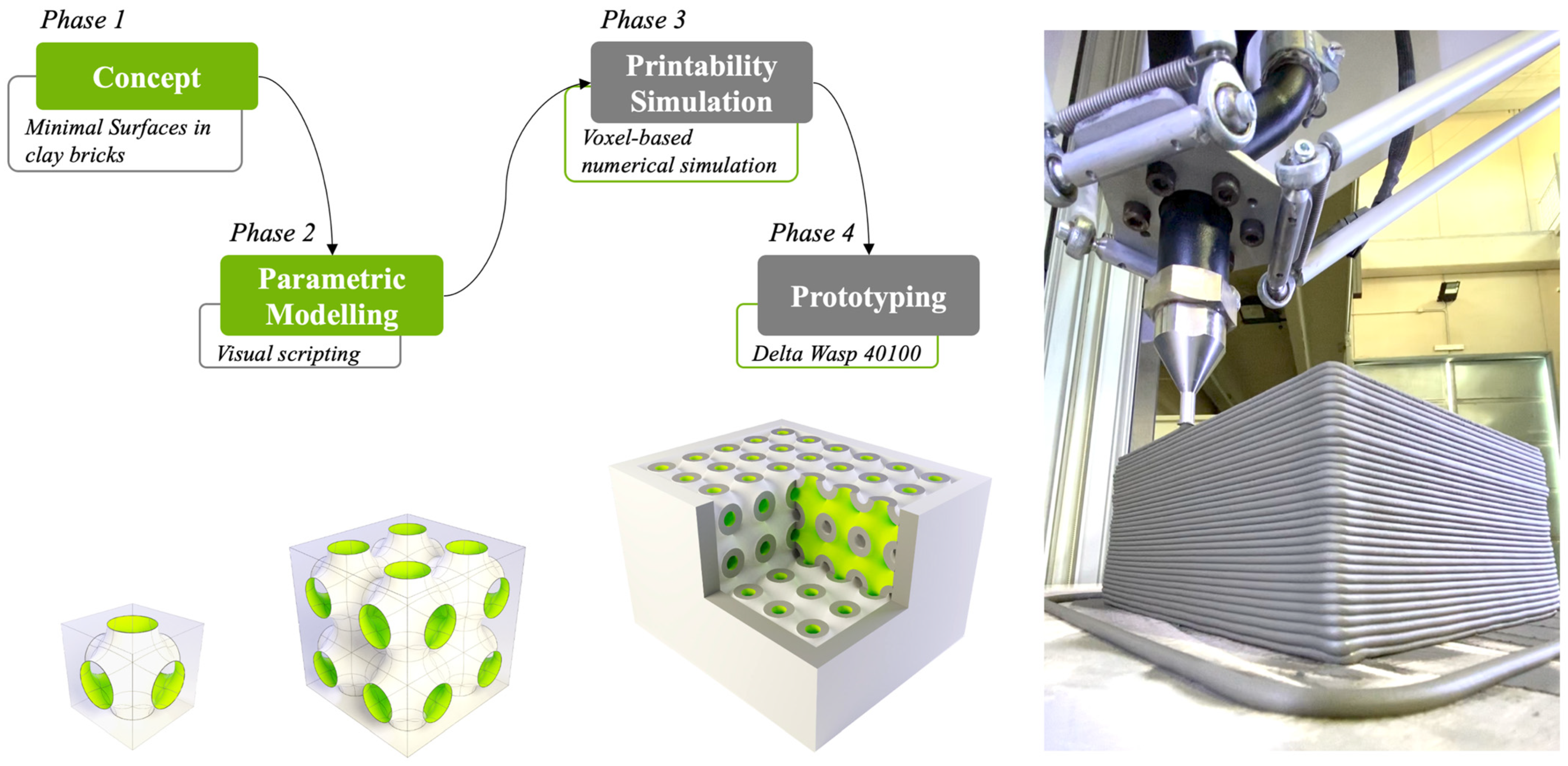
The proposed research is developed in four phases: (i) conception and design; (ii) parametric modeling; (iii) simulation and printability; (iv) prototyping. Figure 1 shows a flowchart of the four phases of the methodology (in the top left part) and the novel conceptual design and prototyping of the 3D-printed clay brick (in the bottom).
In particular, (i) in the first phase, the concept design investigates how to include minimal surfaces in the design of a clay brick realized with 3D printing.
(ii) Successively, the parametric models of the new clay bricks of are generated by exploiting algorithms-aided design [22].
(iii) In the third phase, an advanced printing simulation is developed in order to identify the best minimal surfaces configuration and other geometrical parameters suitable for designing and printing the new bricks. The simulations are obtained by linking the bricks parametric model with the Abaqus simulation software [23].
(iv) In the final phase, the best printable bricks configurations are selected for effective prototyping.
2.1. Novel Conception and Design
The conception of the new printable bricks starts from two ideas:
- (a)
- The observation of the traditional and widespread brick external shapes and related regulatory in order to respect the external dimension and the internal wall thickness (rectangle parallelepiped);
- (b)
- The use of minimal surfaces to generate the internal configuration of the bricks.
Typically for structural bricks, the length, width, and height can be consistently varied within the range 15–50 cm, 12–30 cm, and 15–25 cm respectively. The thickness of the internal walls is considered to be at a minimum 0.8 cm. In addition, the minimum thickness of the external walls (external shell) is 1 cm with a tolerance of the 10% to consider the typical imprecision of the production [24,25].
Starting from the above boundaries, the novel conceptual design of 3D printable bricks investigates how to use minimal surfaces to realize the internal geometry of the bricks. In particular, periodic minimal surfaces are used in this work because previous research has demonstrated the advantages of such shapes for 3D printing, including high mechanical properties, low pressure drop, and elastic-plastic damage [20,26,27].
2.2. Parametric Modeling of Minimal Surfaces and Periodic Minimal Surfaces
In the second phase of the methodology, the parametric models of the new printable bricks are modeled with the Grasshopper visual programming language (a visual scripting and environment that runs within the Rhinoceros 3D computer-aided design). The parametric modeling of the brick is achieved in three steps: (i) Generation of the external shell, (ii) generation of the periodic minimal surfaces, (iii) internal shape and finalization of the brick.
In the following, every step is described in detail by mentioning the specific components (in italics) to be dragged onto the Grasshopper canvas.
(i) The generation of the external shell starts from the definition of a rectangle parallelepiped by using the components rectangle, extrusion, and cap holes (by respecting the length, width, and height constraint defined in Section 2.1). By employing the component centre box and solid difference, the thickness of the external wall is completed. More in detail, these last two components operate a Boolean difference between the first parallelepiped and another one with the centre in common, i.e., the same height but reduced width and length on the basis of the desired thickness.
(ii) In parallel, periodic minimal surfaces are generated through the visual script from their implicit mathematical equations [28,29]. The functions are plotted with a domain of negative and positive exploiting the following grasshopper components: construct domain, range, cross reference, evaluate, and iso surface of the plugin “millipede” (https://wewanttolearn.wordpress.com/tag/millipede/ (accessed on 15 February 2021)).
(iii) Once the single periodic minimal surface (single geometry) is generated, it is possible to create a box array including the obtained geometry to create the internal shape of the bricks. The vertices in contact of every geometry are joined with the component join meshes and weld of the “weavebird” plugin [30] and the thickness (respecting constraint defined in Section 2.1) can be created with the components offset mesh of the “pufferfish” plugin.
Once the number of internal cells is defined and geometries have been adequately scaled (in order to perfectly fit the external shape) with the additional components (division and domain box connected to the box array), the internal geometry can be joined and finalized by using the component mesh join. To the sake of brevity, Figure 2 shows the visual script to generate the external shape of the brick, while Supplementary Figure S1 shows the whole script.
The complete parametric model (Supplementary Figure S1) can quickly change parameters of the brick—such as dimensions, external shape thickness, and internal geometry (changing the mathematical equations and consequently the minimal surface). In particular, for what concerns the internal geometry, the number of repetitions of the minimum surfaces inside the bricks can be modified in the parametrical model by considering the number of cells of the box array components.
2.3. Simulations and Printability
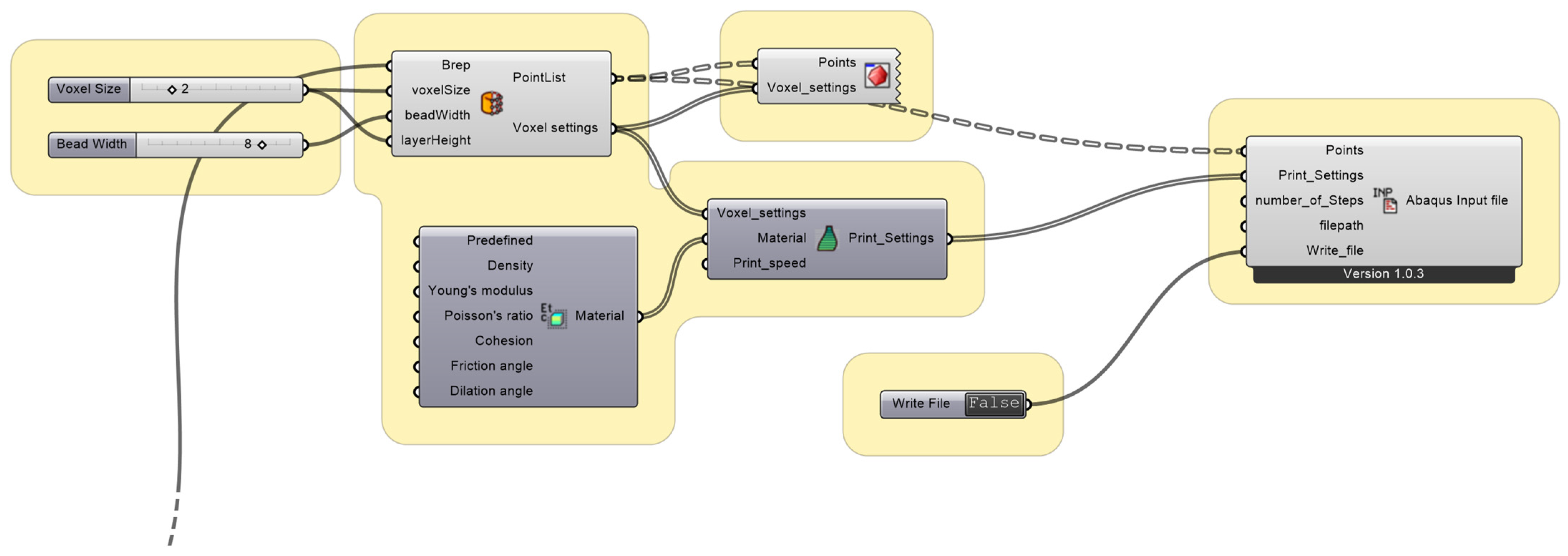
The third phase of the methodology is devoted to performing a finite element modeling (FEM) analysis of the printability of the internal cells of the bricks. Such analyses are aimed to identify the most effective minimum surfaces and the number of repetitions of the geometry within the brick. The approach is based on an effective plug-in named VoxelPrint for Grasshopper [23] that can be used to construct simulation files, designed specifically for 3D printing applications for viscous material, such as concrete. Such plugin exploits voxelization of the designed three-dimensional shapes into a set of identical finite elements and it produces ready-to-use input files for simulation in Abaqus. The approach has been initially developed for concrete printing. On the other hand, in this work, the material parameters (that can be included in the tool) are modified and adapted to simulate clay extrusion instead of concrete. The visual scripting is reported in Figure 3 and the used components are listed in the following: BerpToVoxel, Material, PrintSetting, VoxelPreview, and VoxelToAbaqus.
Note that in order to use VoxelPrint an additional part of the graphical script is needed to convert the brick geometry in an input file in the form of a B-rep (a solid represented as a collection of connected surface elements, which define the boundary between interior and exterior points) [31]. Supplementary Figure S1 shows the whole script.
Once imported in Abaqus, the file (generated as the output of the VoxelPrint plugin) already contains all the configurations to run a non-linear static analysis, useful to evaluate large displacements on the basis of the considered printing material. Another important parameter to be set is the “number_of_Steps” used for the definition of the number of progressive steps of the analysis. Every step represents a portion of the 3D printing process into which the simulation is divided to evaluate the displacements. In this way, the software is able to rebuild and simulate the whole printing process.
2.4. Prototyping
The prototyping phase has two purposes: (i) validate the results and the printability information achieved from the simulations; (ii) investigates some additional errors related to the limits of the technology in order to create useful guidelines for researchers and practitioners on how to avoid such specific printing errors.
3. Results
The proposed methodology is applied to investigate the limits of the novel design of 3D-printed bricks including different internal possible configuration inside a defined external shell. This section presents the results in three subsections according to the proposed methodology.
Firstly, a set of 18 bricks are modeled by exploiting the novel conceptual design (respecting the traditional and widespread brick external shapes) and the parametric modeling by varying the minimal surfaces and the number of internal cells of the brick.
Secondly, the results of the FEM analysis performed by ABAQUS software are presented and the best printable configurations are selected (among the 18 bricks modeled).
Thirdly, the results of the wide prototyping campaign are showed, and the validation of the simulations is discussed. The prototyping involves a total of 18 printings.
3.1. Novel Conceptual Design Results
The generation of the 3D models of the bricks precisely follows the proposed three steps of the parametric modeling (Section 2.2): (i) generation of the external shell; (ii) generation of the periodic minimal surfaces; (iii) internal shape and finalization of the brick.
In the first step, the parametric modeling starts from the definition of the external shell of the brick respecting the traditional external shapes (rectangular parallelepiped). The current research investigates small brick of 15 × 12.5 × 9 cm since this dimension can be effectively doubled or tripled to achieve standard brick and block sizes in construction (e.g., walls of 30 or 45 cm of width).
In the second step, the minimal surfaces can be generated to create the internal geometry of the brick with walls thickness of about 0.8 cm. In particular, six minimal surfaces are investigated by considering some of the most used surfaces in digital manufacturing [32,33,34]: Gyroid [28], Shwarz Primitive [28], Shoen’s Batwing [35], Battista-Costa [36,37], Diamond [29], Sherk tower [38].
In the third step, by exploiting the last part of the visual scripting, it is possible to combine multiple cells through the box array, assign thickness and automatically scale the internal geometry to perfectly join the external shell.
Figure 4 shows the single cell of minimal surfaces and the combination of many cells in a box array 2 × 2. More in detail, in the upper part, the figure displays the single cell of the minimal surface generated by using the proposed visual scripting. In the bottom part of the image, an example of the combination of multiple cells is showed (in this simplified illustration, a 2 × 2 box array is considered).
Once the parametric model is completed with the necessary information, it is possible to quickly change the internal configuration of the brick by using different minimal surfaces and box arrays setting.
As previously mentioned, in this work, 18 printable bricks models are generated by considering all the combinations of six different minimal surfaces and three different setting of box arrays including the configurations 2.5 × 3, 4 × 5, and 5 × 5.
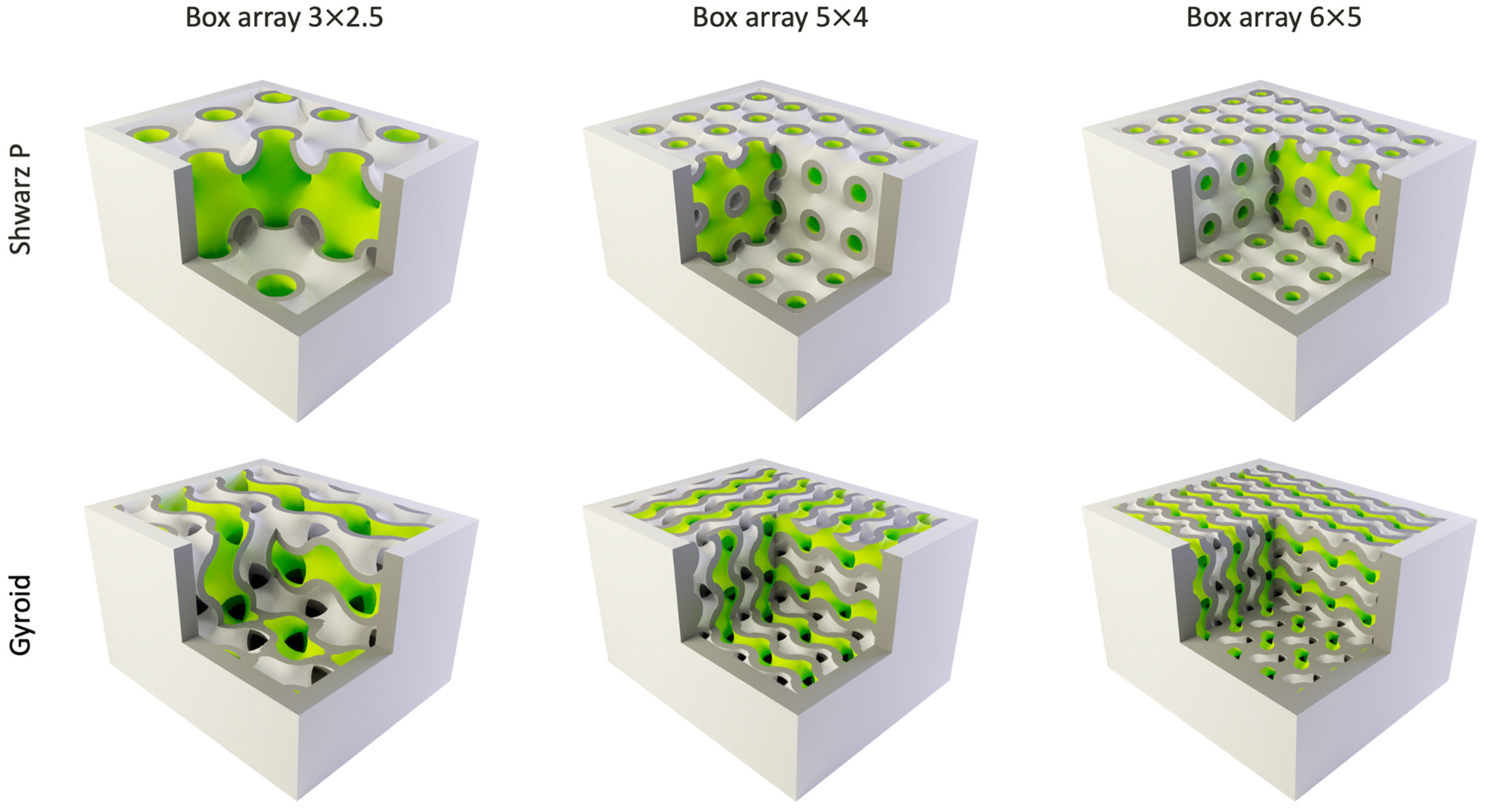
Figure 5 shows an example of how different configurations of the 3D bricks models can be investigated by varying minimal surfaces and box arrays.
3.2. Simulation Results
With the aim of achieving a complete understanding of the internal brick’s geometry printability, a series of FEM analyses of bonding is undertaken by using SIMULIA ABAQUS software. In particular, the printability of the cells is investigated by considering the minimum surface typology and the number of repetitions of the geometry. Consequently, in the ABAQUS software, 18 simulations are considered including three different dimensions for every one of the six different minimum surfaces. Such analysis allows to perfectly simulate the 3D printing setting including both the layer dimension, the thickness of the extrusion, printing speed and the characteristic of the material.
In particular, the following characteristics are set in the simulation according to the selected 3D printer and material defined for the prototyping. Note that the used setting is defined considering the current common features of printers on the market, e.g., Delta Wasp 40100 for clay. Both material and printing characteristics are defined in VoxelPrint and reported automatically in Abaqus by the imported model file. The material simulation parameters are specified in Figure 3, according to the supplier specifications and the related literature [39]. The simulation is also performed consistently with the real machine printing process: a layer thickness of 1 mm printed by a nozzle of 2 mm diameter and a printing speed of 30 mm/s.
In addition, some boundary conditions are set in order to consider a simulation consistent with the whole geometry while analyzing an isolated cell of the different minimal surfaces. For the continuity of the geometries, in each simulated cell, the orthogonal displacements of the cell cutting plane are not allowed.
The outcome of the simulation for every cell can be interpreted with three possible outputs: cell collapse, partial cell collapse, and perfectly printable model.
In particular, the cell collapse refers to an irreversible collapse that generates a necessary stop of the 3D printing (the collapse is so severe that it does not lead to the positioning of another layer of material).
The partial cell collapse means that a part of the model suffers a slight collapse during the extrusion, but 3D printing can theoretically continue. In addition, such criticality affects the final printed geometry that cannot be exactly the same of the designed 3D model.
In the perfectly printable model, there are no collapses and no significant local deformations.
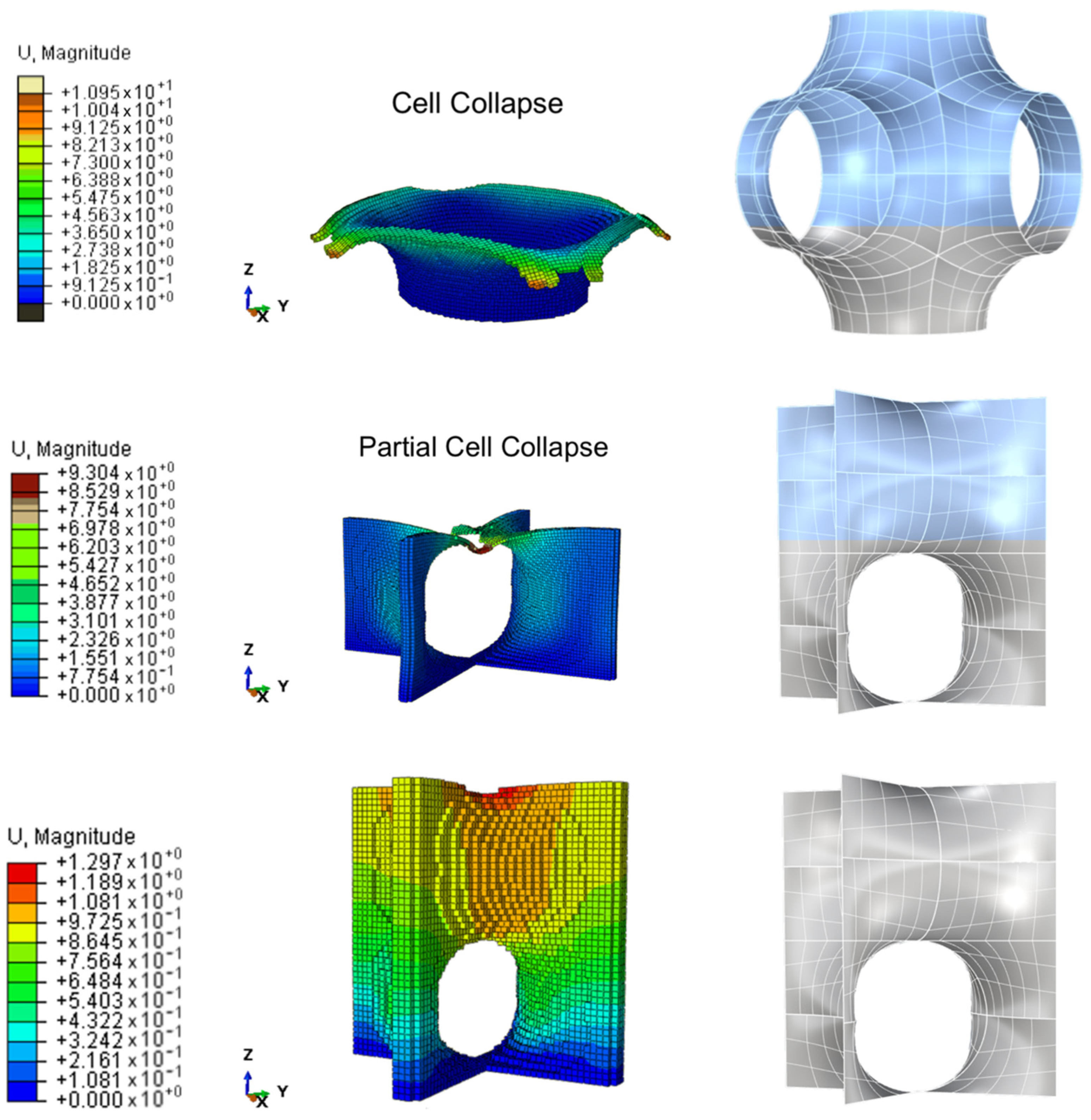
Figure 6 shows three examples of the FEM results, one for every possible output.
More in detail, the upper part the Figure 6 shows the cell collapse corresponding to the Shwarz P minimal surface in the configuration of a 2.5 × 3 box array. The central part of the figure shows the partial collapse of a Sherk tower minimal surface in the configuration of a 2.5 × 3 box array. The bottom part of the figure shows the effective printable model of a Sherk tower minimal surface in the configuration of a 4 × 5 box array.
In Figure 6, the nodal displacements are highlighted in a chromatic magnitude scale. In the cell collapse, high deformations (~7 mm) are diffused along the last layer where the collapse occurs with highest values in the most overhanging portions (~11 mm).
Also in the partial cell collapse, high values of deformations (~9 mm) are detected. On the contrary, in this case, the large displacements are focused in a very small portion of the central part of the cell, while the rest of the geometry remains with very low deformations (~0.07 mm).
The perfectly printable simulation is confirmed by the deformation values of the last layers (less than 1 mm) about one order of magnitude smaller than the cases of cell collapse and partial collapse.
In total, the analysis shows that 12 of the cells of the designed 18 bricks could be effectively printed and one of suffers a partial internal collapse.
Table 1 summarizes the printability results of the internal geometries of the 18 designed blocks obtained with the FEM analysis.
3.3. 3D Printing Prototypes
The last phase consists of the realization of the prototypes of the 18 designed bricks. The prototyping phase is designed to verify that the FEM analysis effectively simulate the 3D printing of the bricks and to investigate other unpredictable printing errors. For this purpose, the 18 bricks including six different minimal surfaces and three different array configurations (box arrays 2.5 × 3, 4 × 5 and 5 × 5) are printed in the FabLab Poliba laboratory of the Politecnico di Bari (Bari, Italy). In particular, the prototyping exploits the slicing software Simplify3D and the 3D printer Delta Wasp 40100 for clay. The raw material used for the printing is clay, a type of fine-grained natural soil material. Table 2 shows the specific mix compositions of the used clay while the percentage of water is 20%. In addition, the printing laboratory is a climate-controlled room with constant indoor microclimate. The temperature is around 20 °C and the relative humidity is about 60%.
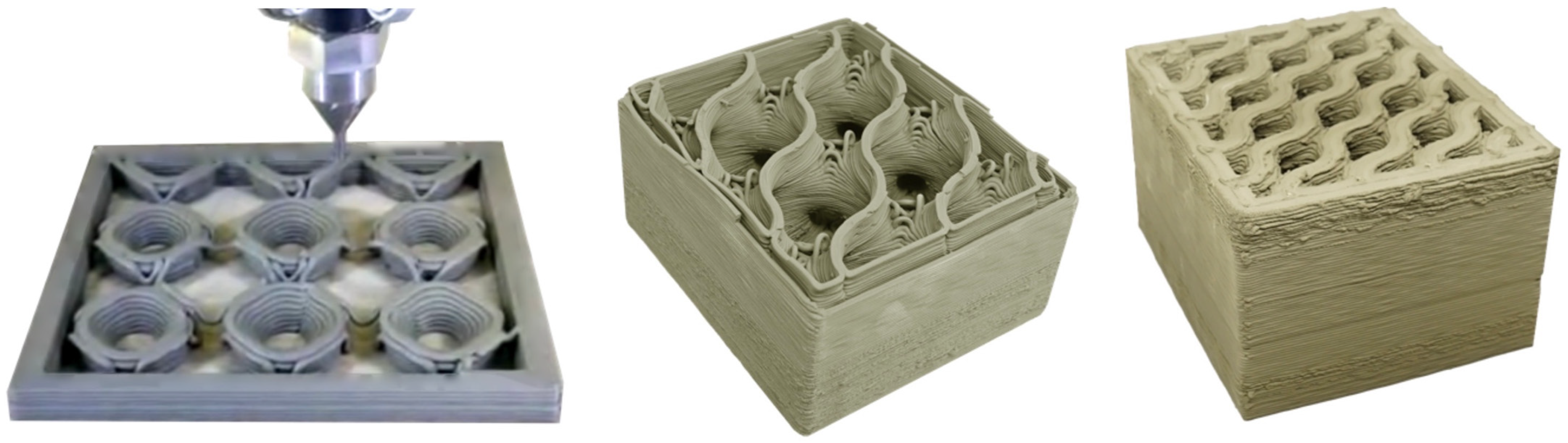
The printing setting includes a layer thickness of 1 mm a nozzle size of 2 mm diameter and printing speed about 30 mm/s (analogously to the print configuration of the FEM analysis). The results of the prototyping phase are perfectly consistent with the outputs of the FEM analyses. To provide some examples, Figure 7 shows the collapse, partial cell collapse, and the brick perfectly printable in the configuration of Shwarz P 2.5 × 3, Sherk tower 2.5 × 3, and Sherk tower 4 × 5 respectively (the same example of Figure 6).
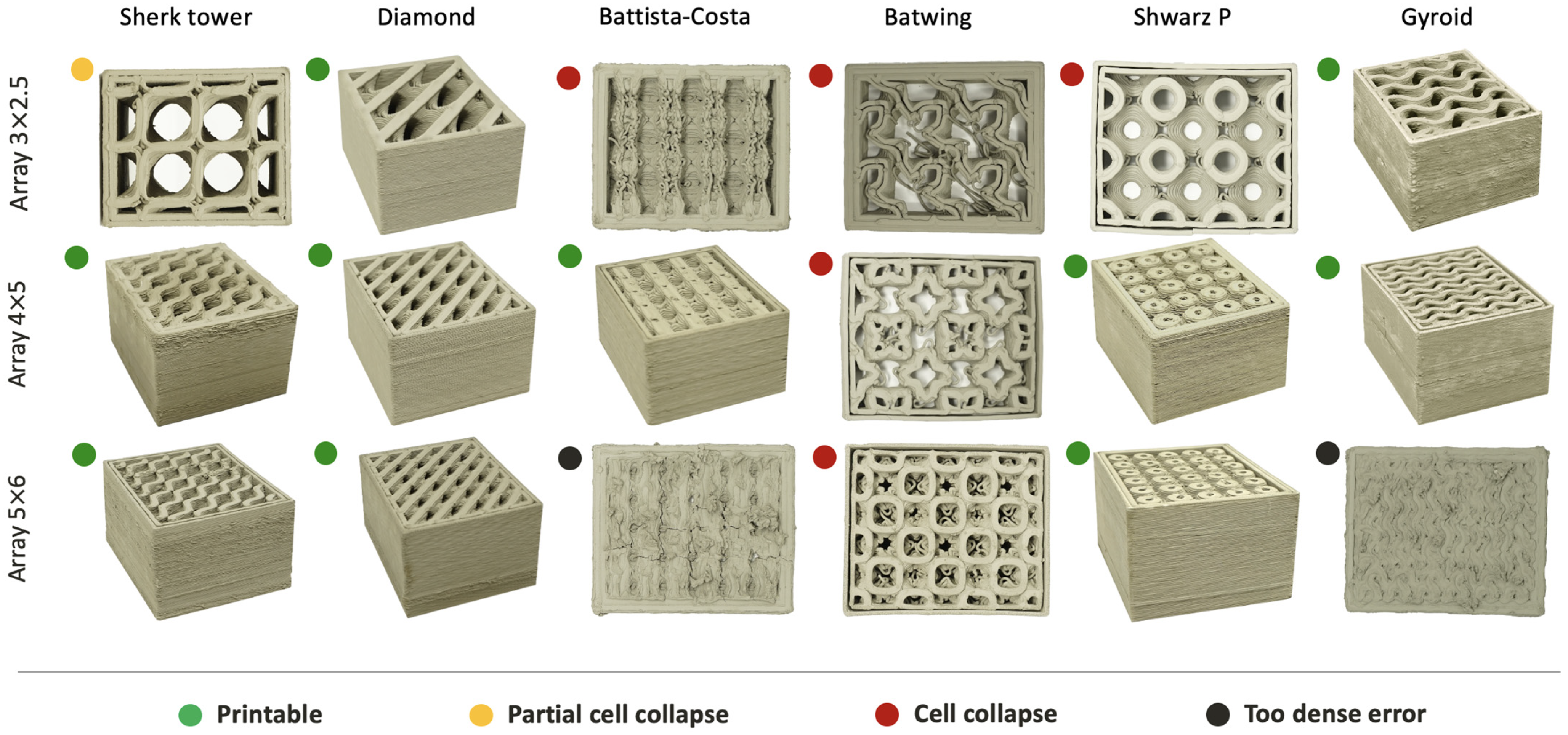
More in detail, the geometries that collapse according to the FEM model effectively collapse even in prototyping (in these cases the printing must be stopped). Even the partial collapse of the Sherk tower 2.5 × 3 occurs as predicted by the FEM simulation. The other bricks can be easily printed as foreseen by the FEM analysis with the only difference for the Batista-costa and Gyroyd geometry in the configuration array 5 × 6. Indeed, these geometries have a complex texture and a very dense geometry (e.g., Gyroid has a very complex shape and a void ratio of less than 20%) which causes critical printing issues. In particular, the resolution of the 3D printer is not enough to create the small voids and the extruded geometry loses its characteristic geometric features (extruded material starts to overlap even when it should not). This last printing error is named hereafter ‘too dense error’.
Figure 8 shows the 18 3D-printed bricks (with different internal geometries) and the printing result in terms of too dense error, collapse, partial cell collapse, perfectly printable.
4. Discussion and Guidelines
In recent years, few applications can be found in literature concerning the field of 3D-printed clay bricks. On the other hand, some research institutes and companies (IAAC and Wasp) are demonstrating the huge potential of clay 3D printing for sustainable construction [8,9,40,41].
To this aim, this section discusses the characteristics and the differences of the proposed bricks by comparing the proposed ideas and results with previous investigations [5].
The most relevant research in the 3D printing of large walls and large blocks is performed by Izard et al. [8] in the IAAC institute where cable-driven parallel robots were applied. More in detail, the IAAC researchers investigated different aspects of 3D-printed clay building components—including columns [40], bricks, and large blocks with various types of openings [41]. The IAAC research demonstrated the potential of such technology and stated the current limits of the application at the large scale. In addition, such investigation did not delve into complex internal geometries and printability limits since the focus was directed towards the potential of large-scale applications.
On the contrary, the current proposal investigates small bricks which can be made with commercial printers, such as the Delta Wasp 40100, for clay. In the field of small 3D-printed bricks, the first research investigation has been conducted by Cruz et al. [12,13,14] in the School of Architecture of the University of Minho (Guimarães, Portugal). This Portuguese research contains the results of more than 3 years of research and provides the evidence of the performance potential of the 3D-printed bricks, including the freedom to create customized shapes.
Other investigations confirmed the potential of both geometry and mass customization in 3D-printed clay bricks for different applications [42,43] (artistic and architectural) and multi objective performances [15,44] (e.g., structural and thermal). On the other hand, none of these previous studies investigate the possibility and limitations of printing complex geometries inside bricks [5].
In the current work, firstly a suitable methodology is defined in order to design, simulate (the 3D printing), and prototype novel complex clay bricks. Secondly, geometries with well-known remarkable mechanical properties such as minimal surfaces and periodic minimal surfaces are used to generate a parametric modeling with the novel complex internal shapes of the bricks.
Six different minimal surfaces are investigated in three different internal configurations (with a total of 18 bricks) in order to identify the most printable configurations.
In conclusion, the most promising geometry is the Diamond, printable in all the investigated configurations. Moreover, a good printability is also found in the Sherk Tower, Swarts P, and Gyroyd since these geometries can be effectively printed in different internal configurations of the bricks. Batwing is the most complex geometry and not suggested to be effectively printed in a clay brick with the current technologies.
4.1. Guideline for the Design of the Novel Bricks (Avoid Printing Error)
Three different 3D printing errors have been identified in the attempt to print bricks with complex internal geometries: cell collapse, partial cell collapse, and the too dense error.
The cell collapse configurations occur when internal geometry is increased too much in size, the cells become large and consequently are difficult to print due to the presence of larger surfaces with horizontal tangents. The research points out that geometries such as Diamond, Gyroid, and Sherk tower are less prone to this problem due to their geometry.
The partial cell collapse occurs exactly for the same reason of the cell collapse. On the contrary, in this case, the cell suffers a deformation only and the printing can be continued even if the result could be different form the designed 3D model. In this case, the limit of the cell size has been reached. If the cell dimension is further enlarged, a collapse would occur. Both partial cell collapse and collapse can be predicted and avoided with the proposed FEM analysis.
The too dense error differs from the two previous ones because it cannot be predicted in the FEM analysis. In addition, this error occurs when the geometry is too dense (the number of arrays is too high and the void ratio decreases reaching the limit of the printing). In this case, the tolerance and precision of the machine are not sufficient to actually generate the shape. The extruded material starts to overlap where it should not, and the result is a fully deformed shape that is different from the original 3D model. This specific error depends from the printed material and the precision of the 3D printer. Consequently, it may or may not occur depending on the used technology.
4.2. Limits of the Technology and Future Direction
The presented research, and in particular the prototyping of the complex bricks, pointed out three technological limits which need to be faced in the future in order to ensure a sustainable and wide application of clay 3D printing in the construction sector.
The principal drawback found in the experimental phase concerns the printing time of the bricks. Indeed, the average printing time is about 3 h. The complete overview of the printing time of the proposed bricks is showed in Table 3. Consequently, the production of bricks to realize a wall 3 × 4 m may require more than 400 printing hours.
The second limit concerns the printing of some of the geometries that collapse without a support [45]. In addition, recent studies have demonstrated how spatial 3D-printed polymer elements can be used to efficiently reinforce 3D-printed geometries [46]. Such intuition of Katzer and Szatkiewicz could be combined with the complex geometries investigated in the current work to optimize efficiency of clay bricks.
The third important limits of current clay 3D printing concern the control of the extrusion of the material. The extrusion of the clay 3D printer is affected by small variations in density of the clay and the mechanics of the printer extruder. These limits lead to insufficient precision in printing very dense geometries with a low void’s ratio (too dense error). In this field, it would be useful to improve the existing technology with an automatic extrusion flow control in order to increase the precision and avoid inaccuracies of the printing.
In addition, in the proposed research, the printing phase is not significantly affected by the indoor micro-climate since the height of the bricks is very small. On the contrary, in larger printings [40,41] temperature and humidity can reduce or speed up the hardening of the material. To this aim, a future development of the technology can improve the control on the printing material. An automatic control could correct the extrusion flow and the percentage of water in the material preparation tank. Consequently, the extruded material features can be adjusted in real time on the basis of external temperature and humidity to optimize the printing.
In conclusion, it would be useful to increase the automation of processes, for example by exploiting the production with 3D printing together with collaborative robots [47] to reduce manpower and the consequent production times.
5. Conclusions
This paper explores, for the first time, the possibility of realizing new 3D-printed clay bricks for building construction with complex internal geometries based on minimal surfaces. A novel methodological approach is proposed to design, test, and prototype these new sustainable bricks including three main steps.
Firstly, the conception and design are established for respecting external dimensions and internal wall thickness of classical structural bricks.
Secondly, a parametric modeling is developed to realize 3D-printed bricks and to generate the input files for a FEM simulation in Abaqus suitable for verifying the printability.
Thirdly, a wide prototyping campaign is performed to realize the prototypes of 3D-printed clay bricks and validate the performed analysis.
In total, a set of 18 brick models are designed, the relative printing is simulated with a FEM analysis and the effective 3D printings are realized. In conclusion, the most promising configuration is based on the minimal surface of Diamond, followed in the second place by Sherk tower, Swarts P, and Gyroyd.
In comparison with previous research, the proposed work demonstrates the potential of 3D printing in achieving 3D-printed bricks by exploiting different internal configurations based on the minimal surfaces. In addition, the current research proposes a methodology for designing and printing by using modern FEM analysis to simulate the printability. On the contrary, previous experiences are mainly focused on the investigation of bricks for architectural use only and without the complex internal geometry. Consequently, in the previous works the simplified geometry did not require the FEM analyses proposed in the current work to simulate the printability.
This research opens up new sustainable perspectives and possibilities to use 3D printing for the realization of high-performance 3D-printed brick walls by reducing the consumption of raw materials and optimizing the internal shape of the brick. On the other hand, the research emphasizes the need for an improvement of the technology to be competitive with traditional techniques from a realization time point of view.
Future research will investigate both the structural and thermal performances of the achieved printable bricks configurations in order to identify most effective ones to realize high-performance 3D-printed brick walls. Beyond this, another study will investigate the possibility of modifying the external shell of the brick in order to enhance the combination of brick 3D printing and the automatic construction of walls with collaborative robotic arms.
Supplementary Materials
The following supporting information can be downloaded at: https://www.mdpi.com/article/10.3390/su14020598/s1, Supplementary Figure S1: The complete visual scripting to generate the bricks.
Author Contributions
Conceptualization, V.S.; Data curation, V.S. and F.F.; Formal analysis, V.S. and F.P.; Funding acquisition, N.P.; Investigation, V.S.; Methodology, V.S.; Resources, V.S.; Software, V.S., F.P. and F.F.; Supervision, V.S. and N.P.; Validation, V.S. and F.P.; Visualization, V.S. and F.F.; Writing—original draft, V.S.; Writing—review and editing, V.S. and N.P. All authors have read and agreed to the published version of the manuscript.
Funding
This research and APC was funded by “Fondi Casa delle Tecnologie Emergenti Matera”.
Institutional Review Board Statement
Not applicable.
Informed Consent Statement
Not applicable.
Data Availability Statement
Not applicable.
Acknowledgments
A special thanks is addressed to FabLab Bitonto for supporting the development of the prototype in the laboratory “Fablab Poliba”.
Conflicts of Interest
The authors declare no conflict of interest.
References
- Volpe, S.; Petrella, A.; Sangiorgio, V.; Notarnicola, M.; Fiorito, F. Preparation and characterization of novel environmentally sustainable mortars based on magnesium potassium phosphate cement for additive manufacturing. AIMS Mater. Sci. 2021, 8, 640–658. [Google Scholar] [CrossRef]
- Parisi, F.; Mangini, A.M.; Fanti, M.P.; Parisi, N. A Drone-Assisted 3D Printing by Crane Structures in Construction Industry. In Proceedings of the 2021 IEEE 17th International Conference on Automation Science and Engineering (CASE), Lyon, France, 23–27 August 2021; pp. 171–176. [Google Scholar]
- Hansmeyer, M.; Dillenburger, B. Digital grotesque: Towards a micro-tectonic architecture. SAJ Serb. Archit. J. 2013, 5, 194–201. [Google Scholar] [CrossRef]
- Volpe, S.; Sangiorgio, V.; Petrella, A.; Coppola, A.; Notarnicola, M.; Fiorito, F. Building Envelope Prefabricated with 3D Printing Technology. Sustainability 2021, 13, 8923. [Google Scholar] [CrossRef]
- Wolf, A.; Rosendahl, P.L.; Knaack, U. Additive manufacturing of clay and ceramic building components. Autom. Constr. 2022, 133, 103956. [Google Scholar] [CrossRef]
- Salet, T.A.; Ahmed, Z.Y.; Bos, F.P.; Laagland, H.L. Design of a 3D printed concrete bridge by testing. Virtual Phys. Prototyp. 2018, 13, 222–236. [Google Scholar] [CrossRef] [Green Version]
- Parisi, N. 3D printing for earthen architecture. In Proceedings of the 7th International Conference on Architecture and Built Environment with AWARDs, S.ARCH 2020, Tokyo, Japan, 7–9 April 2020; pp. 282–291, ISBN 9783982075853. [Google Scholar]
- Izard, J.B.; Dubor, A.; Hervé, P.E.; Cabay, E.; Culla, D.; Rodriguez, M.; Barrado, M. Large-scale 3D printing with cable-driven parallel robots. Constr. Robot. 2017, 1, 69–76. [Google Scholar] [CrossRef]
- Figliola, A.; Battisti, A. Post-Industrial Robotics: Exploring Informed Architecture; Springer Nature: Basingstoke, UK, 2021. [Google Scholar]
- Cruz, P.J.; Figueiredo, B.; Carvalho, J.; Campos, T. Additive Manufacturing of Ceramic Components for Façade Construction. J. Facade Des. Eng. 2020, 8, 1–20. [Google Scholar]
- Suon, P. Dynamic Ceramic. Ph.D. Dissertation, University of California, Berkeley, CA, USA, 2016. [Google Scholar]
- Carvalho, J. Free-Form Ceramic Vault System-Taking Ceramic Additive Manufacturing to Real Scale. Matter Additive Manufacturing. 2019, Volume 1, p. 485. Available online: http://papers.cumincad.org/cgi-bin/works/Show?ecaadesigradi2019_592 (accessed on 10 November 2021).
- Carvalho, J.; Cruz, P.J.; Figueiredo, B. 3D printed ceramic vault shading systems. In Proceedings of the IASS Annual Symposia, Boston, MA, USA, 16–20 July 2018; Volume 2018, pp. 1–8. [Google Scholar]
- Cruz, P.J.; Camões, A.; Figueiredo, B.; Ribeiro, M.J.; Renault, J. Additive manufacturing effect on the mechanical behaviour of architectural stoneware bricks. Constr. Build. Mater. 2020, 238, 117690. [Google Scholar] [CrossRef]
- Peters, B.; Sharag-Eldin, A.; Callaghan, B. Development of a simple Hot Box to determine the thermal characteristics of a three-dimensional printed bricks. In Proceedings of the ARCC 2017 Conference—Architecture of Complexity, Salt Lake City, UT, USA, 14–17 June 2017; pp. 14–17. [Google Scholar]
- Cruz, P.J.; Knaack, U.; Figueiredo, B.; Witte, D.D. Ceramic 3D printing–The future of brick architecture. In Proceedings of the IASS Annual Symposia, Hamburg, Germany, 25–28 September 2017; Volume 2017, pp. 1–10. [Google Scholar]
- Barbosa, I.V.; Figueiredo, B. Optimized brick—Print optimization. In Challenges for Technology Innovation: An Agenda for the Future; CRC Press: Boca Raton, FL, USA, 2017; pp. 207–210. [Google Scholar]
- Wohlgemuth, M.; Yufa, N.; Hoffman, J.; Thomas, E.L. Triply periodic bicontinuous cubic microdomain morphologies by symmetries. Macromolecules 2001, 34, 6083–6089. [Google Scholar] [CrossRef]
- Séquin, C.H. Volution’s Evolution; Association for Computing Machinery: New York, NY, USA, 2004; p. 79. [Google Scholar]
- Fan, X.; Tang, Q.; Feng, Q.; Ma, S.; Song, J.; Jin, M.; Fuyu, G.; Jin, P. Design, mechanical properties and energy absorption capability of graded-thickness triply periodic minimal surface structures fabricated by selective laser melting. Int. J. Mech. Sci. 2021, 204, 106586. [Google Scholar] [CrossRef]
- Almeida, H.A.; da Silva Bártolo, P.J. Mathematical Modeling of 3D Tissue Engineering Constructs. 3D Printing and Biofabrication; Springer: Berlin, Germany, 2017; pp. 1–30. [Google Scholar]
- Tedeschi, A.; Lombardi, D. The Algorithms-Aided Design (AAD). In Informed Architecture; Springer: Cham, Switzerland, 2018; pp. 33–38. [Google Scholar]
- Vantyghem, G.; Ooms, T.; De Corte, W. VoxelPrint: A Grasshopper plug-in for voxel-based numerical simulation of concrete printing. Autom. Constr. 2021, 122, 103469. [Google Scholar] [CrossRef]
- Agostini, L.; Labanti, M. European Standard Related To Clay Masonry Units. Ind. Laterizi 2000, 11, 114–125. [Google Scholar]
- UNI Ente Nazionale Italiano di Unificazione. 771-1: 2005. Specification for Masonry Units-Part, 1. Available online: https://standards.iteh.ai/catalog/standards/cen/0597684f-a18a-48cb-a538-6a9ab3762721/en-771-1-2003-a1-2005 (accessed on 1 January 2022).
- Al-Ketan, O.; Pelanconi, M.; Ortona, A.; Abu Al-Rub, R.K. Additive manufacturing of architected catalytic ceramic substrates based on triply periodic minimal surfaces. J. Am. Ceram. Soc. 2019, 102, 6176–6193. [Google Scholar] [CrossRef]
- Restrepo, S.; Ocampo, S.; Ramírez, J.A.; Paucar, C.; García, C. Mechanical properties of ceramic structures based on Triply Periodic Minimal Surface (TPMS) processed by 3D printing. J. Phys. Conf. Ser. 2017, 935, 012036. [Google Scholar] [CrossRef] [Green Version]
- Balabanov, S.V.; Makogon, A.I.; Sychov, M.M.; Gravit, M.V.; Kurakin, M.K. Mechanical properties of 3D printed cellular structures with topology of triply periodic minimal surfaces. Mater. Today 2020, 30, 439–442. [Google Scholar] [CrossRef]
- Buratti, G. Algorithmic modelling of triply periodic minimal surface. In Computational Morphologies; Springer: Cham, Switzerland, 2018; pp. 55–62. [Google Scholar]
- Piacentino, G. Weaverbird: Topological mesh editing for architects. Archit. Des. 2013, 83, 140–141. [Google Scholar] [CrossRef]
- Goldbach, A.K.; Bauer, A.M.; Wüchner, R.; Bletzinger, K.U. CAD-integrated parametric lightweight design with Isogeometric B-Rep Analysis. Front. Built Environ. 2020, 6, 44. [Google Scholar] [CrossRef]
- Sathishkumar, N.; Vivekanandan, N.; Balamurugan, L.; Arunkumar, N.; Ahamed, I. Mechanical Properties of Triply Periodic Minimal Surface based lattices made by Polyjet Printing. Mater. Today 2020, 22, 2934–2940. [Google Scholar] [CrossRef]
- Bobbert, F.S.L.; Lietaert, K.; Eftekhari, A.A.; Pouran, B.; Ahmadi, S.M.; Weinans, H.; Zadpoor, A.A. Additively manufactured metallic porous biomaterials based on minimal surfaces: A unique combination of topological, mechanical, and mass transport properties. ACTA Biomater. 2017, 53, 572–584. [Google Scholar] [CrossRef] [PubMed] [Green Version]
- Zadpoor, A.A. Additively manufactured porous metallic biomaterials. J. Mater. Chem. 2019, 7, 4088–4117. [Google Scholar] [CrossRef] [PubMed] [Green Version]
- Kapfer, S.C.; Hyde, S.T.; Mecke, K.; Arns, C.H.; Schröder-Turk, G.E. Minimal surface scaffold designs for tissue engineering. Biomaterials 2011, 32, 6875–6882. [Google Scholar] [CrossRef] [PubMed]
- Meeks III, W.; Pérez, J. The classical theory of minimal surfaces. Bull. Am. Math. Soc. 2011, 48, 325–407. [Google Scholar] [CrossRef] [Green Version]
- Batista, V.R. A family of triply periodic Costa surfaces. Pac. J. Math. 2003, 212, 347–370. [Google Scholar] [CrossRef] [Green Version]
- Hoffman, D.; Meeks, W.H. Limits of minimal surfaces and Scherk’s Fifth Surface. Arch. Ration. Mech. Anal. 1990, 111, 181–195. [Google Scholar] [CrossRef]
- Lancellotta, R. Geotechnical Engineering; Taylor and Francis, CRC Press: London, UK; New York, NY, USA, 2008. [Google Scholar]
- Pylos. 2013. Available online: http://pylos.iaac.net/main.html (accessed on 11 December 2021).
- Terraperforma. 2017. Available online: https://iaac.net/project/terraperforma (accessed on 11 December 2021).
- Lange, C.; Holohan, D. Ceramic in formation pavilion. In Proceedings of the 25th International Conference on Computer-Aided Architectural Design Research in Asia, Hong Kong, China, 15–18 April 2019; pp. 103–112. [Google Scholar]
- HEXASHADE. 2019. Available online: https://www.aclab-idegui.org/hexashade (accessed on 11 December 2021).
- Paoletti, I. Mass customization with additive manufacturing: New perspectives for multi performative building components in architecture. Procedia Eng. 2017, 180, 1150–1159. [Google Scholar] [CrossRef]
- Gurrala, P.K.; Regalla, S.P. Optimization of support material and build time in fused deposition modeling (FDM). Appl. Mech. Mater. 2012, 110, 2245–2251. [Google Scholar] [CrossRef]
- Katzer, J.; Szatkiewicz, T. Effect of 3D Printed Spatial Reinforcement on Flexural Characteristics of Conventional Mortar. Materials 2020, 13, 3133. [Google Scholar] [CrossRef]
- Bonwetsch, T. Robotic assembly processes as a driver in architectural design. Nexus Netw. J. 2012, 14, 483–494. [Google Scholar] [CrossRef] [Green Version]
Figure 1.
Flowchart of the four phases of the proposed methodology.

Figure 2.
Extract of the visual scripting to generate the external shell of the bricks.

Figure 3.
Visual scripting to create the input files for simulation in Abaqus.

Figure 4.
Single cell of minimal surfaces and combination of many cells in a box array 2 × 2.

Figure 5.
Different configurations of the 3D bricks: three different box arrays for the Shwarz P and Gyroid minimal surfaces.
Figure 5.
Different configurations of the 3D bricks: three different box arrays for the Shwarz P and Gyroid minimal surfaces.

Figure 6.
Three examples of the FEM analysis results: collapse, partial cell collapse, and perfectly printable.
Figure 6.
Three examples of the FEM analysis results: collapse, partial cell collapse, and perfectly printable.

Figure 7.
Collapse (left), partial cell collapse (central photo), and the perfectly printable brick (right).
Figure 7.
Collapse (left), partial cell collapse (central photo), and the perfectly printable brick (right).

Figure 8.
Prototyping and 3D printing of the 18 bricks and specification of the results in terms of too dense error, collapse, partial cell collapse, and perfectly printable.
Figure 8.
Prototyping and 3D printing of the 18 bricks and specification of the results in terms of too dense error, collapse, partial cell collapse, and perfectly printable.


Table 1.
Output of FEM analyses in term of printability of the 18 investigated geometries.
| Simulation Results | Printability | ||
|---|---|---|---|
| Minimal Surface | Box Array 2.5 × 3 | Box Array 4 × 5 | Box Array 5 × 6 |
| Gyroid | Printable | Printable | Printable |
| Shwarz P | Geometry collapse | Printable | Printable |
| Batwing | Geometry collapse | Geometry collapse | Geometry collapse |
| Battista-Costa | Geometry collapse | Printable | Printable |
| Diamond | Printable | Printable | Printable |
| Sherk tower | Partial collapse | Printable | Printable |
Green colour corresponds to “Printable”; Yellow colour corresponds to “Partial collapse”; Red colour corresponds to “Geometry collapse”.
Table 2.
Mix composition.
| Composition | SiO2 | Al2O3 | TiO2 | Fe2O3 | CaO | MgO | K2O | Na2O | CaCo3 |
|---|---|---|---|---|---|---|---|---|---|
| 3D printable clay | 43.8% | 15.3% | 0.5% | 4.1% | 11.6% | 1.8% | 2.6% | 1.5% | 19.3% |
SiO2 (Silica); Al2O3 (Aluminium oxide); TiO2 (Titanium dioxide); Fe2O3 (Ferric oxide); CaO (Calcium oxide); MgO (Magnesium oxide); K2O (Potassium oxide); Na2O (Sodium oxide); CaCo3 (Calcium carbonate).
Table 3.
Printing time of the 18 bricks.
| Minumal Surface | Box Array 2.5 × 3 | Box Array 4 × 5 | Box Array 5 × 6 |
|---|---|---|---|
| Gyroid | 4 h 27 min | 3 h 10 min | 4 h 27 min |
| Shwarz P | Geometry collapse | 2 h 40 min | 3 h 35 min |
| Batwing | Geometry collapse | Geometry collapse | Geometry collapse |
| Battista-Costa | Geometry collapse | 2 h 40 min | 3 h 00 min |
| Diamond | 3 h 20 min | 1 h 40 min | 3 h 20 min |
| Sherk tower | 1 h 50 min | 2 h 20 min | 2 h 50 min |
Green colour corresponds to “Printable”; Yellow colour corresponds to “Partial collapse”; Red colour corresponds to “Geometry collapse”; Black colour corresponds to “Too dense error”.
Publisher’s Note: MDPI stays neutral with regard to jurisdictional claims in published maps and institutional affiliations. |
© 2022 by the authors. Licensee MDPI, Basel, Switzerland. This article is an open access article distributed under the terms and conditions of the Creative Commons Attribution (CC BY) license (https://creativecommons.org/licenses/by/4.0/).
Share and Cite
MDPI and ACS Style
Sangiorgio, V.; Parisi, F.; Fieni, F.; Parisi, N. The New Boundaries of 3D-Printed Clay Bricks Design: Printability of Complex Internal Geometries. Sustainability 2022, 14, 598. https://doi.org/10.3390/su14020598
AMA Style
Sangiorgio V, Parisi F, Fieni F, Parisi N. The New Boundaries of 3D-Printed Clay Bricks Design: Printability of Complex Internal Geometries. Sustainability. 2022; 14(2):598. https://doi.org/10.3390/su14020598
Chicago/Turabian StyleSangiorgio, Valentino, Fabio Parisi, Francesco Fieni, and Nicola Parisi. 2022. "The New Boundaries of 3D-Printed Clay Bricks Design: Printability of Complex Internal Geometries" Sustainability 14, no. 2: 598. https://doi.org/10.3390/su14020598
Note that from the first issue of 2016, this journal uses article numbers instead of page numbers. See further details here.