Predicted Absorption Performance of Cylindrical and Rectangular Permeable Membrane Space Sound Absorbers Using the Three-Dimensional Boundary Element Method


Abstract
:1. Introduction
2. Formulation
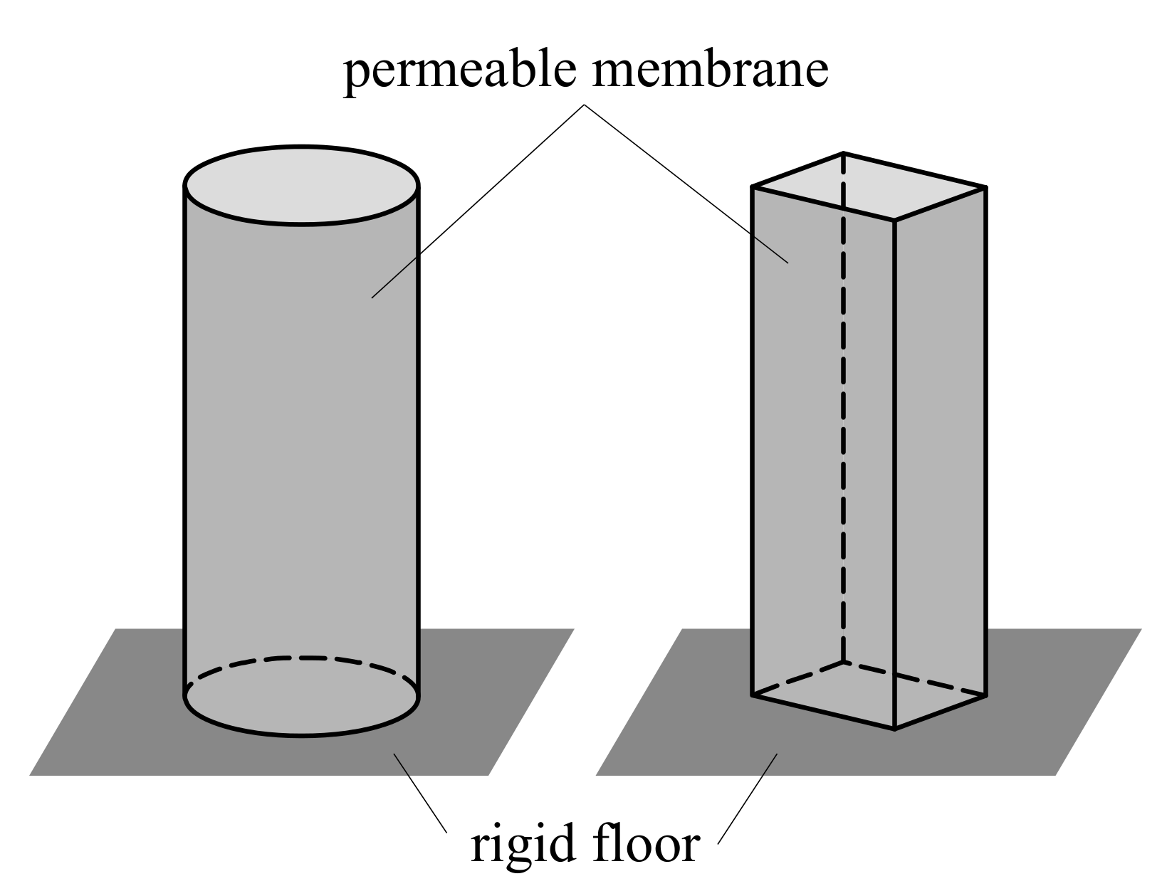
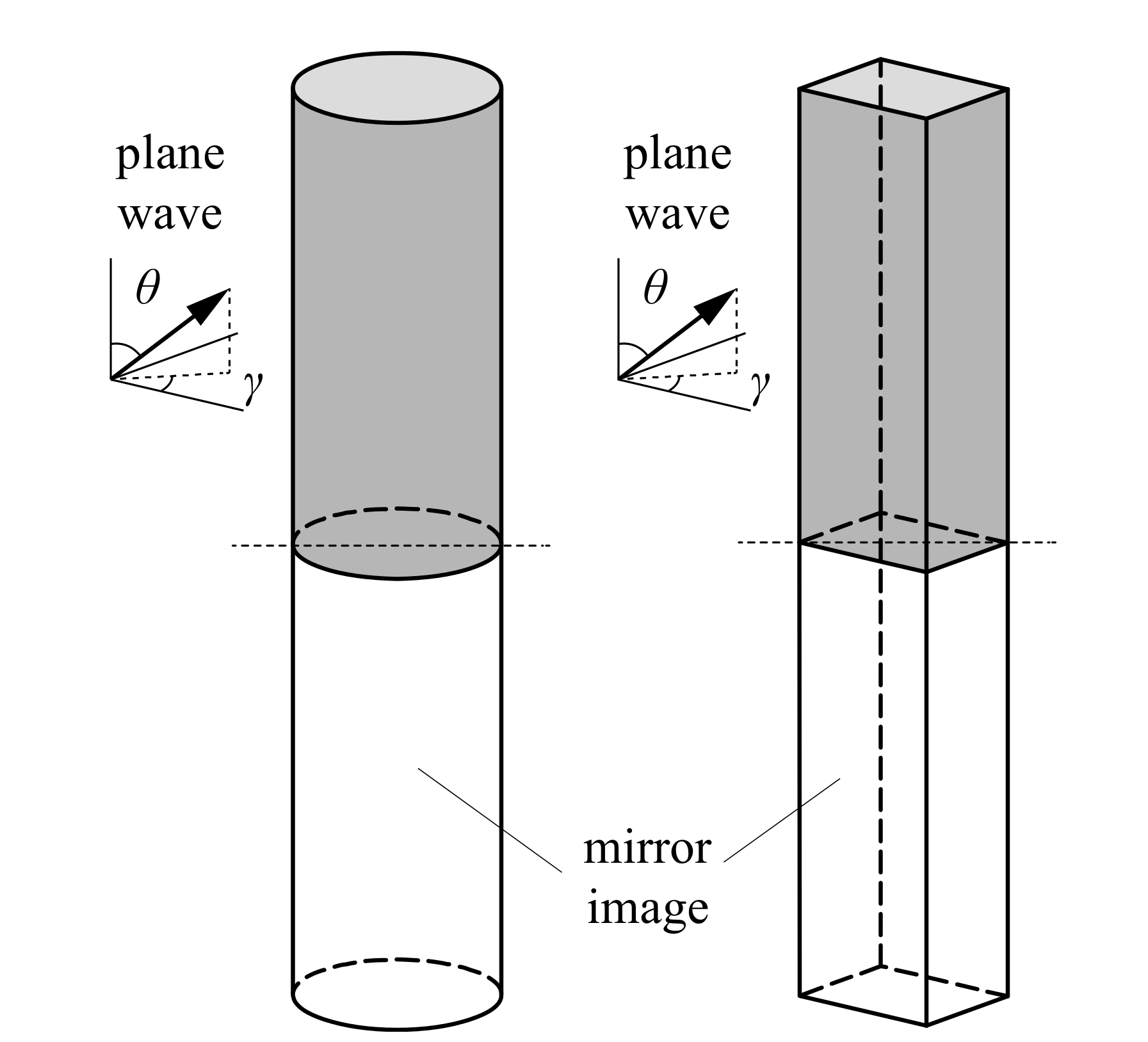
2.1. Model
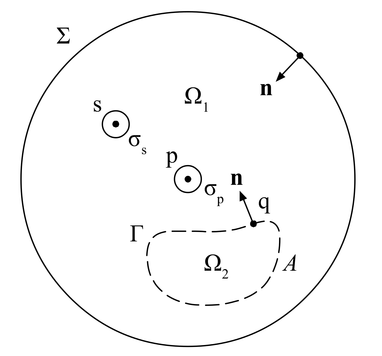
2.2. Boundary Integral Equation
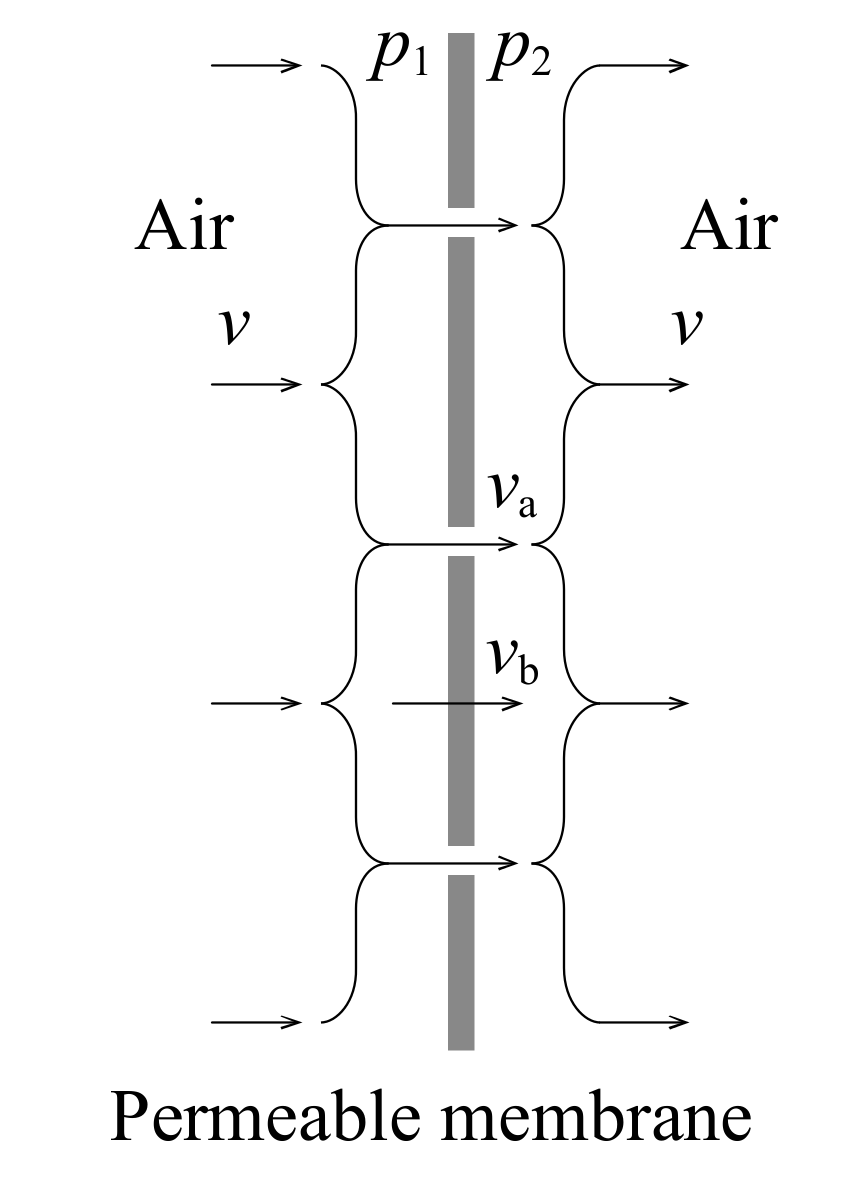
2.3. Permeable Membrane Admittance
2.4. Dissipated Energy Ratio
3. Results and Discussion
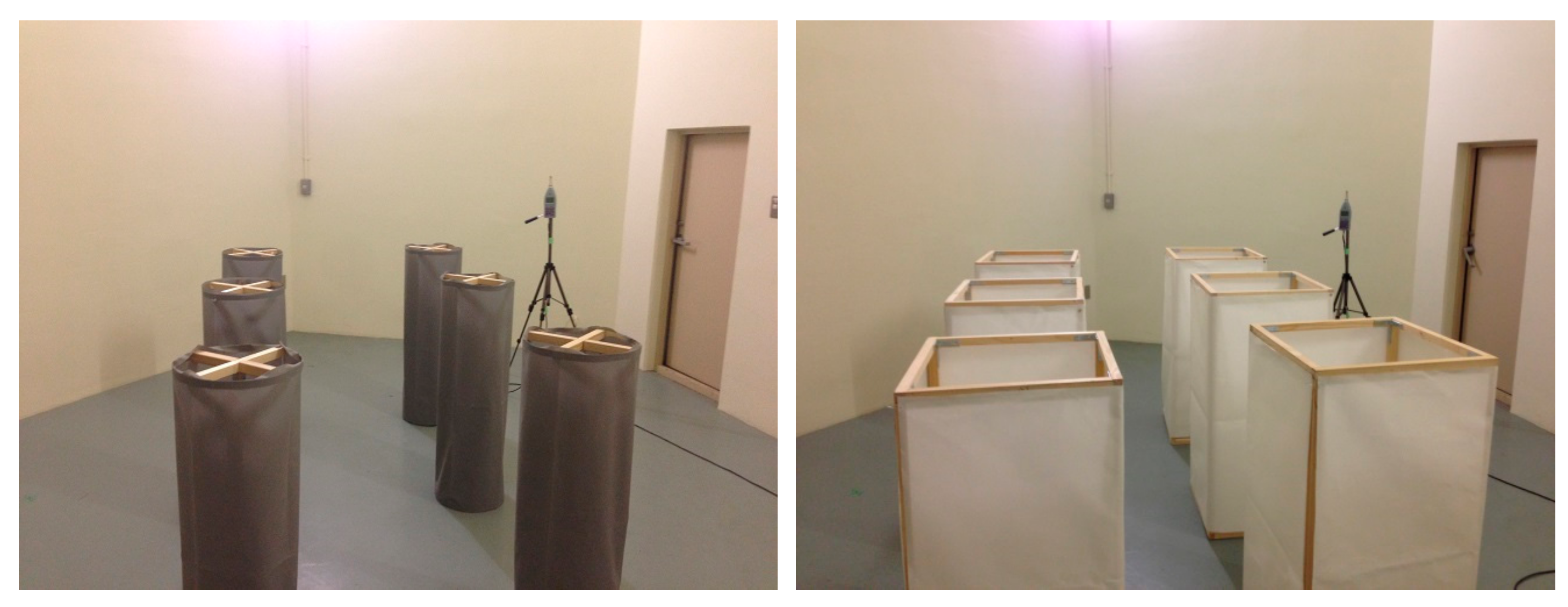
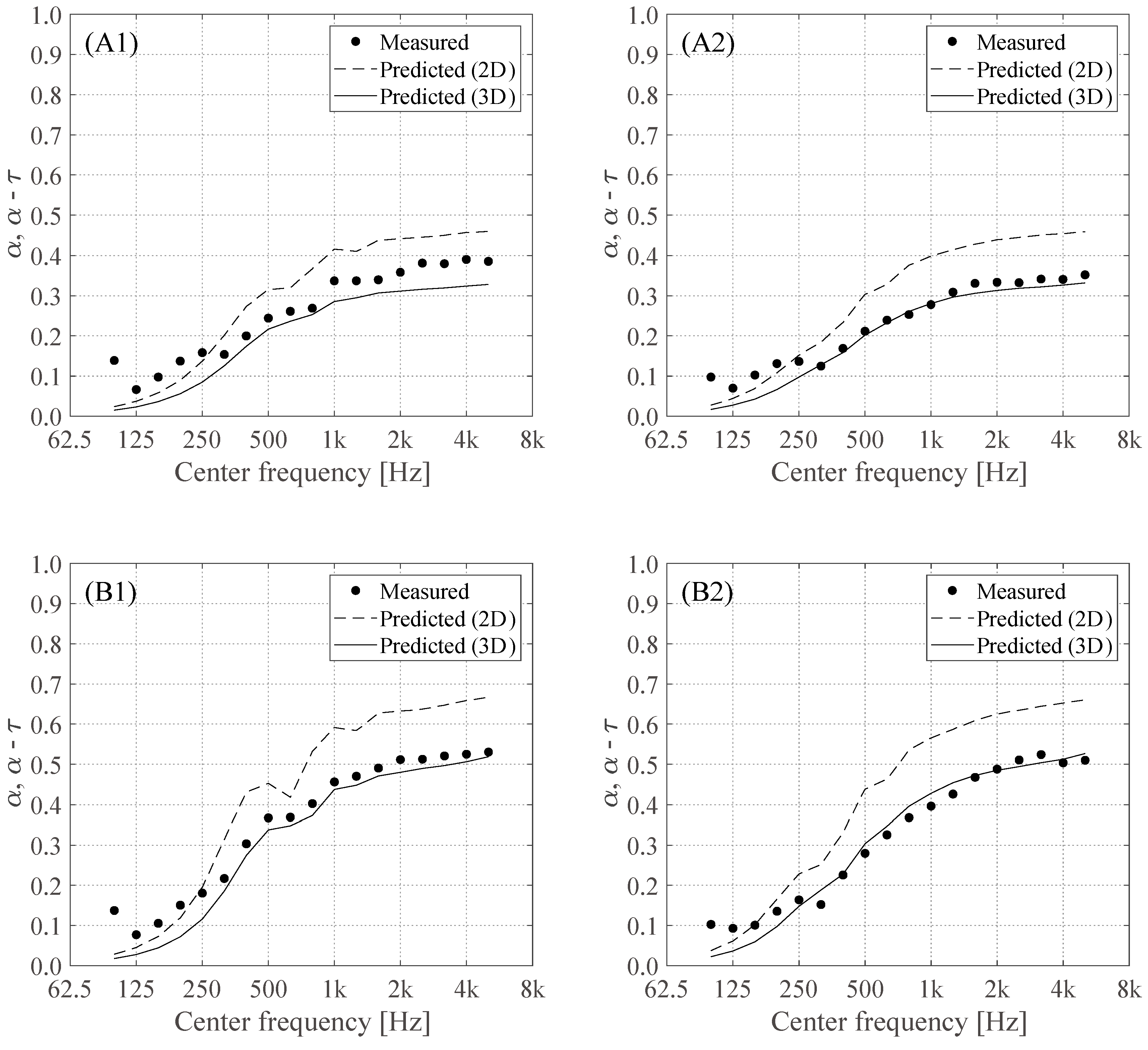
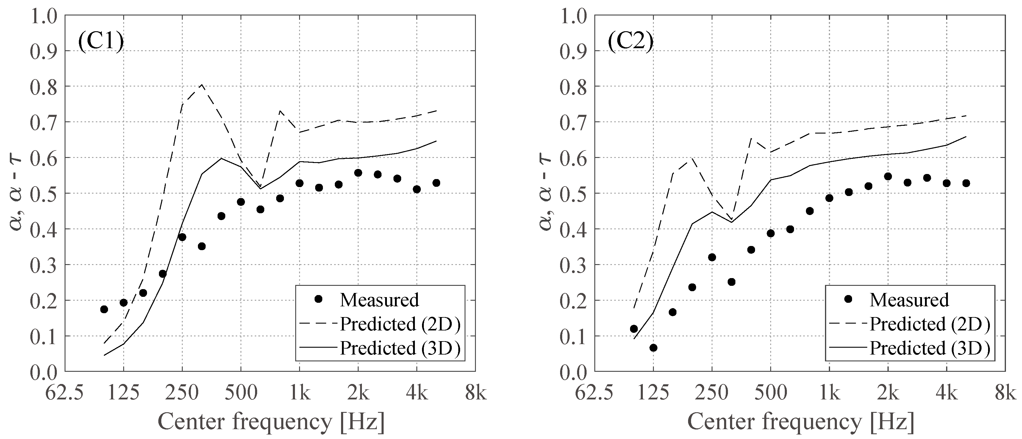
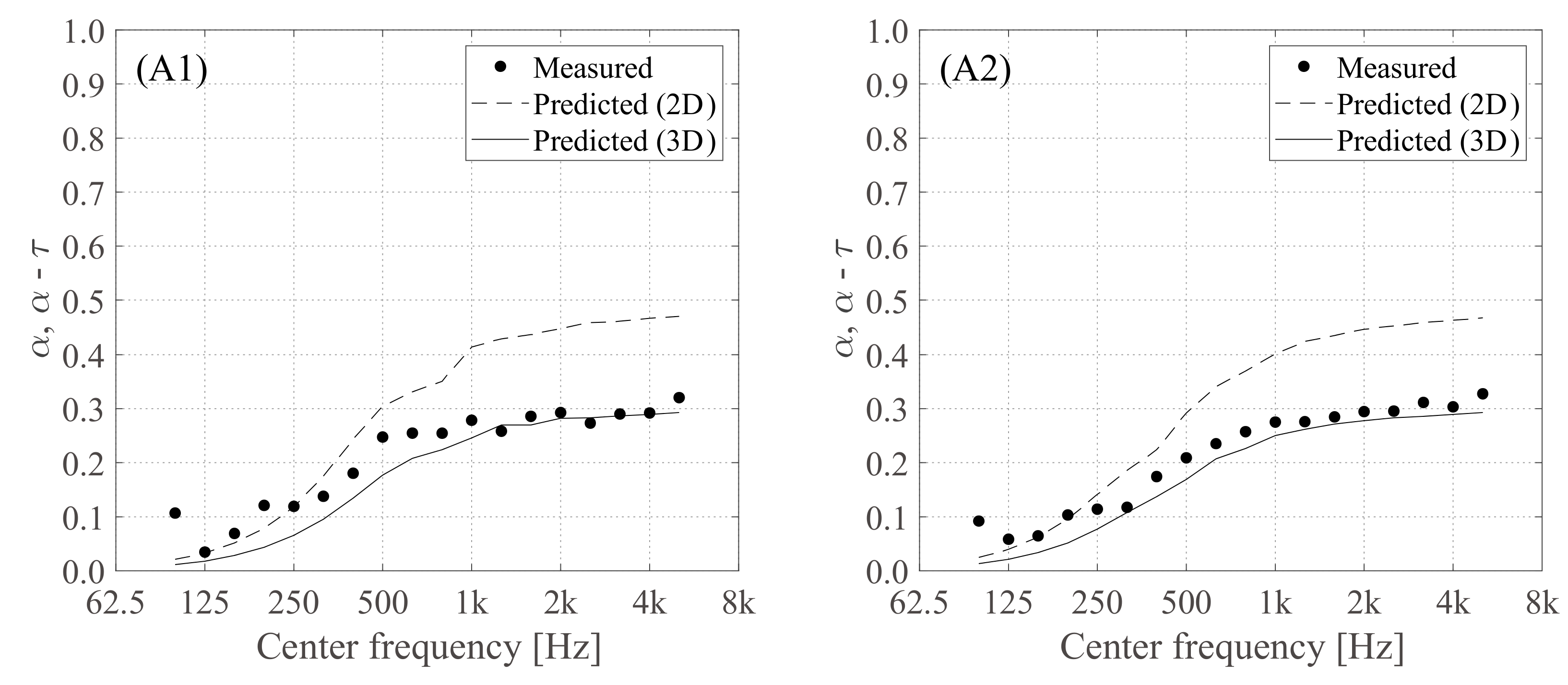
3.1. Cylindrical, Permeable Membrane Space Sound Absorber
3.2. Rectangular, Permeable Membrane Space Sound Absorber
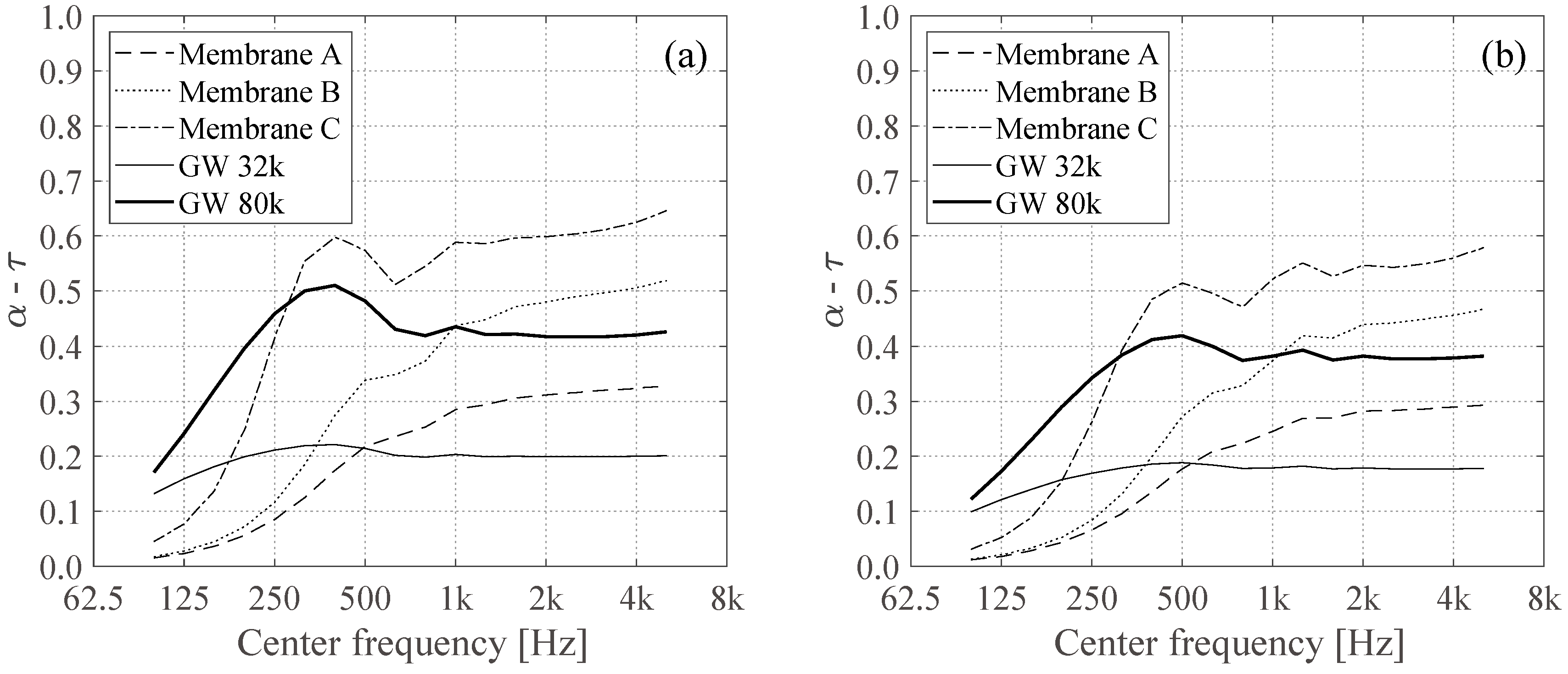
3.3. Comparison with Glass Wool
4. Conclusions
Author Contributions
Funding
Conflicts of Interest
References
- Cannistraro, G.; Cannistraro, M.; Cannistraro, A. Evaluation of the sound emissions and climate acoustic in proximity of one railway station. Int. J. Heat Technol. 2016, 34, S589–S596. [Google Scholar] [CrossRef]
- Taban, E.; Khavanin, A.; Faridan, M.; Samaei, S.E.; Samimi, K.; Rashidi, R. Comparison of acoustic absorption characteristics of coir and date palm fibers: Experimental and analytical study of green composites. Int. J. Environ. Sci. Technol. 2019, 1–10. [Google Scholar] [CrossRef]
- Berardi, U.; Iannace, G. Acoustic characterization of naturals fibers for sound absorption applications. Build. Environ. 2015, 94, 840–852. [Google Scholar] [CrossRef]
- Quintana, A.; Alba, J.; del Rey, R.; Guillen, I. Comparative life cycle assessment of gypsum plasterboard and a new kind of bio-based epoxy composite containing different natural fibers. J. Clean. Prod. 2018, 185, 408–420. [Google Scholar] [CrossRef]
- Del Rey, R.; Uris, A.; Alba, J.; Candelas, P. Characterization of sheep wool as a sustainable material for acoustic applications. Materials 2017, 10, 1277. [Google Scholar] [CrossRef] [PubMed]
- Kusno, A.; Sakagami, K.; Okuzono, T.; Toyoda, M.; Otsuru, T.; Mulyadi, R.; Kamil, K. A pilot study on the sound absorption characteristics of chicken feathers as an alternative sustainable acoustical material. Sustainability 2019, 11, 1476. [Google Scholar] [CrossRef]
- Adams, T. Sound Materials: A Compendium of Sound Absorbing Materials for Architecture and Design; Frame Pub.: New York, NY, USA, 2017. [Google Scholar]
- Fuchs, H.V. Alternative fibreglass absorbers—New tools and materials for noise control and acoustic comfort. Acta Acust. United Acust. 2001, 87, 414–422. [Google Scholar]
- Stroem, S. Orchestra enclosures and stage design in multipurpose halls used for concerts. In Proceedings of the 13th International Congress on Acoustics, Belgrade, Yugoslavia, August 1989; pp. 183–186. [Google Scholar]
- Sakagami, K.; Morimoto, M.; Takahashi, D. A note on the acoustic reflection of an infinite membrane. Acustica 1994, 80, 569–572. [Google Scholar]
- Sakagami, K.; Kiyama, M.; Morimoto, M.; Takahashi, D. Detailed analysis of the acoustic properties of a permeable membrane. Appl. Acoust. 1998, 54, 93–111. [Google Scholar] [CrossRef]
- Sakagami, K.; Kiyama, M.; Morimoto, M.; Takahashi, D. Sound absorption of a cavity-backed membrane: A step towards design method for membrane-type absorbers. Appl. Acoust. 1996, 49, 237–247. [Google Scholar] [CrossRef]
- Kiyama, M.; Sakagami, K.; Tanigawa, M.; Morimoto, M. A basic study on acoustic properties of double-leaf membranes. Appl. Acoust. 1998, 54, 239–254. [Google Scholar] [CrossRef]
- Sakagami, K.; Kiyama, M.; Morimoto, M. Acoustics properties of double-leaf membranes with a permeable leaf on sound incidence side. Appl. Acoust. 2001, 63, 911–926. [Google Scholar] [CrossRef]
- Sakagami, K.; Yoshida, K.; Morimoto, M. A note on the acoustic properties of a double-leaf permeable membrane. Acoust. Sci. Technol. 2009, 30, 390–392. [Google Scholar] [CrossRef]
- Maa, D.Y. Theory and design of microperforated panel sound-absorbing construction. Sci. Sin. 1975, 18, 55–71. [Google Scholar]
- Takahashi, D.; Tanaka, M. Flexural vibration of perforated plates and porous elastic materials under acoustic loading. J. Acoust. Soc. Am. 2002, 112, 1456–1464. [Google Scholar] [CrossRef] [PubMed]
- Wang, C.; Huang, L. On the acoustic properties of parallel arrangement of multiple micro-perforated panel absorbers with different cavity depths. J. Acoust. Soc. Am. 2011, 130, 208–218. [Google Scholar] [CrossRef] [PubMed]
- Carbajo, J.; Ramis, J.; Godinho, L.; Amado-Mendes, P.; Alba, J. A finite element model of perforated panel absorbers including viscothermal effects. Appl. Acoust. 2015, 90, 1–8. [Google Scholar] [CrossRef]
- Okuzono, T.; Sakagami, K. A frequency domain finite element solver for acoustic simulations of 3D rooms with microperforated panel absorbers. Appl. Acoust. 2018, 129, 1–12. [Google Scholar] [CrossRef]
- Okuzono, T.; Nitta, T.; Sakagami, K. Note on microperforated panel model using equivalent-fluid-based absorption elements. Acoust. Sci. Technol. 2019, 40, 221–224. [Google Scholar] [CrossRef]
- Carbajo, J.; Ramis, J.; Godinho, L.; Amado-Mendes, P. Assessment of methods to study the acoustic properties of heterogeneous perforated panel absorbers. Appl. Acoust. 2018, 133, 1–7. [Google Scholar] [CrossRef]
- Toyoda, M.; Kobatake, S.; Sakagami, K. Numerical analyses of the sound absorption of three-dimensional MPP space sound absorbers. Appl. Acoust. 2014, 79, 69–104. [Google Scholar] [CrossRef]
- Toyoda, M.; Eto, D. Prediction of microperforated panel absorbers using the finite-difference time-domain method. Wave Motion 2019, 86, 110–124. [Google Scholar] [CrossRef]
- Bolton, J.S.; Kim, N. Use of CFD to calculate the dynamic resistive end correction for microperforated materials. Acoust. Aust. 2010, 38, 134–139. [Google Scholar]
- Herdtle, T.; Bolton, J.S.; Kim, N.; Alexander, J.H.; Gerdes, R.W. Transfer impedance of microperforated materials with tapered holes. J. Acoust. Soc. Am. 2013, 134, 4752–4762. [Google Scholar] [CrossRef] [PubMed]
- Sakagami, K.; Morimoto, M.; Koike, W. A numerical study of double-leaf microperforated panel absorbers. Appl. Acoust. 2006, 67, 609–619. [Google Scholar] [CrossRef]
- Sakagami, K.; Nakamori, T.; Morimoto, M.; Yairi, M. Double-leaf microperforated panel space absorbers: A revised theory and analysis. Appl. Acoust. 2009, 70, 703–709. [Google Scholar] [CrossRef]
- Sakagami, K.; Yairi, M.; Morimoto, M. Multiple-leaf sound absorbers with microperforated panels: An overview. Acoust. Aust. 2010, 38, 64–69. [Google Scholar]
- Sakagami, K.; Nakamori, T.; Morimoto, M.; Yairi, M. Absorption characteristics of a space absorber using a microperforated panel and permeable membrane. Acoust. Sci. Technol. 2011, 32, 47–49. [Google Scholar] [CrossRef]
- Sakagami, K.; Oshitani, T.; Yairi, M.; Toyoda, E.; Morimoto, M. An experimental study on a cylindrical microperforated panel space sound absorber. Noise Control Eng. J. 2012, 60, 22–28. [Google Scholar] [CrossRef]
- Sakagami, K.; Yairi, M.; Toyoda, E.; Toyoda, M. An experimental study on the sound absorption of three-dimensional MPP space sound absorbers: Rectangular MPP space sound absorber (RMSA). Acoust. Aust. 2013, 41, 159–161. [Google Scholar]
- Fujita, S.; Sakagami, K.; Yairi, M.; Toyoda, E.; Toyoda, M. An experimental study of cylindrical micro perforated panel sound absorber with core. Noise Control Eng. J. 2013, 61, 590–596. [Google Scholar] [CrossRef]
- Sakagami, K.; Funahashi, K.; Somatomo, Y.; Okuzono, T.; Nishikawa, C.; Toyoda, M. An experimental study on the absorption characteristics of a three-dimensional permeable membrane space sound absorber. Noise Control Eng. J. 2015, 63, 300–307. [Google Scholar] [CrossRef]
- Arenas, J.P.; Crocker, M.J. Recent trend in porous sound-absorbing materials. Sound Vib. 2010, 44, 12–17. [Google Scholar]
- Sakagami, K.; Uyama, T.; Morimoto, M.; Kiyama, M. Prediction of the reverberation absorption coefficient of finite-size membrane absorbers. Appl. Acoust. 2005, 66, 653–668. [Google Scholar] [CrossRef]
- Fujiwara, K.; Makita, Y. Reverberant sound absorption coefficient of a plane space absorber. Acustica 1978, 39, 340–344. [Google Scholar]
- Baker, B.B.; Copson, E.T. The Mathematical Theory of Huygens Principle, 3rd ed.; Chelsea: New York, NY, USA, 1987. [Google Scholar]
- Terai, T. On calculation of sound fields around three dimensional objects by integral equation methods. J. Sound Vib. 1980, 69, 71–100. [Google Scholar] [CrossRef]
- Pierce, A.D. Acoustics: An Introduction to Its Physical and Applications; McGraw-Hill: New York, NY, USA, 1981; Chapters 3–8. [Google Scholar]
- Okuzono, T.; Shimizu, N.; Sakagami, K. Predicting absorption characteristics of single-leaf permeable membrane absorbers using finite element method in a time domain. Appl. Acoust. 2019, 151, 172–182. [Google Scholar] [CrossRef]


| Membrane | Surface Density [kg/m2] | Flow Resistance [Pa s/m] |
|---|---|---|
| A | 0.065 | 196 |
| B | 0.120 | 462 |
| C | 0.495 | 1087 |
© 2019 by the authors. Licensee MDPI, Basel, Switzerland. This article is an open access article distributed under the terms and conditions of the Creative Commons Attribution (CC BY) license (http://creativecommons.org/licenses/by/4.0/).
Share and Cite
Toyoda, M.; Funahashi, K.; Okuzono, T.; Sakagami, K. Predicted Absorption Performance of Cylindrical and Rectangular Permeable Membrane Space Sound Absorbers Using the Three-Dimensional Boundary Element Method. Sustainability 2019, 11, 2714. https://doi.org/10.3390/su11092714
Toyoda M, Funahashi K, Okuzono T, Sakagami K. Predicted Absorption Performance of Cylindrical and Rectangular Permeable Membrane Space Sound Absorbers Using the Three-Dimensional Boundary Element Method. Sustainability. 2019; 11(9):2714. https://doi.org/10.3390/su11092714
Chicago/Turabian StyleToyoda, Masahiro, Kota Funahashi, Takeshi Okuzono, and Kimihiro Sakagami. 2019. "Predicted Absorption Performance of Cylindrical and Rectangular Permeable Membrane Space Sound Absorbers Using the Three-Dimensional Boundary Element Method" Sustainability 11, no. 9: 2714. https://doi.org/10.3390/su11092714