Communication

Range-Gated Imaging System for Underwater Monitoring in Ocean Environment

1
DTU Aqua, National Institute for Aquatic Resources, Technical University of Denmark, Kemitorvet, 2800 Kgs. Lyngby, Denmark
2
AZTI—Marine Research, Txatxarramendi Ugartea z/g, E-48395 Sukarrieta, Spain
3
Smart Sensor Systems, SINTEF Digital, 0373 Oslo, Norway
4
SUBSEA Tech, Marine and Underwater Technologies, 13016 Marseille, France
5
Odos Imaging Ltd., Edinburgh EH16 4BB, UK
6
Bright Solutions Srl, 27010 Pavia, Italy
*
Author to whom correspondence should be addressed.
Sustainability 2019, 11(1), 162; https://doi.org/10.3390/su11010162
Submission received: 24 November 2018 / Revised: 20 December 2018 / Accepted: 22 December 2018 / Published: 29 December 2018

Abstract

:
High-quality video observations are very much needed in underwater environments for the monitoring of several ecosystem indicators and to support the sustainable development and management of almost all activities in the ocean. Reliable video observations are however challenging to collect, because of the generally poor visibility conditions and the difficulties to deploy cost-effective sensors and platforms in the marine environment. Visibility in water is regulated by natural light availability at different depths, and by the presence of suspended particles, scattering incident light in all directions. Those elements are also largely variable in time and space, making it difficult to identify technological solutions that can be used in all conditions. By combining state-of-the-art “time of flight” (ToF) image sensors and innovative pulsed laser illumination, we have developed a range-gated camera system (UTOFIA) that enables affordable and enhanced 3D underwater imaging at high resolution. This range-gated solution allows users to eliminate close-range backscattering, improving quality of the images and providing information on the distance of each illuminated object, hence giving access to real-time 3D measurements. Furthermore, as the system is based on pulsed laser light, it is almost independent of natural light conditions and can achieve similar performances at an extended depth range. We use this system to collect observations in different oceanographic conditions and for different applications, including aquaculture monitoring, seafloor mapping, litter identifications and structure inspection. Performances are evaluated by comparing images to regular cameras and by using standard targets to assess accuracy and precision of distance measurements. We suggest that this type of technology can become a standard in underwater 3D imaging to support the future development of the ocean economy.

1. Introduction

Collecting visual observations in underwater environments is a difficult task and a technological challenge [1]. Refraction, non-uniform lighting and shadows, light scattering and absorption: all reduce our ability to collect and interpret quality visual information [1,2,3]. Small suspended particles in water create a turbid environment that strongly increases light scattering and enhances the absorption probability of photons [3]. When the light source is the sun, this process effectively decreases the amount of ambient light present at any depth and limits the range of visual observations. With artificial illumination, the range for underwater vision can be extended (for example we can move deeper) but at the cost of degrading image contrast due to (forward- and back-) scattering generated by suspended particles. The situation is similar to driving a car in foggy conditions with the headlights on: increasing the power of illumination does not improve the visibility, as the backscattering increases proportionally. Image contrast is also lowered with shorter visual range as the light attenuation will reduce the illumination of distant targets. These factors remain the outstanding challenges in underwater imaging and limit the application of visual observations in many sectors [1,2,4].
Various optical and acoustic imaging systems for mitigating or solving these problems are under constant development and refinement. However, a general technological solution for high-quality images in all seawater conditions remains elusive. While acoustic methods offer the undoubted advantage to cover larger volumes of water at low resolution, optical systems are needed for habitat mapping and monitoring, as their richer data accommodates more accessible analyses, for instance in terms of species identification, enumeration, and distributions. High-definition camera sensors, improved artificial illumination systems, LIDAR sensors for bathymetry, range-gated imaging systems, and holography are all aspects in which underwater vision technology has greatly advanced in the recent years to improve coastal and open ocean habitat mapping [4,5,6,7,8,9]. Light source is often considered a critical element in these applications, and imaging systems are distinguished as passive when they rely on natural lighting, or active when artificial illumination is used. For more reliable operations at different depths and water conditions, artificial lighting is generally provided, and with the development of LED technology, several affordable solutions are becoming available for routine monitoring activities [4,5,9]. More sophisticated—but also more expensive—systems make use of laser lights to take advantage of collimated, narrow and monochromatic beams, allowing sensible reductions in scattering volumes [10,11].
Lasers can be used as continuous light sources or as strobed (pulsed) lights as in-line scanners (LIDARs) and all range-gated systems [2,10,12,
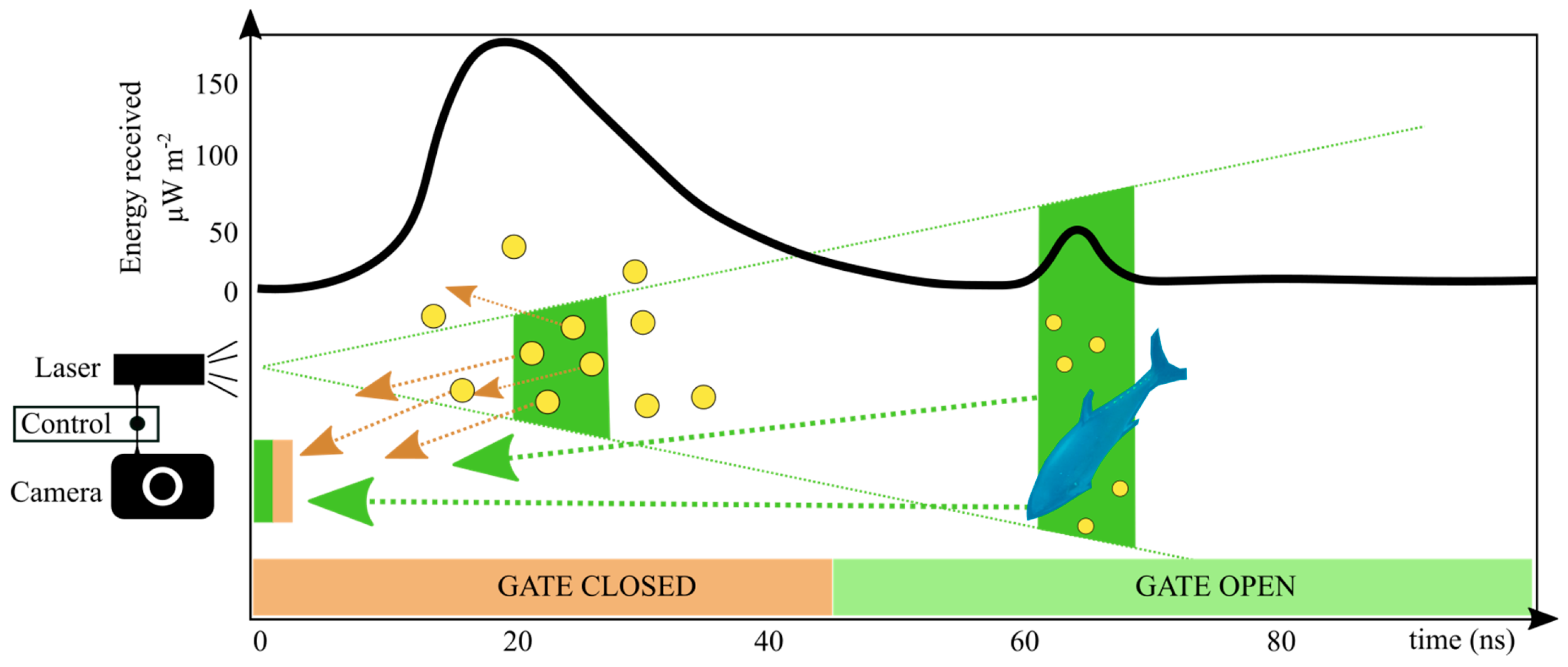
13]. Range-gated imaging systems are based on a relatively simple concept in which the camera shutter is synchronised with the light source emitting nanosecond length pulses and only opens for a time window around the instant when the signal of the illuminated object of interest reaches the camera (Figure 1). These systems can then effectively filter out forward- and back-scattering (except that within the gated time), improving visual range and augmenting image contrast [13,14]. Additionally, they can measure the time of flight (ToF) of the pulsed laser sheets, providing estimates of the distance to objects and enabling three-dimensional reconstruction of object size. The shorter the illumination pulse and image sensor gate, the finer the possible depth resolution and the more efficient the rejection of spurious backscattered light. However, notwithstanding the several advantages offered by range-gated systems with respect to other cameras, they are still limited in their use in ocean observations, since they have generally been more expensive and complex to operate, and have a limited resolution and frame-rate [13,14,15,16,17].
In this paper, we present the UTOFIA camera, an Underwater Time-Of-Flight Imaging Acquisition system capable to overcome some of present day limitations in the use of range-gated systems in oceanographic exploration. The UTOFIA consortium was created in 2015 within the European Commission Horizon 2020 framework, bringing together experts in imaging, lasers, optics, ocean science, and marine hardware. The consortium has developed a new underwater range-gated camera system which can capture high-contrast images and 3D information in a single compact video camera platform. Improved capabilities for underwater imaging is recognized as an important technological advance in the ocean economy, helping to address both environmental challenges in the sustainable use of ocean resources, and ocean related economic activities, by improving surveillance, inspection and mapping operations [18].

2. Methods

2.1. UTOFIA System

UTOFIA is an active imaging system providing 2D and 3D images covering a volume limited by the field of view and the selected distance-range interval (Figure 2, 
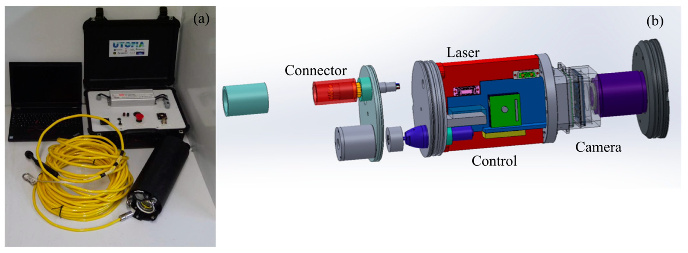
Table 1). A range from 1 to 9 m could typically be scanned in less than 1/10 s. The volume is scanned by changing the laser firing relative to the camera shutter, and three-dimensional information is extracted by processing the time scanned series of images. The system is compact and weighs 9 kg in air and less than 2 kg in water. It is composed of an integrated camera sensor and laser illumination system within a sealed and pressure-resistant cylindrical casing, which also houses the drivers for the camera and the laser, as well as the electronics needed to let these parts talk with each other; a topside command box and a cable provide power and allow data transmission (Figure 2a). The housing is composed of four parts (Figure 2b): a cylindrical shell (370 mm in length, 150 mm in diameter) made of Polyoxymethylene, the front flange (aluminium) which holds the camera and laser windows, the middle flange (aluminium) which holds the laser module, and the back flange (aluminium) which holds external connections and temperature control system. The housing has been designed to sustain 300 m water depth (30 bars). It has been tested and proven pressure resistant in a hyperbaric chamber up to 25 bars.
The topside command box includes a power supply, an Ethernet switch, a communication module, a voltmeter and an on/off switch. The power supply is adjustable with an internal potentiometer. The system’s power requirement is 200 W, delivered by 22-28 V DC. The voltage can be accommodated to compensate for voltage drop along the cable. The topside box includes a transformer for a standard 220 V power supply. Standard data communication is via a Gbit Ethernet or an optional 100 Mbit with reduced resolution and/or frame rate. A hybrid GigE RS485 70 m long umbilical can connect from the camera unit via a wet-mateable MCBH-16 connector to the topside unit, or via a 1.2 m pig-tail with a connector to an ROV or other powered platforms.

2.2. Laser Illuminator

A novel, frequency doubled laser system has been designed, manufactured and tested specifically to be used as scene illuminator in the UTOFIA project [19]. The laser is based on a miniaturised version of proprietary Q-switch technology to produce a dedicated high-power illumination source occupying a volume of less than 1.2 L. This new conceptual design consists of a frequency doubled, actively Q-switched Nd:YVO4 laser system emitting linearly polarized light pulses at 532nm, featuring a diode-pumped Master Oscillator and Power Amplifier architecture (MOPA) [20,21]. The energy, pulse duration and repetition rate are respectively >2mJ @532nm, <2ns, up to 1kHz. The laser is supplied with a diverging lens and with a set of diffusors at the exit to give a uniform intensity distribution within the field of illumination; the final beam’s divergence is approximately 6 degrees.
Efficient cooling of active laser and camera parts has allowed the system to operate at water temperatures from 0 to 20 °C without temperature stability problems. In the case of water temperatures close to 30°C, it is possible that the temperature regulation system is not sufficient to allow continuous operation at maximum power rating. Hence, for continuous operation at higher temperatures, an appropriate de-rating procedure is used either by reducing energy (i.e., 80% of maximum energy) or decreasing repetition rate (i.e., 400 to 800 Hz). A new, more sophisticated cooling system, capable of full power operation at maximum water temperature, is currently under test and will be incorporated into future UTOFIA systems.

2.3. Camera Sensors

The UTOFIA camera platform uses a monochrome CMOS time-of-flight (ToF) image sensor. The sensor has a maximum resolution of 1280 × 1024 and a frame rate which is dependent on the region of interest. At full resolution, the sensor provides a frame-rate of 400 Hz, which increases to 1000 Hz at 0.5 Mpixels. The sensor firmware includes an on-board sequencer which exposes control over the relative timing between the firing of the laser pulse and the opening of the camera shutter in increments of 1.67 ns. If the camera operates at 1000Hz and a 10Hz display frame-rate, 100 exposures are available to construct a range-gated sweep. Typically, we organize these exposures such that 25 ranges are sampled with an inter-range distance of 36 cm and an average 4 exposures at each range to improve the signal to noise. The fast shutter opens in approximately 15 ns.
To access the dual benefits of high-contrast images and 3D information, an adaptive 3D reconstruction algorithm has been developed to identify both the object distance as well as the range of optimal contrast on a per-pixel basis [22]. A final image is then reconstructed consisting of the high-contrast grey scale overlaid with the 3D information. In order to achieve this output at video rates, very efficient data processing and filtering is carried out on an internal FPGA within the operation.

2.4. Deployment and Operations

The system has been tested at sea across a broad range of weather, water and illumination conditions. In these sea trials, the system has been deployed using different platforms, ranging from simple poles, wires and bottom mounting frames, to more sophisticated vehicles such as remote operated vehicles (ROVs), unmanned surface vehicles (USVs) and benthic sledges. This versatility of deployment platforms takes advantage of the compact and relatively small dimension of the device.
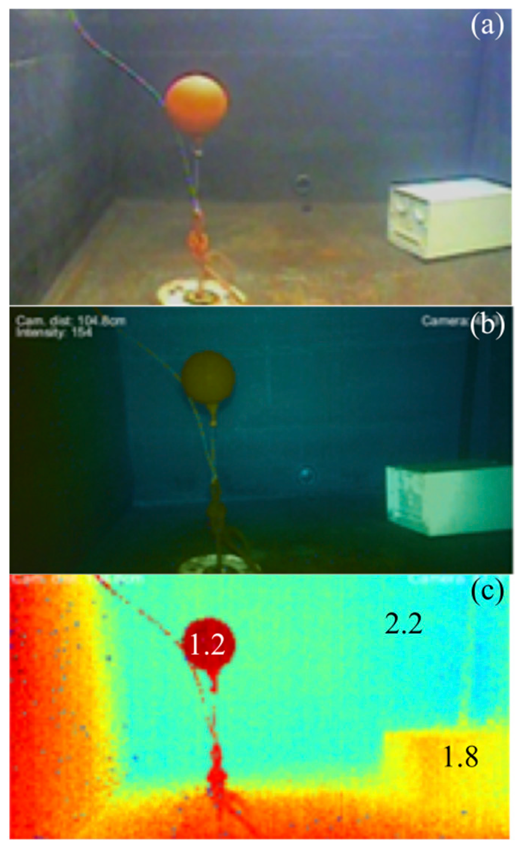
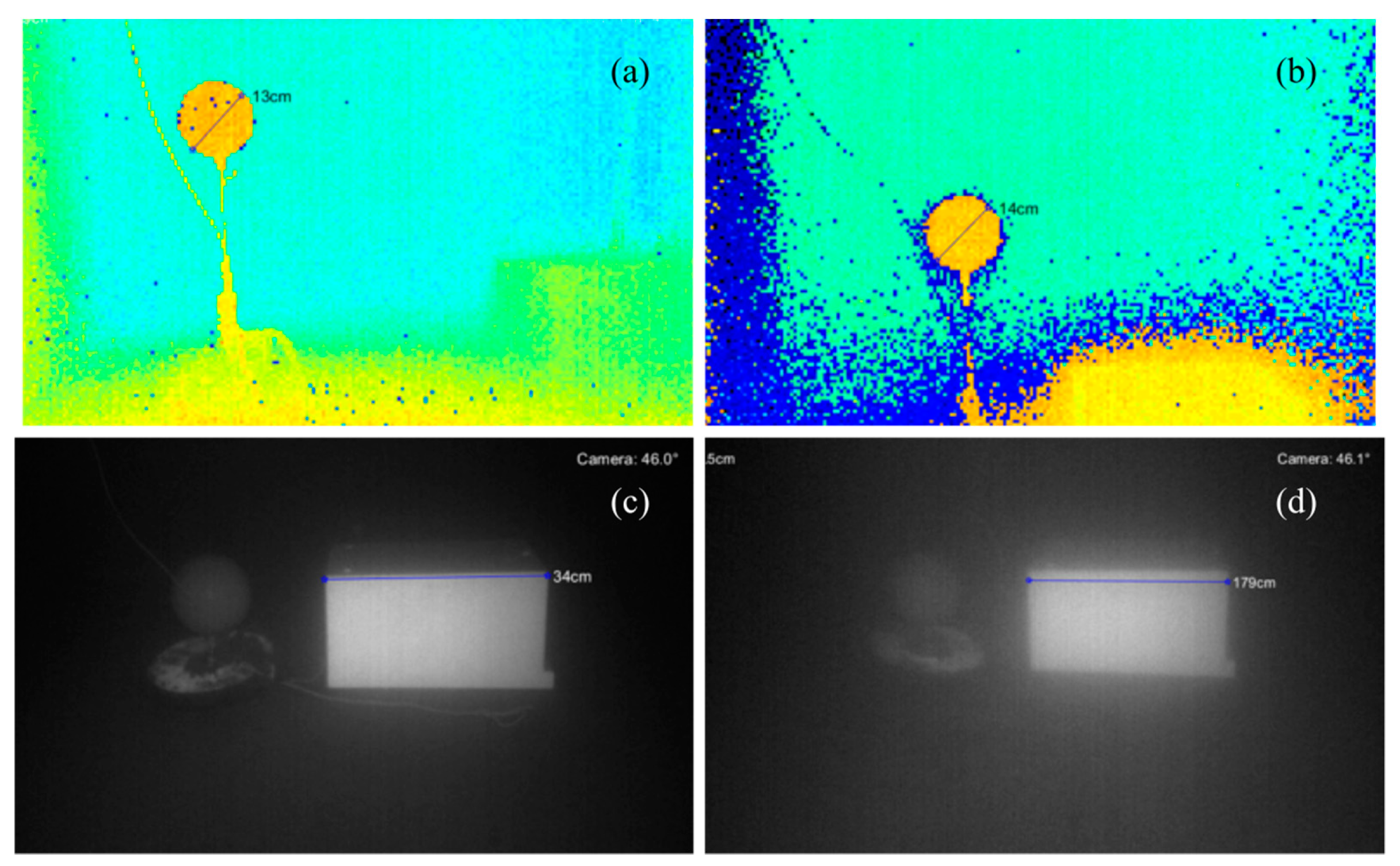
During the development phase, the system has been also extensively tested in laboratory conditions. To assess the performances at varying levels of water turbidity and different angles of view of the imaging system, we used UTOFIA in a large tank to collect images of standard targets: a buoy of size 12.7 cm (5 inches) and a white plate (34 cm × 23 cm) (Figure 3a). Turbidity has been manipulated by adding clay particles (< 0.1 mm) to the water. At a concentration of 0.1 kg m−3, the visibility in the tank was below 2 m. Attenuation length (λ) in the tank has been measured and performances of the system have been assessed in measuring the size of the different elements and in evaluating image contrast and blurring effects.

2.5. Data Processing

A software package is supplied with the system and consists of a graphical user interface (GUI) and a C# API. The GUI has been developed in MATLAB and it uses a C# API to connect and interface with the camera. The C# API is also available for the customer and can be used to develop user specific automated measurements. Through the GUI the operator is able to set operation parameters like scan range and field of view. There are several operation modes available. The user can find the best settings for their application by experimenting with the different options. Through the GUI, acquired range-gated data can be visualised, stored and processed. Length measurements can be done directly by manually selecting reference points on the screen. The GUI can also be used to re-play and post-process stored data. GUI version 1.0 (named "UTOFIA player") is available for download on the UTOFIA web site [23].

3. Results

3.1. System Performances

A range of tests have been performed in an experimental tank (Figure 3) and at sea to observe underwater objects at different underwater visibility conditions (measured with the attenuation length λ). Water turbidity and angle of view both affect the performances of the camera (Figure 4). Generally, UTOFIA is capable of imaging up to a range of approximately 4.5–5 times the attenuation length at low attenuation lengths (λ 1.5). In conditions of λ = 1.5 and λ from 2.5 to 4, we have been able to observe targets at distances of 7 m and 14 m, respectively. However, in very clear water > 4.5 λ, the water attenuation is not the limiting factor, because the laser signal will primarily drop due to radial spreading as the inverse of the distance squared. Hence, in very clear waters, the laser energy drop is the main limit for the visual range. UTOFIA is able to eliminate backscatter and obtain images with good contrast also at low λ (Figure 4). When illumination is attenuated by the water, the performance is limited by the signal to noise ratio and not backscatter. The standard deviation of the distance values in the 3D images is estimated to be 1–2 cm up to 3 λ for a white target. At 14 m range, an average distance variation of 10 cm for a white target was observed.

3.2. Observations at Sea

The reduced influence from backscatter in UTOFIA system improves the possibilities for working in murky water close to the sea bottom where there is namely a need for detailed and effective monitoring of benthic habitats, animals or marine litter (Figure 5). The system produces videos at 10 Hz providing dynamic observations of fish schools (Figure 6). Combining distance measurements and intensity image, it is possible to separate individuals even in dense schools of fish and automatically discriminate one fish from another (Figure 6 and Figure 7). It is interesting to note that while collecting observations of underwater vehicles at night in the Copenhagen harbour (Figure 7a,c) the tether of the ROV of diameter ca. 0.5 cm was clearly visible and measurable at a distance of more than 4 m. This confirms the high accuracy and precision of the system already identified in laboratory tests. These capabilities can allow for better species identification and augmented habitat monitoring in almost all marine environment from coastal to open ocean.

3.3. Fish size and Tracking

The UTOFIA system can measure the distance of objects in the images. Combining the distance information with known pixel resolution, one can easily measure the size of the objects in the field of view of the camera (Figure 8). This 3D feature not only has several potential applications in the aquaculture sector, but it can also contribute to improved monitoring and surveillance of many other underwater activities. An example of 3D measurements in aquaculture is provided by the capacity of the UTOFIA system to collect observations of Atlantic bluefin tuna in a fish farm in Spain (Figure 9). From the three-dimensional reconstruction of the image, weight distribution of the fish in the cage can be estimated allowing for better management of feed provision and harvesting schedules. Combined with external information about the number of fish deployed, this can provide continuously updated information on total biomass. Additionally, the improved capabilities of the UTOFIA system in providing better contrast and simultaneous information on object backscatter intensity and distance, allows for improved segmentation of the images and more efficient computer vision applications. For example, when observing fish schools (Figure 10) this allows the fish to be individually sized and tracked over time, recovering movement trajectories and estimating swimming performances. These capabilities of the system can be used in marine science and in aquaculture, but also contribute with new opportunities in fisheries science and technology.

4. Discussion

4.1. Surveying the Ocean

Surveying the ocean is a prerequisite for the safe and sustainable use of marine resources [24]. Traditional fishing activities, the rapid development of underwater renewable energy plants, the expansion of fish farms and the increasing requirements for surveying ageing infrastructures (e.g., dams, water reservoirs, harbour facilities); all call for rapid technological advances in underwater observation technologies. For example, in fisheries and aquaculture, there is a need of high quality and real-time data on, namely, fish abundances and size, as well as identification of marine habitat status, to achieve the sustainable management of these resources [25,26,27]. Food supply from the ocean now contribute more than 15% of the overall amount of animal protein consumed worldwide [28], hence it is essential for human health and wellbeing that these resources are managed at sustainable levels.
However, observations in underwater environment are technologically challenging given the extreme visibility conditions. At large distances, sonar is the predominant technology for observing the subsurface oceans, but while it can be applied at close range, its restricted resolution and high cost strongly limits its usefulness. Video cameras are the primary sensor technology for detailed underwater observations due to their lower cost and higher resolution. They are especially valuable when direct visualization is required, for example for species identification, habitat mapping, inspecting subsurface structures. The major drawback of any underwater optical technique such as conventional video cameras is their severe limitation in turbid waters, where light scattering reduces the range and quality of image data.
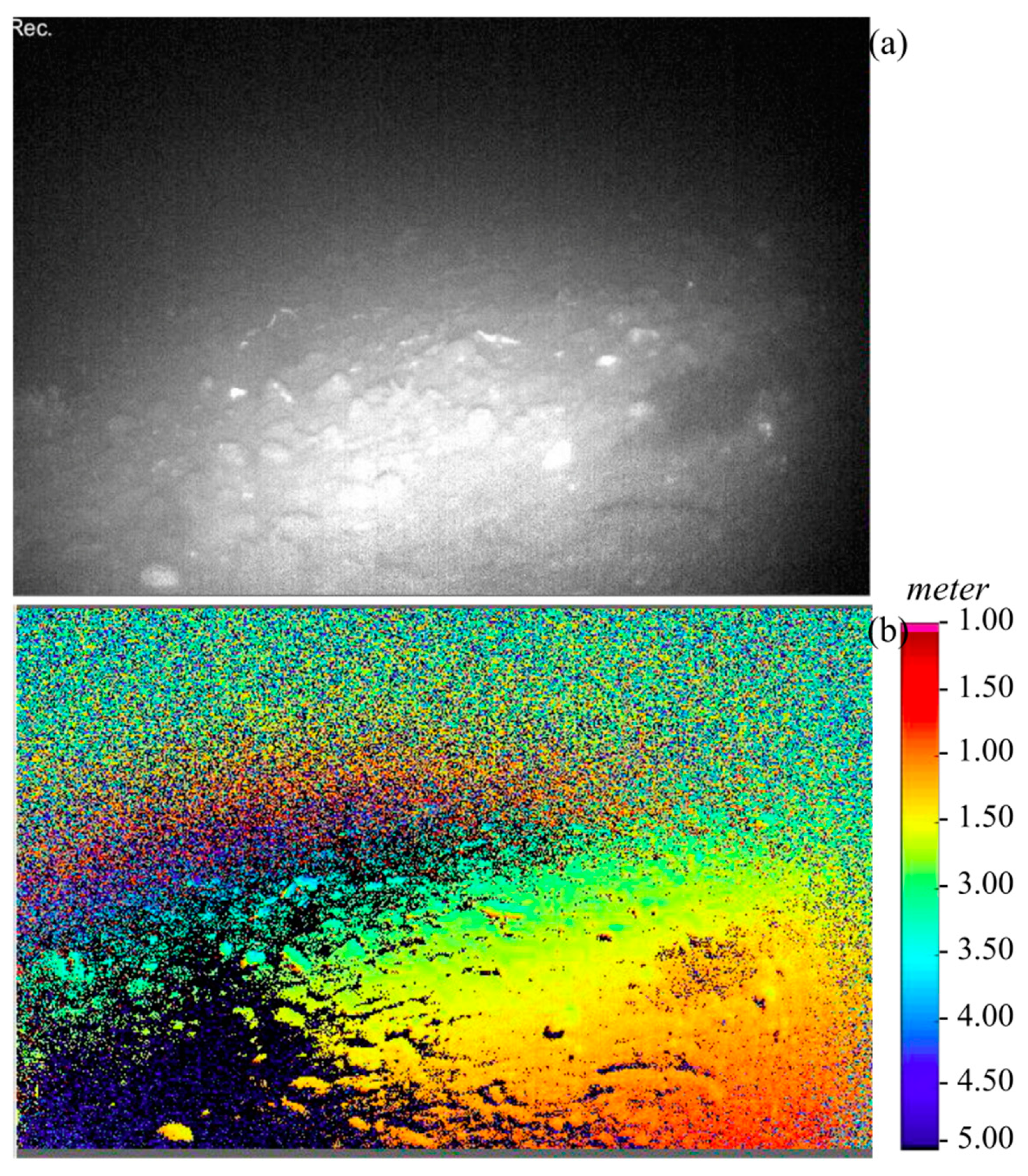
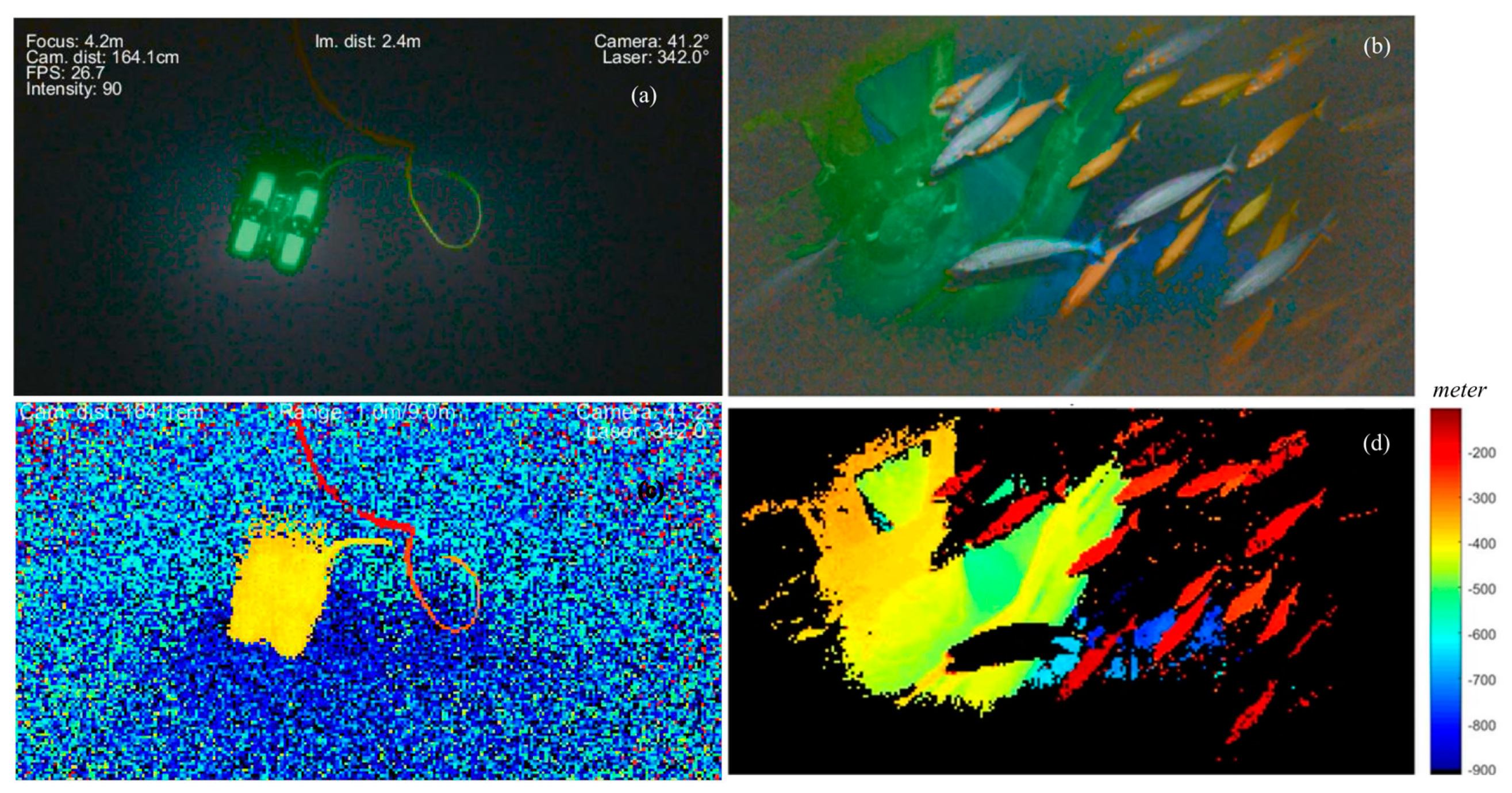
The UTOFIA system presented in this paper can overcome the limitations created by scattering, by introducing cost-efficient range-gated imaging for underwater applications. Combining pulsed laser light and a range-gated camera system, the UTOFIA can perform observations in turbid environments, improving image contrast and quality with respect to standard underwater cameras. Additionally, the system can provide three-dimensional information of underwater objects to augment the images with data on size and to improve performances of computer vision algorithm applied to those images. Applications such as those presented here can help different maritime sectors to introduce cost effective solutions for monitoring, inspection and surveillance.
The main advantage of the UTOFIA system compared to competing systems such as the Laser Underwater Camera Image Enhancer (LUCIE [14]) is that it is a cost-effective high-resolution integrated system. It uses the range-gating concept for high-precision 3D acquisition and the 3D data is used to automatic determine the optimal range for contrast enhanced imaging. In comparison, the LUCIE system [14] is only capable of performing contrast enhancing range gating and requires an expensive sonar for automatic guiding of the ideal gating distance [29]. However, LUCIE uses an expensive image intensifier in combination with a CCD camera to makes it more light sensitive compared to UTOFIA. The result is that it can detect objects at further distances than UTOFIA (approximately 6x the attenuation length for LUCIE versus 5x for UTOFIA at λ 1 ).

4.2. Improving Management of Marine Resources

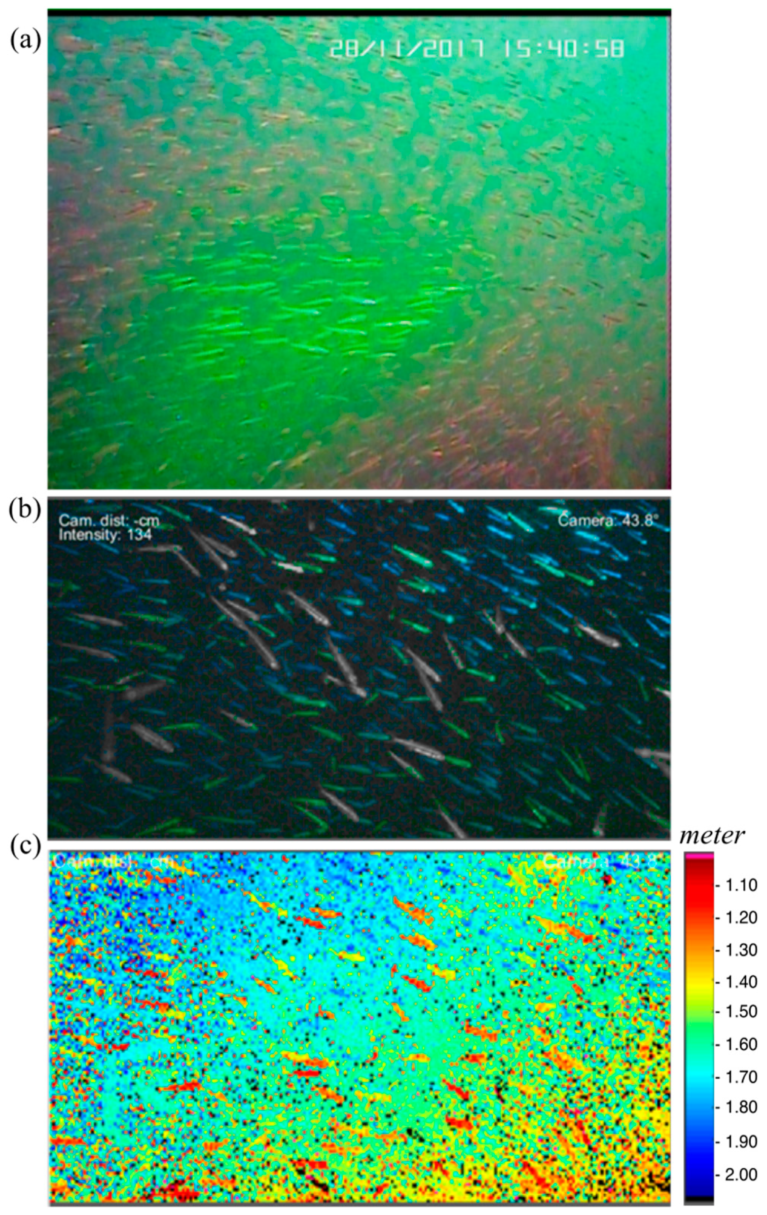
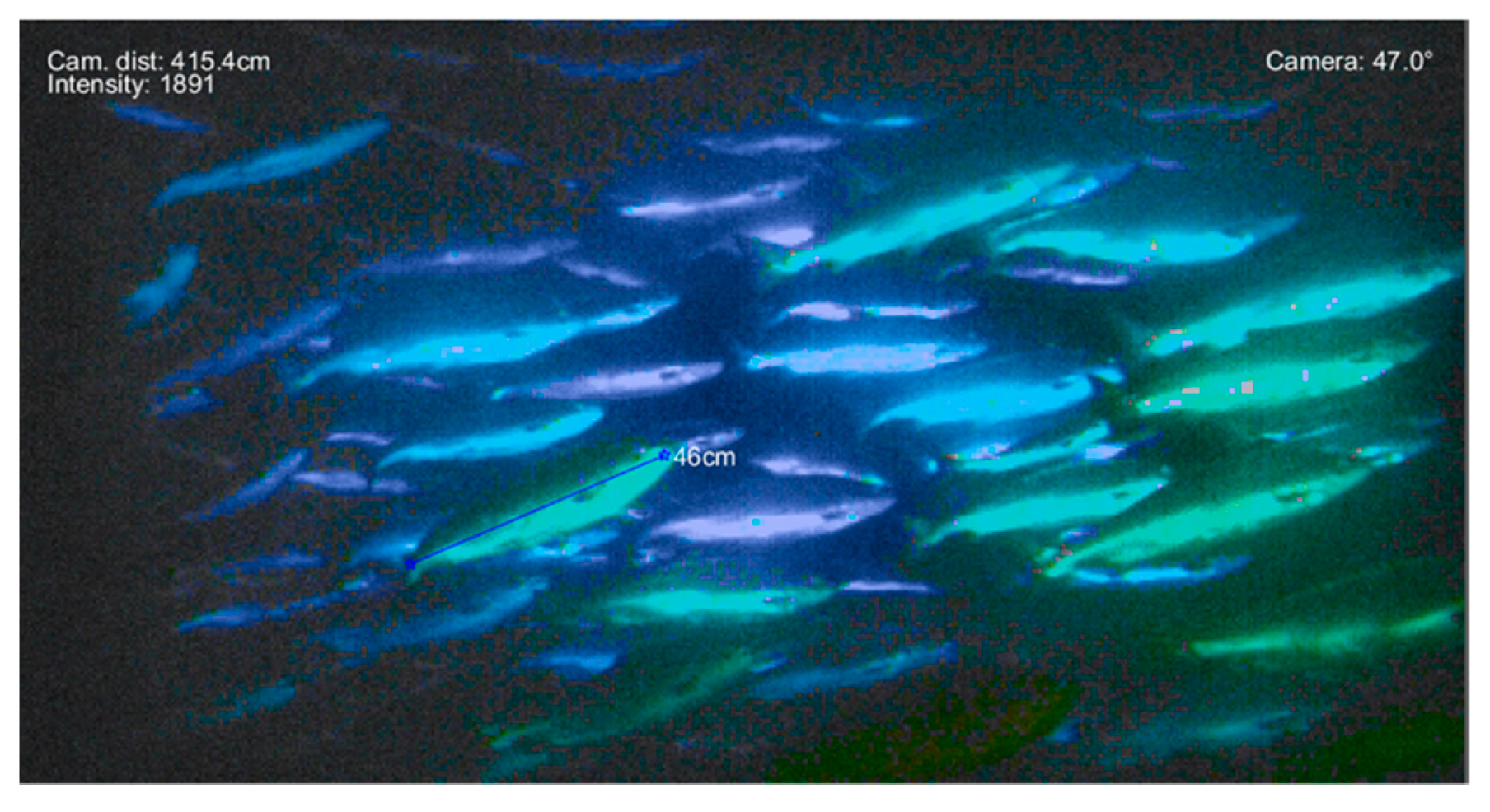
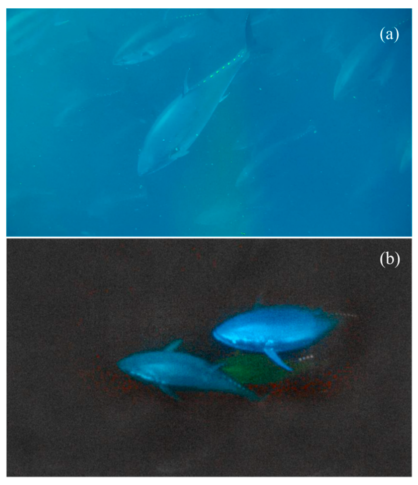
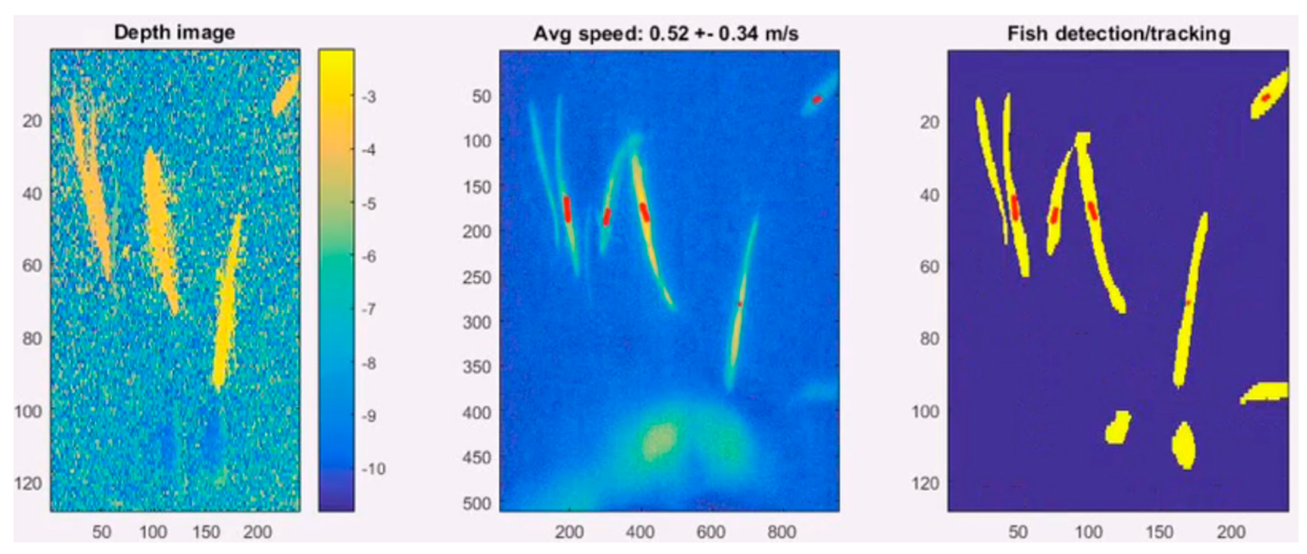
Marine resource management depends not only on counting species, but also assessing size and abundance. The ability of the UTOFIA system to capture dynamic scenes has been tested in sea trials and laboratory setups. In several laboratory trials, fish have been released in a tank and the UTOFIA system has been used to measure the distance to each fish. The live 3D images captured at 10 Hz allow for immediate visualization of the fish in a 3D volume together with an intensity image; it also allows for hundreds of fish to be measured in a few minutes. This has great potential application to optimize the management of aquaculture productions, reducing unnecessary feed waste and observing growing conditions in the cages.
Surveying the ocean bottom, removing marine litter from the seabed or evaluating impact of human activities on natural habitats typically require the extensive use of underwater vehicles (AUVs, ROVs, etc.). The limited imaging range of conventional video cameras in low visibility waters requires that these platforms be deployed very close to the bottom during the survey, thus observing just a small part of the seabed. By extending the imaging range, UTOFIA can allow such operations to become safer and faster. Given the compact and relatively small size of the system, it is designed to be deployed on several autonomous platforms. Tests on different ROVs have been performed allowing safer navigation (e.g., avoid bottom collisions) and larger image footprint during data collection at the bottom. Additionally, given the improved image contrast and augmented information on sizes, automatic classification of habitat feature can be optimized using the UTOFIA images.

4.3. Advance Marine Science

Traditionally, the use of visualization systems within marine sciences span from the smallest individuals (zooplankton) to fish and mammals, as well as mapping and monitoring the physical marine habitat. Applications are for the large part used within the field of behavioral studies, ecosystem monitoring, direct observations of subsea processes, mapping sea beds, and surveying habitats [30,31,32]. More elaborate experiments seek to quantify fish behavior (e.g., swimming speed, schooling, feeding) both in the field and under controlled conditions as functions of environmental conditions (e.g., light levels, turbulence, current speed, turbidity). Observations of these phenomena at sea are extremely challenging given the highly dynamic environment and poor visibility conditions underwater. The UTOFIA system demonstrated the capacity to determine the size of organisms and how they move relative to each other; this can open ways of better understanding complex processes such as school formation or social structures in fish groups. The ability to follow individual fish and determine their swimming characteristics can also allow to study interactions between fish and underwater structures such as reef, harbor constructions or offshore windmill installations. The UTOFIA might become a new asset of the coastal ocean observation systems [33].

5. Conclusions

UTOFIA is a compact underwater active imaging system with integrated laser illumination and range-gated technology, used to provide visual images and high-resolution 3D data. The range-gated imaging technology reduces the backscattering effects from suspended matter and improve image quality and contrast. Three dimensional capabilities enable the accurate size measurement of underwater objects in the field of view of the camera. The unique capabilities of UTOFIA make it suitable for a broad range of professional, commercial and industrial use in underwater operations, providing a number of new tools for augmented observations. These capabilities of the system can be used in marine science and in aquaculture, but also contribute with new opportunities across a broad range of maritime activities from fisheries to off-shore industry. The LIDAR technology used in UTOFIA also has applications beyond subsea usage, and in the future, we will explore the possibilities to deploy the system for space rendezvous and docking applications.

Author Contributions

All Authors have contributed to the study. J.T.T. supervised the construction and testing of the UTOFIA camera and was coordinator of the project with technical support of K.H.H. and P.R., G.P. and G.R. developed the laser. C.Y. developed the camera sensor. I.Q., P.M., Y.C. and A.W.V. tested the system. M.P. wrote the initial draft of the manuscript with the contribution of all Authors.

Funding

This research was funded by EU Horizon 2020 project UTOFIA (www.utofia.eu), grant No. 633098. Orients Fund support the project SENTINEL for additional sea trials on ROVs.

Acknowledgments

We are very grateful to Ricardo Fuentes e Hijos, S.A to make available its facilities in Cartagena (Spain) while filming red tuna in open sea cages; special thanks to the crew of the vessel and the scuba divers team.

Conflicts of Interest

The authors declare no conflict of interest.

References

  1. Jaffe, J.S.; Moore, K.D.; McLean, J.; Strand, M.P. Underwater Optical Imaging: Status and Prospects. Oceanography 2001, 14, 64–75. [Google Scholar] [CrossRef] [Green Version]
  2. Bonin-Font, F.; Burguera, A.; Oliver, G. New Solutions in Underwater Imaging and Vision Systems. Imaging Mar. Life Macrophotogr. Microsc. Approaches Mar. Biol. 2013, 22–47. [Google Scholar]
  3. Jerlov, N.G.; Nielsen, E.S. Optical Aspects of Oceanography; Academic press: Cambridge, MA, USA, 1975. [Google Scholar]
  4. Kocak, D.M.; Dalgleish, F.R.; Caimi, F.M.; Schechner, Y.Y. A Focus on Recent Developments and Trends in Underwater Imaging. Mar. Technol. Soc. J. 2008, 42, 52–67. [Google Scholar] [CrossRef]
  5. Hou, W.; Gray, D.J.; Weidemann, A.D.; Fournier, G.R.; Forand, J.L. Automated Underwater Image Restoration and Retrieval of Related Optical Properties; IEEE: New York, NY, USA, 2007. [Google Scholar]
  6. Alfalou, A.; Brosseau, C. Recent Advances in Optical Image Processing. In Progress in Optics; Elsevier: Amsterdam, The Netherlands, 2015; Volume 60, pp. 119–262. [Google Scholar]
  7. Feygels, V.; Aitken, J.; Ramnath, V.; Duong, H.; Marthouse, R.; Smith, B.; Clark, N.; Renz, E.; Reisser, J.; Kopilevich, Y. Coastal Zone Mapping and Imaging Lidar (CZMIL) Participation in the Ocean Cleanup’s Aerial Expedition Project. In Proceedings of the OCEANS-Anchorage 2017, Anchorage, AK, USA, 18–21 September 2017; pp. 1–7. [Google Scholar]
  8. Tuell, G.; Barbor, K.; Wozencraft, J. Overview of the Coastal Zone Mapping and Imaging Lidar (CZMIL): A New Multisensor Airborne Mapping System for the US Army Corps of Engineers. In Algorithms and Technologies for Multispectral, Hyperspectral, and Ultraspectral Imagery XVI; SPIE Press: Bellingham, WC, USA, 2010; p. 76950R. [Google Scholar]
  9. Howland, J.; Farr, N.; Singh, H. Field Tests of a New Camera/Led Strobe System. In Proceedings of the OCEANS 2006, Boston, MA, USA, 18–21 September 2006; pp. 1–4. [Google Scholar]
  10. Massot-Campos, M.; Oliver-Codina, G. Optical Sensors and Methods for Underwater 3D Reconstruction. Sensors 2015, 15, 31525–31557. [Google Scholar] [CrossRef] [PubMed] [Green Version]
  11. O’Toole, M.; Achar, S.; Narasimhan, S.G.; Kutulakos, K.N. Homogeneous Codes for Energy-Efficient Illumination and Imaging. ACM Trans. Graph. (ToG) 2015, 34, 35. [Google Scholar] [CrossRef]
  12. Palomer, A.; Ridao, P.; Youakim, D.; Ribas, D.; Forest, J.; Petillot, Y. 3D Laser Scanner for Underwater Manipulation. Sensors 2018, 18, 1086. [Google Scholar] [CrossRef] [PubMed]
  13. Swartz, B.A. Laser Range Gate Underwater Imaging Advances. In Proceedings of the Oceans Engineering for Today’s Technology and Tomorrow’s Preservation (OCEANS’94), Brest, France, 13–16 September 1994; Volume 2, pp. II–722. [Google Scholar]
  14. Weidemann, A.; Fournier, G.R.; Forand, L.; Mathieu, P. In Harbor Underwater Threat Detection/Identification Using Active Imaging. Photonics Port Harbor Secur. 2005, 5780, 59–71. [Google Scholar]
  15. Busck, J.; Heiselberg, H. Gated Viewing and High-Accuracy Three-Dimensional Laser Radar. Appl. Opt. 2004, 43, 4705–4710. [Google Scholar] [CrossRef] [PubMed]
  16. Andersen, J.F.; Busck, J.; Heiselberg, H. Submillimeter 3-D Laser Radar for Space Shuttle Tile Inspection; Danisch Defense Research Establishment: Copenhagen, Denmark, 2013. [Google Scholar]
  17. Tan, C.; Seet, G.; Sluzek, A.; He, D. A Novel Application of Range-Gated Underwater Laser Imaging System (ULIS) in near-Target Turbid Medium. Opt. Lasers Eng. 2005, 43, 995–1009. [Google Scholar] [CrossRef]
  18. OECD. The Ocean Economy in 2030; OECD Publishing: Paris, France, 2016. [Google Scholar]
  19. Cametti, E.; Dell’Acqua, S.; Farinello, P.; Piccinno, G.; Reali, G. UTOFIA Project: A Novel MOPA Laser Source for a Compact, Cost-Effective System for Underwater Range-Gated Imaging. In Proceedings of the 18th Italian National Conference on Photonic Technologies (Fotonica 2016), Rome, Italy, 6–8 June 2016. [Google Scholar]
  20. Paschotta, R. Master Oscillator Power Amplifier. In Encyclopedia of Laser Physics and Technology; Wiley-VCH: Weinheim, Germany, 2008; Volume 1, ISBN 978-3-527-40828-3. [Google Scholar]
  21. Koechner, W.; Bass, M. Solid-State Lasers: A Graduate Text; Springer Science & Business Media: Berlin, Germany, 2006. [Google Scholar]
  22. Risholm, P.; Thorstensen, J.; Thielemann, J.T.; Kaspersen, K.; Tschudi, J.; Yates, C.; Softley, C.; Abrosimov, I.; Alexander, J.; Haugholt, K.H. Real-Time Super-Resolved 3D in Turbid Water Using a Fast Range-Gated CMOS Camera. Appl. Opt. 2018, 57, 3927–3937. [Google Scholar] [CrossRef] [PubMed]
  23. A New, Compact and Cost-Efficient Concept for Underwater Range-Gated Imaging System. Available online: www.utofia.eu (accessed on 28 December 2018).
  24. Steffen, W.; Richardson, K.; Rockström, J.; Cornell, S.E.; Fetzer, I.; Bennett, E.M.; Biggs, R.; Carpenter, S.R.; De Vries, W.; De Wit, C.A.; Folke, C. Planetary Boundaries: Guiding Human Development on a Changing Planet. Science 2015, 347, 1259855. [Google Scholar] [CrossRef] [PubMed]
  25. Føre, M.; Frank, K.; Norton, T.; Svendsen, E.; Alfredsen, J.A.; Dempster, T.; Eguiraun, H.; Watson, W.; Stahl, A.; Sunde, L.M.; Schellewald, C. Precision Fish Farming: A New Framework to Improve Production in Aquaculture. Biosyst. Eng. 2017, 173, 176–193. [Google Scholar] [CrossRef]
  26. Siddiqui, S.A.; Salman, A.; Malik, M.I.; Shafait, F.; Mian, A.; Shortis, M.R.; Harvey, E.S. Handling editor: Howard Browman. Automatic Fish Species Classification in Underwater Videos: Exploiting Pre-Trained Deep Neural Network Models to Compensate for Limited Labelled Data. ICES J. Mar. Sci. 2017, 75, 374–389. [Google Scholar] [CrossRef]
  27. Muñoz-Benavent, P.; Andreu-García, G.; Valiente-González, J.M.; Atienza-Vanacloig, V.; Puig-Pons, V.; Espinosa, V. Handling editor: Howard Browman. Automatic Bluefin Tuna Sizing Using a Stereoscopic Vision System. ICES J. Mar. Sci. 2017, 75, 390–401. [Google Scholar] [CrossRef]
  28. Food and Agriculture Organization of the United Nation (FAO). The State of World Fisheries and Aquaculture 2018—Meeting the Sustainable Development Goals; Food and Agriculture Organization of the United Nation: Rome, Italy, 2018; p. 210. [Google Scholar]
  29. Church, P.; Hou, W.; Fournier, G.; Dalgleish, F.; Butler, D.; Pari, S.; Jamieson, M.; Pike, D. Overview of a Hybrid Underwater Camera System. In Ocean Sensing and Monitoring VI; 2014; Volume 9111, p. 91110O. [Google Scholar]
  30. Dell, A.I.; Bender, J.A.; Branson, K.; Couzin, I.D.; de Polavieja, G.G.; Noldus, L.P.; Pérez-Escudero, A.; Perona, P.; Straw, A.D.; Wikelski, M.; et al. Automated Image-Based Tracking and Its Application in Ecology. Trends Ecol. Evol. 2014, 29, 417–428. [Google Scholar] [CrossRef] [PubMed]
  31. Pérez-Escudero, A.; Vicente-Page, J.; Hinz, R.C.; Arganda, S.; De Polavieja, G.G. IdTracker: Tracking Individuals in a Group by Automatic Identification of Unmarked Animals. Nat. Methods 2014, 11, 743. [Google Scholar] [CrossRef] [PubMed]
  32. Kenny, A.J.; Cato, I.; Desprez, M.; Fader, G.; Schüttenhelm, R.T.E.; Side, J. An Overview of Seabed-Mapping Technologies in the Context of Marine Habitat Classification. ICES J. Mar. Sci. 2003, 60, 411–418. [Google Scholar] [CrossRef]
  33. Liu, Y.; Kerkering, H.; Weisberg, R.H. Coastal Ocean Observing Systems; Academic Press: Cambridge, MA, USA, 2015. [Google Scholar]
Figure 1. Range-gated imaging system. A laser pulse (green areas) illuminates underwater objects at different times, and hence different distances. Suspended particles (yellow dots) will contribute to backscatter (arrows) with the largest energy signal on the camera coming from close range particles (black line). In range-gated systems, the shutter on the camera is only open for a narrow time window away from the backscatter region. In this example, the camera is closed for about 45 ns, thus only objects farther than about 5 m are detected (e.g., such as the tuna at about 8 m distance). This improves the signal-to-noise ratio as, in general, the intensity of particle scattering in the detection region is less than the total energy reflected by the object of interest, in this case the fish.
Sustainability 11 00162 g001
Figure 2. UTOFIA camera system (a) topside box, control computer, laser camera, connecting cable. (b) Technical drawing of the UTOFIA system with back flange and hermetic connector, the laser with power and control electronics ending on a middle flange where the camera is positioned. The housing has a diameter of 155 mm and a length of 370 mm, with a total volume of 7 L, and is designed to withstand the pressure up to 300 meter depth.
Sustainability 11 00162 g002
Figure 3. Laboratory test for detection and measurement of underwater objects. (a) Standard underwater camera (b) UTOFIA intensity image with overlap of distances (false colour) (c) Distance measurements of the different elements (units in meters). Attenuation length in the tank is λ = 3.3 m.
Sustainability 11 00162 g003
Figure 4. Measurements of size at different attenuation lengths and angle of view. (a) Buoy size at λ = 3.3 m and camera tilt 0° (b) Buoy size at λ = 1.2 m and camera tilt 20° (c) Size of the white box at λ = 1.2 m camera tilt 20° (d) Size of the white box at λ = 0.7 m camera tilt 20°.
Sustainability 11 00162 g004
Figure 5. Example of sea bottom images obtained from UTOFIA as (a) intesity value (b) distance measurements (in meters). Bottom depth is 30 m and observation have been made at night time, with estimated λ = 1.5 m.
Sustainability 11 00162 g005
Figure 6. Observation of fish schools. (a) Regular underwater camera with visible the green laser light; (b) UTOFIA images: combination of intensity and distance measurement (false colour); (c) Distance measurements (in meter) of the different fish in the school.
Sustainability 11 00162 g006
Figure 7. Observations and distance measurements of (a,c) ROV with its cable during sea trials (b,d) ship wreck and a fish school. Distances are measured in meters (b,d).
Sustainability 11 00162 g007
Figure 8. Measures of salmon in a fish farming cage.
Sustainability 11 00162 g008
Figure 9. Images of Atlantic bluefin tuna from (a) regular underwater camera (b) UTOFIA system: image intensity and overlay of distances (coloured).
Sustainability 11 00162 g009
Figure 10. Example of tracking fish algorithm with UTOFIA camera system.
Sustainability 11 00162 g010
Table 1. Main characteristics of the UTOFIA system.
SpecificationsUTOFIA Characteristics
DimensionsDiameter 155 mm; length 370 mm. The total volume is 7 L.
Weight in air9 kg
Weight in water2 kg
Depth rangeUp to 300 m
Visual range>20m in clear water; Cm resolution 3D up to 3 attenuation lengths; 2D and 3D up to 4.5 attenuation lengths
Field Of View
Camera Lens
70° diagonal
10.5/17.5 mm focal length
3DReal-time 3D (10 Hz)
Power housingIdle 130 W; Laser and camera running: 135W; Pump 15W
Voltage20–30 V
Laser safety classOK
Frame rate
Sub-frames/laser rate
>10Hz
400–1 kHz
Operating seawater temperature0–30 °C (optimized for 0–22 °C)

