Development of a Molecularly Imprinted Biomimetic Electrode

Department of Biosystems and Agricultural Engineering, Michigan State University, 204 Farrall Hall, East Lansing, MI 48824, USA
*
Author to whom correspondence should be addressed.
Sensors 2007, 7(8), 1630-1642; https://doi.org/10.3390/s7081630
Submission received: 30 April 2007
/
Accepted: 23 August 2007
/
Published: 27 August 2007
(This article belongs to the Special Issue Physiological Sensing)
Abstract
:The technique of molecular imprinting produces artificial receptor sites in a polymer that can be used in a biomimetic sensor. This research extends previous studies of a molecularly imprinted polymer (MIP) biomimetic sensor for the small drug theophylline. The presence of theophylline in the biomimetic sensor was monitored by analyzing the peak currents from cyclic voltammetry experiments. The functional working range of the MIP modified electrode was 2 - 4 mM theophylline. The concentration of theophylline that resulted in the best signal was 3 mM. The MIP sensor showed no response to the structurally related molecule caffeine, and therefore was selective to the target analyte theophylline. This research will provide the foundation for future studies that will result in durable biomimetic sensors that can offer a viable alternative to current sensors.
1. Introduction
Novel sensors are needed for the detection and quantification of harmful compounds, such as toxins, and for beneficial compounds, such as drugs. A unique group of sensors uses the principle of biomimetics, where natural processes and components are imitated through artificial replicas. Molecularly imprinted polymers (MIPs) use the technique of biomimetics to create artificial receptor sites using specific monomers, the building blocks of polymers, to create tailored recognition sites for the target molecule. Biomimetic sensors using MIPs offer some interesting advantages to typical biological-based sensors, such as those using antibodies or enzymes. MIPs have a long shelf life due to the inherent strength of the polymer and are resistant to extreme conditions, such as acidic, basic, high temperature, and low moisture environments.
Molecular imprinting is the process of forming artificial receptors for a molecule that is also used as the template. The building blocks (monomers) are polymerized around the template that is used as a mold. Once polymerization is complete, the template is removed from the polymer, leaving holes that exactly match the size and shape of the original template. The polymer is now considered imprinted because holes have been created that are specific in shape and size to the template, and to which only it can rebind. The formation of MIPs and their advantages and applications are thoroughly discussed in several review articles [1-5].
This research formed a biomimetic sensor for the small bronchodilator drug theophylline. Theophylline has been used in combination with molecular imprinting due to its small structure and the need to develop sensors for drug delivery and monitoring [6-9]. The first goal of this research was to confirm the imprinting process. After successful formation of the MIP, the next goal was to attach the MIP to the electrode to form the biomimetic sensor. The sensitivity and selectivity of the biomimetic sensor was then evaluated.
2. Methods and Materials
2.1 Chemicals
Methacrylic acid (MAA), ethylene glycol dimethacrylate (EGDMA), 2,2′-azobisisobutyronitrile (AIBN), and 3-(trimethoxysilyl)propyl methacrylate (3-MPS) were purchased from Sigma (St. Louis, MO). Indium tin oxide (ITO) coated glass slides were acquired from Sigma (ITO coating 300-600 Å; resistance 30-60 Ω). All other chemicals were of ACS grade and used as received.
2.2 Preparation of Electrodes
The ITO coated glass slides were cut with a steel wheel glasscutter into 1.3 cm squares. Each electrode was rinsed twice with methanol followed by rinsing twice with deionized water, and dried under nitrogen environment.
2.3 Electrochemical Cells
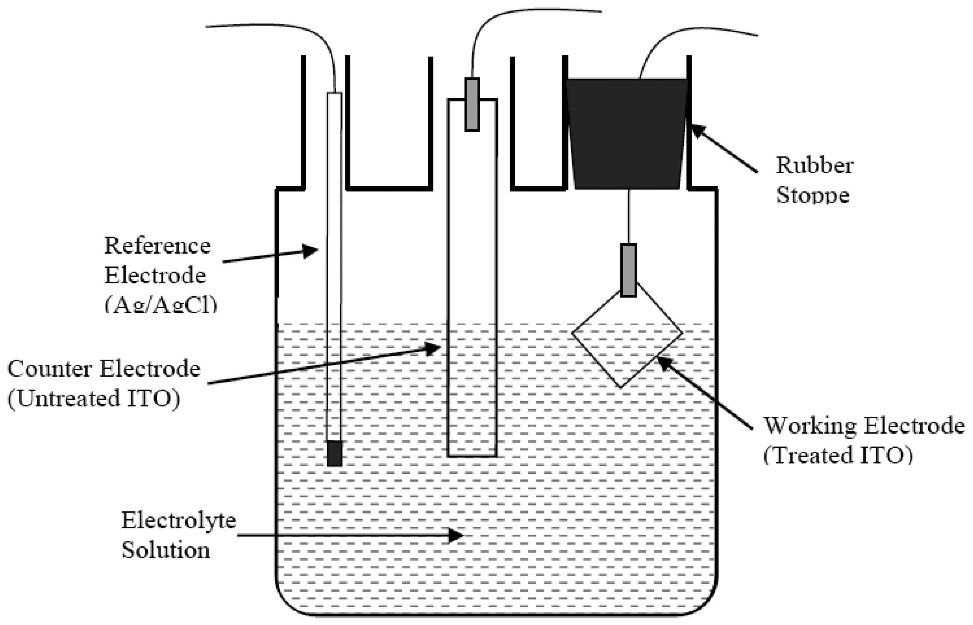
The electrochemical cell used in this research was shaped similar to a beaker with three openings all located on the top (Figure 1). The reference and counter electrodes were secured at the top through two openings. The working electrode was suspended in the electrolyte solution such that the maximum surface area of the working electrode was in contact with the electrochemical solution. The approximate surface area of the working electrode exposed to the solution in the cell was 1 cm2. The height of the working electrode relative to the cell was fixed by the rubber stopper. The volume of liquid used in this cell was 50 ml to cover the three electrodes.
2.4 Preparation of the Theophylline Imprinted Biomimetic Sensor
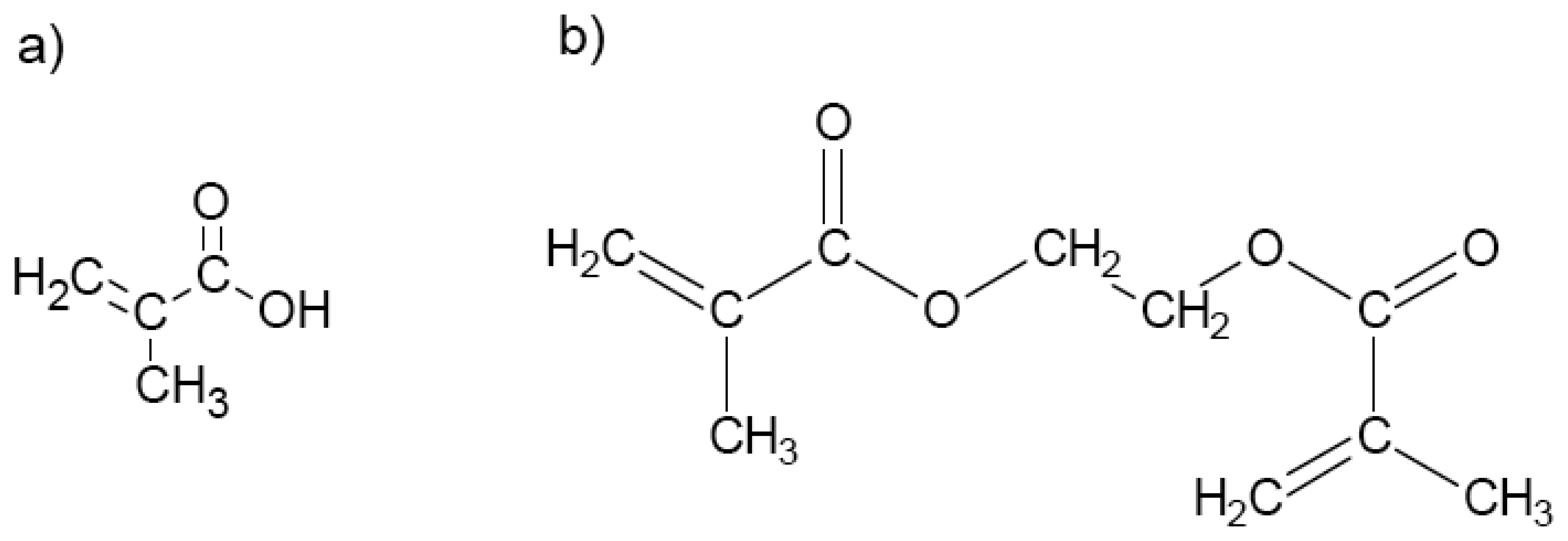
The process of preparing the ITO electrode and forming the theophylline MIP was similar to the procedure of Kindschy and Alocilja [8]. The ITO electrode was silanized in a 10% solution (v/v) of 3-MPS in toluene for 6 h at 80°C under nitrogen atmosphere. Silanization activated the surface of the electrode, which allowed the MIP to be covalently bonded to the surface. Following silanization, the electrode was rinsed with methanol and dried under nitrogen environment. The polymer was prepared using methacrylic acid (MAA) as the functional monomer and ethylene glycol dimethacrylate (EGDMA) as the cross-linker (Figure 2). The initiator was 2,2′-azobisisobutyronitrile (AIBN), the porogenic solvent was N,N-dimethylformamide (DMF), and theophylline was used as the template. Chemical inhibitors were removed from MAA and EGDMA by passing them through an inhibitor removal column (Aldrich 30,631-2) immediately before use. MAA (0.119 ml), EGDMA (1.20 ml), AIBN (0.036 g), and theophylline (0.063 g) were added to 3.31 ml of DMF. The silanized electrode was immersed in 2 ml of the above solution and placed under nitrogen atmosphere. The electrode was allowed to polymerize for 12 h at 60°C. After this preparation, the theophylline-imprinted polymer on ITO will be referred to hereafter as the biomimetic MIP-ITO sensor. A reference non-imprinted polymer (blank) to be referred to as B-ITO was similarly made by omitting the theophylline template.
2.5 Extraction of Template
Both the MIP-ITO and blank sensors were washed in a 9:1 v/v solution of methanol and acetic acid for 1 h. This washing removed the template and any excess polymer. The MIP and blank sensors were rinsed twice with methanol followed by rinsing twice with water and twice more with methanol. The MIP and blank sensors were stored in water until signal measurement to prevent drying or cracking of the polymer.
2.6 Baseline Measurement
The electrochemical cell used in this research had both sides of the sensor exposed through a dipping format with an approximate surface area of 1 cm2. Before addition of the theophylline analyte, a baseline was obtained for each sensor (MIP and blank) using a blank electrolyte that was an aqueous solution of 0.1 M potassium nitrate and 5 mM potassium ferrocyanide. A volume of 50 ml was added to the electrochemical cell. Cyclic voltammetry was performed with the blank solution using a Versastat II Potentiostat/Galvanostat (Princeton Applied Research, Oak Ridge, TN). The working electrode was the treated (imprinted) material, the reference electrode was the Ag/AgCl, and the counter electrode was the untreated ITO material. The potentiostat was run in the ramp, one vertex multi mode. The potential was cycled between –1 V to +1 V at a scan rate of 200 mV/s. The resulting current was measured and plotted against the potential. After measurement, the blank solution was discarded.
2.7 Rebinding and Measurement of Theophylline Analyte
The rebinding of the analyte was performed in the same electrochemical cell by cyclic voltammetry measurements. The analyte solution was the blank (0.1 M potassium nitrate and 5 mM potassium ferrocyanide) with the addition of the appropriate theophylline concentration. The analyte solution of 50 ml was added to the electrochemical cell and cyclic voltammetry was performed. The sensitivity of the MIP sensor was evaluated at four theophylline concentrations: 1, 2, 3, and 4 mM. Signal measurements were done according to Section 2.6.
2.8 Selectivity Evaluation
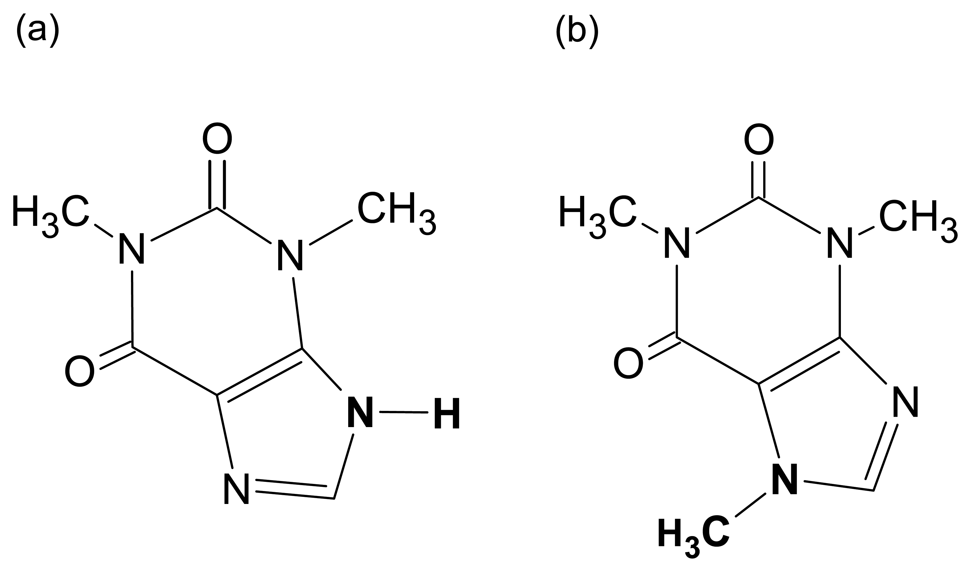
The selectivity of the MIP sensor was evaluated using caffeine, which is structurally related to the target analyte, theophylline. As shown in Figure 3, the structures of theophylline and caffeine differ primarily in the group attached to the nitrogen atom. In theophylline, this group is a single hydrogen atom while in caffeine this is a CH3 group. This slight structural difference makes caffeine ideal for testing the crossreactivity of the theophylline-imprinted polymer sensor. The selectivity testing was performed using four concentrations of caffeine: 1, 2, 3, and 4 mM.
2.9 Light Absorbance Measurements
The MIP and blank polymer were prepared according to Section 2.4. Following template removal for 1 h in 9:1 methanol/acetic acid, 50 mg of both the MIP and non-imprinted polymer was removed, weighed, and rebound with the analyte separately. The rebinding concentration of 5 mM theophylline was combined with each of the polymers and allowed to soak for 25 min. After rebinding, each polymer was immersed in fresh water for 20 s to remove weakly adhering analyte. Each polymer was combined with 1 ml of deionized water and placed in a 1 ml cuvette. The light absorbance of only the polymer (polymer without the ITO electrode) was measured between a wavelength of 200 nm to 800 nm with a SmartSpec 3000 Spectrophotometer from Bio-Rad (Hercules, CA).
2.10 Statistical Analysis
2.10.1 Determination of Peak currents on Cyclic Voltammograms
The maximum (ipc) and minimum (ipa) peak currents at the oxidation-reduction shifts on the cyclic voltammograms were selected for statistical analysis. The current ratio was the “peak current after addition of the analyte” to the “peak current before addition of the analyte” and was used to compare between cyclic voltammograms. All cyclic voltammograms were an average of three trials. Each trial was performed on a separate day using fresh solutions and new polymers to account for slight variations in the solutions and day-to-day error.
2.10.2 Evaluation of Blank and MIP Sensors
The equality of variances was tested on the absorbance values and current ratios using F-test prior to testing mean differences with t-test. T-test was performed on the absorbance values and mean current ratios to determine if the difference between the MIP and blank sensor was significant. The difference in the mean values was considered to be significant when the p-value was less than 0.05, representing a 95% confidence level.
2.11 Surface Characterization
The surface of the MIP sensor was evaluated using atomic force microscopy (AFM). AFM experiments were performed with a Dimension 3100 Scanning Probe Microscope (Veeco Instruments Inc., Woodbury, New York) with a NanoScope IIIa SPM Controller (Digital Instruments, Santa Barbara, California) with the tapping mode. AFM images were obtained after template removal before rebinding and after template removal and rebinding. The removal of the template was performed for 1 h in 9:1 methanol/acetic acid. The rebinding was performed for 25 min in a 5 mM aqueous solution of theophylline. After rebinding, the sensor was immersed in clean water for 20 s to remove weakly adhering analyte.
3 Results and Discussion
3.1 Theory of Detection
The rebinding of the analyte to the imprinted polymer was observed through electrochemical measurements. The redox couple Fe(CN)63-/4- used in this research undergoes reasonably fast kinetics of electron transfer and was selected for this reason [11]. The effect the rebinding of analyte to the MIP has upon this reversible reaction is monitored through measurement by cyclic voltammetry.
The current in the imprinted polymer is enhanced upon binding of the target analyte. Previous studies have shown an increase in current through potentiometric measurement [9,12,13]. The reason for the increase in current upon binding of the analyte to the imprinted polymer is hypothesized to be due to the increase in the permeability of the polymer, called the shrinking effect. When the analyte binds in the imprinted sites, the polymer shrinks around the analyte, thereby increasing the size of the surrounding pores in the polymer. The increase in the pore size increases the permeability of the polymer and allows the charge to flow less restricted [14]. The less restricted electron flow results in an increase in the measured current.
3.2 Confirmation of Imprinted Polymer
Theophylline at a concentration of 5 mM exhibited a maximum absorbance of 0.746 absorbance units (AU) at a wavelength of 295 nm. Since the maximum absorbance for theophylline occurred at 295 nm, the absorbance of the non-imprinted polymer and MIP at this wavelength was used for further analysis.
The light absorbance values for the non-imprinted polymer and MIP at a wavelength of 295 nm were 0.038 ± 0.025 AU for the blank and 0.203 ± 0.055 AU for the MIP with a P-value of 0.018. The absorbance measurements of the non-imprinted polymer compared to the MIP were significantly different at a 95% confidence level, indicating that an imprinted polymer was successfully formed for theophylline.
3.3 Characterization of Surface
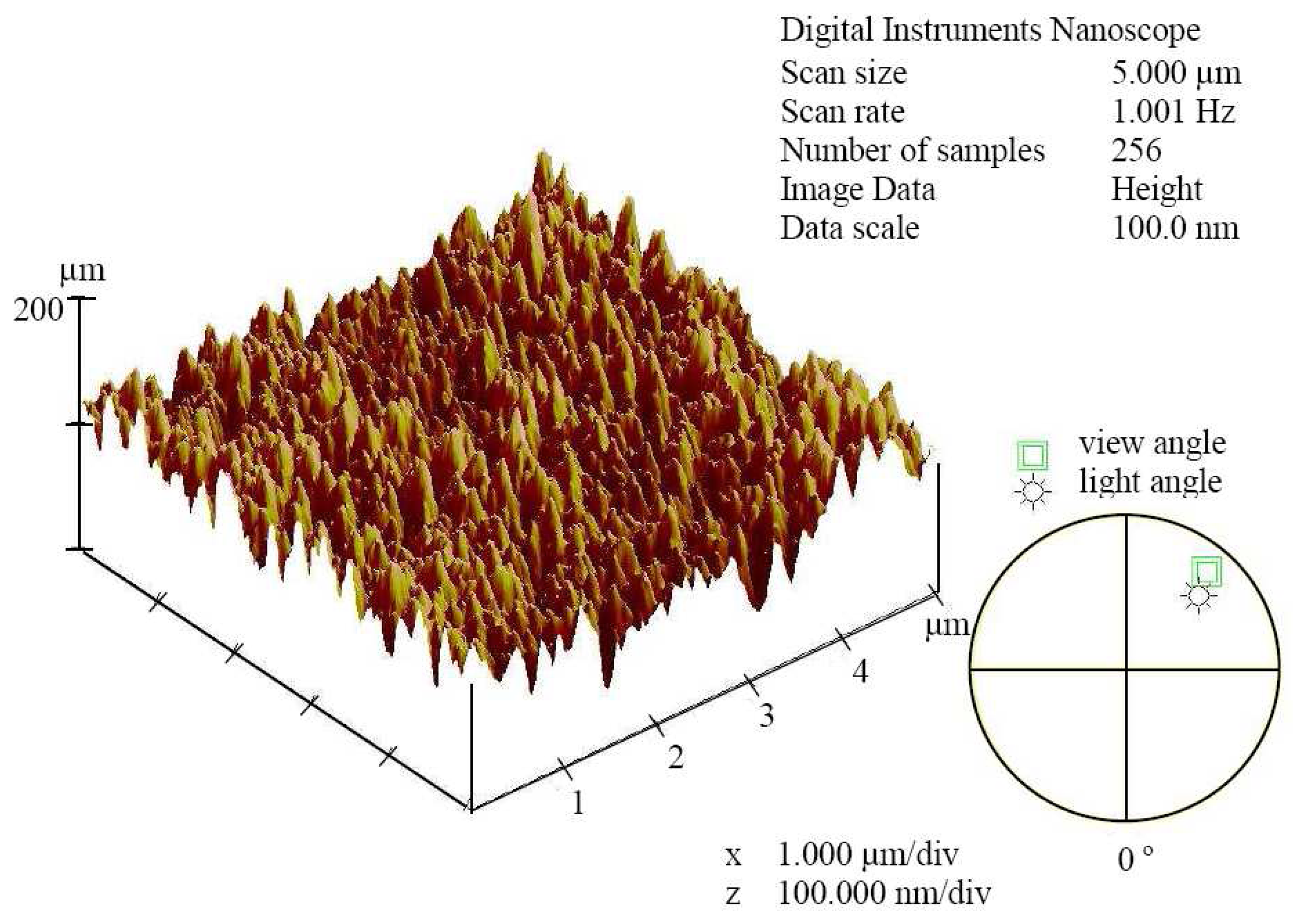
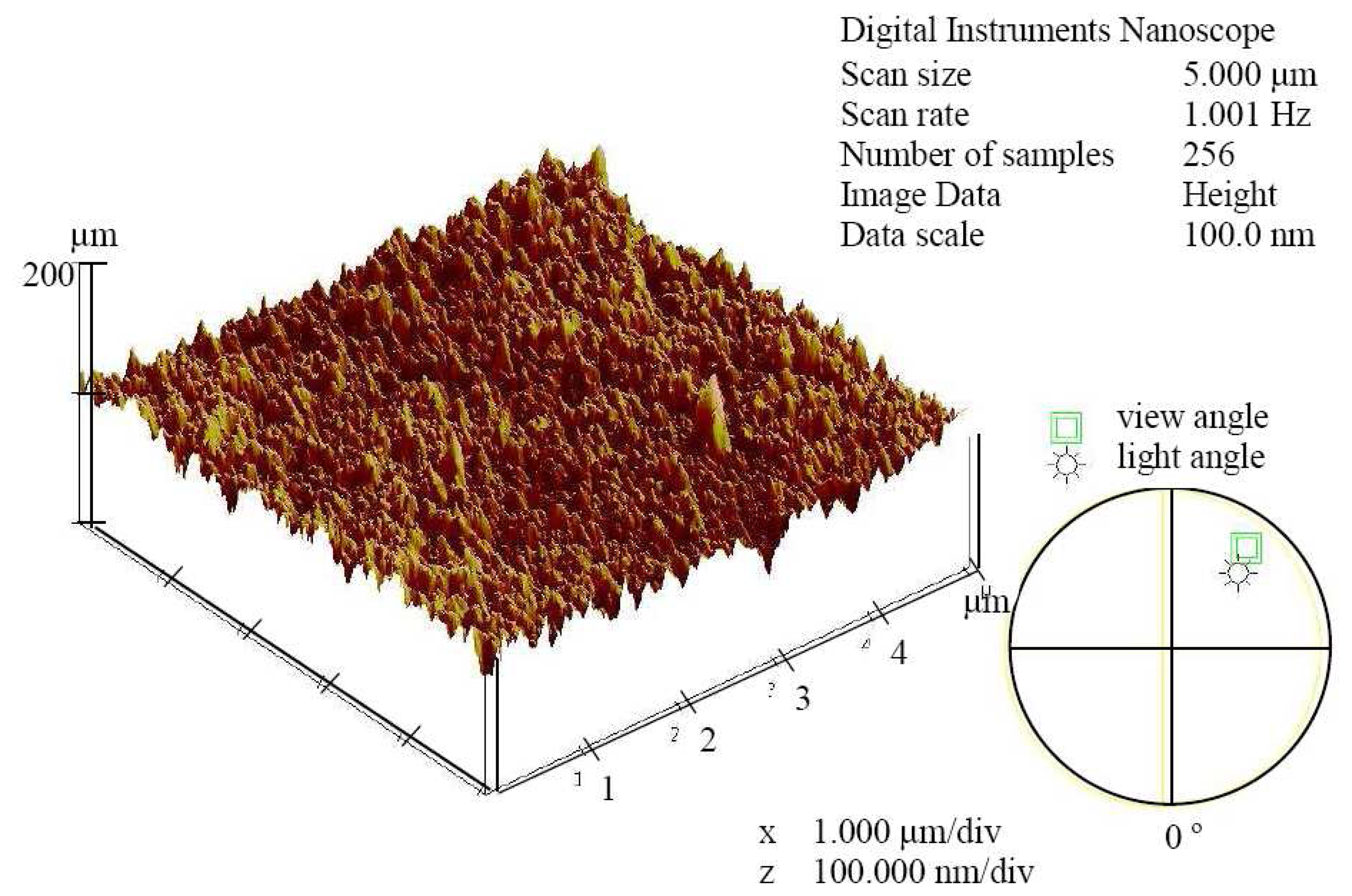
The surface of the MIP was evaluated after template removal and after rebinding. The AFM image after template removal is shown in Figure 4 and the image after rebinding is displayed in Figure 5.
The mean surface heights and standard deviations were 138.02 nm ± 17.735 nm for the MIP-ITO after extraction of the template and 95.522 nm ± 9.290 nm for the MIP-ITO after rebinding. The MIP-ITO after template extraction (Figure 4) is rougher than the MIP-ITO after rebinding (Figure 5). This can be observed visually from the images as well as by comparing the standard deviations of the heights. The standard deviation of the MIP-ITO after template extraction is almost two times greater than the standard deviation after rebinding. The decrease in the surface roughness upon analyte rebinding is hypothesized to be due to the shrinking effect. Upon rebinding of the target analyte, the polymer shrinks around the analyte, thereby reducing the mean surface height and roughness of the polymer.
3.4 Sensitivity and Selectivity Testing
3.4.1 Background Measurement
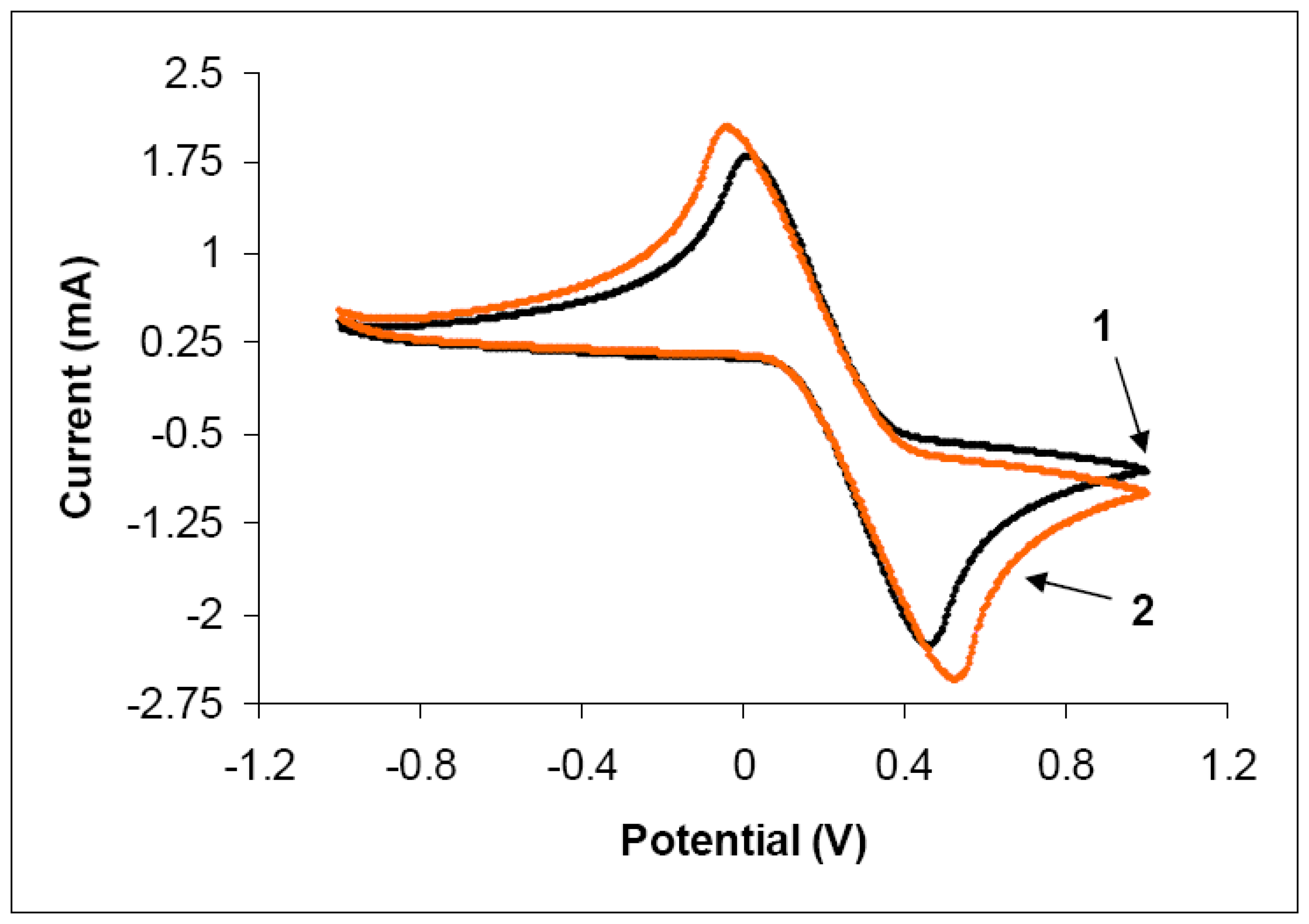
The cyclic voltammogram of the background measurement of 5 mM potassium ferrocyanide and 0.1 M potassium nitrate with 5 mM theophylline is shown in Figure 6. The working electrode was cleaned, untreated ITO (no silanization or polymer). The presence of theophylline does not alter the shape of the cyclic voltammogram compared to a typical voltammogram of potassium nitrate and potassium ferrocyanide.
3.4.2 Sensitivity of MIP-ITO Sensor
The sensitivity of the MIP-ITO sensor was evaluated by testing the response at 4 analyte concentrations: 1, 2, 3, and 4 mM. The response before addition of the analyte served as a baseline for evaluating the response of each sensor. For this reason, the response of each sensor to the analyte was compared to the baseline measurement. This allowed the sensors to be compared and evaluated, and accounted for any slight differences in conductivity that may have been present between samples.
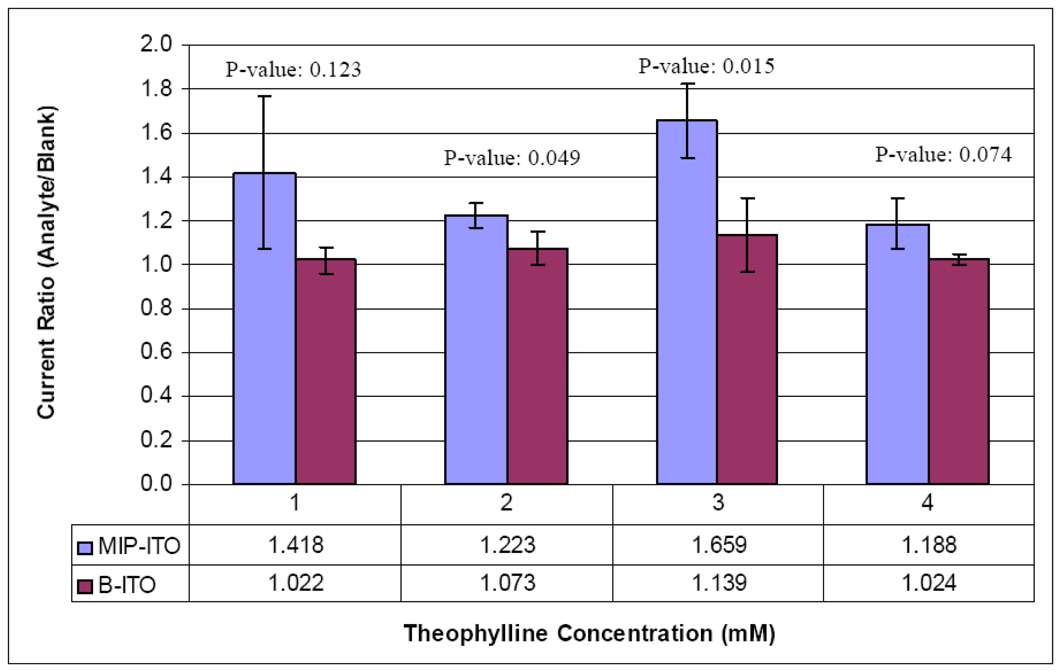
The ratio of the maximum and minimum peak currents for 1, 2, 3, and 4 mM theophylline are shown in Figures 7 and 8, respectively. The ratio refers to the peak current on the curve of the selected concentration (1, 2, 3, or 4 mM Thy) divided by the peak current on the baseline curve without theophylline (no Thy). The standard deviation of three samples is shown for both the MIP-ITO and B-ITO sensors at each concentration. The resulting P-values using t-test are also shown in the figures at each concentration.
The ratio of the maximum currents was compared for the B-ITO and the MIP-ITO sensors at each analyte concentration. The currents ratios (max or min) were not significantly different for the 1 mM theophylline concentration. The ratio of the maximum currents was significantly different (P<0.05) at a theophylline concentration of 2 mM, but not significant at the minimum current. When testing was performed with 3 mM theophylline, the ratio of the maximum currents was significantly different (P<0.05), and the ratio of the minimum currents tended to significance (P-value of 0.068). The ratio of maximum currents at a concentration of 4 mM tended to significance (P-value of 0.074). The MIP-ITO sensor could detect the theophylline analyte in the range of 2 to 4 mM. The optimum concentration of theophylline for detection was 3 mM, which resulted in the highest P-value between the B-ITO and MIP-ITO.
The maximum currents were used for evaluating the sensitivity of the MIP-ITO sensor. This was the region where the most current would flow based upon the increase in the permeability and highest number of free electrons that would be present. In this research, the current at a single potential was used to evaluate the success or failure of each sensor. Future researchers may consider other analysis techniques such as principal component analysis or some type of modeling method to determine what region of data on the cyclic voltammogram should be compared for improved examination of the results.
Theophylline is a small bronchodilator drug that is used in the treatment of asthma, bronchitis, emphysema, and other airways diseases. The amount needed in the blood to relieve airway constriction is between 5 to 15 μg/ml [15]. The sensitivity of the MIP-ITO sensor is between 2 to 4 mM theophylline, which is 360 to 900 μg/ml when converted into units used for the monitoring of theophylline. Further research will be necessary to increase the sensitivity of the biomimetic sensor to reach the 5 to 15 μg/ml range needed for delivery and monitoring in the medical industry.
The hook effect has been well established in immunoassay sensors [16,17] and states that at higher analyte concentrations, the over abundance of analyte may interfere rather than enhance the signal. The hook effect may be present in the MIP-ITO sensor and would account for the decline in sensitivity around the optimum concentration of analyte. At the optimum concentration, most of the analyte in the solution rebinds to the MIP surface. As the concentration of analyte increases past this concentration, the remaining analyte in the solution hinders the movement of the charge carriers in the electrolyte solution.
The maximum current yields a higher current and a better signal because as the redox reaction proceeds, more analyte binds to the surface of the MIP. As previously described, the permeability of the polymer is thought to increase as more analyte binds to the surface. The increased permeability results in more electron transfer, thus yielding a higher signal.
3.4.3 Selectivity of MIP-ITO Sensor
The selectivity of the sensor was tested using the structurally related molecule caffeine. The MIP-ITO sensor was tested at concentrations of 1, 2, 3, and 4 mM caffeine to determine the crossreactivity of the biomimetic sensor.
The MIP-ITO sensor and B-ITO did not show a noticeable response at any concentration of caffeine. The current ratios of the B-ITO and MIP-ITO at the maximum and minimum currents are shown in Tables 1 and 2, respectively. The mean current ratios and standard deviations are presented in the tables. The maximum current ratios of the B-ITO were compared to the MIP-ITO to determine the selectivity of the biomimetic sensor.
The differences in the mean currents ratios (maximum and minimum) for the B-ITO and MIP-ITO were not significant at a 95% confidence level when tested for selectivity. The P-values of the biomimetic sensor compared to the blank sensor were all greater than 0.05 when the sensor was tested with caffeine. The biomimetic sensor did not show any response to caffeine at the tested concentrations; therefore, the sensor was selective to the target analyte, theophylline.
5. Conclusions
This research demonstrated the successful formation of a molecularly imprinted polymer (MIP) and its attachment to an electrode. The formation of the MIP and its attachment to indium tin oxide (ITO) were monitored using AFM imaging. The MIP-ITO sensor was tested at four concentration levels with the target analyte, theophylline. The selectivity of the MIP-ITO sensor was determined using caffeine at the same concentrations. The sensitivity and selectivity of the MIP-ITO sensor was successfully evaluated at each concentration. The biomimetic sensor was able to detect the theophylline analyte in the range of 2 mM to 4 mM. The optimum analyte concentration for detection was 3 mM theophylline. The MIP-ITO sensor showed no cross reactivity to caffeine at concentrations of 2 mM to 4 mM and was therefore selective to theophylline. Further research could improve the sensitivity of the biomimetic sensor for theophylline allowing it to compete with current detection methods. Controlling the thickness of the polymer layer as well as investigating other measurement techniques may allow the detection range to reach 5 to 15 μg/ml needed by the medical industry. Once this sensitivity level is achieved, the stability and simplicity of the sensor will allow it to compete with other detection methods for theophylline.
References
- Haupt, K.; Mosbach, K. Plastic antibodies: developments and applications. Trends in Biotechnology 1998, 16, 468–475. [Google Scholar]
- Kindschy, L.M.; Alocilja, E.C. A Review of Molecularly Imprinted Polymers for Biosensor Development for Food and Agricultural Applications. Transactions of the ASAE 2004, 47, 1375–1382. [Google Scholar]
- Piletsky, S.A.; Turner, A.P.F. Electrochemical sensors based on molecularly imprinted polymers. Electroanalysis 2002, 14, 317–323. [Google Scholar]
- Ramström, O.; Skudar, K.; Haines, J.; Patel, P.; Brüggemann, O. Food analyses using molecularly imprinted polymers. Journal of Agricultural and Food Chemistry 2001, 49, 2105–2114. [Google Scholar]
- Takeuchi, T.; Haginaka, J. Separation and sensing based on molecular recognition using molecularly imprinted polymers. Journal of Chromatography B: Biomedical Sciences and Applications 1999, 728, 1–20. [Google Scholar]
- Hong, J.-M.; Anderson, P.E.; Qian, J.; Martin, C.R. Selectively-permeable ultrathin film composite membranes based on molecularly-imprinted polymer. Chem. Mater. 1998, 10, 1029–1033. [Google Scholar]
- Lai, E.P.C.; Fafara, A.; VanderNoot, V.A.; Kono, M.; Polsky, B. Surface plasmon resonance sensors using molecularly imprinted polymers for sorbent assay of theophylline, caffeine, and xanthine. Canadian Journal of Chemistry 1998, 76, 265–273. [Google Scholar]
- Kindschy, L.M.; Alocilja, E.C. A molecularly imprinted polymer on indium tin oxide and silicon. Biosensors and Bioelectronics 2005, 20, 2163–2167. [Google Scholar]
- Yoshimi, Y.; Ohdaira, R.; Iiyama, C.; Sakai, K. “Gate effect” of thin layer of molecularly-imprinted poly(methacrylic acid-co-ethyleneglycol dimethacrylate). Sensors and Actuators B: Chemical 2001, 73, 49–53. [Google Scholar]
- Sigma-Aldrich. Sigma Biochemicals & Reagents for LifeScience Research, 2004-2005 ed.; 2004; p. 1531. [Google Scholar]
- Pine Instrument Company Survey of three voltammetric methods.
- Blanco-López, M.C.; Lobo-Castañón, M.J.; Miranda-Ordieres, A.J.; Tuñón-Blanco, P. Voltammetric sensor for vanillylmandelic acid based on molecularly imprinted polymer-modified electrodes. Biosensors and Bioelectronics 2003, 18, 353–362. [Google Scholar]
- Blanco-López, M.C.; Lobo-Castañón, M.J.; Miranda-Ordieres, A.J.; Tuñón-Blanco, P. Voltammetric response of diclofenac-molecularly imprinted film modified carbon electrodes. Anal Bioanal Chem 2003, 377, 257–261. [Google Scholar]
- Piletsky, S.A.; Piletskaya, E.V.; Yano, K.; Kugimiya, A.; Elgersma, A.V. A biomimetic receptor system for sialic acid based on molecular imprinting. Analytical Letters 1996, 29, 157–170. [Google Scholar]
- National Jewish Medical and Research Center Theophylline: Questions and answers, 2005.
- Amarasiri Fernando, S.; Wilson, G.S. Studies of the ‘hook’ effect in the one-step sandwich immunoassay. Journal of Immunological Methods 1992, 151, 47–66. [Google Scholar]
- Rodbard, D.; Feldman, Y.; Jaffe, M.L.; Miles, L.E.M. Kinetics of two-site immunoradiometric (‘sandwich’) assays--II : Studies on the nature of the -high-dose hook effect. Molecular Immunology 1978, 15, 77–82. [Google Scholar]
Figure 1.
Three-electrode electrochemical cell with working electrode submerged.

Figure 2.
Chemical structures of (a) methacrylic acid and (b) ethylene glycol dimethacrylate [10].
Figure 2.
Chemical structures of (a) methacrylic acid and (b) ethylene glycol dimethacrylate [10].

Figure 3.
Chemical structures of (a) theophylline and (b) caffeine [10].
Figure 3.
Chemical structures of (a) theophylline and (b) caffeine [10].

Figure 4.
AFM image of MIP-ITO sensor after extraction of the theophylline template for 1 h in 9:1 methanol/acetic acid.
Figure 4.
AFM image of MIP-ITO sensor after extraction of the theophylline template for 1 h in 9:1 methanol/acetic acid.

Figure 5.
AFM image of MIP-ITO sensor after rebinding in 5 mM theophylline for 25 min.

Figure 6.
Cyclic voltammogram of 5 mM potassium ferrocyanide and 0.1 M potassium nitrate without theophylline (1) and with 5 mM theophylline (2) on untreated ITO.
Figure 6.
Cyclic voltammogram of 5 mM potassium ferrocyanide and 0.1 M potassium nitrate without theophylline (1) and with 5 mM theophylline (2) on untreated ITO.

Figure 7.
Comparison of the ratio of maximum currents of MIP-ITO sensor to B-ITO at various analyte concentrations.
Figure 7.
Comparison of the ratio of maximum currents of MIP-ITO sensor to B-ITO at various analyte concentrations.

Figure 8.
Comparison of the ratio of minimum currents of MIP-ITO sensor to B-ITO at various analyte concentrations.
Figure 8.
Comparison of the ratio of minimum currents of MIP-ITO sensor to B-ITO at various analyte concentrations.


Table 1.
Ratio of Maximum Currents of B-ITO and MIP-ITO Sensor at Various Counter Analyte Concentrations
| Counter-Analyte Concentration | B-ITO | MIP-ITO | P-Value |
|---|---|---|---|
| 1 mM Caf | 1.403 ± 0.350 | 1.130 ± 0.265 | 0.343 |
| 2 mM Caf | 1.172 ± 0.217 | 1.065 ± 0.236 | 0.595 |
| 3 mM Caf | 1.250 ± 0.452 | 1.473 ± 0.721 | 0.681 |
| 4 mM Caf | 1.169 ± 0.111 | 0.970 ± 0.092 | 0.075 |
Means ± standard deviations (n=3). Data was tested within a row (one concentration).
Table 2.
Ratio of Minimum Currents of B-ITO and MIP-ITO Sensor at Various Counter Analyte Concentrations
| Counter-Analyte Concentration | B-ITO | MIP-ITO | P-Value |
|---|---|---|---|
| 1 mM Caf | 1.516 ± 0.530 | 1.068 ± 0.134 | 0.229 |
| 2 mM Caf | 1.139 ± 0.190 | 1.028 ± 0.098 | 0.419 |
| 3 mM Caf | 1.525 ± 0.861 | 2.020 ± 1.62 | 0.672 |
| 4 mM Caf | 1.329 ± 0.502 | 1.025 ± 0.575 | 0.419 |
Means ± standard deviations (n=3). Data was tested within a row (one concentration).
© 2007 by MDPI ( http://www.mdpi.org). Reproduction is permitted for noncommercial purposes.
Share and Cite
MDPI and ACS Style
Kindschy, L.M.; Alocilja, E.C. Development of a Molecularly Imprinted Biomimetic Electrode. Sensors 2007, 7, 1630-1642. https://doi.org/10.3390/s7081630
AMA Style
Kindschy LM, Alocilja EC. Development of a Molecularly Imprinted Biomimetic Electrode. Sensors. 2007; 7(8):1630-1642. https://doi.org/10.3390/s7081630
Chicago/Turabian StyleKindschy, Lisa M., and Evangelyn C. Alocilja. 2007. "Development of a Molecularly Imprinted Biomimetic Electrode" Sensors 7, no. 8: 1630-1642. https://doi.org/10.3390/s7081630