
Co-Channel Compatibility Analysis of IMT Networks and Digital Terrestrial Television Broadcasting in the Frequency Range 470–694 MHz Based on Monte Carlo Simulation

Abstract
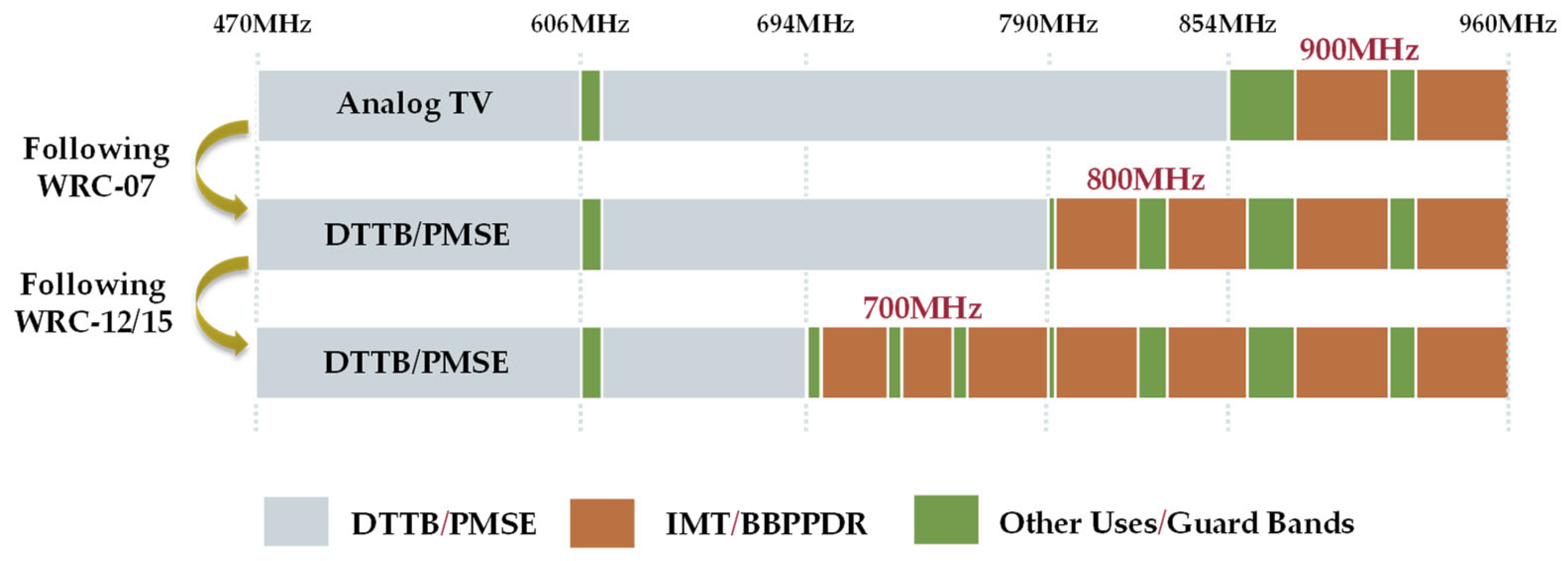
:1. Introduction
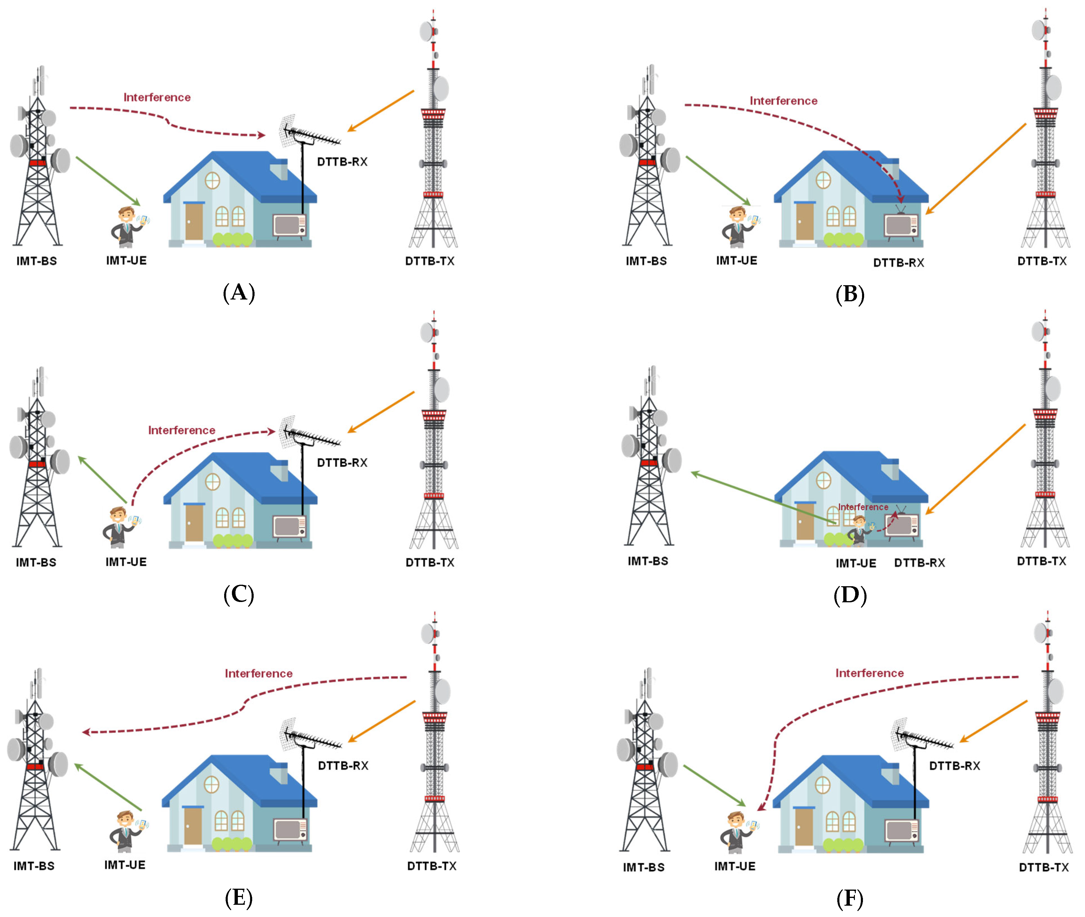
2. Coexistence Scenarios for DTTB and IMT
3. Technical Characteristics
3.1. IMT Parameters
3.2. DTTB Parameters
3.3. Propagation Models
3.4. Protection Criteria
- : Interference-to-noise ratio, dBm/MHz
- : Transmitter power density, dBm/MHz
- : Transmitter antenna gain, dBi
- : Receiver antenna gain, dBi
- : Propagation loss, dB
- : Other loss, like feeder loss or body loss, dB
- : Noise floor, dBm/MHz.
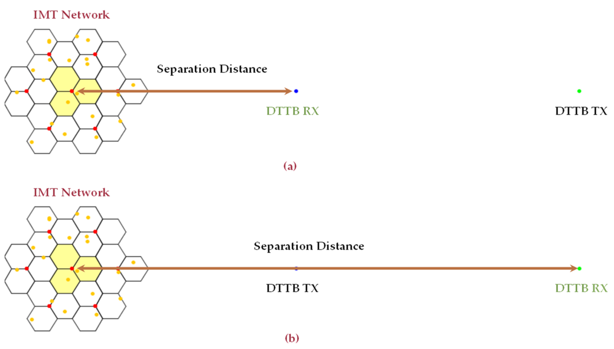
4. Methodology
4.1. Interferences from the IMT Systems to the DTTB
4.1.1. Scenario A
4.1.2. Scenario B
4.1.3. Scenario C
4.1.4. Scenario D
4.2. Interferences from the DTTB to the IMT Systems
4.2.1. Scenario E
4.2.2. Scenario F
5. Results and Compatibility Analysis
5.1. Interferences from the IMT Systems to the DTTB
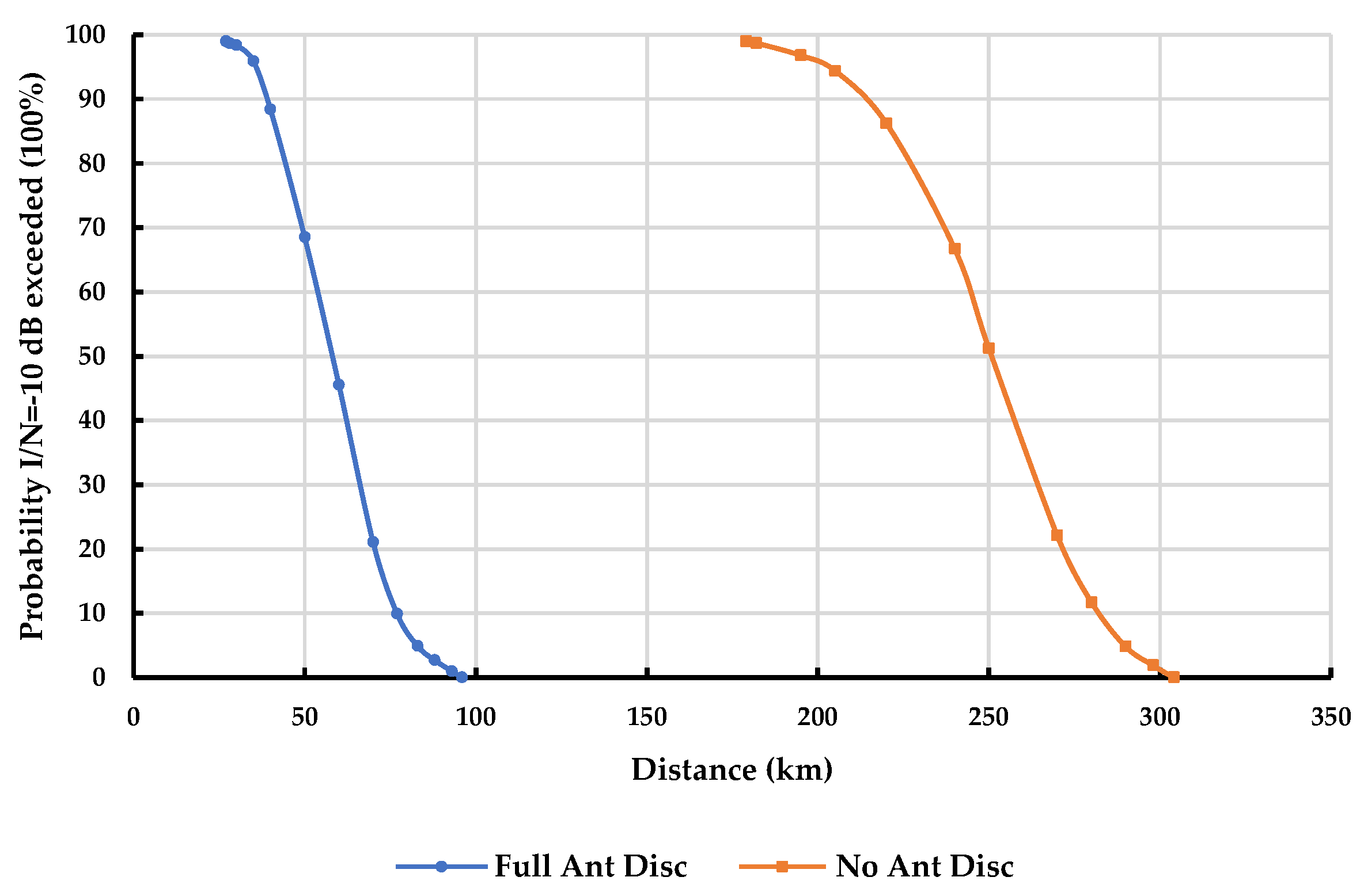
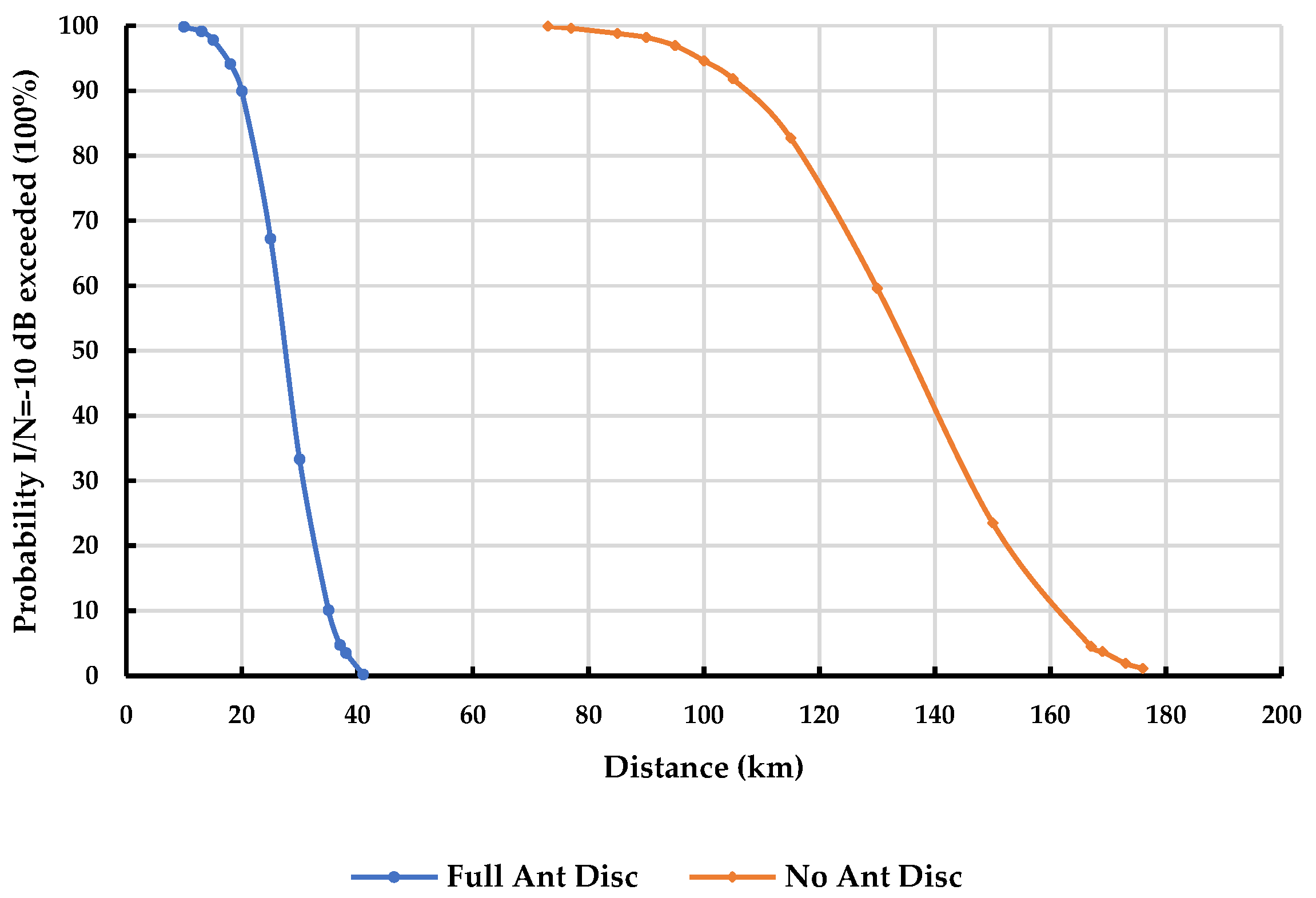
5.1.1. Scenario A
- Rural DTTB receiver: A separation distance of 83 km is required with full antenna discrimination, while a separation distance of 290 km is needed without antenna discrimination.
- Urban DTTB receiver: A separation distance of 37 km is necessary with full antenna discrimination, whereas a separation distance of 167 km is required without antenna discrimination.
5.1.2. Scenario B
5.1.3. Scenario C
5.1.4. Scenario D
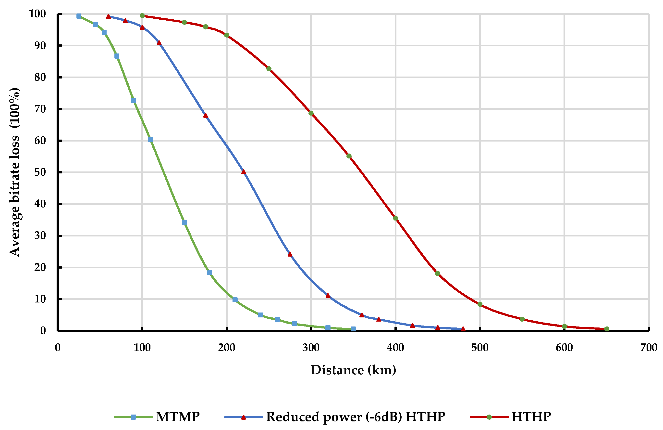
5.2. Interferences from the IMT Systems to the DTTB
5.2.1. Scenario E
5.2.2. Scenario F
6. Conclusions
- For fixed outdoor DTTB reception interfered with by IMT-BSs, it is observed that:
- For portable indoor DTTB reception interfered with by IMT-BSs, it is observed that:
- For fixed outdoor DTTB reception interfered with by IMT-UEs, it is observed that:
- For portable indoor DTTB reception interfered with by IMT-UEs, it is observed that:
- For IMT uplink reception interfered with by a DTTB transmitter, it is observed that:
- For IMT downlink reception interfered with by a DTTB transmitter, it is observed that:
Author Contributions
Funding
Institutional Review Board Statement
Informed Consent Statement
Data Availability Statement
Acknowledgments
Conflicts of Interest
References
- International Telecommunication Union (ITU), Geneva, Switzerland. Available online: https://www.itu.int/ (accessed on 6 February 2023).
- ITU. Final Acts of the Regional Radiocommunication Conference for Planning of the Digital Terrestrial Broadcasting Service in Parts of Regions 1 and 3, in the Frequency Bands 174–230 MHz and 470–862 MHz (RRC-06), Geneva, Switzerland, 15 May–16 June 2006. Available online: https://www.itu.int/pub/R-ACT-RRC.14-2006/en (accessed on 6 February 2023).
- ITU. The Final Acts of the World Radiocommunication Conference 2007 (WRC-07); ITU: Geneva, Switzerland, 2007; Available online: http://handle.itu.int/11.1002/pub/802313bd-en (accessed on 7 February 2023).
- ITU. The Final Acts of the World Radiocommunication Conference 2012 (WRC-12); ITU: Geneva, Switzerland, 2012; Available online: http://handle.itu.int/11.1002/pub/805627a4-en (accessed on 7 February 2023).
- ITU. The Final Acts of the World Radiocommunication Conference 2015 (WRC-15); ITU: Geneva, Switzerland, 2015; Available online: http://handle.itu.int/11.1002/pub/80d4e1c0-en (accessed on 7 February 2023).
- The European Parliament and the Council of the European Union. Decision (EU) 2017/899 of the European Parliament and of the Council of 17 May 2017 on the Use of the 470–790 MHz Frequency Band in the Union; The European Parliament and the Council of the European Union: Strasbourg, France, 2017; pp. 1–7. Available online: http://data.europa.eu/eli/dec/2017/899/oj (accessed on 16 February 2023).
- ITU. Agenda items and status of studies. In Proceedings of the World Radiocommunication Conference 2023 (WRC-23), Dubai, United Arab Emirates, 20 November–15 December 2023. Available online: https://www.itu.int/wrc-23/ (accessed on 6 March 2023).
- Taha, H.; Vári, P.; Nagy, S. Analysis of the WRC-23 Agenda Item Concerning the Future Use of the 470–694 MHz Band in Europe. Infocommun. J. 2023. accepted. [Google Scholar]
- Taha, H.; Vári, P.; Nagy, S. Survey on Coexistence of Terrestrial Television Systems and Mobile Fixed Communications Networks in Digital Dividend Bands. In Proceedings of the Technical University of Sofia (TU-Sofia); Technical University of Sofia: Sofia, Bulgaria, 2022; pp. 29–36. [Google Scholar] [CrossRef]
- Alghaihab, A.; Ragheb, A.M.; El Falou, A.; Khan, P.Z.; Alhawas, I.Y.; Almanea, M.M.; Maghrabi, A.; Aljanoobi, M.S.; Aljanoobi, M.S.; Alabdulqader, M.A.; et al. Sharing and Compatibility Studies for IMT and DTTB Systems in the Sub-700 MHz UHF Band. IEEE Access 2023, 11, 87626–87640. [Google Scholar] [CrossRef]
- Ancans, G.; Stankevicius, E.; Bobrovs, V.; Paulikas, S. Evaluation of LTE 700 and DVB-T electromagnetic compatibility in adjacent frequency bands. In Proceedings of the Electromagnetics Research Symposium Proceedings, Prague, Czech Republic, 6–9 July 2015; pp. 585–589. [Google Scholar]
- Ancans, G.; Stankevicius, E.; Bobrovs, V. Assessment of DVB-T compatibility with LTE in adjacent channels in 700 MHz band. Elektron. Ir Elektrotechnika 2015, 21, 69–72. [Google Scholar] [CrossRef]
- Ancans, G.; Stankevicius, E.; Bobrovs, V.; Ivanovs, G. Estimation of electromagnetic compatibility between DVB-T/DVB-T2 and 4G/5G in the 700 MHz band for co-channel case. Latv. J. Phys. Tech. Sci. 2020, 57, 30–38. [Google Scholar] [CrossRef]
- Więcek, D.; Niewiadomski, D.; Mora, M. Compatibility analysis of the 4G/5G systems with DTT in the 700 MHz frequency band. In Proceedings of the 2018 Baltic URSI Symposium (URSI), Poznań, Poland, 15–17 May 2018; pp. 261–264. [Google Scholar] [CrossRef]
- Okamoto, D.; Mello, L.; Almeida, M.; Rodriguez, C. Performance evaluation of digital TV and LTE systems operating in the 700 MHz band under the effect of mutual interference. J. Microw. Optoelectron. Electromagn. Appl. 2016, 15, 441–456. [Google Scholar] [CrossRef]
- Okamoto, D.; Mello, L.; Almeida, M. Analysis of the interference from LTE system in ISDB-TB Digital TV system at 700 MHz. In Proceedings of the SBMO/IEEE MTT-S International Microwave and Optoelectronics Conference (IMOC), Porto de Galinhas, Brazil, 3–6 November 2015; pp. 1–5. [Google Scholar] [CrossRef]
- Vita, A.; Milanesio, D.; Sacco, B.; Scotti, A. Assessment of interference to the DTT service generated by LTE signals on existing head amplifiers of collective distribution systems: A real case study. IEEE Trans. Broadcast. 2014, 60, 420–429. [Google Scholar] [CrossRef]
- Sanusi, O.; Gbenga-Ilori, A. LTE and Future DTV Compatibility Study in the UHF band in Nigeria. Int. J. Sci. Eng. Res. 2014, 5, 491–497. [Google Scholar]
- Bakare, B.; Idigo, V.; Nnebe, S. Interference Management for the Coexistence of DTTV and LTE Systems within the Proposed Digital Dividend Band in Nigeria. Eur. J. Electr. Eng. Comput. Sci. 2021, 5, 1–9. [Google Scholar] [CrossRef]
- Carciofi, C.; Garzia, A.; Lucidi, F.; Neri, A. Coexistence of DVB Television and 5G Services in Adjacent Bands. In Proceedings of the AEIT International Annual Conference (AEIT), Florence, Italy, 18–20 September 2019; pp. 1–6. [Google Scholar] [CrossRef]
- Mathe, D.; Farias, F.; Costa, J. Digital television interference on the LTE system in the 700 MHz band. In Proceedings of the XXXIII Simpósio Brasileiro de Telecomunicações (SBrT2015), Juiz de Fora, Brazil, 1–4 September 2015; p. 1e4. [Google Scholar] [CrossRef]
- Lysko, A.; Dludla, G. Considerations for coexistence: DVB-T2 broadcasting and LTE base stations in 700/800 MHz bands in South Africa. In Proceedings of the IEEE 4th Global Electromagnetic Compatibility Conference (GEMCCON), Stellenbosch, South Africa, 7–9 November 2018; pp. 1–6. [Google Scholar] [CrossRef]
- Laksana, G.; Linawati; Wiharta, D. Radio Frequency Band 700 MHz Utilization Plan for 5G Technology Implementation in Bali Province. In Proceedings of the 2021 IEEE Asia Pacific Conference on Wireless and Mobile (APWiMob), Bandung, Indonesia, 8–10 April 2021; pp. 167–172. [Google Scholar] [CrossRef]
- Aji, L. Field Measurement Test on Protection Ratio For DVB-T2 Interfered by TV White Space Devices. Syntax. Lit. J. Ilm. Indones. 2022, 7, 815–829. [Google Scholar] [CrossRef]
- Pastukh, A.; Tikhvinskiy, V.; Devyatkin, E.; Kulakayeva, A. Sharing Studies between 5G IoT Networks and Fixed Service in the 6425–7125 MHz Band with Monte Carlo Simulation Analysis. Sensors 2022, 22, 1587. [Google Scholar] [CrossRef]
- Pastukh, A.; Tikhvinskiy, V.; Devyatkin, E.; Kostin, A. Interference Analysis of 5G NR Base Stations to Fixed Satellite Service Bent-Pipe Transponders in the 6425–7125 MHz Frequency Band. Sensors 2023, 23, 172. [Google Scholar] [CrossRef]
- Fuentes, M.; Pardo, C.; Garro, E.; Barquero, D.; Cardona, N. Coexistence of digital terrestrial television and next generation cellular networks in the 700 MHz band. IEEE Wirel. Commun. 2014, 21, 63–69. [Google Scholar] [CrossRef]
- Ramírez, J.; Martínez, G.; Barquero, D.; Cardona, N. Interference analysis between digital terrestrial television (DTT) and 4G LTE mobile networks in the digital dividend bands. IEEE Trans. Broadcast. 2015, 62, 24–34. [Google Scholar] [CrossRef]
- Polak, L.; Milos, J.; Kresta, D.; Kratochvil, T.; Marsalek, R. LTE and DVB-T2 networks in the first digital dividend band in Europe: A coexistence study. In Proceedings of the 28th International Conference Radioelektronika, Prague, Czech Republic, 19–20 April 2018; pp. 1–4. [Google Scholar] [CrossRef]
- Borrego, J.; Gómez-García, R.; Carvalho, N.; Sanchez-Soriano, M.; Vieira, J. Coexistence without interference: Interference mitigation on DVB-T reception caused by neutral systems operating in the digital dividend band. IEEE Microw. Mag. 2018, 19, 29–43. [Google Scholar] [CrossRef]
- Chuma, E.; Lano, Y.; Cardoso, P.; Loschi, H.; Pajuelo, D. Design of stepped impedance microstrip lowpass filter for coexistence of TV broadcasting and LTE mobile system close to 700 MHz. SET Int. J. Broadcast Eng. 2018, 4, 53–57. [Google Scholar] [CrossRef]
- Fernández, O.; Fernández, T.; Gómez, Á. Compact Low-Cost Filter for 5G Interference Reduction in UHF Broadcasting Band. Electron. J. 2021, 10, 974. [Google Scholar] [CrossRef]
- Ferrante, M.; Fusco, G.; Restuccia, E.; Celidonio, M.; Masullo, P.; Pulcini, L. Experimental results on the coexistence of TV broadcasting service with LTE mobile systems in the 800 MHz band. In Proceedings of the Euro Med Telco Conference (EMTC), Naples, Italy, 12–15 November 2014; pp. 1–6. [Google Scholar] [CrossRef]
- Polak, L.; Kresta, D.; Milos, J.; Kratochvil, T.; Marsalek, R. Coexistence of DVB-T2 and LTE in the 800 MHz band: Analysis of DVB-T2 System Configurations. In Proceedings of the IEEE International Symposium on Broadband Multimedia Systems and Broadcasting (BMSB), Valencia, Spain, 6–8 June 2018; pp. 1–5. [Google Scholar] [CrossRef]
- Kalliovaara, J.; Ekman, R.; Jokela, T.; Arajärvi, A.; Gylen, H.; Paavola, J. 700 MHz Band LTE Uplink Interference to DTT Reception System Cabling. In Proceedings of the IEEE International Symposium on Broadband Multimedia Systems and Broadcasting (BMSB), Valencia, Spain, 6–8 June 2018; pp. 1–5. [Google Scholar] [CrossRef]
- Martínez-Pinzón, G.; Cardona, N.; Garcia-Pardo, C.; Fornés-Leal, A.; Ribadeneira-Ramírez, J. Spectrum Sharing for LTE-A and DTT: Field Trials of an Indoor LTE-A Femtocell in DVB-T2 Service Area. IEEE Trans. Broadcast. 2016, 62, 552–561. [Google Scholar] [CrossRef]
- Pupo, E.; Alvarez, R.; García, A.; Hernández, R. Protection ratios and overload thresholds between 700 mhz fdd-lte and analog/digital terrestrial television. 2020 IEEE International Symposium on Broadband Multimedia Systems and Broadcasting (BMSB), Paris, France, 27–29 October 2020; pp. 1–5. [Google Scholar] [CrossRef]
- Kalliovaara, J.; Ekman, R.; Talmola, P.; Höyhtyä, M.; Jokela, T.; Poikonen, J.; Paavola, J.; Jakobsson, M. Coexistence of DTT and Mobile Broadband: A Survey and Guidelines for Field Measurements. Wirel. Commun. Mob. Comput. 2017, 2017, 1563132. [Google Scholar] [CrossRef]
- Odiaga, M.; Joussef, H.; Medina, Y.; Augusto, M. Interference between UHF analog/digital television and LTE APT 700 MHz band: A field evaluation. In Proceedings of the 8th IEEE Latin-American Conference on Communications (LATINCOM), Medellin, Colombia, 15–17 November 2016; pp. 1–5. [Google Scholar] [CrossRef]
- Fadda, M.; Murroni, M.; Popescu, V. An Unlicensed Indoor HDTV Multi-Vision System in the DTT Bands. IEEE Trans. Broadcast. 2012, 58, 338–346. [Google Scholar] [CrossRef]
- Li, J.; Dang, S.; Wen, M.; Li, Q.; Chen, Y.; Huang, Y.; Shang, W. Index Modulation Multiple Access for 6G Communications: Principles, Applications, and Challenges. IEEE Netw. 2023, 37, 52–60. [Google Scholar] [CrossRef]
- Dang, S.; Di Renzo, M.; Wen, M.; Chafii, M.; Ko, Y.; Uchôa-Filho, B.; Younis, A. Editorial: Index Modulation for 6G Communications. Front. Comms. Net 2021, 2, 794311. [Google Scholar] [CrossRef]
- Wen, M.; Zheng, B.; Kim, K.; Renzo, M.; Tsiftsis, T.; Chen, K.; Al-Dhahir, N. A Survey on Spatial Modulation in Emerging Wireless Systems: Research Progresses and Applications. IEEE J. Sel. Areas Commun. 2019, 37, 1949–1972. [Google Scholar] [CrossRef]
- ITU. ITU-R TG6.1, Contribution 28. In Reply Liaison Statement from Working Party 5D to Task Group 6/1 (Copy to Working Parties 3K, 3M, 5A, 5B, 5C, 6A, 7D)—Preparations for WRC-23 Agenda Item 1.5—Information for Sharing and Compatibility Studies; ITU: Geneva, Switzerland, 2021; Available online: https://www.itu.int/md/R19-TG6.1-C-0028/en (accessed on 12 January 2023).
- ITU. Report ITU-R BT.2383-4. In Typical Frequency Sharing Characteristics for Digital Terrestrial Television Broadcasting Systems in the Frequency Band 470–862 MHz; ITU: Geneva, Switzerland, 2022; Available online: https://www.itu.int/pub/R-REP-BT.2383-4-2022 (accessed on 20 January 2023).
- ITU. ITU-R TG6.1, Contribution 32. In Liaison Statement from Working Party 6A to Task Group 6/1 (Copy to Working Parties 3K, 3M, 5A, 5B, 5C, 5D, and 7C)—Information Regarding the Broadcasting Service in the Band 470–960 MHz in Region 1; ITU: Geneva, Switzerland, 2021; Available online: https://www.itu.int/md/R19-TG6.1-C-0032/en (accessed on 12 January 2023).
- ITU. Recommendation ITU-R P.1546-6. In Method for Point-to-Area Predictions for Terrestrial Services in the Frequency Range 30 MHz to 4000 MHz; ITU: Geneva, Switzerland, 2019; Available online: https://www.itu.int/rec/R-REC-P.1546-6-201908-I/en (accessed on 20 January 2023).
- ITU. Recommendation ITU-R P.2109-1. In Prediction of Building Entry Loss; ITU: Geneva, Switzerland, 2023; Available online: https://www.itu.int/rec/R-REC-P.2109/en (accessed on 21 January 2023).
- ITU. Recommendation ITU-R BT.1895. In Protection Criteria for Terrestrial Broadcasting Systems; ITU: Geneva, Switzerland, 2011; Available online: https://www.itu.int/rec/R-REC-BT.1895-0-201105-I/en (accessed on 23 January 2023).
- ITU. Report ITU-R M.2292-0. In Characteristics of Terrestrial IMT-Advanced Systems for Frequency Sharing/Interference Analyses; ITU: Geneva, Switzerland, 2014; Available online: https://www.itu.int/pub/R-REP-M.2292-2014 (accessed on 14 March 2023).
- ITU. Recommendation ITU-R M.2101-0. In Modelling and Simulation of IMT Networks and Systems for Use in Sharing and Compatibility Studies; ITU: Geneva, Switzerland, 2017; Available online: https://www.itu.int/rec/R-REC-M.2101-0-201702-I/en (accessed on 14 March 2023).
- 3GPP TS 36.104. LTE; Evolved Universal Terrestrial Radio Access (E-UTRA); Base Station (BS) Radio Transmission and Reception (3GPP TS 36.104 Version 14.11.0 Release 14). Version 14.11.0, Release 14, France, 2022. Available online: https://www.etsi.org/deliver/etsi_ts/136100_136199/136104/14.11.00_60/ts_136104v141100p.pdf (accessed on 25 March 2023).
- ITU. Report ITU-R SM.2028-2. In Monte Carlo Simulation Methodology for the Use in Sharing and Compatibility Studies between Different Radio Services or Systems; ITU: Geneva, Switzerland, 2017; Available online: https://www.itu.int/pub/R-REP-SM.2028-2-2017 (accessed on 11 April 2023).
- ITU. ITU-R TG6.1, Contribution 31. In Reply Liaison Statement to Task Group 6/1 (Copied for Information to Working Parties 5A, 5B, 5C, 5D and 6A)—Issues Related to Propagation for Sharing Studies in Task Group 6/1; ITU: Geneva, Switzerland, 2021; Available online: https://www.itu.int/md/R19-TG6.1-C-0031/en (accessed on 12 January 2023).


| Approach | Purpose | Advantages | Limitations |
|---|---|---|---|
| Link budget analysis | Calculate the power budget for DTTB and IMT systems. |
|
|
| Simulations | Predict how DTTB and IMT systems interact in different scenarios. |
|
|
| Laboratory measurements | Controlled testing under controlled conditions. |
|
|
| Field measurements | Collect real-world data. |
|
|
| Base Station Characteristics Cell Structure | Urban Macro | Rural Macro |
|---|---|---|
| Cell radius | 0.5–5 km (typical value to be used in sharing studies for urban macro 1.5 km) | >5 km (typical value to be used in sharing studies 8 km) |
| Antenna height | 30 m, 20 m | |
| Sectorization | 3 sectors | |
| Antenna downtilt | Range from 0 to −7 degrees (typical value to be used in sharing studies −3 degrees) | |
| Frequency reuse | 1 | |
| Configuration of interfering sources | 7 tri-sectorized base stations | |
| Antenna pattern | Rec. ITU-R F.1336 (Rec. 3.1) ka = 0.7 kp = 0.7 kh = 0.7 kv = 0.3 Horizontal 3 dB beam width: 65° Vertical 3 dB beam width: determined from horizontal beam width (Rec. ITU-R F.1336) or actual antenna data. | |
| Tx Antenna orientation | Sector pointing direction based on 3GPP Tri-sector deployment | |
| Antenna polarization | Linear/±45° | |
| Feeder loss | 3 dB | |
| Typical channel bandwidth | 10 MHz | |
| Maximum BS output power (Report ITU-R M.2292) | 46 dBm in 10 MHz | |
| Maximum BS antenna gain (Report ITU-R M.2292) | 15 dBi | |
| Maximum BS output power/sector (EIRP) | 58 dBm baseline value/44.3 dBm results from Gaussian distribution used to simulate the IMT-BS power variation in time. | |
| Network loading factor | 20%, 50% | |
| TDD/FDD/SDL | FDD/SDL | |
| User Terminal Characteristics | Urban Macro | Rural Macro |
|---|---|---|
| Indoor UE usage (Report ITU-R M.2292) | 70% | 50% |
| Indoor UE penetration loss | Recommendation ITU-R P.2109 | |
| UE density for simultaneous transmission | 3 UEs/sector | |
| UE height | 1.5 m | |
| Avg UE output power | Transmit power control (TPC) utilization | |
| Typical UE antenna gain | −3 dBi | |
| Body loss | 4 dB | |
| Power control model | Rec. ITU-R M.2101 | |
| Maximum UE output power | 23 dBm | |
| Power target per RB | −92.2 dBm | |
| Path loss compensation factor | 0.8 dB | |
| DTTB Characteristics | ||||
|---|---|---|---|---|
| Centre frequency | 600 MHz | |||
| Channel BW | 8 MHz | |||
| Feeder loss | 4 dB | |||
| Noise figure | 6 dB | |||
| Cell edge coverage probability | 95% | |||
| DTTB Transmitter Characteristics | ||||
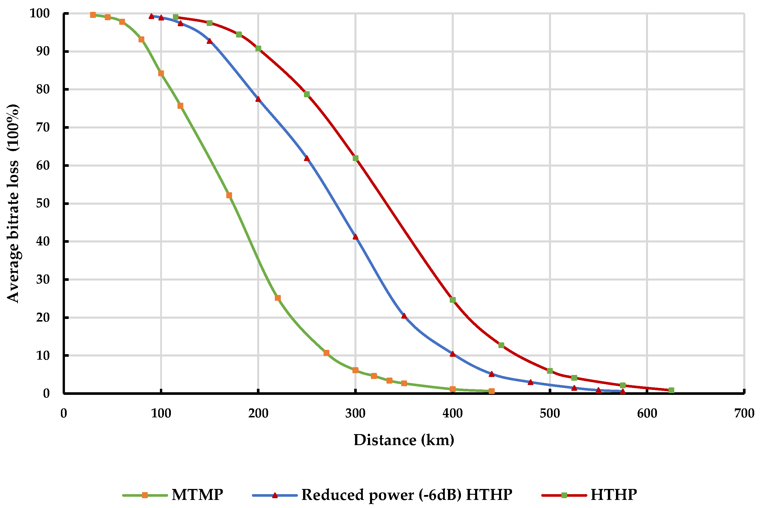
| Classes of DTTB Tx | HTHP | Reduced Power (−6dB) HTHP | MTMP | |
| ERP/e.i.r.p. | 83/85.15 dBm | 77/79.15 dBm | 67/69.15 dBm | |
| Coverage radius | 74.8 km | 74.8 km | 38 km | |
| Effective antenna height | 300 m | 300 m | 150 m | |
| Antenna height above ground level (a.g.l.) | 200 m | 200 m | 75 m | |
| Tx antenna | 10 dBi | 10 dBi | 10 dBi | |
| Antenna pattern—horizontal | Omnidirectional | Omnidirectional | Omnidirectional | |
| Antenna pattern—vertical antenna aperture | Using a 24λ aperture with 1° beam tilt | Using a 24λ aperture with 1° beam tilt | Using a 16λ aperture with a 1.6° beam tilt | |
| DTTB Receiver Characteristics | ||||
| DTTB reception modes | Fixed Outdoor Reception | Portable Indoor Reception | ||
| Receiver antenna height | 10 m | 1.5 m | ||
| Receiver antenna gain | −6.85 dBi (Full Discrimination) Report ITU-R BT.2383 (Results of 9.15–16 dBi) | 2.15 dBi | ||
| 9.15 dBi (No Discrimination) | ||||
| Building entry loss | - | 10 dB (Rural) | ||
| 18.14 dB (Urban) | ||||
| X-Pol. discrimination | −3 dB (Only applicable in no discrimination case) | |||
| Rx antenna pattern | ITU-R BT.419.13 | |||
| DTTB receiver location | At the DTTB coverage edge | |||
| Placement | 100 m × 100 m at cell edge | |||
| Antenna Discrimination | Load Factor | Minimum Coordination Distance (km) at X% of Time | |||
|---|---|---|---|---|---|
| 1.75% | 5% | 10% | 50% | ||
| Full Ant. Disc. | 50% | 83 | 75 | 70 | 63 |
| 20% | 73 | 66 | 62 | 58 | |
| No Ant. Disc. | 50% | 290 | 255 | 231 | 173 |
| 20% | 266 | 234 | 212 | 157 | |
| Antenna Discrimination | Load Factor | Minimum Coordination Distance (km) at X% of Time | |||
|---|---|---|---|---|---|
| 1.75% | 5% | 10% | 50% | ||
| Full Ant. Disc. | 50% | 37 | 34 | 31 | 29 |
| 20% | 33 | 30 | 28 | 26 | |
| No Ant. Disc. | 50% | 167 | 145 | 131 | 93 |
| 20% | 146 | 126 | 115 | 84 | |
| Rural area Full Ant. Dis. LF 50% | IMT BS power = 58 dBm | Classes of DTTB Transmitters | Time 1.75% | ||
| IP% | Active TV Users (%) | Separation Distance (km) | |||
| MTMP | 4.9% | 95.1% | 83 | ||
| Reduced power (−6 dB) HTHP | 4.7% | 95.3% | 83 | ||
| HTHP | 4.8% | 95.2% | 83 | ||
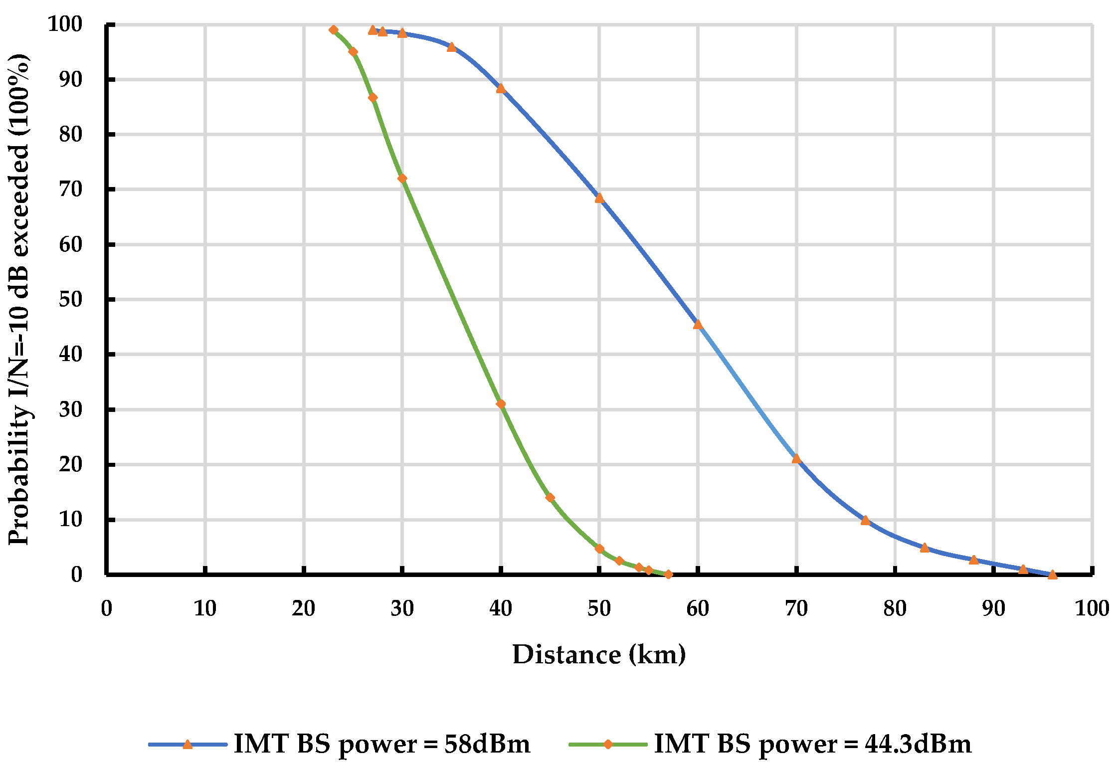
| Rural area Full Ant. Dis. LF 50% | MTMP DTTB | IMT BS Power | Minimum Coordination Distance (km) at X% of Time | |
| 1.75% | 50% | |||
| 58 dBm | 83 | 63 | ||
| 44.3 dBm | 50 | 45 | ||
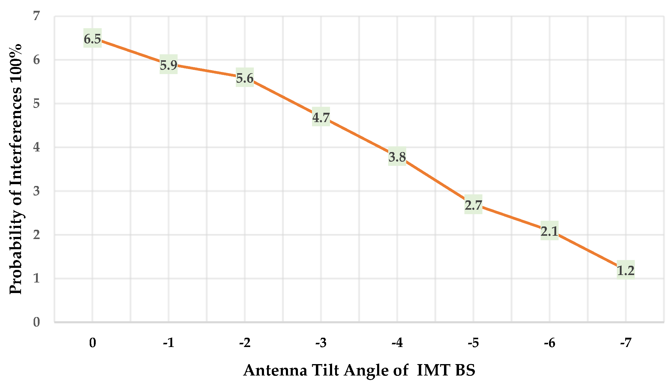
| Rural area Full Ant. Dis. LF 50% Time 1.75% | MTMP DTTB | Antenna Tilt Angle in IMT BS | IP% for Separation Distance = 83 km |
| 0 | 6.5% | ||
| −1 | 5.9% | ||
| −2 | 5.6% | ||
| −3 | 4.7% | ||
| −4 | 3.8% | ||
| −5 | 2.7% | ||
| −6 | 2.1% | ||
| −7 | 1.2% |
| Load Factor | Minimum Coordination Distance (km) at X% of Time | |||
|---|---|---|---|---|
| 1.75% | 5% | 10% | 50% | |
| 50% | 48 | 46 | 45 | 43 |
| 20% | 43 | 42 | 40 | 39 |
| Load Factor | Minimum Coordination Distance (km) at X% of Time | |||
|---|---|---|---|---|
| 1.75% | 5% | 10% | 50% | |
| 50% | 19 | 18 | 17 | 16 |
| 20% | 17 | 16 | 15 | 14 |
| Antenna Discrimination | Load Factor | Minimum Coordination Distance (km) at X% of Time | |
|---|---|---|---|
| 1% | 50% | ||
| Full Ant. Disc. | 50% | Coverage edge | Coverage edge |
| No Ant. Disc. | 50% | Coverage edge | Coverage edge |
| Classes of DTTB Transmitters | Minimum Coordination Distance (km) at X% of Time | |||
|---|---|---|---|---|
| 1% | 5% | 10% | 50% | |
| MTMP | 319 | 255 | 230 | 177 |
| Reduced power HTHP | >400 | 375 | 339 | 273 |
| HTHP | >500 | 437 | 405 | 320 |
| Classes of DTTB Transmitters | Minimum Coordination Distance (km) at X% of Time | |||
|---|---|---|---|---|
| 1% | 5% | 10% | 50% | |
| MTMP | 240 | 197 | 179 | 135 |
| Reduced power HTHP | 360 | 303 | 273 | 213 |
| HTHP | >450 | 359 | 325 | 256 |
| MTMP DTTB | Base Station Height | Minimum Coordination Distance (km) at X% of Time | |
| 1% | 50% | ||
| 30 m | 319 | 177 | |
| 20 m | 284 | 156 | |
| 15 m | 255 | 139 | |
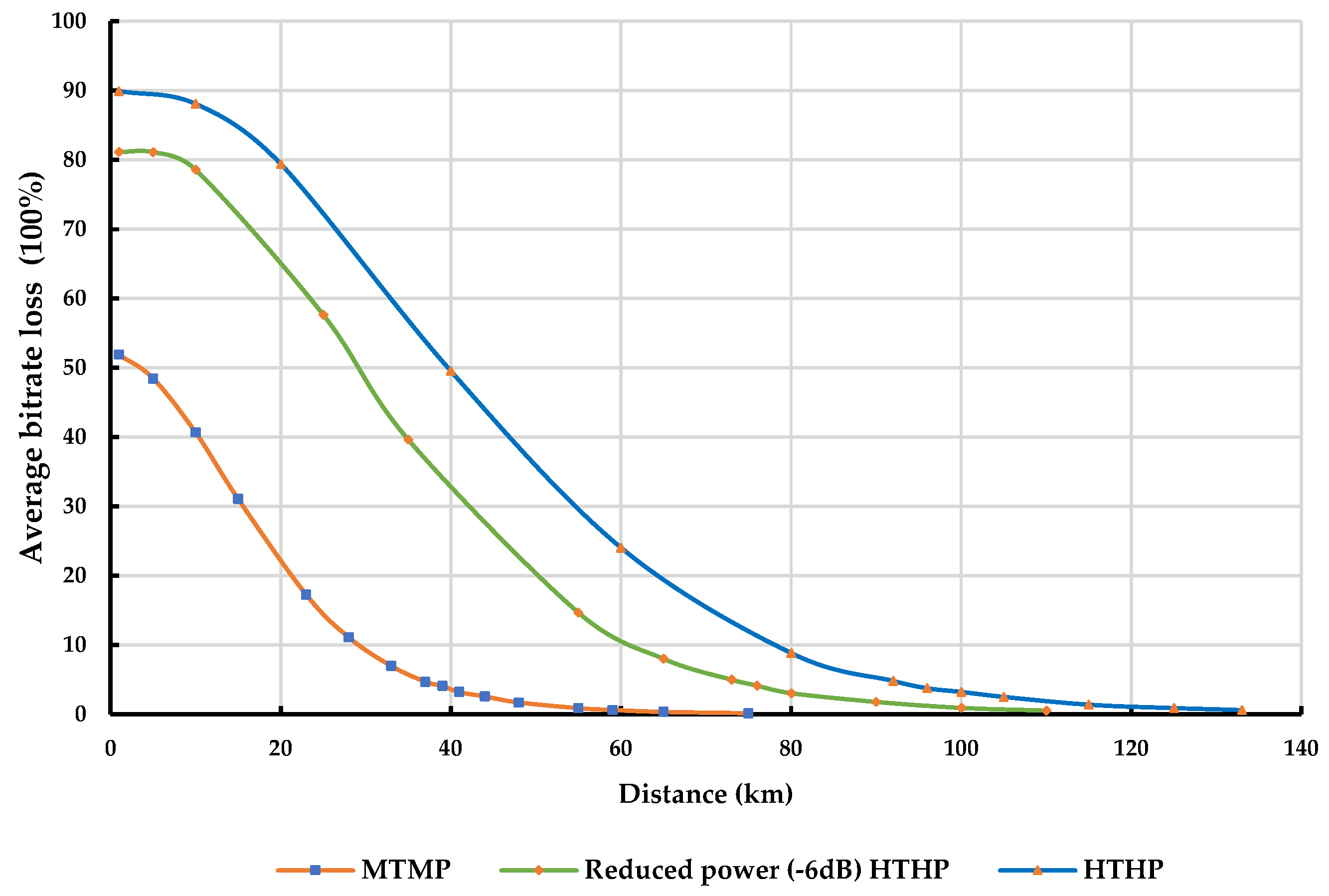
| Classes of DTTB Transmitters | Minimum Coordination Distance (km) at X% of Time | |||
|---|---|---|---|---|
| 1% | 5% | 10% | 50% | |
| MTMP | 37 | 36 | 36 | 36 |
| Reduced power HTHP | 73 | 67 | 64 | 63 |
| HTHP | 92 | 81 | 77 | 74 |
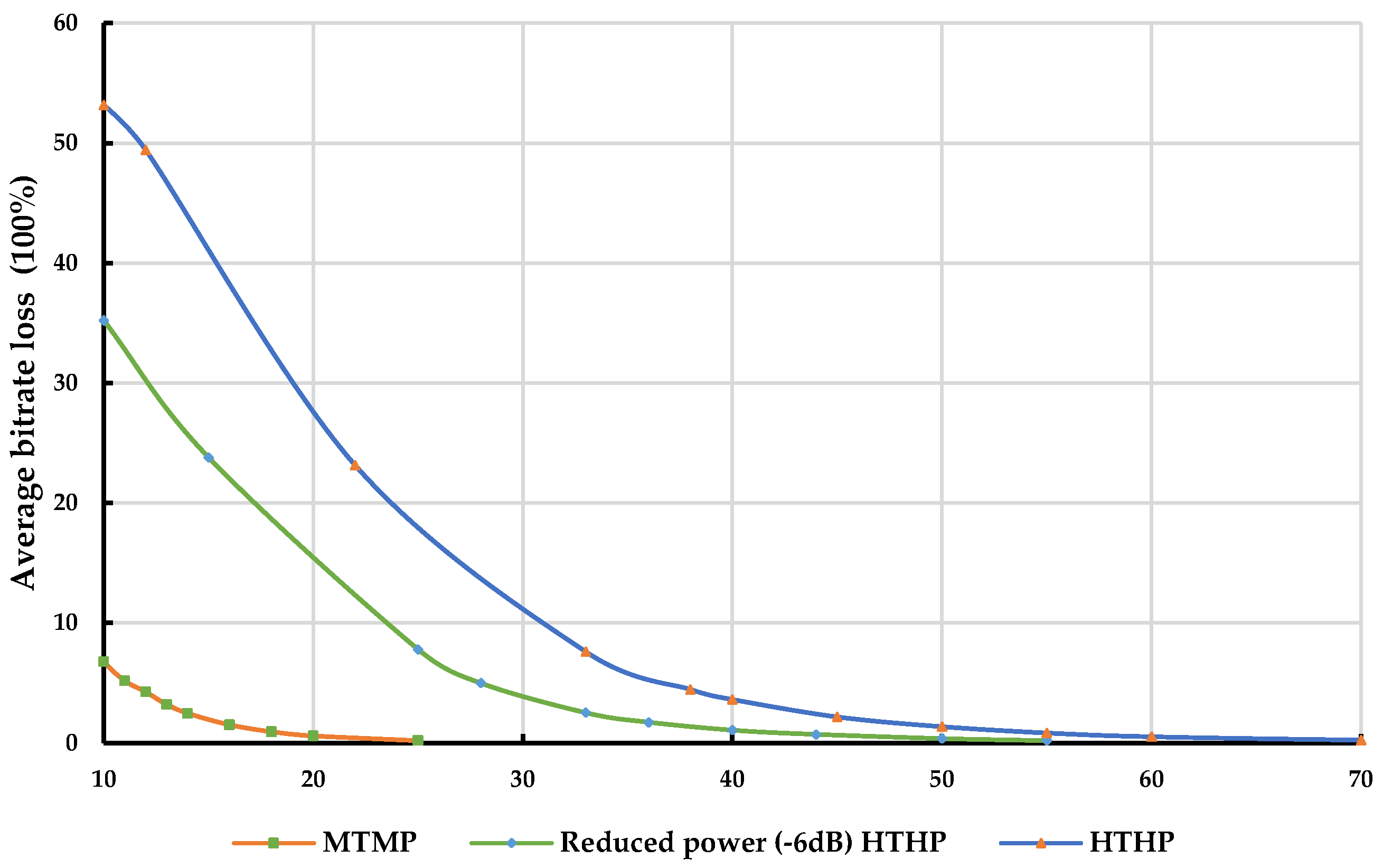
| Classes of DTTB Transmitters | Minimum Coordination Distance (km) at X% of Time | |||
|---|---|---|---|---|
| 1% | 5% | 10% | 50% | |
| MTMP | 12 | 11 | 11 | 11 |
| Reduced power HTHP | 28 | 28 | 27 | 27 |
| HTHP | 38 | 36 | 35 | 35 |
Disclaimer/Publisher’s Note: The statements, opinions and data contained in all publications are solely those of the individual author(s) and contributor(s) and not of MDPI and/or the editor(s). MDPI and/or the editor(s) disclaim responsibility for any injury to people or property resulting from any ideas, methods, instructions or products referred to in the content. |
© 2023 by the authors. Licensee MDPI, Basel, Switzerland. This article is an open access article distributed under the terms and conditions of the Creative Commons Attribution (CC BY) license (https://creativecommons.org/licenses/by/4.0/).
Share and Cite
Taha, H.; Vári, P.; Nagy, S. Co-Channel Compatibility Analysis of IMT Networks and Digital Terrestrial Television Broadcasting in the Frequency Range 470–694 MHz Based on Monte Carlo Simulation. Sensors 2023, 23, 8714. https://doi.org/10.3390/s23218714
Taha H, Vári P, Nagy S. Co-Channel Compatibility Analysis of IMT Networks and Digital Terrestrial Television Broadcasting in the Frequency Range 470–694 MHz Based on Monte Carlo Simulation. Sensors. 2023; 23(21):8714. https://doi.org/10.3390/s23218714
Chicago/Turabian StyleTaha, Hussein, Péter Vári, and Szilvia Nagy. 2023. "Co-Channel Compatibility Analysis of IMT Networks and Digital Terrestrial Television Broadcasting in the Frequency Range 470–694 MHz Based on Monte Carlo Simulation" Sensors 23, no. 21: 8714. https://doi.org/10.3390/s23218714