
Flexible and Transparent Circularly Polarized Patch Antenna for Reliable Unobtrusive Wearable Wireless Communications

 , , , , and
Abstract
:1. Introduction
2. Materials
3. Antenna Topology and Design
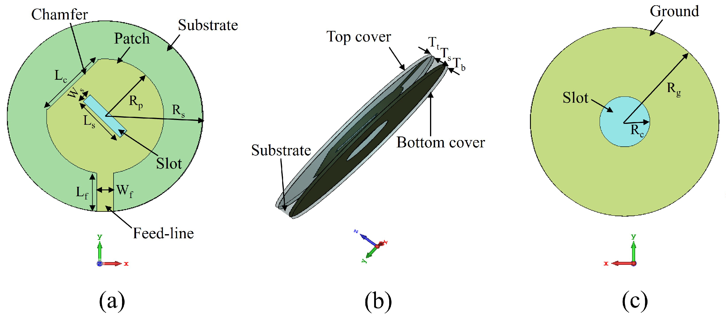
3.1. Antenna Configuration
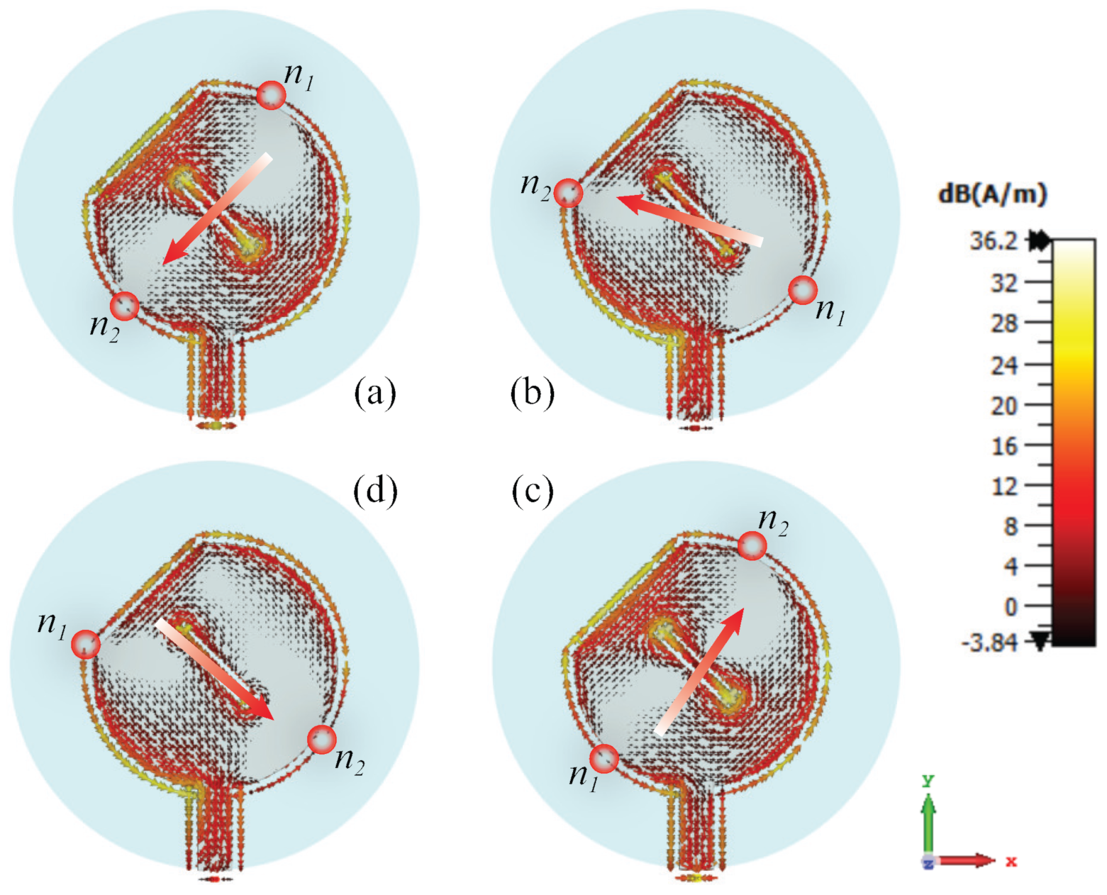
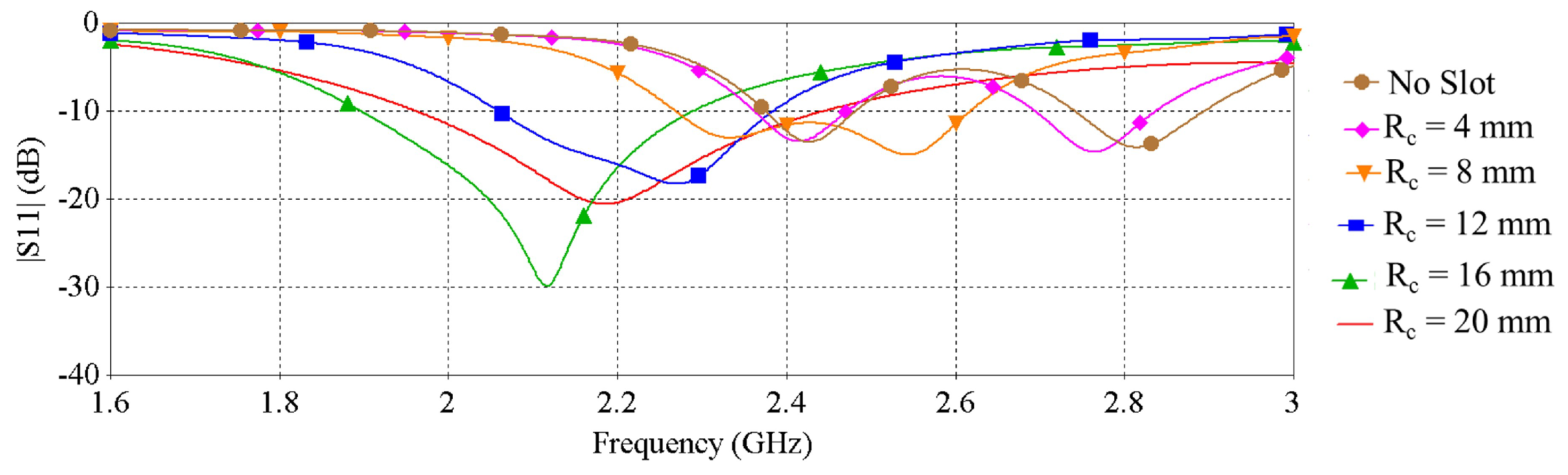
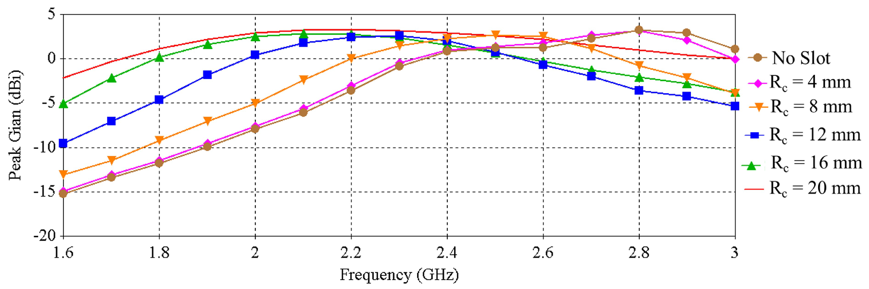
3.2. Design Methodology
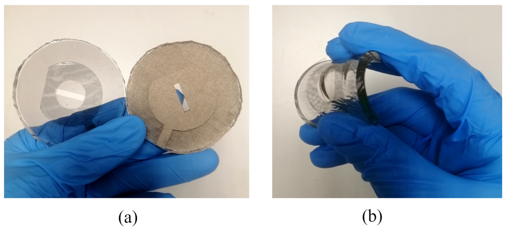
4. Prototype Fabrication
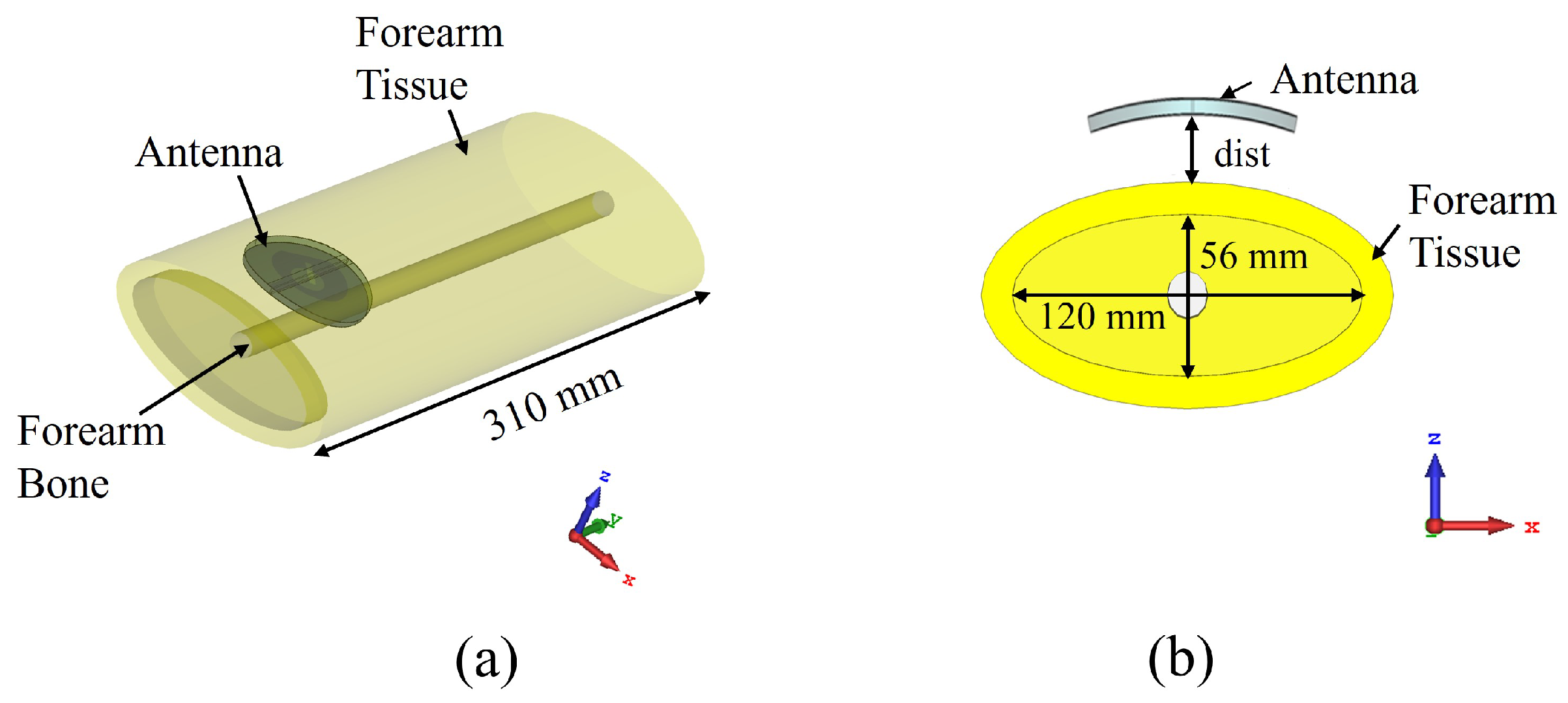
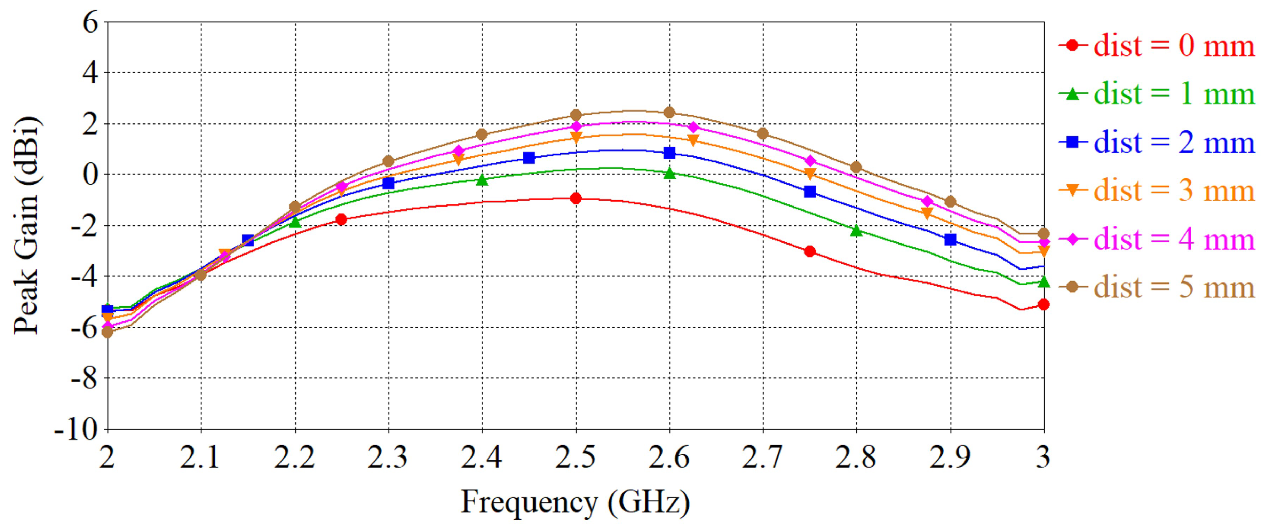
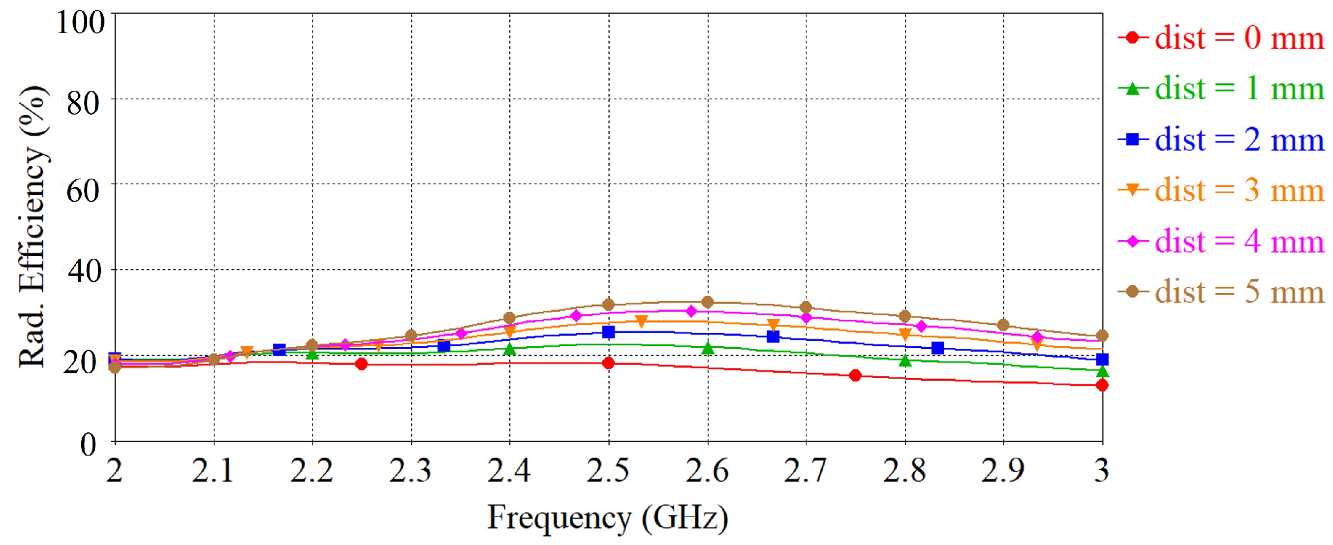
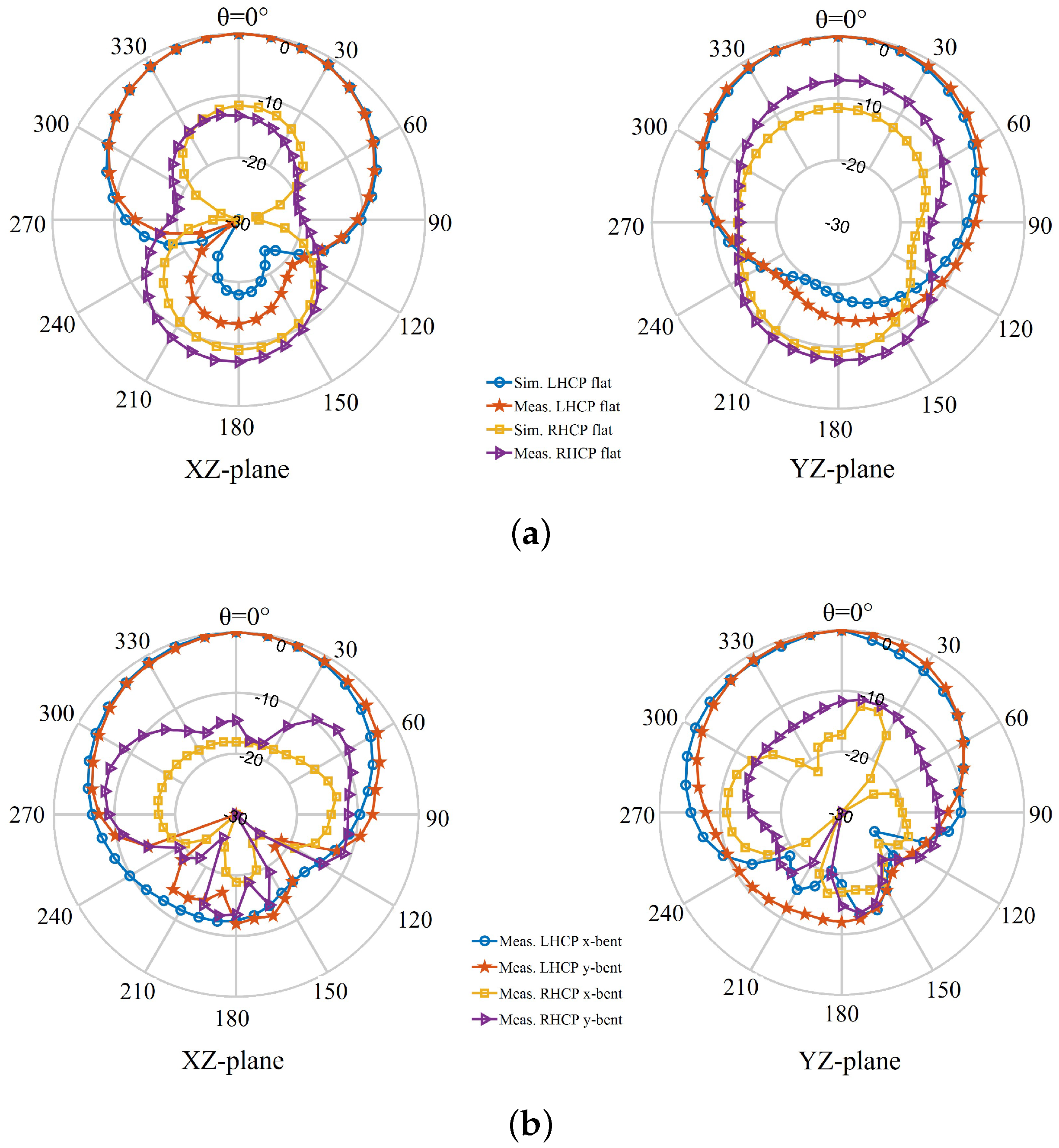
5. Performance Investigation
6. Discussion
7. Conclusions
Author Contributions
Funding
Acknowledgments
Conflicts of Interest
References
- Ding, X.; Clifton, D.; JI, N.; Lovell, N.H.; Bonato, P.; Chen, W.; Yu, X.; Xue, Z.; Xiang, T.; Long, X.; et al. Wearable Sensing and Telehealth Technology with Potential Applications in the Coronavirus Pandemic. IEEE Rev. Biomed. Eng. 2021, 14, 48–70. [Google Scholar] [CrossRef] [PubMed]
- Movassaghi, S.; Abolhasan, M.; Lipman, J.; Smith, D.; Jamalipour, A. Wireless Body Area Networks: A Survey. IEEE Commun. Surv. Tutorials 2014, 16, 1658–1686. [Google Scholar] [CrossRef]
- Guibert, M.; Massicart, A.; Chen, X.; He, H.; Torres, J.; Ukkonen, L.; Virkki, J. Washing reliability of painted, embroidered, and electro-textile wearable RFID tags. In Proceedings of the 2017 Progress in Electromagnetics Research Symposium-Fall (PIERS-FALL), Singapore, 19–22 November 2017; pp. 828–831. [Google Scholar] [CrossRef]
- Toivonen, M.; Björninen, T.; Sydänheimo, L.; Ukkonen, L.; Rahmat-Samii, Y. Impact of Moisture and Washing on the Performance of Embroidered UHF RFID Tags. IEEE Antennas Wirel. Propag. Lett. 2013, 12, 1590–1593. [Google Scholar] [CrossRef]
- Paul, D.L.; Giddens, H.; Paterson, M.G.; Hilton, G.S.; McGeehan, J.P. Impact of Body and Clothing on a Wearable Textile Dual Band Antenna at Digital Television and Wireless Communications Bands. IEEE Trans. Antennas Propag. 2013, 61, 2188–2194. [Google Scholar] [CrossRef]
- Hertleer, C.; Rogier, H.; Vallozzi, L.; Van Langenhove, L. A Textile Antenna for Off-Body Communication Integrated Into Protective Clothing for Firefighters. IEEE Trans. Antennas Propag. 2009, 57, 919–925. [Google Scholar] [CrossRef]
- Sayem, A.S.M.; Simorangkir, R.B.V.B.; Esselle, K.P.; Hashmi, R.M. Development of Robust Transparent Conformal Antennas Based on Conductive Mesh-Polymer Composite for Unobtrusive Wearable Applications. IEEE Trans. Antennas Propag. 2019, 67, 7216–7224. [Google Scholar] [CrossRef]
- Lu, J.; Chang, B. Planar Compact Square-Ring Tag Antenna with Circular Polarization for UHF RFID Applications. IEEE Trans. Antennas Propag. 2017, 65, 432–441. [Google Scholar] [CrossRef]
- Green, R.B.; Guzman, M.; Izyumskaya, N.; Ullah, B.; Hia, S.; Pitchford, J.; Timsina, R.; Avrutin, V.; Ozgur, U.; Morkoc, H.; et al. Optically Transparent Antennas and Filters: A Smart City Concept to Alleviate Infrastructure and Network Capacity Challenges. IEEE Antennas Propag. Mag. 2019, 61, 37–47. [Google Scholar] [CrossRef]
- Sayem, A.S.M.; Simorangkir, R.B.V.B.; Esselle, K.P.; Hashmi, R.M.; Liu, H. A Method to Develop Flexible Robust Optically Transparent Unidirectional Antennas Utilizing Pure Water, PDMS, and Transparent Conductive Mesh. IEEE Trans. Antennas Propag. 2020, 68, 6943–6952. [Google Scholar] [CrossRef]
- Colombel, F.; Castel, X.; Himdi, M.; Legeay, G.; Vigneron, S.; Cruz, E.M. Ultrathin metal layer, ITO film and ITO/Cu/ITO multilayer towards transparent antenna. IET Sci. Measure. Tech. 2009, 3, 229–234. [Google Scholar] [CrossRef]
- Hong, S.; Kang, S.H.; Kim, Y.; Jung, C.W. Transparent and Flexible Antenna for Wearable Glasses Applications. IEEE Trans. Antennas Propag. 2016, 64, 2797–2804. [Google Scholar] [CrossRef]
- Sheikh, S.; Shokooh-Saremi, M.; Bagheri-Mohagheghi, M. Transparent microstrip patch antenna based on fluorine-doped tin oxide deposited by spray pyrolysis technique. IET Microwaves Antennas Propag. 2015, 9, 1221–1229. [Google Scholar] [CrossRef]
- Green, R.B.; Toporkov, M.; Ullah, M.; Avrutin, V.; Ozgur, U.; Morkoc, H.; Topsakal, E. An alternative material for transparent antennas for commercial and medical applications. Microw. Opt. Technol. Lett. 2017, 59, 773–777. [Google Scholar] [CrossRef]
- Lee, S.Y.; Choo, M.; Jung, S.; Hong, W. Optically Transparent Nano-Patterned Antennas: A Review and Future Directions. Appl. Sci. 2018, 8, 901. [Google Scholar] [CrossRef] [Green Version]
- Xi, B.; Liang, X.; Chen, Q.; Wang, K.; Geng, J.; Jin, R. Optical Transparent Antenna Array Integrated with Solar Cell. IEEE Antennas Wirel. Propag. Lett. 2020, 19, 457–461. [Google Scholar] [CrossRef]
- Hautcoeur, J.; Talbi, L.; Hettak, K.; Nedil, M. 60 GHz optically transparent microstrip antenna made of meshed AuGL material. IET Microwaves Antennas Propag. 2014, 8, 1091–1096. [Google Scholar] [CrossRef]
- Kim, W.K.; Lee, S.; Hee Lee, D.; Hee Park, I.; Seong Bae, J.; Woo Lee, T.; Kim, J.Y.; Hun Park, J.; Chan Cho, Y.; Ryong Cho, C.; et al. Cu Mesh for Flexible Transparent Conductive Electrodes. Sci. Rep. 2015, 5, 10715. [Google Scholar] [CrossRef] [Green Version]
- Sayem, A.S.M.; Esselle, K.P.; Hashmi, R.M.; Liu, H. Experimental studies of the robustness of the conductive-mesh-polymer composite towards the development of conformal and transparent antennas. Smart Mater. Struct. 2020, 29, 085015. [Google Scholar] [CrossRef]
- Zandvakili, M.; Honari, M.M.; Sameoto, D.; Mousavi, P. Microfluidic liquid metal based mechanically reconfigurable antenna using reversible gecko adhesive based bonding. In Proceedings of the 2016 IEEE MTT-S International Microwave Symposium (IMS), San Francisco, CA, USA, 22–27 May 2016; pp. 1–4. [Google Scholar] [CrossRef]
- Cheng, S.; Rydberg, A.; Hjort, K.; Wu, Z. Liquid metal stretchable unbalanced loop antenna. Appl. Phys. Lett. 2009, 94, 144103. [Google Scholar] [CrossRef]
- Jang, T.; Zhang, C.; Youn, H.; Zhou, J.; Guo, L.J. Semitransparent and Flexible Mechanically Reconfigurable Electrically Small Antennas Based on Tortuous Metallic Micromesh. IEEE Trans. Antennas Propag. 2017, 65, 150–158. [Google Scholar] [CrossRef]
- Sayem, A.S.M.; Esselle, K.P.; Hashmi, R.M. Increasing the transparency of compact flexible antennas using defected ground structure for unobtrusive wearable technologies. IET Microwaves Antennas Propag. 2020, 14, 1869–1877. [Google Scholar] [CrossRef]
- Sayem, A.S.M.; Simorangkir, R.B.V.B.; Esselle, K.P.; Thalakotuna, D.N.; Lalbakhsh, A. An Electronically-Tunable, Flexible, and Transparent Antenna with Unidirectional Radiation Pattern. IEEE Access 2021, 9, 147042–147053. [Google Scholar] [CrossRef]
- Sayem, A.S.M.; Le, D.; Simorangkir, R.B.V.B.; Björninen, T.; Esselle, K.P.; Hashmi, R.M.; Zhadobov, M. Optically Transparent Flexible Robust Circularly Polarized Antenna for UHF RFID Tags. IEEE Antennas Wirel. Propag. Lett. 2020, 19, 2334–2338. [Google Scholar] [CrossRef]
- Chen, H.; Tsai, C.; Sim, C.; Kuo, C. Circularly Polarized Loop Tag Antenna for Long Reading Range RFID Applications. IEEE Antennas Wirel. Propag. Lett. 2013, 12, 1460–1463. [Google Scholar] [CrossRef]
- Kumar, S.; Nandan, D.; Srivastava, K.; Kumar, S.; Singh, H.; Marey, M.; Mostafa, H.; Kanaujia, B.K. Wideband Circularly Polarized Textile MIMO Antenna for Wearable Applications. IEEE Access 2021, 9, 108601–108613. [Google Scholar] [CrossRef]
- Hu, X.; Yan, S.; Zhang, J.; Volski, V.; Vandenbosch, G.A.E. Omni-Directional Circularly Polarized Button Antenna for 5 GHz WBAN Applications. IEEE Trans. Antennas Propag. 2021, 69, 5054–5059. [Google Scholar] [CrossRef]
- Yin, X.; Chen, S.J.; Fumeaux, C. Wearable Dual-Band Dual-Polarization Button Antenna for WBAN Applications. IEEE Antennas Wirel. Propag. Lett. 2020, 19, 2240–2244. [Google Scholar] [CrossRef]
- Ullah, U.; Mabrouk, I.B.; Koziel, S. A Compact Circularly Polarized Antenna with Directional Pattern for Wearable Off-Body Communications. IEEE Antennas Wirel. Propag. Lett. 2019, 18, 2523–2527. [Google Scholar] [CrossRef]
- Zu, H.R.; Wu, B.; Zhang, Y.H.; Zhao, Y.T.; Song, R.G.; He, D.P. Circularly Polarized Wearable Antenna with Low Profile and Low Specific Absorption Rate Using Highly Conductive Graphene Film. IEEE Antennas Wirel. Propag. Lett. 2020, 19, 2354–2358. [Google Scholar] [CrossRef]
- Hu, X.; Yan, S.; Vandenbosch, G.A.E. Compact Circularly Polarized Wearable Button Antenna with Broadside Pattern for U-NII Worldwide Band Applications. IEEE Trans. Antennas Propag. 2019, 67, 1341–1345. [Google Scholar] [CrossRef]
- Jiang, Z.H.; Gregory, M.D.; Werner, D.H. Design and Experimental Investigation of a Compact Circularly Polarized Integrated Filtering Antenna for Wearable Biotelemetric Devices. IEEE Trans. Biomed. Circuits Syst. 2016, 10, 328–338. [Google Scholar] [CrossRef]
- Jiang, Z.H.; Werner, D.H. A Compact, Wideband Circularly Polarized Co-designed Filtering Antenna and Its Application for Wearable Devices with Low SAR. IEEE Trans. Antennas Propag. 2015, 63, 3808–3818. [Google Scholar] [CrossRef]
- Jiang, Z.H.; Cui, Z.; Yue, T.; Zhu, Y.; Werner, D.H. Compact, Highly Efficient, and Fully Flexible Circularly Polarized Antenna Enabled by Silver Nanowires for Wireless Body-Area Networks. IEEE Trans. Biomed. Circuits Syst. 2017, 11, 920–932. [Google Scholar] [CrossRef]
- Li, J.; Jiang, Y.; Zhao, X. Circularly Polarized Wearable Antenna Based on NinjaFlex-Embedded Conductive Fabric. Int. J. Antennas Propag. 2019, 2019, 3059480. [Google Scholar] [CrossRef]
- Locher, I.; Klemm, M.; Kirstein, T.; Troster, G. Design and Characterization of Purely Textile Patch Antennas. IEEE Trans. Adv. Packag. 2006, 29, 777–788. [Google Scholar] [CrossRef] [Green Version]
- Kaivanto, E.K.; Berg, M.; Salonen, E.; de Maagt, P. Wearable Circularly Polarized Antenna for Personal Satellite Communication and Navigation. IEEE Trans. Antennas Propag. 2011, 59, 4490–4496. [Google Scholar] [CrossRef]
- Sun, S.; Pan, Z.; Yang, F.K.; Huang, Y.; Zhao, B. A transparent silica colloidal crystal/PDMS composite and its application for crack suppression of metallic coatings. J. Colloid Interface Sci. 2016, 461, 136–143. [Google Scholar] [CrossRef]
- Simorangkir, R.B.V.B.; Yang, Y.; Hashmi, R.M.; Björninen, T.; Esselle, K.P.; Ukkonen, L. Polydimethylsiloxane-Embedded Conductive Fabric: Characterization and Application for Realization of Robust Passive and Active Flexible Wearable Antennas. IEEE Access 2018, 6, 48102–48112. [Google Scholar] [CrossRef]
- Hautcoeur, J.; Colombel, F.; Castel, X.; Himdi, M.; Cruz, E.M. Radiofrequency performances of transparent ultra-wideband antennas. Prog. Electromag. Res. C 2011, 22, 259–271. [Google Scholar] [CrossRef] [Green Version]
- Yasin, T.; Baktur, R. Inkjet printed patch antennas on transparent substrates. In Proceedings of the 2010 IEEE Antennas and Propagation Society International Symposium, Toronto, ON, Canada, 11–17 July 2010; pp. 1–4. [Google Scholar]
- Mohamadzade, B.; Simorangkir, R.B.V.B.; Hashmi, R.M.; Gharaei, R.; Lalbakhsh, A.; Shrestha, S.; Zhadobov, M.; Sauleau, R. A Conformal, Dynamic Pattern-Reconfigurable Antenna Using Conductive Textile-Polymer Composite. IEEE Trans. Antennas Propag. 2021, 69, 6175–6184. [Google Scholar] [CrossRef]
- Pinapati, S.P.; Kaufmann, T.; Linke, I.; Ranasinghe, D.; Fumeaux, C. Connection strategies for wearable microwave transmission lines and antennas. In Proceedings of the 2015 International Symposium on Antennas and Propagation (ISAP), Hobart, Australia, 9–12 November 2015; pp. 1–4. [Google Scholar]
- Kumar, S.; Buckley, J.L.; Barton, J.; Pigeon, M.; Newberry, R.; Rodencal, M.; Hajzeraj, A.; Hannon, T.; Rogers, K.; Casey, D.; et al. A Wristwatch-Based Wireless Sensor Platform for IoT Health Monitoring Applications. Sensors 2020, 20, 1675. [Google Scholar] [CrossRef] [Green Version]
- Chen, S.J.; Fumeaux, C.; Ranasinghe, D.C.; Kaufmann, T. Paired Snap-On Buttons Connections for Balanced Antennas in Wearable Systems. IEEE Antennas Wirel. Propag. Lett. 2015, 14, 1498–1501. [Google Scholar] [CrossRef]
- Seager, R.; Chauraya, A.; Zhang, S.; Whittow, W.; Vardaxoglou, Y. Flexible radio frequency connectors for textile electronics. Electron. Lett. 2013, 49, 1371–1373. [Google Scholar] [CrossRef] [Green Version]
- Speag Phantom Arm, SHO-GFPC-V1. Available online: https://speag.swiss/products/em-phantoms/ctia-sub-10/sho-gfpc-v1/ (accessed on 12 December 2021).
- Lee, H.; Tak, J.; Choi, J. Wearable Antenna Integrated into Military Berets for Indoor/Outdoor Positioning System. IEEE Antennas Wirel. Propag. Lett. 2017, 16, 1919–1922. [Google Scholar] [CrossRef]
- Soh, P.J.; Vandenbosch, G.; Wee, F.H.; van den Bosch, A.; Martinez-Vazquez, M.; Schreurs, D. Specific Absorption Rate (SAR) Evaluation of Textile Antennas. IEEE Antennas Propag. Mag. 2015, 57, 229–240. [Google Scholar] [CrossRef]
- IEEE Std C95.1-2019 (Revision of IEEE Std C95.1-2005/ Incorporates IEEE Std C95.1-2019/Cor 1-2019); IEEE Standard for Safety Levels with Respect to Human Exposure to Electric, Magnetic, and Electromagnetic Fields, 0 Hz to 300 GHz. IEEE: Piscataway, NJ, USA, 2019; pp. 1–312. [CrossRef]
- Alemaryeen, A.; Noghanian, S. On-Body Low-Profile Textile Antenna with Artificial Magnetic Conductor. IEEE Trans. Antennas Propag. 2019, 67, 3649–3656. [Google Scholar] [CrossRef]
- Kaim, V.; Kanaujia, B.K.; Rambabu, K. Quadrilateral Spatial Diversity Circularly Polarized MIMO Cubic Implantable Antenna System for Biotelemetry. IEEE Trans. Antennas Propag. 2021, 69, 1260–1272. [Google Scholar] [CrossRef]
- Bayram, Y.; Zhou, Y.; Shim, B.S.; Xu, S.; Zhu, J.; Kotov, N.A.; Volakis, J.L. E-textile conductors and polymer composites for conformal lightweight antennas. IEEE Trans. Antennas Propag. 2010, 58, 2732–2736. [Google Scholar] [CrossRef]


| Parameter | Description | Value (mm) |
|---|---|---|
| Rp | Radius of the patch | 18 |
| Rs | Radius of the substrate | 30 |
| Rg | Radius of the ground plane | 30 |
| Rc | Radius of the slot in the ground plane | 8 |
| Ls | Length of the slot in the patch | 16 |
| Ws | Width of the slot in the patch | 3 |
| Lc | length of the chamfer | 22 |
| Lf | Length of the feed-line | 12.17 |
| Wf | Width of the feed-line | 5 |
| Tt | Thickness of the top PDMS cover | 0.2 |
| Tb | Thickness of the bottom PDMS cover | 0.2 |
| Ts | Thickness of the substrate | 3 |
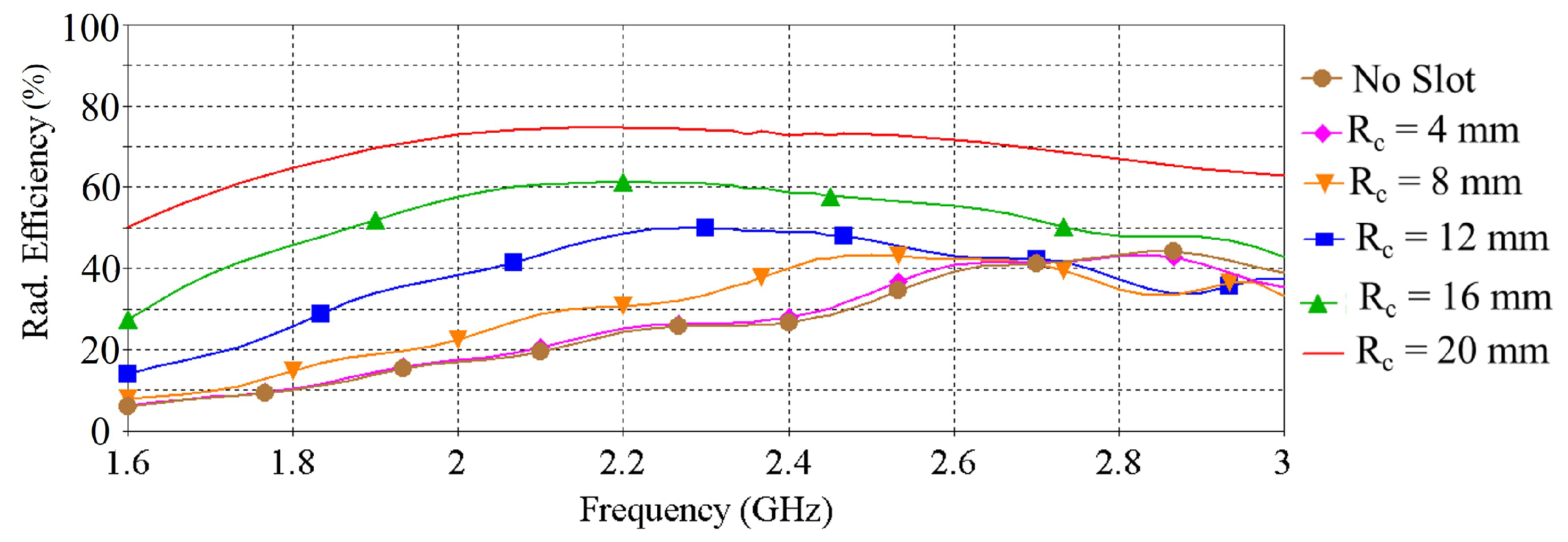
| Rc (mm) | 0 | 4 | 8 | 12 | 16 | 20 |
| Res. Freq. (GHz) | 2.63 | 2.57 | 2.45 | 2.26 | 2.12 | 2.2 |
| Peak Gain (dBi) | 1.54 | 1.63 | 2.44 | 2.53 | 2.78 | 3.24 |
| Rad. Effi. (%) | 40 | 39.7 | 42.6 | 49.8 | 60.1 | 74.5 |
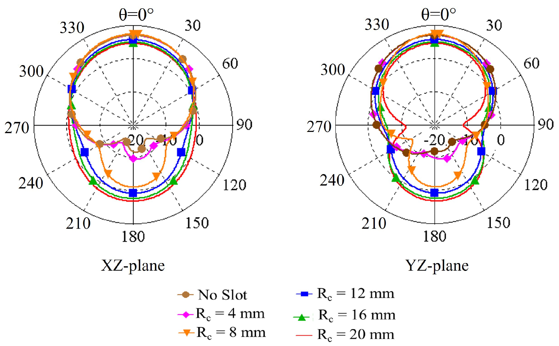
| F/B (dB): XZ-plane | 16.1 | 14.6 | 8.6 | 5 | 2.8 | 1.6 |
| F/B (dB): YZ-plane | 16.1 | 14.6 | 8.6 | 5 | 2.7 | 1.5 |
| Tissue | Relative Permittivity | Conductivity (S/m) |
|---|---|---|
| Bone | 11.4 | 0.39 |
| Muscle | 52.73 | 1.74 |
| Fat | 5.28 | 0.1 |
| Skin | 37.88 | 1.44 |
| Ref. | Freq. (GHz) | Footprint | Profile | Gain (dBi) | Effi. (%) | 3-dB AR BW (%) | Trans. | Flex. |
|---|---|---|---|---|---|---|---|---|
| [6] | 2.45 | 0.66 | 0.03 | 6.03 | 62 | 2.18 | No | Yes |
| [27] | 6.15 | 0.58 | 0.02 | 5.7 | 80 | 30.8 | No | Yes |
| [28] | 5.8 | 0.23 | 0.2 | 2.1 | 72.6 | 2.93 | No | No |
| [29] | 2.45 5.8 | 0.123 | 0.22 | 2.2 8.6 | NA | 31.4 | No | No |
| [30] | 5.16 | 0.05 | 0.25 | 6.2 | 90 | 18.3 | No | No |
| [31] | 5.8 | 0.23 | 0.05 | 6 | 80 | 1.4 | No | Yes |
| [32] | 5.5 | 0.1 | 0.22 | 3.5 | 79.9 | 6.55 | No | Yes |
| [33] | 2.4 | 0.2 | 0.045 | 3.5 | 58 | 2.4 | No | No |
| [34] | 4 | 0.28 | 0.07 | 5.2 | 80 | 12.5 | No | No |
| [35] | 2.4 | 0.17 | 0.045 | 5.2 | 79 | 2.72 | No | Yes |
| [36] | 2.45 | 0.24 | 0.025 | 1.8 | 30.7 | 2.86 | No | Yes |
| [37] | 2.4 | 0.95 | 0.03 | 4.4 | 34.7 | 2.96 | No | Yes |
| [38] | 1.575 1.621 | 0.27 | NA | 6.2 | 70 | 1.23 | No | Yes |
| This work | 2.4 | 0.19 | 0.028 | 2.5 | 42.26 | 4.16 | Yes | Yes |
Publisher’s Note: MDPI stays neutral with regard to jurisdictional claims in published maps and institutional affiliations. |
© 2022 by the authors. Licensee MDPI, Basel, Switzerland. This article is an open access article distributed under the terms and conditions of the Creative Commons Attribution (CC BY) license (https://creativecommons.org/licenses/by/4.0/).
Share and Cite
Sayem, A.S.M.; Simorangkir, R.B.V.B.; Esselle, K.P.; Lalbakhsh, A.; Gawade, D.R.; O’Flynn, B.; Buckley, J.L. Flexible and Transparent Circularly Polarized Patch Antenna for Reliable Unobtrusive Wearable Wireless Communications. Sensors 2022, 22, 1276. https://doi.org/10.3390/s22031276
Sayem ASM, Simorangkir RBVB, Esselle KP, Lalbakhsh A, Gawade DR, O’Flynn B, Buckley JL. Flexible and Transparent Circularly Polarized Patch Antenna for Reliable Unobtrusive Wearable Wireless Communications. Sensors. 2022; 22(3):1276. https://doi.org/10.3390/s22031276
Chicago/Turabian StyleSayem, Abu Sadat Md., Roy B. V. B. Simorangkir, Karu P. Esselle, Ali Lalbakhsh, Dinesh R. Gawade, Brendan O’Flynn, and John L. Buckley. 2022. "Flexible and Transparent Circularly Polarized Patch Antenna for Reliable Unobtrusive Wearable Wireless Communications" Sensors 22, no. 3: 1276. https://doi.org/10.3390/s22031276