The Design of a Frame-Like ZnO FBAR Sensor for Achieving Uniform Mass Sensitivity Distributions


1
State Key Laboratory of Mechanics and Control of Mechanical Structures, College of Aerospace Engineering, Nanjing University of Aeronautics and Astronautics, Nanjing 210016, China
2
Piezoelectric Device Laboratory, School of Mechanical Engineering and Mechanics, Ningbo University, Ningbo 315211, China
*
Author to whom correspondence should be addressed.
Sensors 2020, 20(8), 2408; https://doi.org/10.3390/s20082408
Submission received: 26 February 2020
/
Revised: 4 April 2020
/
Accepted: 20 April 2020
/
Published: 23 April 2020
(This article belongs to the Special Issue Surface Acoustic Wave and Bulk Acoustic Wave Sensors 2019)
Abstract
:In this paper, an infinite circular ZnO thin film bulk acoustic resonator (FBAR) with a frame-like electrode operating at the thickness-extensional (TE) mode is studied. Two-dimensional scalar differential equations established for the problem in the Cartesian coordinate system are successfully solved by transforming them into normal Bessel equations and modified Bessel equations in the cylindrical coordinate system. Resonant frequencies and vibration distributions are obtained for this frame-like FBAR sensor. A nearly uniform mass sensitivity distribution in the active area is achieved by designing proper electrode size and mass ratio of the driving electrode to the ZnO film. Numerical results show that compared with the reported ring electrode FBAR sensor, the novel frame-like electrode FBAR can achieve a maximum optimization ratio (up to 97.90%) on the uniformity of the mass sensitivity distribution in the active area under the same structural parameters, which is also higher than the optimization ratio 77.63% obtained by the reported double-ring electrode design. Moreover, the mechanism to achieve a very uniform mass sensitivity distribution in the active area by the frame-like electrode is explained in detail according to dispersion curves. Namely, when the resonant frequency of the FBAR sensor is close to the cut-off frequency of the active region in the dispersion curve, the mass sensitivity distribution is nearly uniform. These conclusions provide a theoretical guidance for the design and optimization of ZnO FBAR mass sensors with high performance.
1. Introduction
In the past decades, since the relationship between the frequency changes of a quartz crystal and the mass added to its surface was discovered [1], quartz crystal microbalances (QCMs) based on quartz crystal resonators (QCRs) have been widely used in the field of mass sensing [2,3,4,5]. However, since the thickness of a quartz crystal plate is usually in the order of millimeter, a QCR usually operates at a frequency of megahertz, which limits the mass sensitivity of QCMs [6,7]. At present, piezoelectric thin film bulk acoustic resonators (FBARs) made from ZnO or AlN film have been proposed and applied in telecommunication field. As a result of its small size in thickness direction, FBARs can operate at an ultra-high frequency of gigahertz, and hence the FBAR sensors can achieve a higher mass sensitivity than traditional QCMs [8,9].
In addition to higher mass sensitivity, uniform mass sensitivity distribution is also a key influence factor to improve the performance of the sensors [10,11,12,13]. The working principle of mass sensors is to detect the frequency changes of the sensor induced by the added mass deposited on the sensor’s surface. The relation between frequency shifts and the added mass has the relation as [10]
where is the frequency change and is the added mass [14,15]. is the mass sensitivity function, which is written as [10]
where is the displacement distribution function of the sensor. is the Sauerbrey’s sensitivity constant. It can be seen from Equation (1) that if is uniform, the frequency shifts of the mass sensor only depend on the added mass. Otherwise, the frequency shifts are also dependent on , which is a function of the position of the added mass. Therefore, it is necessary to achieve the uniform mass sensitivity distribution function . However, for typical QCMs and FBARs, the mass sensitivity distribution is usually quite non-uniform and has a bell-shaped contour in the active area [16,17]. Therefore, many works were carried out to achieve more uniform mass sensitivity distributions in QCM and FBAR sensors. For example, in QCMs some methods by optimizing the electrode geometry to obtain flatter mass sensitivity curve were proposed, such as the “n-m” electrodes [10], ring [18], dot-ring, and double-ring electrodes [11]. Similarly, some researchers also made some positive explorations in FBAR mass sensors. Zhao et al. optimized the parameters of the rectangular ring electrodes in a ZnO FBAR sensor by using the Ritz method based on the two-dimensional scalar equations, and obtained a relatively flat displacement curve by adjusting the electrode size and mass ratio in detail [19]. Moreover, Liu et al. studied the displacement distribution of a circular ring electrode FBARs by analytical solution and discovered the effects of electrode size and inertia on the displacement distributions [20]. However, the ring electrode FBARs, whether circular or rectangular, can only produce bimodal distributions in the electrode region, which means that the mass sensitivity curves cannot satisfy the actual requirement, i.e., very uniform mass sensitivity distributions. Therefore, it is necessary to propose a new structure to achieve a more uniform mass sensitivity distribution.
In this paper, a frame-like electrode FBAR is proposed to obtain a more uniform mass sensitivity distribution. The thickness-extensional (TE) mode of a circular frame-like electrode FBAR is studied theoretically based on the two-dimensional scalar equations derived by Tiersten and Stevens [21]. According to the coordinate transformation, the two-dimensional scalar equations in the Cartesian coordinate system are transformed to normal Bessel equations and modified Bessel equation in cylindrical coordinate system. Meanwhile, a very uniform mass sensitivity distribution is achieved by optimizing the electrode size and mass ratio. The mechanism to achieve the very uniform mass sensitivity distribution in the active area by the frame-like electrode is also discussed by studying the dispersion curves in different areas of the FBAR sensor. These results can provide a fundamental reference to the structural design and optimization of FBAR mass sensors.
2. Governing Equations
This paper considers a ZnO FBAR mass sensor with its top surface covered by a circular frame-like electrode, as shown in Figure 1. For the ZnO FBAR, the main operating mode is TE mode. Considering the time-harmonic free vibration at a resonant frequency in this FBAR sensor, the main displacement component of the nth thickness-extensional mode can be approximately written as [21]
where is the displacement variations of the TE mode in the direction. The in-plane displacement variations of the TE mode is described by , governed by the two-dimensional scalar differential equations derived by Tiersten and Stevens [21]. These scalar equations are slightly different for the electroded area and the unelectroded area.
In the outside area without a driving electrode, from Equation (6.2) of [21], the governing equation is
In the overlap area with the thicker driving electrode, is governed by
Similarly, in the active area with a thinner driving electrode, the governing equation is
where is the mass density of the thin film and is the resonant frequency. is the acoustic wavenumber of TE vibration, which is distinct under different electrode coverings. is related to the material constants of thin film. Mn is determined by the material constants of the electrodes, thin film and Si substance. The calculations of them are given in the appendix of [16].
For a convenient simulation, we transform the Cartesian coordinate system into the cylindrical coordinate system. Introducing the coordinate transformation
and denoting
then Equations (4)–(6) can be written as
Then denoting
we obtain the following three equations in form of Bessel equation and modified Bessel equation
Further, we introduce
and then Equation (11) can be written as the following standard Bessel equations and modified Bessel equation
3. Analytical Solution
Considering the infinite ZnO FBAR mass sensor in Figure 1, the corresponding continuity conditions and boundary conditions are separately
The general solutions of the Bessel equation and modified Bessel equation in Equation (13) satisfying Equation (14a) and (14d) can be written as
where A, B, C, and D are undetermined constants. Jm and Ym are the mth-order Bessel function of the first kind and second kind, respectively. Km is the mth-order modified Bessel function of the second kind. Substitution of Equation (15) into the continuity conditions in Equation (14b) and (14c) gives four linear homogeneous equations for the undetermined constants A, B, C, and D. For the existence of nontrivial solutions, the determinant of the coefficient matrix of the equations has to vanish, which gives the frequency equation. The nontrivial solutions of A, B, C, and D determine the corresponding vibration modes. Then substituting Equation (15) into Equation (2), we can obtain the mass sensitivity curves of the frame-like electrode FBAR.
4. Numerical Examples and Discussions
As a numerical example, we consider a circular infinite ZnO FBAR mass sensor with a frame-like driving electrode in Figure 1 operating at the fundamental TE mode with n = 1 and m = 0. The thickness of the ZnO film is chosen as and the substrate layer thickness is fixed as . The mass ratio between the ground electrode and the film is fixed to be . The material constants of ZnO thin film, Si substrate, and Au electrodes can be found in [22].
4.1. Validity of the Novel Frame-Like Electrode Design
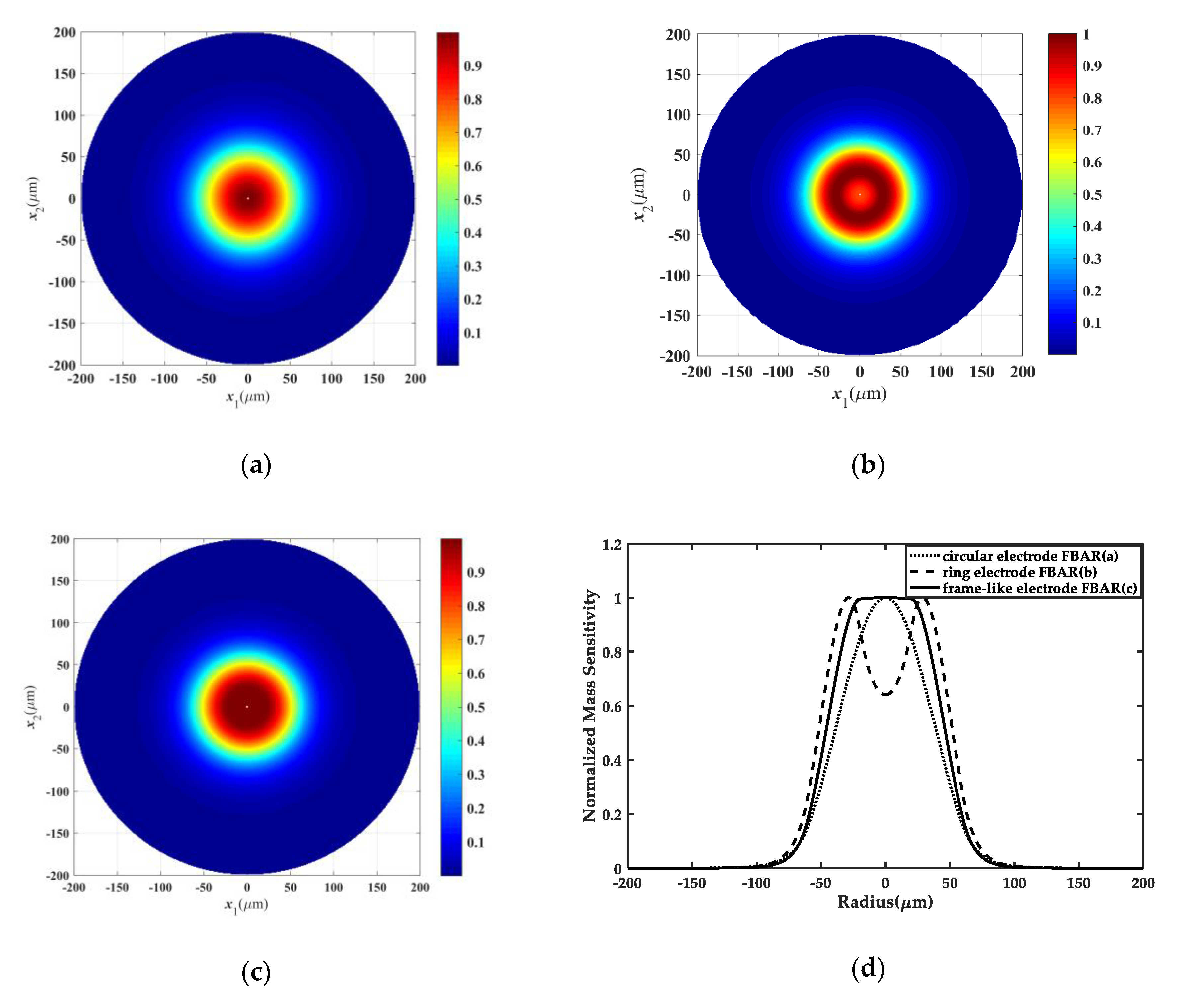
In this section, we aim to check the validity of the novel frame-like electrode designing in a ZnO FBAR mass sensor through comparing the mass sensitivity distributions of a normal circular electrode FBAR and a ring electrode FBAR with those of a frame-like electrode FBAR. For the normal circular FBAR, the mass ratio of the driving electrode to the film is selected as , and the radius of the circular electrode is . For the frame-like electrode FBAR, the mass ratio of the active driving electrode to the ZnO thin film is equal to the mass ratio of the normal circular FBAR, but in the overlap area of the frame-like electrode FBAR is equal to 0.04, which is the same as the mass ratio in the ring electrode FBAR. According to , the value of can be simply achieved by altering the overlap thickness . In addition, the electrode radii of the active and overlap areas are and , respectively.
Figure 2a–c illustrate the TE vibration modes in the normal circular electrode FBAR, the ring electrode FBAR and the frame-like electrode FBAR, respectively. Figure 2d shows the normalized mass sensitivity distributions of these three cases. Obviously, compared with the bell-shaped mass sensitivity curve of the normal circular electrode FBAR and the bimodal distribution of the ring electrode FBAR, the frame-like electrode FBAR can produce a nearly uniform mass sensitivity distribution in the active area, which is desirable in real mass sensor applications.
4.2. Effect of Structural Parameters of the Frame-Like Electrode
In Section 4.1, we have concluded that FBAR with the frame-like electrode can obtain a nearly uniform mass sensitivity distribution in the active region. In this section, we further study the influence of the structural size of the frame-like electrode and the mass ratio to achieve more uniform mass sensitivity distributions, respectively. The values of the structural parameters are the same as those used in Section 4.1 except for ,, and . These three parameters will be given in later specific analysis.
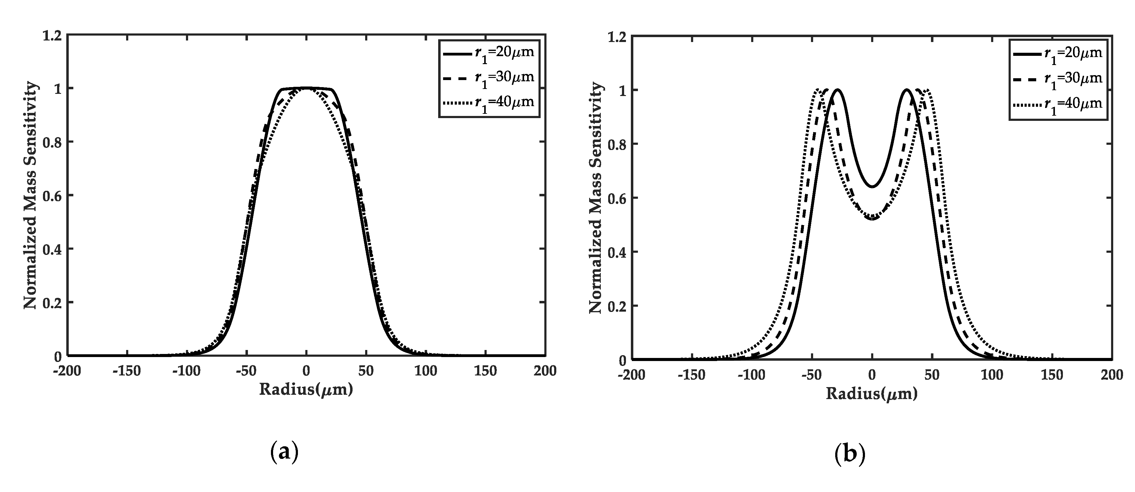
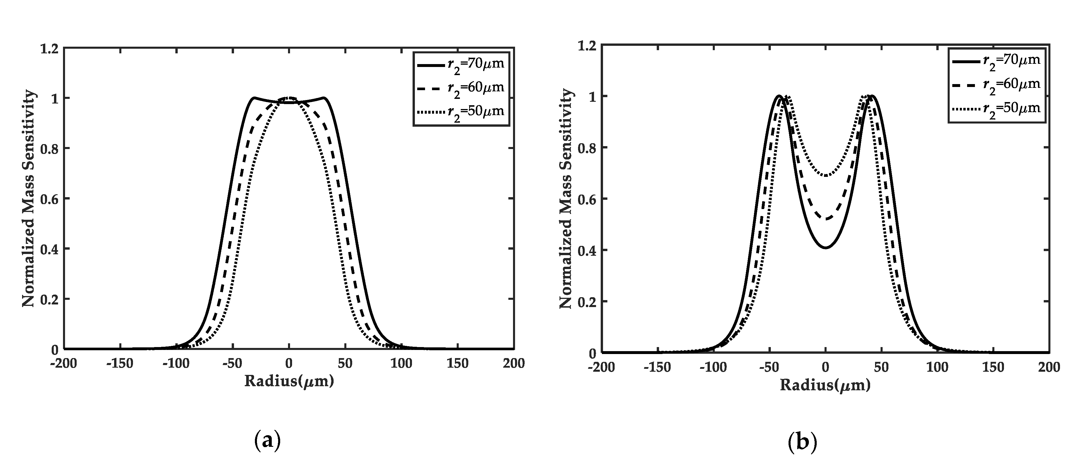
Figure 3a and Figure 4a demonstrate the mass sensitivity distributions along the direction of the frame-like electrode FBAR under different inner or outer radii of the electrode, respectively. It can be seen that the uniformity of the mass sensitivity curves in the active area depends on the values of and . For with 20 in Figure 3a and with 70 in Figure 4a, the mass sensitivity distribution of the central region is nearly uniform, which is of benefit to mass sensing. In addition, compared to the ring electrode FBAR in Figure 3b and Figure 4b [20], we can clearly find that the frame-like electrode FBAR has a greater advantage over the reported ring electrode FBAR in achieving the mass sensitivity platform in the active electrode region when the electrode parameters are fixed. Quantitatively, this advantage can also be demonstrated by the mass sensitivity amplitude deviation Δ in Table 1. When Δ gets closer to 0, the mass sensitivity distribution becomes more and more uniform. Particularly, when electrode parameters are selected as , , and , the optimization rate on the uniformity of the mass sensitivity can be up to 97.90%, which is much higher than the optimization rate 77.63% obtained by the reported double-ring electrode design [11]. These results further prove the superiority of the frame-like electrode in achieving uniform mass sensitivity distributions.
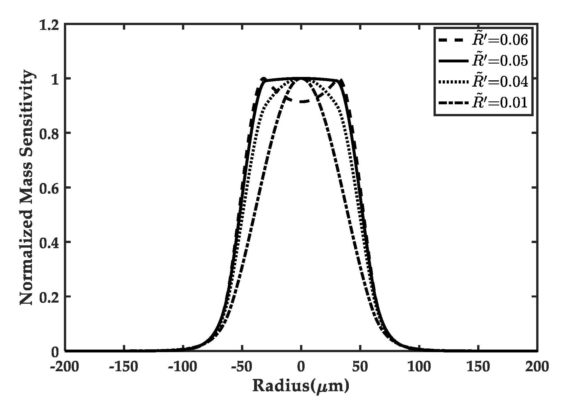
In Figure 5, the effect of the overlap driving electrode/ZnO thin film mass ratio on mass sensitivity distributions is studied. The frequency f and mass sensitivity amplitude deviations ΔF corresponding to each case are listed in Table 2. It is obvious that the mass ratio can strongly affect the mass sensitivity distributions. With the decreasing of the mass ratio , the shapes of the mass sensitivity distributions along direction alter from a bimodality to a platform and then to a bell-shape, and the deviations ΔF change from large to small and then to large. Hence, if an appropriate mass ratio is taken in a real structural design, like , the difference ΔF will be closer to zero and a nearly flat mass sensitivity distribution in the active area will be successfully obtained.
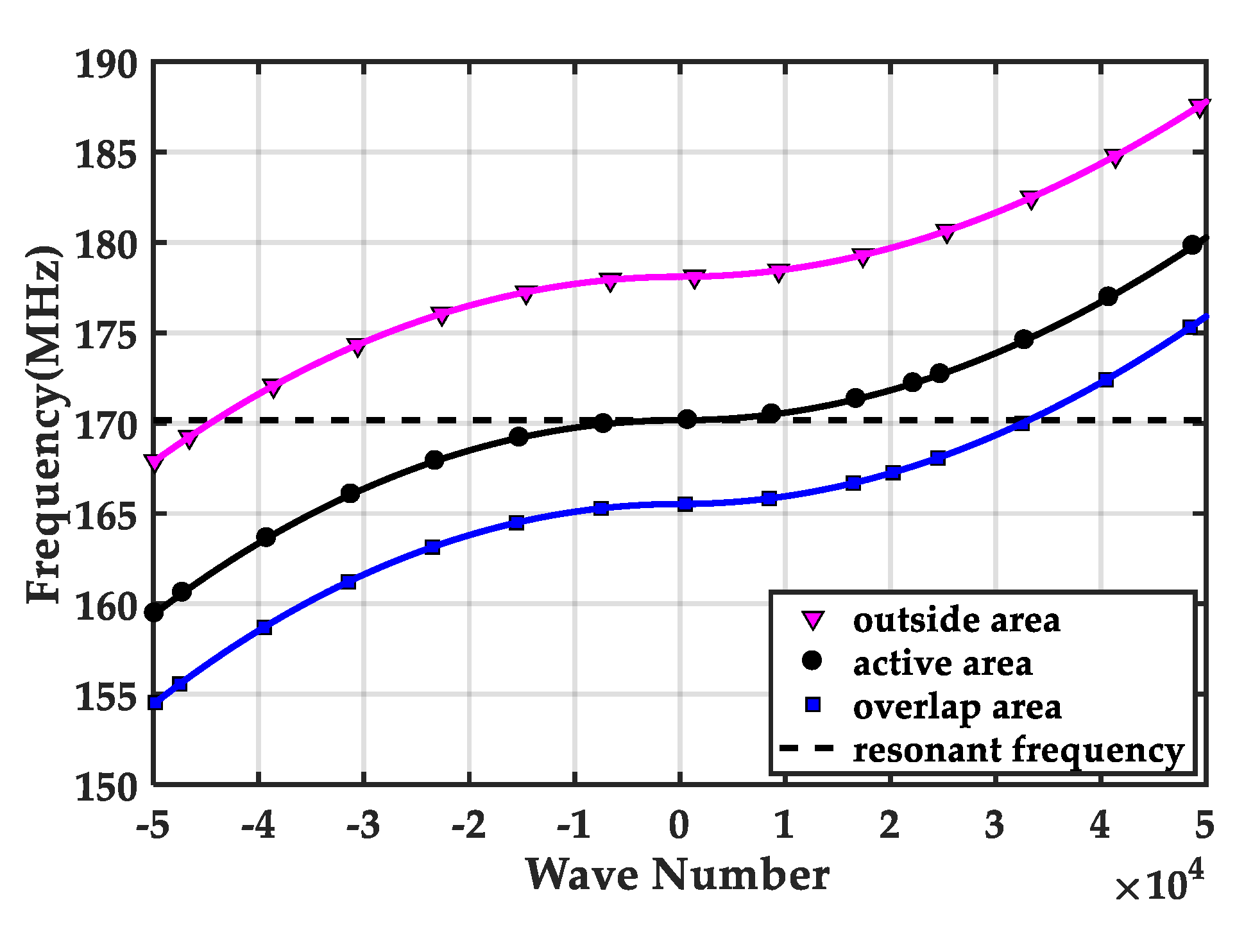
Lastly, we study the mechanism to achieve a uniform mass sensitivity distribution in the active area from the view of dispersion curve. The dispersion characteristics of the thickness extensional wave near the cut-off frequency for the outside, active, and overlap regions are separately obtained according to Equation (13), as shown in Figure 6. For a pure real ξ, the plate wave can propagate along the in-plane direction. For a pure imaginary ξ, the wave decays exponentially. For a zero wave number, the amplitude of the wave is independent on the in-plane coordinate, resulting in a platform [23]. Therefore, for a fixed resonant frequency, the corresponding mode shape depends on the wave numbers in the outside, overlap, and active area. If the vibration frequency of the whole FBAR mass sensor is equal to the cut-off frequency of the active region, a nearly uniform mass sensitivity platform in the active region can be achieved.
5. Conclusions
In this paper, a ZnO FBAR sensor with its top surface covered by a circular frame-like electrode is proposed to achieve a uniform mass sensitivity distribution in its active area. The two-dimensional scalar equations by Tiersten and Steven were employed to study this frame-like electrode FBAR mass sensor, and the resonant frequency and corresponding vibration mode were obtained. The effect of the electrode dimensions and the mass inertia were also investigated in detail to achieve a more uniform mass sensitivity distribution. Numerical results show that compared with the reported ring electrode FBAR, our frame-like electrode FBAR can achieve a maximum optimization rate of 97.90% for the uniformity under the same structural parameters, which is much higher than the optimization ratio of 77.63% obtained by the reported double-ring electrode design. The mechanism to achieve the mass sensitivity platform in the active area is clearly stated by analyzing the dispersion curve and proved by the mode shapes under different structural sizes. These results are crucial for the optimization and design of the high-performance FBAR mass sensors.
Author Contributions
X.Z., data curation, formal analysis, investigation, writing—original draft; Z.Z., investigation, methodology, validation, writing—review and editing; B.W., formal analysis, investigation, software, supervision; Z.Q., conceptualization, methodology, project administration, writing—original draft; T.M., investigation, writing—review and editing. All authors have read and agreed to the published version of the manuscript.
Funding
This research was funded by the National Natural Science Foundation of China [Grant numbers 11502108, 1611530686], the State Key Laboratory of Mechanics and Control of Mechanical Structures at NUAA [MCMS-E-0520K02], and the Key Laboratory of Impact and Safety Engineering, Ministry of Education at Ningbo University[CJ201904].
Acknowledgments
The authors gratefully acknowledge the support from the State Key Laboratory of Mechanics and Control of Mechanical Structures at NUAA, and the Key Laboratory of Impact and Safety Engineering, Ministry of Education at Ningbo University.
Conflicts of Interest
The authors declare no conflict of interest.
References
- Sauerbrey, G. Use of vibrating quartz for thin film weighing and microweighing. Z. Phys. 1959, 155, 206–222. (In German) [Google Scholar] [CrossRef]
- King, W.H. Piezoelectric Sorption Detector. Anal. Chem. 1964, 36, 1735–1739. [Google Scholar] [CrossRef]
- Zhou, R.N.; Menon, A.; Jose, F. A chemical sensor with improved selectivity using a modified-electrode QCR. In Proceedings of the IEEE International Frequency Control Symposium, Orlando, FL, USA, 30 May 1997; pp. 56–63. [Google Scholar]
- Wang, Z.Y.; Zhu, H.Z.; Dong, Y.G.; Feng, G.P. Development of a High-Resolution Quartz Resonator Force and Weight Sensor with Increased Reliability. IEEE/ASME Trans. Mechatron. 2004, 9, 399–406. [Google Scholar] [CrossRef]
- Murozaki, Y.; Arai, F. Wide Range Load Sensor Using Quartz Crystal Resonator for Detection of Biological Signals. IEEE Sens. J. 2015, 15, 1913–1919. [Google Scholar] [CrossRef]
- Lakin, K.M. A review of thin-film resonator technology. IEEE Micro. Mag. 2003, 4, 61–67. [Google Scholar] [CrossRef]
- Zhang, H.; Kim, E.S. Micromachined acoustic resonant mass sensor. J. Microelectromechanical Syst. 2005, 14, 699–706. [Google Scholar] [CrossRef]
- Lobl, H.P.; Klee, M.; Milsom, R.; Dekker, R.; Metzmacher, C.; Brand, W.; Lok, P. Materials for bulk acoustic wave (BAW) resonators and filters. J. Euro. Cera. Soc. 2001, 21, 2633–2640. [Google Scholar] [CrossRef]
- Zhang, Y.; Luo, J.K.; Flewitt, A.J.; Cai, Z.Q.; Zhao, X.B. Film bulk acoustic resonators (FBARs) as biosensors: A review. Biosens. Bioelectron. 2018, 116, 1–15. [Google Scholar] [CrossRef] [PubMed]
- Josse, F.; Lee, Y.; Martin, S.J.; Cernosek, R.W. Analysis of the Radial Dependence of Mass Sensitivity for Modified-Electrode Quartz Crystal Resonators. Anal. Chem. 1998, 70, 237–247. [Google Scholar] [CrossRef]
- Gao, J.Y.; Huang, X.H.; Wang, Y. The modified design of ring electrode quartz crystal resonator for uniform mass sensitivity distribution. IEEE Trans. Ultrason. Ferroelectr. Freq. Control 2013, 60, 2031–2034. [Google Scholar] [PubMed]
- Huang, X.H.; Pan, W.; Hu, J.G.; Bai, Q.S. The Exploration and Confirmation of the Maximum Mass Sensitivity of Quartz Crystal Microbalance. IEEE Trans. Ultrason. Ferroelectr. Freq. Control 2018, 65, 1888–1892. [Google Scholar] [CrossRef] [PubMed]
- Richardson, A.; Bhethanabotla, V.R.; Smith, A.L.; Josse, F. Patterned Electrodes for Thickness Shear Mode Quartz Resonators to Achieve Uniform Mass Sensitivity Distribution. IEEE Sens. J. 2010, 19, 1772–1777. [Google Scholar]
- Steen, C.V.D.; Boersma, F.; Ballegooyen, E.C.V. The influence of mass loading outside the electrode area on the resonant frequencies of a quartz-crystal microbalance. J. Appl. Phys. 1977, 48, 3201–3205. [Google Scholar] [CrossRef]
- Vig, J.R.; Ballato, A. Comments about the Effects of Nonuniform Mass Loading on a Quartz Crystal Microbalance. IEEE Trans. Ultrason. Ferroelectr. Freq. Control 1998, 45, 1123–1124. [Google Scholar] [CrossRef] [PubMed]
- Zhao, Z.N.; Qian, Z.H.; Wang, B.; Yang, J.S. Energy trapping of thickness-extensional modes in thin film bulk acoustic wave resonators. J. Mechan. Sci. Technol. 2015, 29, 2767–2773. [Google Scholar] [CrossRef]
- Liu, J.; Ma, T.F.; Du, J.K.; Wang, J.; Yang, J.S. An analysis of an unbounded thin film bulk acoustic wave piezoelectric resonator with a circular driving electrode. Int. J. Appl. Electromagn. Mech. 2018, 56, 11–19. [Google Scholar] [CrossRef]
- Shi, J.J.; Fan, C.Y.; Zhao, M.H.; Yang, J.S. Thickness-shear vibration characteristics of an AT-cut quartz resonator with rectangular ring electrodes. Int. J. Appl. Electromagn. Mech. 2016, 51, 1–10. [Google Scholar] [CrossRef]
- Zhao, Z.N.; Qian, Z.H.; Wang, B. Vibration optimization of ZnO thin film bulk acoustic resonator with ring electrodes. AIP Adv. 2016, 6, 1–12. [Google Scholar] [CrossRef] [Green Version]
- Liu, J.; Du, J.K.; Wang, J.; Yang, J.S. Thin film bulk acoustic wave piezoelectric resonators with circular ring driving electrodes for mass sensing. Integ. Ferroelectr. 2019, 192, 57–66. [Google Scholar] [CrossRef]
- Tiersten, H.F.; Stevens, D.S. An analysis of thickness-extensional trapped energy resonant device structures with rectangular electrodes in the piezoelectric thin film on silicon configuration. J. Appl. Phys. 1983, 54, 5893–5910. [Google Scholar] [CrossRef]
- Auld, B.A. Acoustic Fields and Waves in Solids; John Willey and Sons: New York, NY, USA, 1973; pp. 357–382. [Google Scholar]
- Kaitila, J. Review of wave propagation in BAW thin film devices progress and prospects. In Proceedings of the IEEE Ultrasonics Symposium, New York, NY, USA, 28–31 October 2007; pp. 120–129. [Google Scholar]
Figure 1.
The schematic of a ZnO film bulk acoustic resonator (FBAR) with a circular frame-like driving electrode. It consists of a driving electrode, a ZnO film, a ground electrode, and a Si substrate, where h indicates the thickness of each region and r represents the electrode size.
Figure 1.
The schematic of a ZnO film bulk acoustic resonator (FBAR) with a circular frame-like driving electrode. It consists of a driving electrode, a ZnO film, a ground electrode, and a Si substrate, where h indicates the thickness of each region and r represents the electrode size.

Figure 2.
2D top view of the fundamental thickness-extensional (TE) mode in the normal circular electrode (energy-trapped) FBAR sensor (a), the ring electrode FBAR sensor (b), and the frame-like electrode FBAR sensor (c). Normalized mass sensitivity distributions of these three cases can be seen in (d).

Figure 3.
Comparison of the frame-like electrode FBAR (a) and the ring electrode FBAR (b) [20] for different , when is fixed as and is equal to 0.04. With the decreasing of , the mass sensitivity distributions in the active region for the frame-like electrode become more uniform, but the distributions for the ring electrode are still concave.

Figure 4.
Comparison between the frame-like electrode FBAR (a) and the ring electrode FBAR (b) [20] for different , when is fixed as 30 and is equal to 0.04. With the increasing of , more uniform mass sensitivity distributions are observed for the frame-like electrode. However, it is hard for the ring electrode to achieve uniform distributions.

Figure 5.
Effects of the mass ratio of the overlap electrode to ZnO piezoelectric thin film on the mass sensitivity distributions in the frame-like electrode FBAR sensor, when is fixed as 30 and is fixed as 60. With the increasing of , the shape of the distributions change to the concave from convex. The uniform distributions in the active region are obtained for , indicating that the uniform mass sensitivity distributions can be successfully achieved by selecting proper mass ratio through the novel frame-like electrode design.

Figure 6.
Schematic of the dispersion curve of the thickness extensional (TE) wave modes in the active, overlap, and outside areas.
Figure 6.
Schematic of the dispersion curve of the thickness extensional (TE) wave modes in the active, overlap, and outside areas.


Table 1.
The comparison on the uniformity of mass sensitivity of the frame-like electrode FBAR sensor for different electrode sizes, with .
Table 1.
The comparison on the uniformity of mass sensitivity of the frame-like electrode FBAR sensor for different electrode sizes, with .
| r1(μm) | r2(μm) | f (MHz) | fa (MHz) | |f−fa| (MHz) | ΔF | ΔR [20] | (%) |
|---|---|---|---|---|---|---|---|
| 20 | 60 | 170.2664 | 170.1609 | 0.1055 | 0.0051 | 0.2430 | 97.90 |
| 30 | 60 | 171.0949 | 170.1609 | 0.9340 | 0.0974 | 0.3641 | 73.25 |
| 40 | 60 | 172.0308 | 170.1609 | 1.8699 | 0.3154 | 0.4022 | 21.58 |
| 30 | 50 | 172.5879 | 170.1609 | 2.4270 | 0.2392 | 0.2678 | 10.68 |
| 30 | 60 | 171.0949 | 170.1609 | 0.9340 | 0.0974 | 0.3641 | 73.25 |
| 30 | 70 | 169.9863 | 170.1609 | 0.1746 | 0.0186 | 0.3965 | 95.31 |
f is the resonant frequency of the FBAR mass sensor. fa is the cut-off frequency in the active region of the frame-like FBAR. |f−fa| is the deviation between the resonant frequency f of the FBAR sensor and the cut-off frequency fa. Δ is the mass sensitivity amplitude deviation between the highest peak and the lowest valley in the active area of FBAR, in which the subscripts F and R stand for the frame-like electrode FBAR and the ring electrode FBAR, respectively. is the optimization rate on the uniformity of mass sensitivity distribution in the frame-like electrode FBAR compared with the ring electrode FBAR.
Table 2.
The comparison on the uniformity of mass sensitivity of the frame-like electrode FBAR sensor for different mass ratios , with and .
Table 2.
The comparison on the uniformity of mass sensitivity of the frame-like electrode FBAR sensor for different mass ratios , with and .
| f (MHz) | fa (MHz) | |f − fa| (MHz) | ΔF | |
|---|---|---|---|---|
| 0.01 | 173.4852 | 170.1609 | 3.3243 | 0.3166 |
| 0.04 | 171.0949 | 170.1609 | 0.9340 | 0.0974 |
| 0.05 | 170.2402 | 170.1609 | 0.0811 | 0.0087 |
| 0.06 | 169.3639 | 170.1609 | 0.7970 | 0.0811 |
© 2020 by the authors. Licensee MDPI, Basel, Switzerland. This article is an open access article distributed under the terms and conditions of the Creative Commons Attribution (CC BY) license (http://creativecommons.org/licenses/by/4.0/).
Share and Cite
MDPI and ACS Style
Zhao, X.; Zhao, Z.; Wang, B.; Qian, Z.; Ma, T. The Design of a Frame-Like ZnO FBAR Sensor for Achieving Uniform Mass Sensitivity Distributions. Sensors 2020, 20, 2408. https://doi.org/10.3390/s20082408
AMA Style
Zhao X, Zhao Z, Wang B, Qian Z, Ma T. The Design of a Frame-Like ZnO FBAR Sensor for Achieving Uniform Mass Sensitivity Distributions. Sensors. 2020; 20(8):2408. https://doi.org/10.3390/s20082408
Chicago/Turabian StyleZhao, Xueli, Zinan Zhao, Bin Wang, Zhenghua Qian, and Tingfeng Ma. 2020. "The Design of a Frame-Like ZnO FBAR Sensor for Achieving Uniform Mass Sensitivity Distributions" Sensors 20, no. 8: 2408. https://doi.org/10.3390/s20082408
Note that from the first issue of 2016, this journal uses article numbers instead of page numbers. See further details here.