Article

High Sensitivity Refractive Index Sensor Based on Dual-Core Photonic Crystal Fiber with Hexagonal Lattice

College of Information Science and Engineering, Northeastern University, Shenyang 110819, China
*
Author to whom correspondence should be addressed.
Sensors 2016, 16(10), 1655; https://doi.org/10.3390/s16101655
Submission received: 19 July 2016 / Revised: 12 September 2016 / Accepted: 29 September 2016 / Published: 8 October 2016
(This article belongs to the Section Physical Sensors)

Abstract

:
A refractive index sensor based on dual-core photonic crystal fiber (PCF) with hexagonal lattice is proposed. The effects of geometrical parameters of the PCF on performances of the sensor are investigated by using the finite element method (FEM). Two fiber cores are separated by two air holes filled with the analyte whose refractive index is in the range of 1.33–1.41. Numerical simulation results show that the highest sensitivity can be up to 22,983 nm/RIU(refractive index unit) when the analyte refractive index is 1.41. The lowest sensitivity can reach to 21,679 nm/RIU when the analyte refractive index is 1.33. The sensor we proposed has significant advantages in the field of biomolecule detection as it provides a wide-range of detection with high sensitivity.

1. Introduction

Photonic crystal fiber, which is also called micro-structured optical fiber, has many advantages such as endless single mode, ultra low loss, high birefringence and high nonlinearity [1,2,3,4]. Due to its particular optical properties compared with conventional fibers, PCF has been applied in many optical devices such as fiber lasers, optical communications and fiber sensors [5,6,7]. The refractive index sensor based on PCF has attracted considerable attention to the potential in the remote real-time detection recently. With the improvement of fabrication technology and sensing technique on detecting the refractive index, PCF sensors have widely used in many aspects of the chemical and biological detection industry [8,9,10].
Most of PCF sensors are based on surface plasmon resonance (SPR), photonic bandgap properties of the PCF or resonant coupling. In 2009, Shi provided a refractive index sensor based on photonic bandgap fiber with long period grating and demonstrated a sensitivity of 17,900 nm/RIU [11]. In 2012, Tian proposed PCF-based SPR sensors and its numerical results showed that the refractive index sensitivity of the sensor is 7300 nm/RIU [12]. In 2013, Xiao investigated a refractive index sensor based on the resonant coupling mechanism and its numerical results revealed that the sensitivity of the sensor could reach to 17,250 nm/RIU [13].
From the sensors mentioned above, only one-core PCF was used. However, due to the design flexibility and the matured stack-and-draw fabrication technology, multi-core PCFs including dual-core PCFs have showed excellent performances in special applications such as polarization splitter, polarization filter and refractive index sensors [14,15,16]. In 2012, Shuai numerically characterized a multi-core PCF-based sensor which average sensitivity is 2929.39 nm/RIU in the sensing range of 1.33–1.42 [17]. We know that the refractive index detection can be implemented by resonant coupling in dual-core PCF. The detection sensitivity of the sensor can be effectively improved by filling the analytes into the central air holes [18]. Moreover, both wide-range detection and high sensitivity can be achieved by using the exponential dependence of inter-core coupling on analyte refractive index [19].
Refractive index sensors have attracted a lot of attention in the field of biomolecule detection as they provide a wide-range of detection with high sensitivity. Rindorf demonstrated the long-period gratings in PCF can be used for biological sesnsing by filling the biological molecule into the air holes and measured the thicknesses of a monolayer of poly-L-lysine and double-stranded DNA [20]. Jensen demonstrated selective detection of α-streptavidin or α-CRP antibodies in microstructured polymer optical fibers by a sensor layer of complementary biomolecules immobilized inside the air holes [21].
In this paper, we design a refractive index sensor based on dual-core photonic crystal fiber with a hexagonal air-hole lattice structure. For the dual-core PCF sensor we proposed, the sensitivity is calculated according to the energy coupling between two cores. The sensitivity of the sensor we designed is much higher. The sensitivity of the sensor we proposed can reach to 21,679–22,983 nm/RIU with a dynamic refractive index ranging of 1.33–1.41. Besides, we only filled analytes into the air holes to detect the refractive index of the analytes. It is much easier to manufacture, which is a better candidate for refractive index sensor devices.

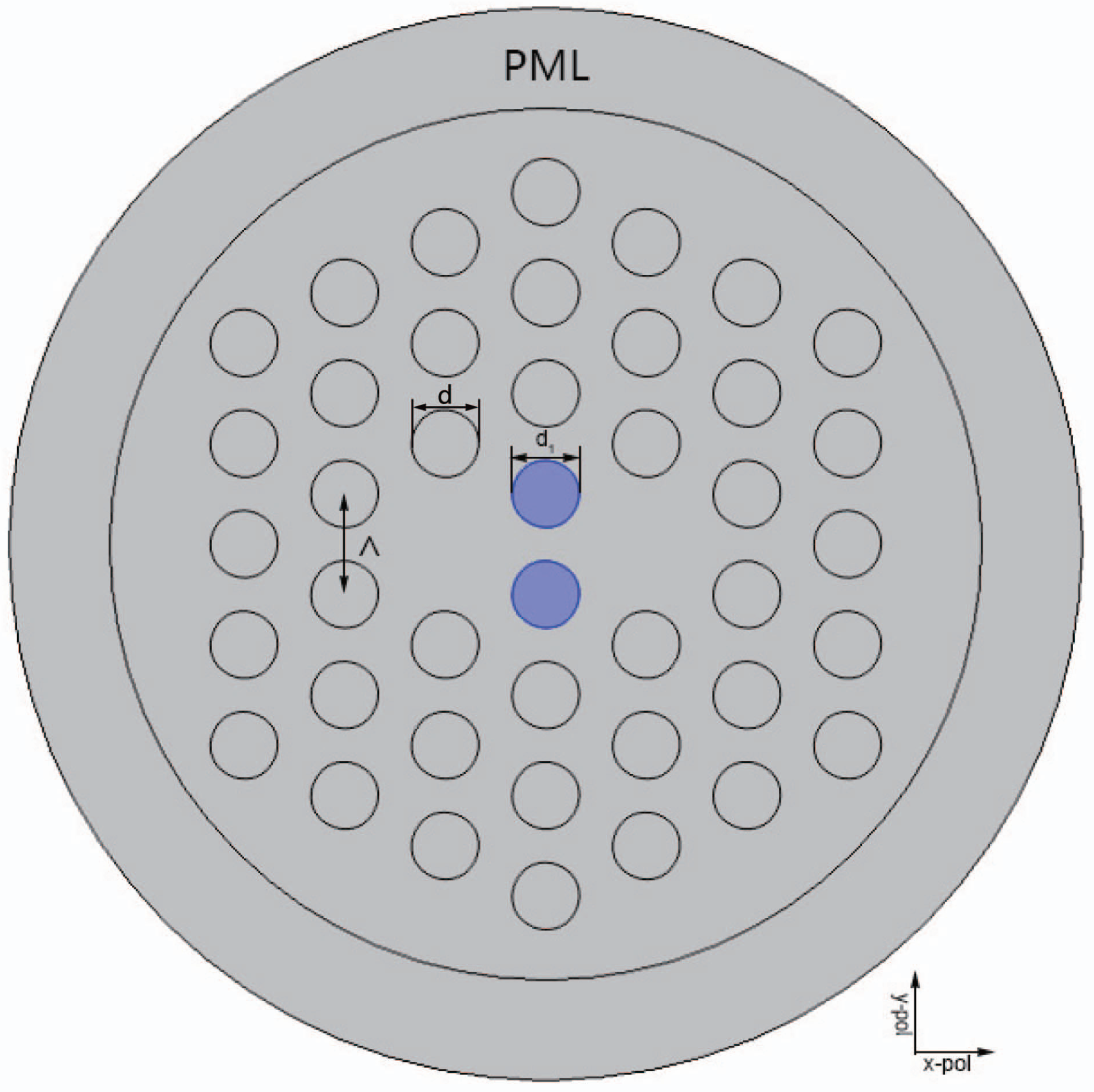
2. The Structure and Theoretical Analysis

The cross section of the proposed sensor with hexagonal air-hole lattice is shown in Figure 1. The properties of the proposed sensor have been analyzed with the FEM by using the COMSOL Multiphysics software [22]. A perfectly matched layer (PML) and a scattering boundary condition are used to decrease the energy loss [23]. The analyte is filled into two air holes located in the center to increase the area of the analyte which can greatly improve the sensitivity of the sensor. The refractive index of anlyate is n a .
All the diameters of the air holes are d = d 1 = 2 μ m and the pitch of the adjacent air holes is Λ = 3 μ m, as shown in Figure 1. The impact on the properties of the proposed sensor by changing the d 1 and Λ will be discussed later.
The background material is fused silica whose material dispersion can be obtained from the Sellmeier formula [24]:
n 2 ( ω ) = 1 + j = 1 3 B j ω j 2 ω j 2 - ω 2
where B 1 = 0 . 6961663 , B 2 = 0 . 4079426 , B 3 = 0 . 8974794 , λ 1 = 0 . 0684043 μ m, λ 2 = 0 . 1162414 μ m, λ 3 = 9 . 896161 μ m, λ j = 2 π c / ω j and c is the speed of light in vacuum.
Regarding to the fabrication, the refractive index sensor we proposed is easier to manufacture compared with the complex structures mentioned in the previous literatures [25,26,27]. With the development of infiltration technique, the samples filled into the PCF have been illustrated both experimentally and theoretically [28,29]. It is possible to fabricate the proposed refractive index sensor in the practical production.
The two fiber cores of the PCF are formed by eliminating two central air holes in the horizontal direction. The anylate is filled into two central air holes in the vertical direction for detection. According to the coupling theory, the dual-core PCF has four supermodes in the x-polarization (x-even and x-odd) and the y-polarization (y-even and y-odd). Figure 2 shows the electric field distributions of the proposed sensor.
The coupling length of the dual-core PCF indicates the periodic variation of energy between the two cores, which can be defined by the formula [30]:
L i = π β e i - β o i = λ 2 ( n e i - n o i ) , i = x , y
where β e i and β o i are the propagation constants of i-polarized even and odd super modes, n e i and n o i are the effective refractive indexes of i-polarized even and odd super modes respectively.
The effective refractive index of the dual-core PCF was simulated, as shown in Figure 3a. With the increasing of wavelength, the effective refractive index of four supermodes decreases. The effective refractive index in y-polarization decrease faster than that in x-polarization. The variations of Δ n e o = | n e - n o | with wavelength in x-polarization and y-polarization were simulated, as shown in Figure 3b. With the increasing of wavelength, the index difference ( Δ n e o ) increases and the index difference in x-polarization is larger than that in y-polarization.
Figure 4 shows the variation of coupling length with wavelength in x-polarization and y-polarization when the analyte refractive index is n a = 1 . 33 . It is obvious that the coupling length decreases with the increasing of wavelength in x-polarization and y-polarization. Moreover, the coupling length in y-polarization is larger than that in x-polarization.

3. Results and Discussion

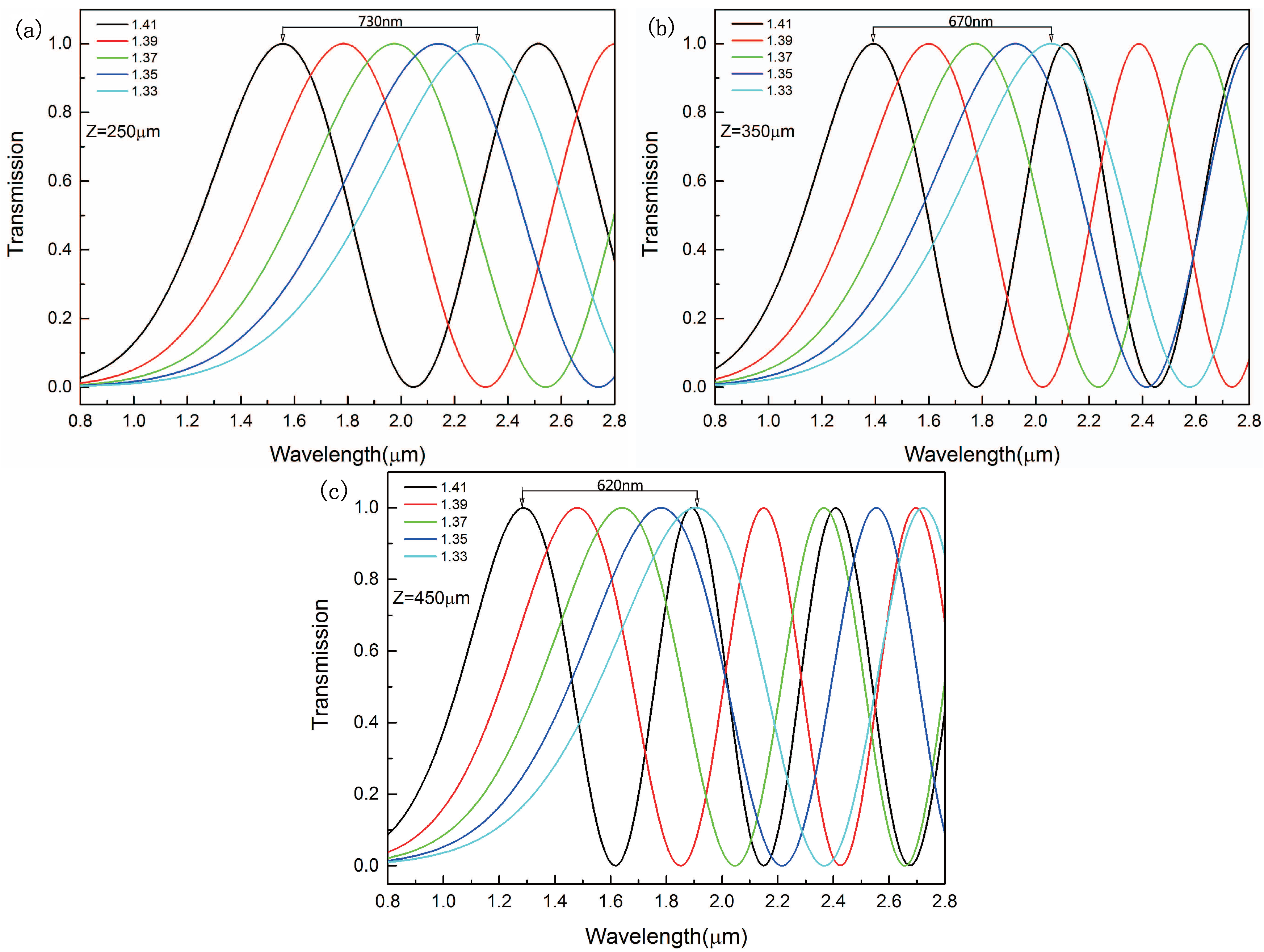
3.1. The Determine of the Transmission Length for the Refractive Index Sensor

The transmission curves for x-polarized light with different transmission lengths were simulated, as shown in Figure 5. All of the wavelength peaks experiences a blue shift when the refractive index increases from 1.33 to 1.41. As we can see from Figure 5, when the transmission length is 250 μ m, 350 μ m and 450 μ m, the distance between the peaks is 730 nm, 670 nm and 620 nm respectively. With the increasing of transmission length from 250 μ m to 450 μ m, the distance between the peaks slightly decreases. It represents that the sensitivity of the sensor slightly decreases when the transmission length increases from 250 μ m to 450 μ m. We can also see from Figure 5c that the second peak in n a = 1 . 41 intersects with the peak in n a = 1 . 33 when the fiber length is 450 μ m. It is difficult to detect the refractive index when two peaks intersect in different refractive indices. In order to separate the two peaks to eliminate the influence, we choose that the transmission length is 250 μ m which can avoid intersection.

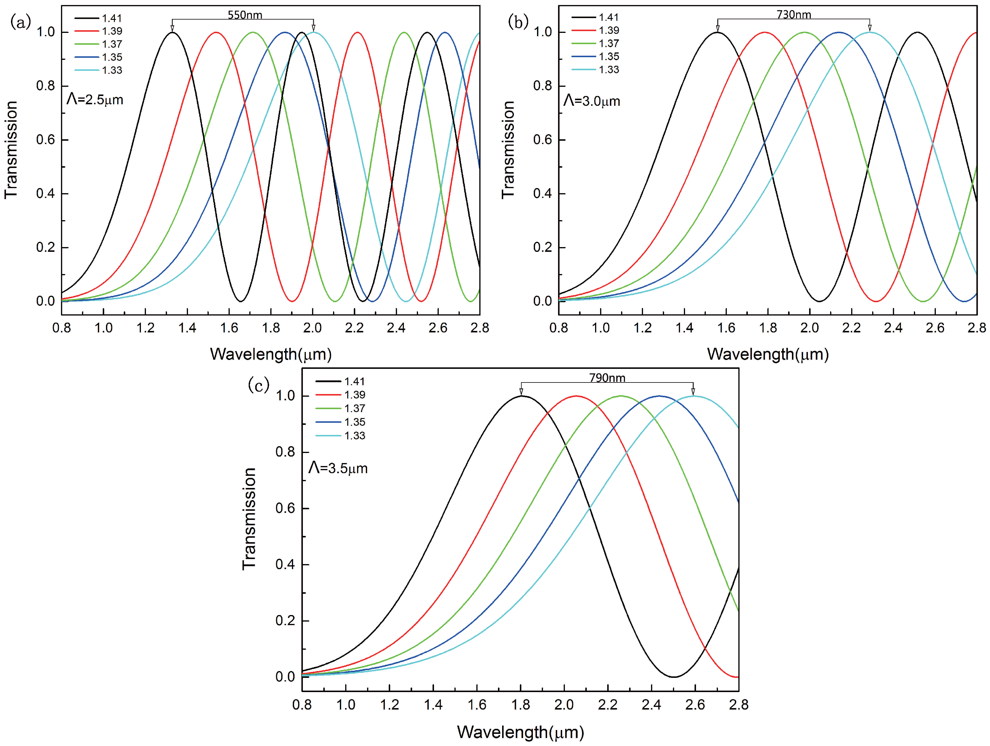
3.2. The Effect of the Adjacent Air Holes Pitches on Sensitivity

In this section, we discuss the impact of the pitch of the adjacent air holes on sensitivity. The transmission length of the sensor is 250 μ m. Figure 6 shows the transmission curves in x-polarization when the pitch of the adjacent air holes changes from Λ = 2 . 5 μ m to Λ = 3 . 5 μ m. The wavelength peaks experience a blue shift when the refractive index of the analyte ranges from 1.33 to 1.41. With the increasing of the Λ, both the distance between the peaks and the period of transmission curves increase. The distance between the peaks increases from 550 nm to 730 nm when the pitch of the adjacent air holes changes from Λ = 2 . 5 μ m to Λ = 3 . 0 μ m. However, the distance increases only from 730 nm to 790 nm when Λ changes from 2 . 5 μ m to 3 . 0 μ m. The distance between the peaks is crucial to the sensitivity. With the increasing of the distance between the peaks, the sensitivity can be higher. However, the distance between the peaks increases slowly. The proposed sensor detects the refractive index mainly according to the wavelength peaks. Obviously, the shorter period is more beneficial to wavelength measurement and vice versa. It is not the best way to improve the sensitivity by increasing the pitch of the adjacent air holes.

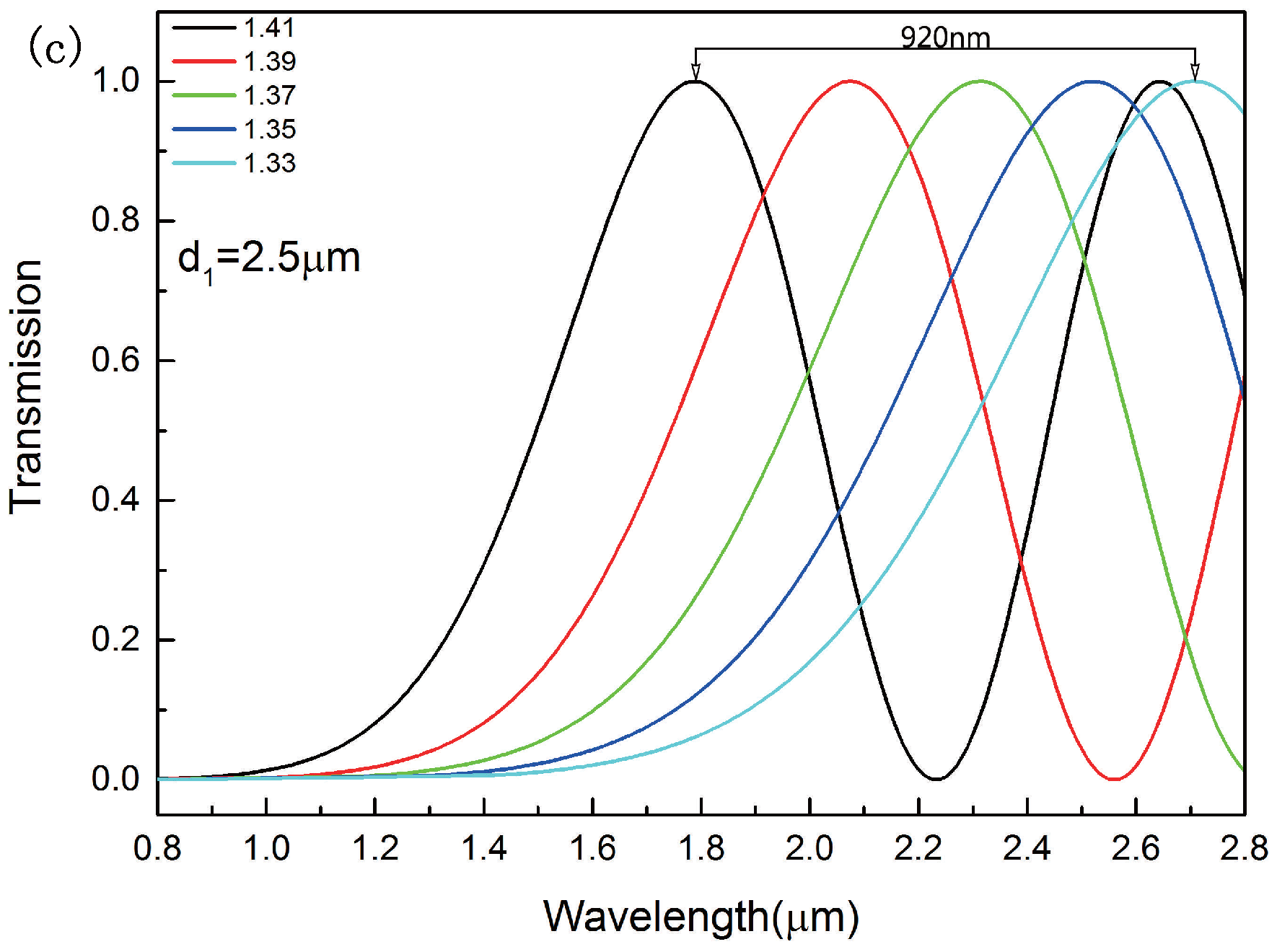
3.3. The Effect of the Size of the Analyte-Filled Air Holes on Sensitivity

The diameter of the analyte-filled air holes d 1 is a key parameter for the sensitivity of the proposed sensor. Figure 7 shows the transmission curves in x-polarization with different diameters of analyte-filled air holes. The transmission length of the sensor is also 250 μ m. All the wavelength peaks experience a red shift when the diameter of d 1 changes from 1 . 5 μ m to 2 . 5 μ m. With the increasing of d 1 , the distance between the peaks increases significantly. When the diameter of d 1 changes from 2 . 0 μ m to 2 . 5 μ m, the distance between the peaks increases from 730 nm to 920 nm. When the diameter of d 1 changes from 1 . 5 μ m to 2 . 0 μ m, the distance between the peaks increases form 480 nm to 730 nm. It means that the sensitivity of the sensor increases markedly. Furthermore, the refractive index of the analyte can be measured more accurately due to the constant period. It is the most effective way to improve the sensitivity by increasing the diameter of the analyte-filled air holes.

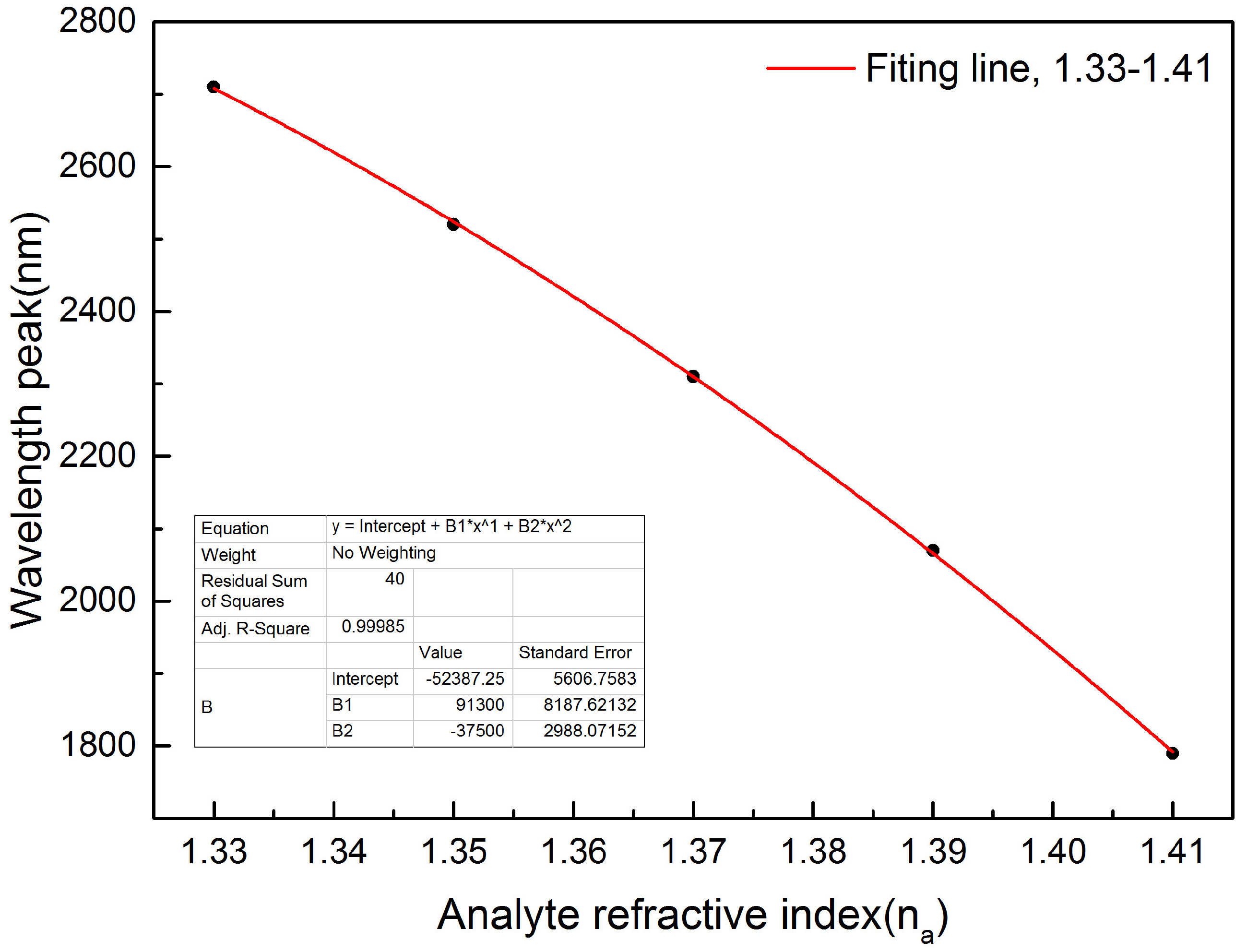
3.4. The Result of Numerical Fitting and Sensitivity Calculation

We calculate the sensitivity by using the shift of the peaks with the variation of the analyte refractive index. The refractive index sensitivity S can be written as:
S λ ( n m R I U - 1 ) = Δ λ p e a k / Δ n a
where λ p e a k is the shift of the transmission curve and Δ n a is the variation of the analyte refractive index.
Figure 8 shows the numerical fitting result. The slope of the curve stands for the sensitivity of the proposed sensor. The fitting equation and value are shown in the inset of Figure 8. Calculation result shows that the highest sensitivity of x-polarized light is 22,983 nm/RIU when the analyte refractive index is n a = 1 . 41 at the operate wavelength of 1 . 79 μ m. The lowest sensitivity of x-polarized light is 21,679 nm/RIU when the analyte refractive index is n a = 1 . 33 at the operate wavelength of 2 . 71 μ m. It is much higher than the highest sensitivity among the refractive index sensors mentioned in the previous literatures [31,32,33]. The sensor we proposed have a good prospect on sensor devices due to the high sensitivity. Moreover, we calculate the highest sensitivity of y-polarized light is 20,014 nm/RIU with the analyte refractive index is n a = 1 . 41 . The sensitivity in x-polarized light is larger than that in y-polarized light, so we adopt x-polarized light as the analyze mode.
If the instrumental peak-wavelength resolution is assumed to be Δ λ m i n = 0 . 1 nm, the refractive index resolution of the corresponding sensor can be obtained as:
R = Δ n a Δ λ m i n / Δ λ p e a k
where Δ n a = 0.02, Δ λ p e a k = 190 nm, 210 nm, 240 nm and 280 nm respectively when refractive index changes from 1.33 to 1.41. According to the parameters mentioned above, the refractive index resolution we calculate is 1.05 × 10 - 5 RIU, 9.52 × 10 - 6 RIU, 8.33 × 10 - 6 RIU and 7.14 × 10 - 6 RIU respectively.
The refractive index sensor we proposed can achieve quantitative detection by detecting small change in the analyte refractive index. We can detect the change of the information of the biological molecule reaction by measuring the wavelength. The sensor will have broad application in many fields such as pathogens, toxins, drug residues, vitamins, antibodies, proteins and parasites as it can provide high sensitivity, label-free and wide-range detection.

4. Conclusions

A refractive index sensor based on dual-core photonic crystal fiber with hexagonal lattice has been proposed. Numerical analysis of the proposed structure is carried out with FEM. The properties of the refractive index sensor are discussed and numerical results show that the optimal sensitivity of the structure can be up to 22,983 nm/RIU when the refractive index of the analyte is n a = 1 . 41 . The lowest sensitivity can reach to 21,679 nm/RIU when the refractive index of the analyte is n a = 1 . 33 . Moreover, good resolution of 10 - 6 RIU is achieved for the proposed structure. Both wide-range and high sensitivity making it possible to achieve real-time, fast and convenient detection.

Acknowledgments

This work was supported by Natural Science Foundation of Liaoning Province, China (2014020020), National Natural Science Foundation of China under Grant No. 61574143 and 51607029, Fundamental Research Funds for the Central Universities under Grants No. N130404001, N150403003 and N150404003, and the Project-sponsored by SRF for ROCS, SEM(47-6).

Author Contributions

H.W. and X.Y. conceived and designed the structure; H.W. and S.L. performed the simulations; H.W. and G.A. analyzed the data; H.W. and X.Z. contributed analysis tools; H.W. and X.Y. wrote the paper.

Conflicts of Interest

The authors declare no conflict of interest.

References

  1. Birks, T.A.; Knight, J.C.; Russell, P.S.J. Endlessly single-mode photonic crystal fiber. Opt. Lett. 1997, 22, 961–963. [Google Scholar] [CrossRef] [PubMed]
  2. Roberts, P.; Couny, F.; Sabert, H.; Mangan, B.; Williams, D.; Farr, L.; Mason, M.; Tomlinson, A.; Birks, T.; Knight, J.; et al. Ultimate low loss of hollow-core photonic crystal fibres. Opt. Express 2005, 13, 236–244. [Google Scholar] [CrossRef] [PubMed]
  3. Yue, Y.; Kai, G.; Wang, Z.; Sun, T.; Jin, L.; Lu, Y.; Zhang, C.; Liu, J.; Li, Y.; Liu, Y.; et al. Highly birefringent elliptical-hole photonic crystal fiber with squeezed hexagonal lattice. Opt. Lett. 2007, 32, 469–471. [Google Scholar] [CrossRef] [PubMed]
  4. Liao, M.; Yan, X.; Qin, G.; Chaudhari, C.; Suzuki, T.; Ohishi, Y. A highly non-linear tellurite microstructure fiber with multi-ring holes for supercontinuum generation. Opt. Express 2009, 17, 15481–15490. [Google Scholar] [CrossRef] [PubMed]
  5. Hundertmark, H.; Rammler, S.; Wilken, T.; Holzwarth, R.; Hänsch, T.W.; Russell, P.S. Octave-spanning supercontinuum generated in SF6-glass PCF by a 1060 nm mode-locked fibre laser delivering 20 pJ per pulse. Opt. Express 2009, 17, 1919–1924. [Google Scholar] [CrossRef] [PubMed]
  6. Kurokawa, K.; Tajima, K.; Nakajima, K. 10-GHz 0.5-ps Pulse Generation in 1000-nm Band in PCF for High-Speed Optical Communication. J. Lightwave Technol. 2007, 25, 75–78. [Google Scholar] [CrossRef]
  7. Lu, Y.; Hao, C.J.; Wu, B.Q.; Musideke, M.; Duan, L.C.; Wen, W.Q.; Yao, J.Q. Surface plasmon resonance sensor based on polymer photonic crystal fibers with metal nanolayers. Sensors 2013, 13, 956–965. [Google Scholar] [CrossRef] [PubMed]
  8. Wang, J.J.; Chen, L.; Kwan, S.; Liu, F.; Deng, X. Resonant grating filters as refractive index sensors for chemical and biological detections. J. Vac. Sci. Technol. B 2005, 23, 3006–3010. [Google Scholar] [CrossRef]
  9. Qazi, H.H.; Mohammad, A.B.B.; Akram, M. Recent progress in optical chemical sensors. Sensors 2012, 12, 16522–16556. [Google Scholar] [CrossRef] [PubMed]
  10. Adhikari, B.R.; Govindhan, M.; Chen, A. Carbon nanomaterials based electrochemical sensors/biosensors for the sensitive detection of pharmaceutical and biological compounds. Sensors 2015, 15, 22490–22508. [Google Scholar] [CrossRef] [PubMed]
  11. Shi, Q.; Kuhlmey, B.T. Optimization of photonic bandgap fiber long period grating refractive-index sensors. Opt. Commun. 2009, 282, 4723–4728. [Google Scholar] [CrossRef]
  12. Tian, M.; Lu, P.; Chen, L.; Lv, C.; Liu, D. All-solid D-shaped photonic fiber sensor based on surface plasmon resonance. Opt. Commun. 2012, 285, 1550–1554. [Google Scholar] [CrossRef]
  13. Xiao, Y.Y.; Wang, H.W. Refractive Index Sensors Based Resonant Coupling in Solid-Core Photonic Band-Gap Fibers. Adv. Mater. Res. 2013, 753–755, 2103–2106. [Google Scholar] [CrossRef]
  14. Chen, H.; Cheng, S.L.T. Polarization splitter based on three-core photonic crystal fiber with rectangle lattice. J. Mod. Opt. 2014, 61, 1696–1701. [Google Scholar] [CrossRef]
  15. Jiang, H.; Wang, E.; Xie, K.; Hu, Z. Dual-Core Photonic Crystal Fiber for Use in Fiber Filters. IEEE Photonics J. 2016, 8. [Google Scholar] [CrossRef]
  16. Sun, B.; Chen, M.Y.; Zhang, Y.K.; Yang, J.C.; Yao, J.Q.; Cui, H.X. Microstructured-core photonic-crystal fiber for ultra-sensitive refractive index sensing. Opt. Express 2011, 19, 4091–4100. [Google Scholar] [CrossRef] [PubMed]
  17. Shuai, B.; Xia, L.; Zhang, Y.; Liu, D. A multi-core holey fiber based plasmonic sensor with large detection range and high linearity. Opt. Express 2012, 20, 5974–5986. [Google Scholar] [CrossRef] [PubMed]
  18. Wu, D.K.; Kuhlmey, B.T.; Eggleton, B.J. Ultrasensitive photonic crystal fiber refractive index sensor. Opt. Lett. 2009, 34, 322–324. [Google Scholar] [CrossRef] [PubMed]
  19. Town, G.E.; Yuan, W.; Mccosker, R.; Bang, O. Microstructured optical fiber refractive index sensor. Opt. Lett. 2010, 35, 856–858. [Google Scholar] [CrossRef] [PubMed]
  20. Rindorf, L.; Jensen, J.B.; Dufva, M.; Pedersen, L.H.; Høiby, P.E.; Bang, O. Photonic crystal fiber long-period gratings for biochemical sensing. Opt. Express 2006, 14, 8224–8231. [Google Scholar] [CrossRef] [PubMed]
  21. Jensen, J.; Hoiby, P.; Emiliyanov, G.; Bang, O.; Pedersen, L.; Bjarklev, A. Selective detection of antibodies in microstructured polymer optical fibers. Opt. Express 2005, 13, 5883–5889. [Google Scholar] [CrossRef] [PubMed]
  22. Miyashita, K.; Kuroda, S.; Ubukata, T.; Ozawa, T.; Kubota, H. Full-Vector Analysis of Photonic Crystal Fibers Using the Finite Element Method (Special Issue on Optical Fibers and Devices). IEICE Trans. Electron. 2002, 85, 881–888. [Google Scholar]
  23. Lee, H.W.; Schmidt, M.A.; Tyagi, H.K.; Sempere, L.P.; Russell, P.S.J. Polarization-dependent coupling to plasmon modes on submicron gold wire in photonic crystal fiber. Appl. Phys. Lett. 2008, 93, 111102. [Google Scholar] [CrossRef]
  24. Agrawal, G.P. Nonlinear Fiber Optics; Academic Press: Cambridge, MA, USA, 1989. [Google Scholar]
  25. Ademgil, H.; Haxha, S. PCF Based Sensor with High Sensitivity, High Birefringence and Low Confinement Losses for Liquid Analyte Sensing Applications. Sensors 2015, 15, 31833–31842. [Google Scholar] [CrossRef] [PubMed]
  26. Guan, C.; Yuan, L.; Shi, J. Supermode analysis of multicore photonic crystal fibers. Opt. Commun. 2010, 283, 2686–2689. [Google Scholar] [CrossRef]
  27. Shuai, B.; Xia, L.; Liu, D. Coexistence of positive and negative refractive index sensitivity in the liquid-core photonic crystal fiber based plasmonic sensor. Opt. Express 2012, 20, 25858–25866. [Google Scholar] [CrossRef] [PubMed]
  28. Wang, Y.; Liao, C.R.; Wang, D.N. Femtosecond laser-assisted selective infiltration of microstructured optical fibers. Opt. Express 2010, 18, 18056–18060. [Google Scholar] [CrossRef] [PubMed]
  29. Hunger, D.; Deutsch, C.; Barbour, R.J.; Warburton, R.J.; Reichel, J. Laser micro-fabrication of concave, low-roughness features in silica. AIP Adv. 2011, 2, 943–948. [Google Scholar] [CrossRef]
  30. Wang, Z.; Taru, T.; Birks, T.; Knight, J.; Liu, Y.; Du, J. Coupling in dual-core photonic bandgap fibers: Theory and experiment. Opt. Express 2007, 15, 4795–4803. [Google Scholar] [CrossRef] [PubMed]
  31. Huang, T. Highly Sensitive SPR Sensor Based on D-shaped Photonic Crystal Fiber Coated with Indium Tin Oxide at Near-Infrared Wavelength. Plasmonics 2016, 1–6. [Google Scholar] [CrossRef]
  32. Wo, J.; Wang, G.; Cui, Y.; Sun, Q.; Liang, R.; Shum, P.P.; Liu, D. Refractive index sensor using microfiber-based Mach—Zehnder interferometer. Opt. Lett. 2012, 37, 67–69. [Google Scholar] [CrossRef] [PubMed]
  33. Lu, P.; Men, L.; Sooley, K.; Chen, Q. Tapered fiber Mach–Zehnder interferometer for simultaneous measurement of refractive index and temperature. Appl. Phys. Lett. 2009, 94, 131110. [Google Scholar] [CrossRef] [Green Version]
Figure 1. Cross-section of the proposed refractive index sensor.
Sensors 16 01655 g001
Figure 2. Electric filed distributions of the four supermodes in the PCF sensor: (a) the x-polarized odd mode (b) the x-polarized even mode (c) the y-polarized odd mode (d) the y-polarized even mode.
Sensors 16 01655 g002
Figure 3. (a) The four lines are the effective refractive index of four supermodes of the dual-core PCF when n a = 1 . 33 , d 1 = 2 μ m and Λ = 3 μ m; (b) Black and red lines are the calculated effective refractive difference of the four supermodes when n a = 1 . 33 , d 1 = 2 μ m and Λ = 3 μ m.
Sensors 16 01655 g003
Figure 4. Black and red lines are the calculated coupling length of the dual-core PCF in x-polarization and y-polarization respectively when n a = 1 . 33 , d 1 = 2 μ m and Λ = 3 μ m.
Sensors 16 01655 g004
Figure 5. Transmission curve for the refractive index of the analyte in the range of 1.33–1.41 when the transmission length is (a) Z = 250 μ m; (b) Z = 350 μ m; (c) Z = 350 μ m.
Sensors 16 01655 g005
Figure 6. Transmission curve for the refractive index of the analyte in the range of 1.33–1.41 when the pitch of the adjacent air holes is (a) Λ = 2 . 5 μ m; (b) Λ = 3 . 0 μ m; (c) Λ = 3 . 5 μ m.
Sensors 16 01655 g006
Figure 7. Transmission curve for the refractive index of the analyte in the range of 1.33–1.41 when the diameter of analyte-filled air holes is (a) d 1 = 1 . 5 μ m; (b) d 1 = 2 . 0 μ m; (c) d 1 = 2 . 5 μ m.
Sensors 16 01655 g007aSensors 16 01655 g007b
Figure 8. Numerical fitting result of function between analyte refractive index and wavelength peak when d 1 = 2 . 5 μ m and other parameters are fixed.
Sensors 16 01655 g008

