Article

A Fast Matching Method for the SAR Images with Large Viewing Angles Based on Inertial Navigation Information and Neighborhood Structure Consensus

College of Electronic and Information Engineering, Nanjing University of Aeronautics and Astronautics, Nanjing 210016, China
*
Author to whom correspondence should be addressed.
Remote Sens. 2023, 15(16), 4084; https://doi.org/10.3390/rs15164084
Submission received: 10 July 2023 / Revised: 8 August 2023 / Accepted: 14 August 2023 / Published: 19 August 2023

Abstract

:
In the field of multi-view SAR target location, the greater the difference in viewing angles, the higher the target location accuracy. However, this makes it difficult to match the same target between the SAR images with different viewing angles. The performance of traditional SAR image-matching algorithms will deteriorate or even fail to match the images correctly when the viewing angle is gradually increased. To solve this problem, a fast SAR matching method for the SAR images with large viewing angles based on inertial navigation information and neighborhood structure consensus (ININSC) is proposed in this paper. In this algorithm, the key targets are detected in the SAR images by using the maximum connected domain algorithm and the K-means clustering algorithm, and the connected domain centroid of the target is taken as a feature point. The approximate position of the key targets after the viewing angle change is found through inertial navigation information, and then accurate and fast matching is achieved by using the consensus of the neighborhood topological structure of the key targets. The measured data sets demonstrate that compared with traditional SAR image-matching algorithms, the proposed ININSC algorithm solves such a problem that SAR images cannot be accurately matched under the differences at large viewing angles and has better robustness and timeliness.

Graphical Abstract

1. Introduction

Synthetic aperture radar (SAR) is a sensor system that actively emits microwave signals for observation [1]. Compared with traditional optical and infrared sensors, SAR can be operated in all-time and all-weather conditions [2]. Due to this feature, SAR has been widely applied in the military reconnaissance activities to accurately and quickly locate the key military targets. Traditional SAR target location relies on a monostatic radar detection platform, which has inherent limitations in practical applications [3]. It is also difficult to effectively ensure location accuracy [4]. Compared with the single-view SAR location technology, the multi-view SAR target location technology has more obvious advantages in location accuracy and can theoretically reduce the errors caused by external factors in the process of single-view location [5]. The first problem to be solved in multi-view SAR target location is how to determine the same target in the SAR images with different viewing angles. Theoretically, when multi-view SAR is used for target location, the greater the difference between multiple viewing angles, the higher the target location accuracy [6]. However, under the differences at large viewing angles, the radar cross section (RCS) of the target fluctuates greatly with the changes in viewing angles, which leads to the obvious differences in the shape, appearance and gray value of the same target in the SAR images with different viewing angles [7]. This is difficult to be processed by traditional SAR image-matching algorithms. Therefore, how to meet the requirement of the differences at large viewing angles in target location accuracy and correctly match the same target between the SAR images with large viewing angles has become an urgent problem to be solved in the field of multi-view SAR target location [8].
Image registration is the process of matching and superimposing two or more images obtained at different times, different sensors (imaging equipment) or under different conditions (weather, illumination, camera position and angle, etc.). There is the region-based registration method and feature-based registration method in the field of image registration [9]. The region-based registration method is mainly used to search and optimize the corresponding relationships by defining the template and using various similarity measures such as mutual information [10], normalized cross correlation [11] and cross cumulative residual entropy [12] based on the intensity information of the images. This method is relatively sensitive to geometric changes and radiation differences, so it is seldom adopted in the SAR image registration. The feature-based registration algorithm can realize the registration between the images with different image scales and rotation differences through accurate feature point matching [13]. This algorithm contains three steps: feature detection and extraction, the matching of features, and the calculation of transformation parameters. The scale-invariant feature transform (SIFT) algorithm is the most widely applied in the field of optical image registration [14]. However, the SIFT algorithm misjudges the speckle noise points widely existing in the SAR images as key points, which will greatly increase the time of false matching and calculation. Therefore, some improvements have been made on the basis of SIFT. Fan et al. [15] optimized the SIFT algorithm through the spatial relationship to improve the description of feature points. Dellinger et al. [16] proposed a gradient operation method which is similar to SIFT, designated for SAR image noise, and named it SAR-SIFT. Ma et al. [17] redefined the gradient algorithm based on the intensity difference, and proposed the position scale and orientation scale-invariant feature transform (PSO-SIFT) algorithm. In order to reduce the influence of multiplicative noise, Eltanany et al. [18] successfully detected key points in the complex SAR images by combining phase congruency (PC) with a Harris angular point detector. However, it is difficult to remove the influence of speckle noise from the complex scattering background in the SAR images, and the observation of ground targets at different time and locations also leads to great geometric distortion and different radiation information differences in the same scene. These factors lead to false matching or mismatching in the matching process of the SAR images with large viewing angles, and the matching of misjudgment points also consumes a lot of matching time [19]. In addition, the method based on SIFT is carried out with manually designed descriptors, which is difficult to adapt to the complex geometric and radiometric differences of SAR images and will lead to registration failure. In order to improve the accuracy of registration, Yao et al. [20] presented a novel registration method for oblique synthetic aperture SAR images based on complementary integrated filtering (CIF) and multilevel matching. Xiang et al. [21] achieved SAR image registration by extracting the inherent direction features of the image and focusing on the geometric invariant region. For slant-range (SR) synthetic aperture radar images, Xiang et al. [22] fixed the scale and rotation parameters and parallelized the phase correlation of cropped patches to generate accurate matches.
With the development of deep learning, some methods based on convolution neural networks (CNN) were proposed to extract deep features, such as the twin network, pseudo twin network, and two channel networks. The Siamese network, known as twin network, consists of two identical CNN-based subnetworks where all the weights and biases of the two subnetworks are tied together. The downside the of the Siamese network is that it can easily suffer from the interference of semantic distractors, in particular, the background, since it ignores the background information. The Siamese network can also be used to identify corresponding patches in SAR and optical images [23]. Zhang et al. [24] provided a method to match unsupervised SAR and optical images by using Siamese domain adaptation. Du et al. [25] proposed FM-CycleGAN to achieve feature matching consistency. These methods based on CNN can mine the nonlinear relationship between SAR images, and can adapt well to the geometric and radiometric differences between SAR images. However, with the deepening of the convolution layer, the details of the SAR image are gradually lost. Although significant features are retained, they usually appear in buildings and mountains with high backscattering intensity, and there may be large geometric distortion in these areas.
Therefore, a fast-multi-view SAR image registration algorithm based on inertial navigation information and neighborhood structure consensus (ININSC) is proposed. The acquisition of inertial navigation information is not affected by the outside world, and it can be continuously located in any environment [26]. Combined with the target location model of single-view SAR images, this algorithm can quickly solve the viewing angle differences between various SAR images in the same scene, and reduce the time complexity. Meanwhile, matching is conducted based on the consensus of neighborhood topology structure of important targets. A pair of correct matching points in the same scene is physically constrained, and other corresponding matching points in its neighborhood should maintain the consistent topology structure [27]. Therefore, the matching problem of feature points between various SAR images is changed into the problem of topology structure consensus within the neighborhood of feature points [28]. By designing a similarity score function, we compared the similarities between the neighborhoods focusing on feature points. The matching with the highest similarity is the correct feature matching. The experimental data were based on the echo data sets obtained from the field flight test in a national defense park of Nanjing from 2021 to 2022 by using the MiniSAR system independently developed by the research team of radar detection and imaging technology of Nanjing University of Aeronautics and Astronautics. By using the data sets, the proposed ININSC algorithm was compared with two traditional SAR image registration algorithms (SAR-SIFT and PSO-SIFT), which proves the robustness and timeliness of the proposed algorithm.
The algorithm proposed in this paper was mainly aimed at the problem of difficult matching between SAR images in the case of the large angle of view difference, and the main innovations are as follows.
(1)
In terms of extracting image feature points, different from the traditional SAR image registration algorithm, the traditional SAR image registration method is based on the SIFT algorithm, which inevitably regards some noise spots as feature points to be matched, and the matching process depends on the similarity between the registered images.
(2)
The way of extracting feature points in this paper will lead to the problem of less information on matching points. To solve this problem, a matching method based on the consistency of inertial navigation information and target neighborhood structure is proposed. Through this method, accurate matching is completed and the matching time is reduced.
The rest of this article is structured as follows. The Section 2 provides the implementation method of the ININC algorithm. The Section 3 is the experimental verification. The Section 4 analyzes the experimental results. The Section 5 summarizes the full paper.

2. Methods

The realization flow chart of the ININSC algorithm is shown in Figure 1, which is mainly divided into the following steps:
(1)
Image preprocessing and target detection from different perspectives
SAR images are preprocessed, and then the targets are preliminarily detected by the maximum connected domain algorithm. The feature points of the detected targets are expressed by the connected domain centroid, and then strong scattering region and target feature points are separated by the K-means clustering algorithm.
(2)
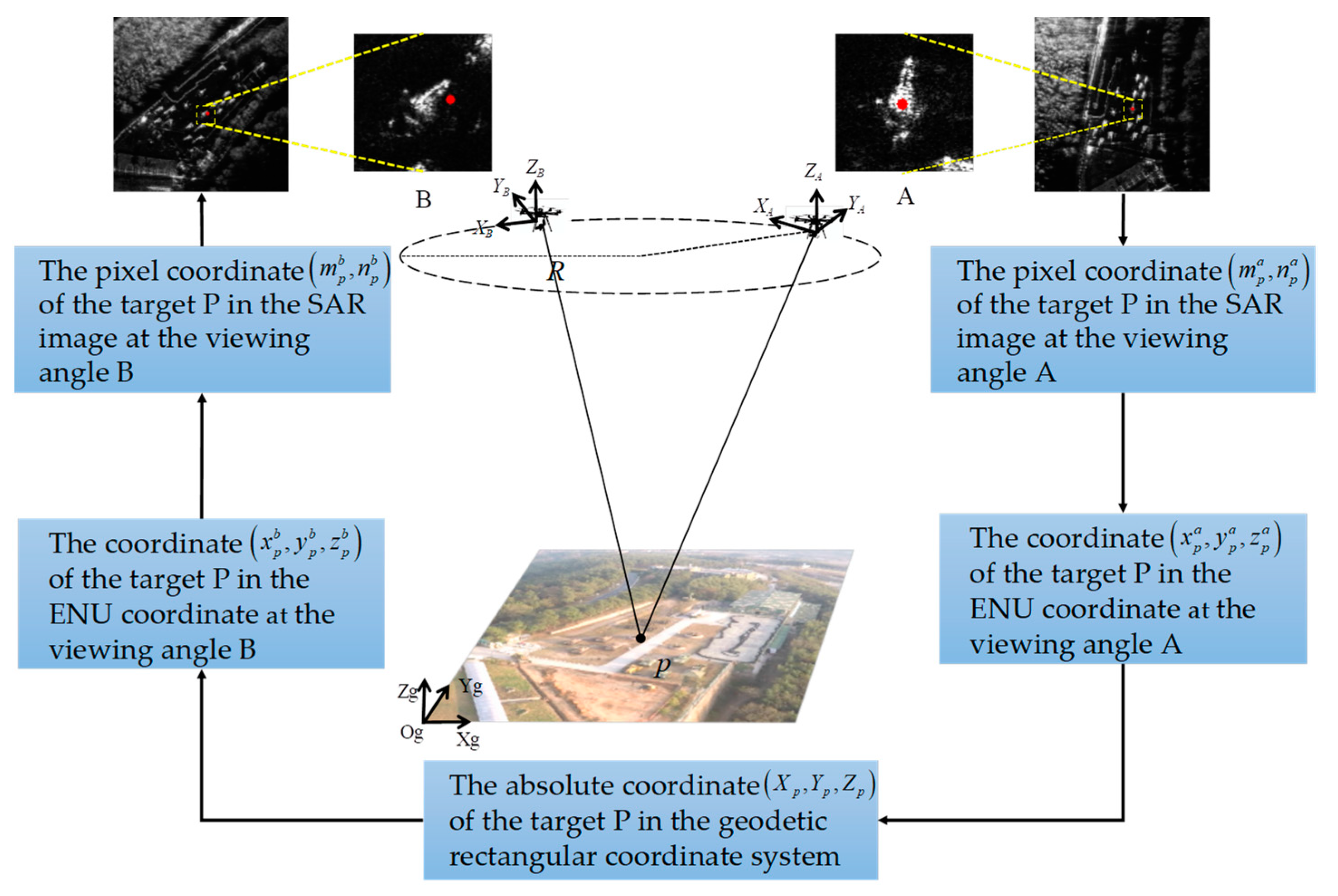
Transformation relationship solution based on inertial information
SAR imaging is performed at different viewing angles in the same scene, and inertial navigation information of the aerial carriers at different viewing angles is obtained. Based on the inertial navigation information and combined with the single-view SAR location model, the preliminary transformation relationship between the SAR images at different viewing angles is obtained through the coordinate transformation among a geodetic coordinate system, ENU (East-North-Up) coordinate system and geodetic rectangular coordinate system.
(3)
Structural similarity matching
According to the transformation relationship, the corresponding coordinates of the feature points of the A-view SAR image on the B-view SAR image is calculated, and the matching points corresponding to the feature points are screened by the nearest neighbor algorithm. The nearest neighbor algorithm and brute force matching algorithm are used to match with the feature points within the neighborhood of matching points, then the matching similarity score is calculated through the neighborhood structure consensus, finally the correct matching is output.

2.1. Target Detection and Extraction

When the aerial carrier images the same target at different positions, the SAR images of the same target will have great shape changes and viewing angle differences due to the position changes of the aerial carrier. The SAR images collected at different time and angles are quite different due to the imaging characteristics of SAR images and the influence of speckle noise and RCS changes at different viewing angles. This makes it difficult to extract the same features from reference images, and the extracted features are not stable enough. Moreover, the extracted features are simple and cannot meet the requirements of high-precision SAR image registration in complex scenes. In the ININSC algorithm, image registration is conducted based on point features. In the process of viewing angle transformation, the structural intersection of targets, the intersection of lines and the local modulus maximum of wavelet transform are affected by SAR image noise and RCS changes. These feature points are not stable. In order to obtain better stability of the extracted feature points in large viewing angle changes, the centroid of the target region of SAR images is taken as the point feature of the matching between the SAR images at different viewing angles.

2.1.1. Preprocessing of SAR Images

In the field of SAR image registration, the difficulty of registration is mainly caused by two factors; one is the influence of noise, and the other is the complex geometric and radiometric differences in the SAR image caused by RCS fluctuation under different viewing angles. The algorithm proposed in this paper mainly depends on the fact that the neighborhood structure of the target does not change in the process of changing the viewing angle of the SAR image, so it only needs to extract the centroid of the main target as the feature point. This is reasonable in military reconnaissance. The targets that need to be located are the ground combat center mainly composed of tanks, anti-aircraft guns, and transport loaders, which are easy to extract. The main reason for converting to the binary image is that it is convenient to extract the centroid of the reconnaissance target. This method can more quickly remove the influence of noise spots and background and is conducive to the subsequent use of the target neighborhood structure for matching.
The background and target are segmented in the SAR images according to the threshold value method, and the SAR images are preliminarily processed. The basic idea of threshold value method is to segment the images into two different regions according to the set threshold values. If the pixel value is smaller than the threshold value, it will be background. If the pixel value is greater than the threshold value, it will be target. In this way, the SAR gray images are changed into binary images to distinguish the target from the background. The threshold value segmentation method features simple calculation and fast segmentation if a threshold value is given. In this paper, the classic threshold value method (OTSU) is adopted to preprocess the SAR images.
OTSU automatically determines the threshold values by using the maximum between-class variance. Variance is used to measure the uniformity of gray distribution. The greater the between-class variance between the background and the target, the greater the difference between the background and target of the images. If part of the targets is misclassified as background or part of the backgrounds are misclassified as target, the difference between both of them will become smaller [29].
M is the number of gray levels and the number of pixels with a gray value i is n i ; the total number of pixels will be N = i = 1 M n i . If the proportion of each gray value after normalization is p i = n i / N , the average gray level of SAR images will be μ = i = 1 M i p i , and the variance will be σ 2 = i = 1 M ( i μ ) 2 p i . If the segmentation threshold value is T , the image is divided into target F 1 and background F 2 , w 1 and w 2 are the probabilities of the emergence of target F 1 and background F 2 , μ 1 and μ 2 are the average gray values, σ 1 2 and σ 2 2 are the variances, then:
w 1 = i = 1 T p i , w 2 = i = T + 1 M p i ,
μ 1 = i = 1 T i p i w 1 , μ 2 = i = T + 1 M i p i w 2 ,
σ 1 2 = 1 w 1 i = 1 T ( i μ 1 ) 2 p i ,   σ 2 2 = 1 w 2 i = 1 T ( i μ 2 ) 2 p i
The between-class variance is:
σ 2 = w 1 ( μ 1 μ 2 ) 2 + w 2 ( μ 1 μ 2 ) 2
If the between-class variance in Equation (4) is a maximum, the gray value T will be the threshold value of the segmented SAR images.
Based on the image morphology method, the SAR images segmented by the threshold value method are conducted with subsequent segmentation processing to reduce the influence of noise on SAR image target detection. The basic idea of morphology is to use structural elements to measure or extract the shapes or features of images. The basic operations include corrosion, expansion, opening operation and closing operation. The opening operation and closing operation are adopted in this paper. Isolated dots and burrs can be effectively removed by the opening operation, and the filtering effect is achieved. Closing operation can fill the gaps between the target images. The principle of opening operation and closing operation is shown in Figure 2. In Figure 2, black squares represent the target, and white squares represent the background.
The results of SAR image preprocessing using the threshold value method and morphology are shown in Figure 3.
In Figure 3, the target has been extracted from the background in the SAR images after preprocessing, but there are still many small noise spots in the processed images and the influence caused by scattering in the wood area.

2.1.2. Target Detection and Feature Extraction

After preprocessing the single-frame SAR images and observing the processing results, images can be divided into three-pixel categories: target pixel region, isolated misjudgment point and strong scattering region. In order to obtain the correct target detection, false alarm suppression is required for other pixel categories beyond the target pixel regions.
(1)
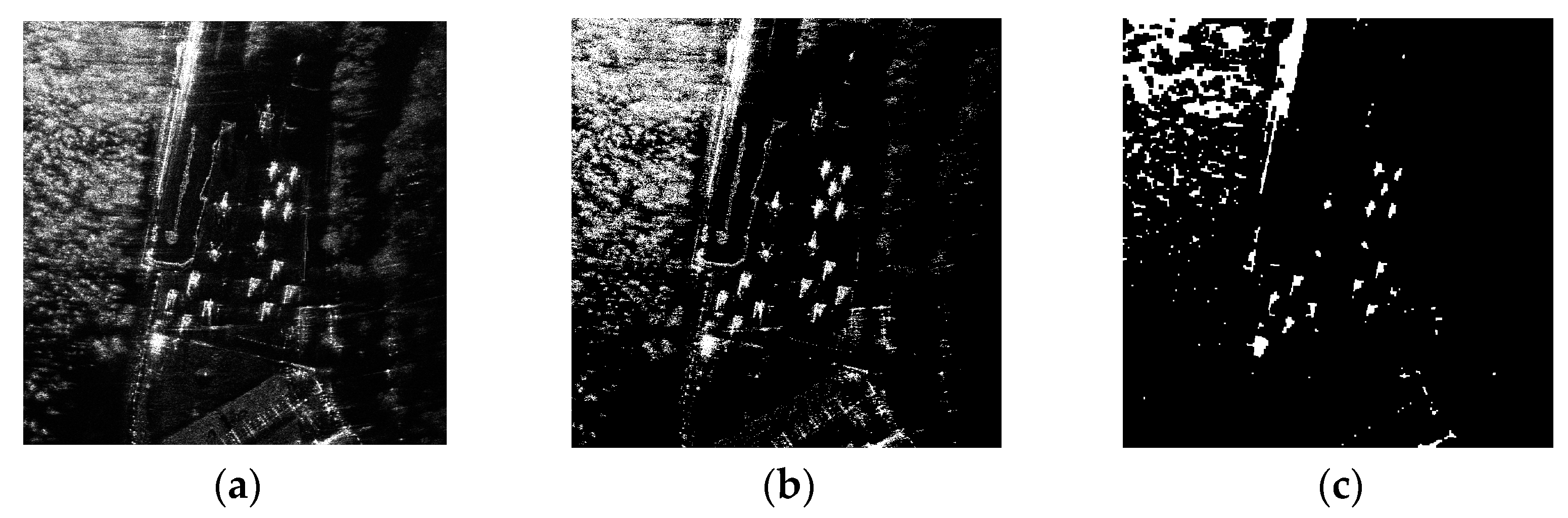
Elimination of isolated misjudgment points
SAR is affected by noise interference in the imaging process, which brings some isolated misjudgment points into the image after preprocessing. In fact, the target occupies a certain area in the image, and it does not exist as an isolated point in the image. Therefore, the maximum connected domain algorithm can be adopted to eliminate the isolated misjudgment points. The connected domain refers to an area composed of adjacent pixels. In the field of computer vision, it is a commonly used image processing technology, which is used to separate different regions in the image, to realize image segmentation, target detection, and other applications. The maximal general domain algorithm is an image processing algorithm based on the connected domain. By setting the maximal general domain pixel threshold, the connected domain greater than the set threshold is extracted. As shown in Figure 4a, isolated misjudgment points are successfully eliminated to obtain some regions with a certain area.
(2)
False alarm suppression in strong scattering region
Target region and strong scattering regions have certain areas in the SAR images, so they can hardly be distinguished using the maximum connected domain method. In practice, there is an obvious regional division between the target region and the strong scattering region dominated by woods. By calculating the connected domain centroid (as shown in Figure 4b, the centroid points of strong scattering region are concentrated and dense), the K-means clustering algorithm can be adopted to separate the target from the strong scattering region to solve this problem [30]. Clustering is a process of classifying and organizing data members that are similar in some aspects. K-means clustering is the most famous partition clustering algorithm. Because of its simplicity and efficiency, it has become the most widely used of all clustering algorithms. Given a set of data points and the required number of clusters K , K is specified by the user, and the K-means algorithm repeatedly divides the data into K clusters according to the distance function. As shown in Figure 4c, the target centroid is obtained after suppressing the strong scattering region, and target detection and feature extraction are completed.
The clustering processing result is shown in Figure 4. The key targets in the single-view SAR images are detected, and the target centroid is used as the feature point of subsequent matching.

2.2. Coordinate Transformation Based on Inertial Navigation Information

Inertial navigation system is a self-aid navigation system which is independent of external information and based on Newton’s laws of motion [31]. Speed, yaw angle and position information in the navigation coordinate system can be obtained by measuring the accelerated speed of the carrier in the inertial reference frame, integrating the time by the accelerated speed of the carrier, and transforming it into the navigation coordinates. Therefore, a model based on inertial navigation information and single-view SAR location is proposed by using the motion information of the aerial carrier to complete preliminary registration.

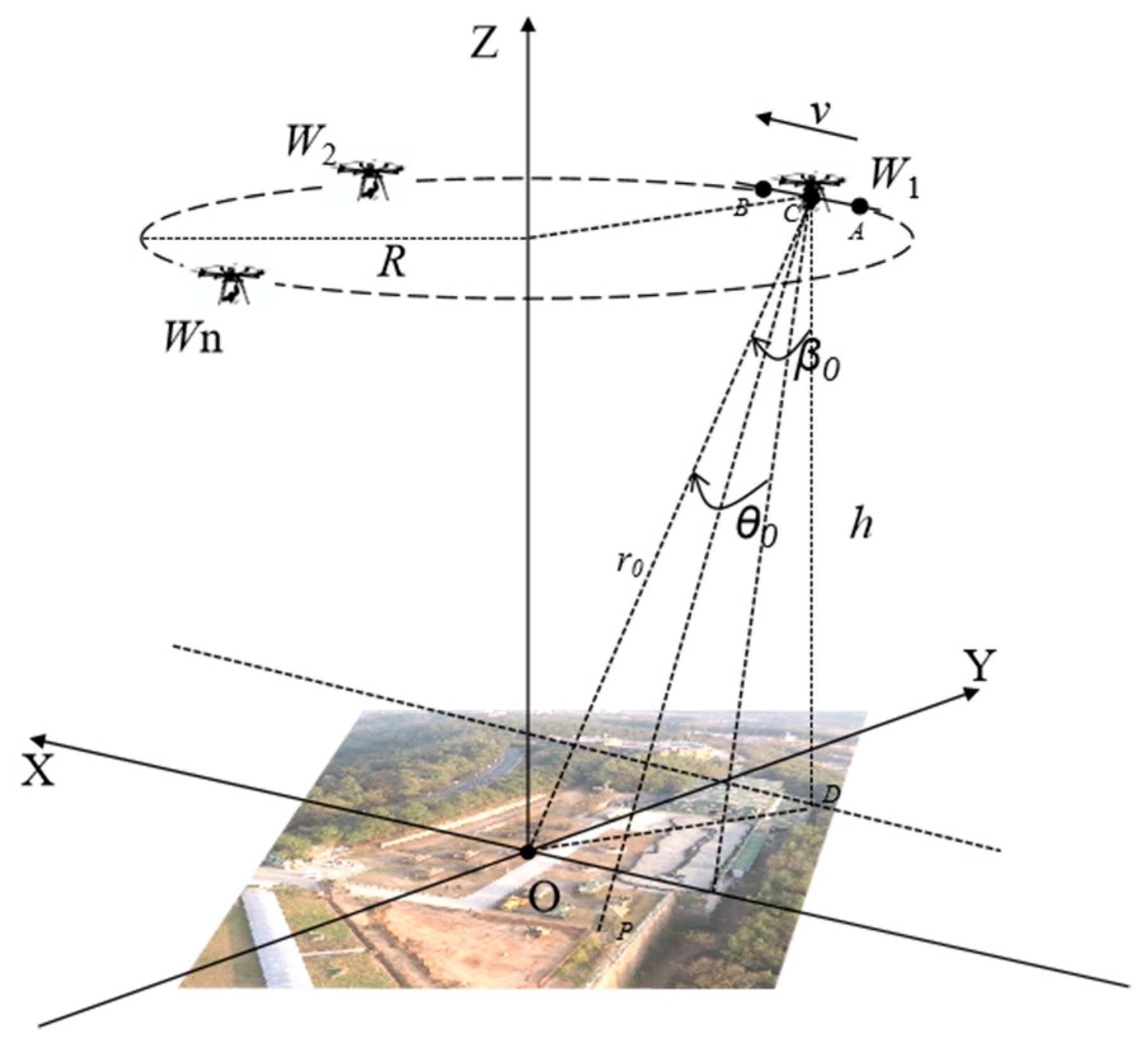
2.2.1. Single-View Location Model

Assuming that the distributed multi-view SAR system conducts SAR imaging for the target region from N different routes ( N is greater than or equal to 3; non-parallel routes intersect with each other and maintain certain included angles, as shown in Figure 5), the target position coordinates can be determined by the position coordinate of the radar antenna phase center during target imaging and its slant range from the target.
Single-view location analysis is carried out for the aerial carrier at the viewing angle W 1 . The location model is shown in Figure 6, and the location analysis of other positions is also carried out in the same way.
As shown in Figure 6, an imaging geometric model is established by taking the point of the radar beam center as an imaging reference point and the imaging reference point as the original point of the coordinate system. The aircraft flies at a constant speed v , the flying altitude is h , and the radar range is r 0 . The starting and ending positions of synthetic aperture are A and B , respectively, and C is the position of the antenna phase center (APC).
Assuming that the squint angle and pitch angle of the aerial carrier at the aperture center point are θ 0 and β 0 , respectively, the coordinate of APC at the aperture center point is ( x 0 , y 0 , z 0 ) :
{ x 0 = h cos ( β 0 ) × sin ( θ 0 ) y 0 = ( h × tan ( β 0 ) ) 2 x 0 2 z 0 = h
Assuming that the components of the speed of the aerial carrier along the three coordinate axes are V x , V y and V z , respectively and the positive direction of the speed is the same as that of the coordinate axis, the coordinate of APC at any time can be given as follows:
{ x a p c ( t ) = x 0 + V x t y a p c ( t ) = y 0 + V y t z a p c ( t ) = z 0 + V z t
The instantaneous coordinate of the APC is ( x a p c ( t ) , y a p c ( t ) , z a p c ( t ) ) , and the imaging center point is the original point. If the coordinate of the ground target P is ( x p , y p , 0 ) , the real-time distance from APC to the ground target can be obtained as follows:
r p ( t ) = ( x a p c ( t ) x p ) 2 + ( y a p c ( t ) y p ) 2 + z a p c ( t ) 2
According to the definition of the Doppler frequency, the Doppler frequency of the target P is:
f p = 2 λ d r p ( t ) d t
where λ is the electromagnetic wave wavelength. In z 0 = h , h is the flight altitude of the aerial carrier. The range Doppler equation can be obtained as follows:
{ r = ( x 0 x p ) 2 + ( y 0 y p ) 2 + h 2 f p = 2 V x ( x 0 x p ) 2 V y ( y 0 y p ) 2 V z h λ ( x 0 x p ) 2 + ( y 0 y p ) 2 + h 2
where r is the distance between the APC and the target P , and f p is the Doppler frequency of the target P . Assuming that the pixel coordinate of any point p in the SAR image is ( n , m ) , the corresponding distance and Doppler frequency can be obtained:
{ r = r r e f + ( n N r / 2 ) p r f p = f d c + ( m N a / 2 ) Δ f d
where n is the pixel coordinate in the range direction, m is the pixel coordinate in the azimuth direction, r r e f is the reference slant range from the aperture center point to the imaging reference point, f d c is the Doppler frequency of the imaging reference point, N a is the number of sampling points in the azimuth direction, N r is the number of sampling points in the distance direction, p r is the distance represented by each pixel unit in the distance direction of SAR image, and Δ f d is the Doppler frequency represented by each pixel point in the azimuth direction. Substituting r and f p of Equation (10) into Equation (9), the corresponding x p and y p can be obtained.
The coordinate ( x p , y p , 0 ) corresponding to any pixel point ( n , m ) in the SAR image can be obtained according to Equations (9) and (10).

2.2.2. Coordinate System Transformation

In the same scene, the pixel point position information of the target P is different in the SAR images at different positions. In fact, the target P is stationary, which means that the position of the target P in the geodetic rectangular coordinate system is fixed. The preliminary registration of SAR images at different positions can be realized through the coordinate system transformation.
Assuming that the coordinates of the target P in the ENU coordinate system and the geodetic rectangular coordinate system are ( x p , y p , z p ) and ( X p , Y p , Z p ) , respectively, the coordinate transformation relationship can be obtained as follows:
[ X p Y p Z p ] = [ sin L 0 cos L 0 0 cos L 0 sin L 0 0 0 0 1 ] [ 1 0 0 0 sin B 0 cos B 0 0 cos B 0 sin B 0 ] [ x p y p z p ] + [ X 0 Y 0 Z 0 ] = [ sin L 0 sin B 0 cos L 0 cos B 0 cos L 0 cos L 0 sin B 0 sin L 0 cos B 0 sin L 0 0 cos B 0 sin B 0 ] [ x p y p z p ] + [ X 0 Y 0 Z 0 ]
where ( X 0 , Y 0 , Z 0 ) is the coordinate of the original point O of the ENU coordinate in the geodetic rectangular coordinate system. ( L 0 , B 0 , H 0 ) is the geodetic coordinate of the aperture center point, where L 0 is longitude, B 0 is latitude, and H 0 is altitude. The geodetic coordinate ( L 0 , B 0 , H 0 ) of the aperture center point is given by the aerial carrier platform system.
Assuming that when the aerial carrier is at the viewing angle A , the pixel coordinate of the target P in the SAR image is ( m p a , n p a ) , the ENU coordinate ( x p a , y p a , z p a ) of the target P at the viewing angle A can be obtained through the location model at a single viewing angle. The absolute position information ( X p , Y p , Z p ) of the target P in the geodetic rectangular coordinate system is obtained after substituting it into Equation (11). According to the inertial navigation information of the aerial carrier at the viewing angle B , the ENU coordinate ( x p b , y p b , z p b ) of the target P is obtained through Equation (11) when the aerial carrier is at the viewing angle B . After substituting the coordinate into Equations (9) and (10), the pixel coordinate ( m p b , n p b ) of the target P is obtained when the aerial carrier is at the viewing angle B . The operation flow is shown in Figure 7:
Through the above method, a connection is established between the pixel point position in the SAR image when the aerial carrier is at the viewing angle A and the pixel point position in the SAR image when the aerial carrier is at the viewing angle B . However, due to the error of the parameters given by the aerial carrier platform, the pixel point coordinate obtained by this method is not completely accurate. The range of target matching can be reduced in this way, which greatly improves the accuracy of target matching and reduces the matching time.
O g , X g , Y g and Z g represent the earth rectangular coordinate system, X A , Y A and Z A represent the northeast celestial coordinate system centered on carrier a , and X B , Y B and Z B represent the northeast celestial coordinate system centered on carrier b .

2.3. Matching Algorithm Based on Structural Similarity

After the target detection and feature extraction of SAR images, how to match them accurately and quickly has become a problem to be solved [32]. The matching strategy of the proposed ININSC algorithm is to use inertial navigation information for preliminary nearest neighbor screening, and all the feature points in the screening range may be the corresponding matching of the target at another viewing angle [33]. In order to solve the problem of matching between targets and feature points, a matching method based on structural similarity is adopted. The target and its corresponding matching feature points at different viewing angles as well as other corresponding reference feature points in their neighborhoods should maintain a consistent spatial structure relationship [34].
Assuming that the target P has K candidate points within the neighborhood at the viewing angle B after preliminary registration through inertial navigation information, these K candidate points may be correctly matched with the target P . Through nearest-neighbor and brute-force matching, the reference points around these K candidate points and the reference points in the neighborhood of the target P at the position A are quickly matched to obtain K matching results I . Only one of these K matching results is a correct matching result. The ININSC algorithm solves the matching problem by designing a structural similarity function.
To define the similarity of each match, this paper designs a method to calculate the similarity score. The higher the score, the higher the similarity of this match. As shown in Figure 8, the red point represents the target P , the yellow point represents the reference point near the target, the left image represents the original image, and the middle image represents the position of the feature points on the original image on the registration image after the inertial navigation information conversion, and the right is the registration image. Two point sets O and C are defined to store the target and the reference points near the target, respectively. In O = ( p 0 , q 0 ) , p 0 is the coordinate of the target P at the viewing angle A , and q 0 is the coordinate of the possible candidate point of the target at the viewing angle B . In C = { ( p i , q i ) } i = 1 N , p i and q i are the coordinates of the paired matching points when the O matching is correct.
This paper measures the similarity from three perspectives: distance, angle and vector.
(1)
Distance similarity
The distance between the target and the reference point is constant in the process of changing the viewing angle. But in the actual matching process, the distance cannot be exactly the same. Define d ( x , y ) as the distance between two points of x , y . As shown in Figure 8, d ( p 0 , p 1 ) and d ( q 0 , q 1 ) are not exactly the same, but the difference between the lengths of the corresponding edges should be approximately the same. The difference between d ( p 0 , p 2 ) and d ( q 0 , q 2 ) is approximately the same as that between d ( p 0 , p 1 ) and d ( q 0 , q 1 ) . Therefore, the distance similarity function is defined as follows:
S ( O , C ) = i = 1 N 1 N e | d ( p 0 , p i ) d ( q 0 , q i ) | m a x ( d ( p 0 , p i ) , d ( q 0 , q i ) )
where 1 N stands for weight.
(2)
Angle similarity
In the process of changing the viewing angle, the angle between the target and any two reference points is constant. But in the actual matching process, the angles cannot be exactly the same. θ ( x , y , z ) is defined as the angle formed by x as the vertex in x , y , z . As shown in Figure 8, θ ( p 0 , p i , p j ) and θ ( q 0 , q i , q j ) are not exactly the same, so the ratio is used to form the angle consistency, and the angle similarity function is defined as follows:
G ( I ; O , C ) = S ( O , C ) + R ( O , C ) + V ( O , C )
where C N 2 represents the number of combinations of two elements taken from N different elements and 1 C N 2 stands for weight.
(3)
Vector similarity
As shown in Figure 8, v 0 is a vector pointing from p 0 to q 0 , and v i is a vector pointing from p i to q i . For correctly matched points, the displacement vector between any two points in its neighborhood should be very close. For mismatched points, the displacement vectors of points in the neighborhood and between points may be different. Therefore, the product of the length ratio and the angle between two displacement vectors is used to describe the consistency between the two vectors, and the vector consistency function is defined as follows:
V ( O , C ) = i = 1 N 1 N m i n ( | v i | , | v 0 | ) m a x ( | v i | , | v 0 | ) ( v i , v 0 ) | v i | , | v 0 |
where 1 N stands for weight.
The structural similarity function is equal to the sum of the distance, angle and vector consistency functions, as follows:
G ( I ; O , C ) = S ( O , C ) + R ( O , C ) + V ( O , C )
Therefore, when the structural similarity function reaches the maximum value, the best matching result I can be obtained as follows:
I * = a r g m a x G ( I ; O , C )
By using the neighborhood structure consistency of feature points, the correct matching point group is obtained. It is assumed that the transformation between SAR images is the affine transformation in the process of view angle change. The affine transformation matrix between two images is obtained by matching the point group. Through the affine transformation matrix, the registration between two images can be realized, and each part of the image will correspond to each other.

3. Experimental Verification

In order to verify the accuracy and advantages of the ININSC algorithm, the ININSC algorithm is compared with the two traditional SAR registration methods. The first algorithm is SAR-SIFT algorithm, which is improved from the SIFT algorithm. The feature point pair registration method based on gradient calculation has a good effect on SAR image registration. The second algorithm is the PSO-SIFT algorithm, which uses a transformation for the speckle noise of SAR images and has a good registration effect in the field of SAR image registration.

3.1. Data Description and Parameter Settings

The X/Ku-band NUAA MiniSAR system [35] used in the experiment was independently developed by the research team of radar detection and imaging technology of Nanjing University of Aeronautics and Astronautics in 2017. It adopts the frequency modulated continuous wave system with a resolution of 0.1 m and a mass of only 5 kg. The main parameters are shown in Table 1. The carrying platform is a UAV (Unmanned Aerial Vehicle) with eight rotary wings, and the aerial flight attitude diagram of the system is shown in Figure 9.
The data source of the experiment is from the field flight test in a national defense park of Nanjing from 2021 to 2022 by using the MiniSAR system of Nanjing University of Aeronautics and Astronautics. In this experiment, the typical ground military targets such as tanks and armored vehicles in the park were observed in all directions, a large amount of echo data were collected, and the SAR target data sets taking the national defense park as a circumference range was preliminarily built. The imaging mode of the MiniSAR system was circular spotlight SAR, and the system parameters were set as flight height (500 m), flight speed (5 m/s), azimuth angle (0°~360°) and observation pitch angle (45°). The field experiment observation image is shown in Figure 10, in which the military operation targets were marked.
The echo data sets obtained from the experiment were imaged by the back project (BP) algorithm, there were totally 100 frame images. The size of the images is 1024 × 1024. The viewing angle interval between the frames was approximately 1.8°, and the images were saved in tif format. The viewing angle difference between the adjacent frames was small. In order to obtain a certain viewing angle difference, some images were selected at a certain interval for experimental verification. As shown in Figure 11, the images of the 1st frame, the 18th frame and the 35th frame were selected for experiment, assuming that the viewing angles of the 1st frame, the 18th frame and the 35th frame were 0°, 30.6° and 61.2°, respectively.
A 64-bit Win10 operation system, 8G memory and Intel (R) Core (TM) i5-9600KF processor were provided in the experiment. During the experiment, GPU was not used for optimization. The experimental software was MatlabR2020a. SAR-SIFT, PSO-SIFT and ININSC algorithms run on the Matlab platform. The parameter settings of SAR-SIFT and PSO-SIFT algorithms were the default settings in related articles, and they used the RANSAC algorithm to eliminate the mismatching points.
The setting of the maximum connected domain threshold parameter was based on the prior conditions, mainly on the actual size of the target to be separated and the resolution of the remote sensing image. The remote sensing imaging resolution of the MiniSAR system used in this paper was 0.1 m. The actual tank was about 7.3 m long and 3.5 m wide, occupying 640 pixel units in the image. To ensure that the target was detected, the threshold of the largest connected domain was set to 500, and the connected domain greater than 500 was regarded as the target. The parameter K of the K-means clustering algorithm is set to 2 to separate the two clusters of the target region and strong scattering region.

3.2. Comparative Experiment Results and Analysis

The SAR images at the viewing angles 0°, 30.6° and 61.2°constituted three pairs of test image groups: 0°and 30.6°; 0°and 61.2°; and 30.6° and 61.2°. The registration results after adopting the ININSC algorithm and other two algorithms are shown in Figure 12, Figure 13 and Figure 14. After registration, the transformation matrix between the SAR images at different viewing angles was calculated through the matching points, and the registration error of SAR images was calculated by the transformation matrix obtained by the three algorithms. As shown in Figure 10, there were many military operation targets in the national defense park, and whether the key operation targets at different viewing angles could be correctly matched was considered as an indicator for accurate matching.
Subjective evaluation and objective evaluation were adopted in the experiment. The method of subjective evaluation was used to judge the connection of registration points and the correctness of such connection. After three pairs of images were registered, the checkers were spliced in Figure 12, Figure 13 and Figure 14. The registration effect was judged subjectively for detailed splicing. The evaluation indicators adopted in the objective evaluation included the root-mean-squared error (RMSE), time, and matching rate of key operation targets.
The RMSE equation is as follows:
RMSE = i = 1 N ( I 1 i I 2 i ) 2 N
where I 1 is the SAR image at the initial viewing angle, I 2 is the image of SAR at different viewing angles after the transformation matrix is registered and calculated, I 1 i and I 2 i are the gray values of the corresponding points, N is the total number of pixels in the overlapping part, and RMSE is the image registration accuracy. The smaller the RMSE value, the higher the registration accuracy.
The matching ratio η equation of key operation targets is as follows:
η = M M 0 × 100 %
where M is the number of key operation targets that are correctly matched after registration, and M 0 is the total number of key operation targets. If accurate registration can be realized in the proposed algorithm, the matching rate of key operation targets should be 100%.
The time represents the processing time of a single target.
According to Table 2, compared with PSO-SIFT and SAR-SIFT, the matching rate of key operation targets was 100% in the first two pairs of test image groups in the ININSC algorithm, the RMSE values were approximate, and the corresponding registration accuracy was equally good. The processing time of the ININSC algorithm was an order of magnitude less than that of the other two algorithms, which objectively verified the effectiveness and timeliness of the ININSC algorithm. In the third group, the matching rate of key operation targets of the first two algorithms was 0, and RMSE could not be calculated. The reason why the RMSE could not be computed is that the feature points match incorrectly, as shown in Figure 14. This indicated that the first two algorithms were no longer applicable to this situation. In this case, the matching rate of key operation targets in the ININSC algorithm was still 100%. The ININSC algorithm was more robust than PSO-SIFT and SAR-SIFT in processing the differences at large viewing angles.
The viewing angle differences between the first pair of the images and the second pair of the images in the test image groups were 30.6°, and there were slight differences in rotation, translation and scaling as well as noise interference. The registration results are shown in Figure 12 and Figure 13. SAR-SIFT, PSO-SIFT and ININSC algorithms achieved accurate matching results in this case. It can be seen from the intuitive checker mosaic images that the SAR images at different viewing angles were connected well in details, and the ground targets overlapped completely after registration. When the viewing angle difference was small, the three algorithms achieved good registration results.
Compared with the first two test groups, the third pair of test groups had a viewing angle difference of 61.2°. The differences caused by rotation, translation, scaling, RCS and noise were even greater, and the geometric distortion of the target increased. The registration result is shown in Figure 14. The SAR-SIFT and PSO-SIFT algorithms lost their accuracy in matching points, the number of matching points was small, and the connection of registration points was wrong. These two algorithms were no longer applicable to the third pair of the test group. In the ININSC algorithm, the registration points were connected accurately, the registered images were connected accurately after checkers were spliced, and the ground targets were overlapped well. The ININSC algorithm still achieved a good registration result, while the other two algorithms could not adapt to the matching at large viewing angles.
The first frame was considered as the image to be registered, and there was only a slight viewing angle difference (less than 9°) among the 2nd to 5th frames in the data sets. Thus, the SAR image after the 6th frame (a viewing angle difference of about 9° between the 6th frame and the 1st frame) was selected to conduct image registration with the 1st frame. The RMSE results of SAR-SIFT, PSO-SIFT and ININSC algorithms are shown in Figure 15, and the average time is shown in Figure 16.
It can be clearly seen from Figure 15 that the registration accuracy of the ININSC algorithm was the same as SAR-SIFT and PSO-SIFT when correct registration was achieved. Whenever a viewing angle difference is greater than 60°, SAR-SIFT and PSO-SIFT could not be registered correctly with the 1st frame image. However, the ININSC algorithm could still achieve accurate registration. The ININSC algorithm could be used to process the matching at large viewing angles, which was hardly processed by traditional algorithms. It can be clearly seen from Figure 16 that the average time of the ININSC algorithm was far less than that of other two traditional algorithms.
In the three pairs of test groups, the connection of registration points in the ININSC algorithm were uniform and accurate, and the results of checker mosaic images after registration showed that the detail connection was accurate and the registration effect was good. Compared with SAR-SIFT and PSO-SIFT algorithms, the ININSC algorithm could still obtain accurate registration results under the great differences in test images. It can be seen from Table 2 that the ININSC algorithm had low RMSE, the registration accuracy was as good as the other two algorithms, and its time consumption was far less than the other two algorithms.
The simulation results of a large amount of data are shown in Figure 15 and Figure 16. The accuracy of the proposed INIANS algorithm could be compared favorably with the SAR-SIFT and PSO-SIFT algorithms, and it could solve the problem of differences at large viewing angles that was difficultly handled by traditional algorithms. Its time consumption was far lower than the other two algorithms. Compared with the other two traditional algorithms, the ININSC algorithm had better robustness and timeliness.

4. Discussion

In the three pairs of test groups, the connection of registration points in the ININSC algorithm were uniform and accurate, and the results of checker mosaic images after registration showed that the detail connection was accurate and the registration effect was good. Compared with SAR-SIFT and PSO-SIFT algorithms, the ININSC algorithm could still obtain accurate registration results under the great differences in test images. It can be seen from Table 2 that ININSC algorithm had low RMSE, the registration accuracy was as good as the other two algorithms, and its time consumption was far less than the other two algorithms.
The simulation results of a large amount of data are shown in Figure 15 and Figure 16. The accuracy of the proposed ININSC algorithm could be compared favorably with SAR-SIFT and PSO-SIFT algorithms, and it could solve the problem of differences at large viewing angles that was difficultly handled by traditional algorithms. Its time consumption was far lower than the other two algorithms. Compared with the other two traditional algorithms, ININSC algorithm had better robustness and timeliness.
The reason why SAR-SIFT and PSO-SIFT fail is that their method based on sift uses artificially designed descriptors for matching. This method depends on the similarity of target regions to a certain extent. In the case of large angle difference, the similarity between SAR images decreases sharply in the face of the complex geometric and radiometric differences of SAR images. As shown in Figure 17, due to the backscattering coefficient, the similarity of the same target area at different angles of SAR image is very poor, and the feature points described based on SIFT algorithm are difficult to match correctly in this case. In this case, the spatial structure relationship between the target and the nearby reference object is invariant, and the ININC algorithm uses this feature to complete the matching. The 61° mentioned in the article is for the experimental data, and the main influence is the imaging conditions. According to the data generated by different equipment and in different positions, the unmatched angle will change.
In terms of extracting feature points, the advantage of ININSC algorithm is that it can detect and separate targets without a large number of sample data sets compared with the deep learning method. Compared with the traditional SAR image registration algorithms SAR-SIFT and PSO-SIFT, the traditional algorithm is based on SIFT algorithm to extract feature points from SAR images. The feature points extracted by SIFT algorithm include the noise speckle signal in SAR image, which will cause difficulties for subsequent matching, increase the matching time, and easily form false matching.
The proposed algorithm has the following limitations: the algorithm has certain requirements for hardware facilities, needs to be equipped with the inertial navigation system, and the cost will be higher than the traditional algorithm. Another disadvantage is that the target and background need to be significantly distinguished, which can make the target accurately extracted.

5. Conclusions

In this paper, a fast matching method for the SAR images with large viewing angles based on inertial navigation information and neighborhood structure consensus was proposed, which consisted of target detection and extraction, coordinate transformation based on inertial navigation information, and a matching algorithm based on neighborhood structure consensus. The experimental results demonstrate the following:
(1)
The ININSC algorithm has the same registration accuracy as the traditional SAR image registration algorithms and can solve the problem of SAR image registration at large viewing angles that the traditional algorithm cannot tackle. It has stronger robustness.
(2)
The ININSC algorithm is far less time-consuming than traditional SAR image registration algorithms.
The above research results have an important reference value in the application field of SAR image registration engineering. Compared with traditional SAR image registration algorithms, the ININSC algorithm does not only meet the requirements of multi-view target location accuracy under the differences at large viewing angles, but also greatly reduces the time consumption of the SAR image matching at large viewing angles.

Author Contributions

Conceptualization, H.Y.; Methodology, H.Y.; Software, R.Z.; Validation, R.Z.; Formal analysis, C.W.; Investigation, C.W.; Data curation, R.Z.; Writing—original draft, R.Z.; Writing—review & editing, R.Z.; Supervision, D.W. and D.Z.; Project administration, L.W.; Funding acquisition, G.Z. All authors have read and agreed to the published version of the manuscript.

Funding

This research was funded by the National Natural Science Foundation of China (grant number 62271252 and 62171220).

Conflicts of Interest

The authors declare no conflict of interest.

References

  1. Fan, W.; Zhang, M.; Li, J.; Wei, P. Modified Range-Doppler Algorithm for High Squint SAR Echo Processing. IEEE Geosci. Remote Sens. Lett. 2019, 16, 422–426. [Google Scholar] [CrossRef]
  2. Salerno, E. Using Low-Resolution SAR Scattering Features for Ship Classification. IEEE Geosci. Remote Sens. Lett. 2022, 19, 1–4. [Google Scholar] [CrossRef]
  3. Zhu, M.; Hu, G.; Zhou, H.; Wang, S. Multiscale Ship Detection Method in SAR Images Based on Information Compensation and Feature Enhancement. IEEE Trans. Geosci. Remote Sens. 2022, 60, 1–13. [Google Scholar] [CrossRef]
  4. Ansari, H.; De Zan, F.; Parizzi, A.; Eineder, M.; Goel, K.; Adam, N. Measuring 3-D Surface Motion with Future SAR Systems Based on Reflector Antennae. IEEE Geosci. Remote Sens. Lett. 2016, 13, 272–276. [Google Scholar] [CrossRef]
  5. Yuan, M.; Zhang, Q.; Li, Y.; Yan, Y.; Zhu, Y. A Suspicious Multi-Object Detection and Recognition Method for Millimeter Wave Sar Security Inspection Images Based on Multi-Path Extraction Network. Remote Sens. 2021, 13, 4978. [Google Scholar] [CrossRef]
  6. Lavalle, M.; Seker, I.; Ragan, J.; Loria, E.; Ahmed, R.; Hawkins, B.P.; Prager, S.; Clark, D.; Beauchamp, R.; Haynes, M.; et al. Distributed Aperture Radar Tomographic Sensors (DARTS) to Map Surface Topography and Vegetation Structure. In Proceedings of the 2021 IEEE International Geoscience and Remote Sensing Symposium IGARSS, Brussels, Belgium, 11–16 July 2021; pp. 1090–1093. [Google Scholar]
  7. Fan, Y.; Chen, X.; Wei, Y.; Wen, Y.; Zeng, T.; DIng, Z. The Distributed SAR Reconstruction Method for Line Target. In Proceedings of the 2019 IEEE International Conference on Signal, Information and Data Processing (ICSIDP), Chongqing, China, 11–13 December 2019; pp. 2921–2924. [Google Scholar] [CrossRef]
  8. Markiewicz, J.; Abratkiewicz, K.; Gromek, A.; Ostrowski, W.; Samczyński, P.; Gromek, D. Geometrical Matching of SAR and Optical Images Utilizing ASIFT Features for SAR-Based Navigation Aided Systems. Sensors 2019, 19, 5500. [Google Scholar] [CrossRef]
  9. Liu, X.; Li, J.B.; Pan, J.S.; Wang, S.; Lv, X.; Cui, S. Image-Matching Framework Based on Region Partitioning for Target Image Location. Telecommun. Syst. 2020, 74, 269–286. [Google Scholar] [CrossRef]
  10. Suri, S.; Reinartz, P. Mutual-Information-Based Registration of TerraSAR-X and Ikonos Imagery in Urban Areas. IEEE Trans. Geosci. Remote Sens. 2010, 48, 939–949. [Google Scholar] [CrossRef]
  11. Yoo, J.C.; Han, T.H. Fast Normalized Cross-Correlation. Circuits Syst. Signal Process. 2009, 28, 819–843. [Google Scholar] [CrossRef]
  12. Wang, F.; Vemuri, B.C. Non-Rigid Multi-Modal Image Registration Using Cross-Cumulative Residual Entropy. Int. J. Comput. Vis. 2007, 74, 201–215. [Google Scholar] [CrossRef]
  13. Paul, S.; Pati, U.C. SAR Image Registration Using an Improved SAR-SIFT Algorithm and Delaunay-Triangulation-Based Local Matching. IEEE J. Sel. Top. Appl. Earth Obs. Remote Sens. 2019, 12, 295–2966. [Google Scholar] [CrossRef]
  14. Hughes, R.A. Geoscience Data and Derived Spatial Information: Societal Impacts and Benefits, and Relevance to Geological Surveys and Agencies. Spec. Pap. Geol. Soc. Am. 2011, 482, 35–40. [Google Scholar] [CrossRef]
  15. Fan, B.; Huo, C.; Pan, C.; Kong, Q. Registration of Optical and Sar Satellite Images by Exploring the Spatial Relationship of the Improved SIFT. IEEE Geosci. Remote Sens. Lett. 2013, 10, 657–661. [Google Scholar] [CrossRef]
  16. Dellinger, F.; Delon, J.; Gousseau, Y.; Michel, J.; Tupin, F. SAR-SIFT: A SIFT-like Algorithm for SAR Images. IEEE Trans. Geosci. Remote Sens. 2015, 53, 453–466. [Google Scholar] [CrossRef]
  17. Ma, W.; Wen, Z.; Wu, Y.; Jiao, L.; Gong, M.; Zheng, Y.; Liu, L. Remote Sensing Image Registration with Modified Sift and Enhanced Feature Matching. IEEE Geosci. Remote Sens. Lett. 2017, 14, 3–7. [Google Scholar] [CrossRef]
  18. Eltanany, A.S.; Amein, A.S.; Elwan, M.S. A Modified Corner Detector for SAR Images Registration. Int. J. Eng. Res. Afr. 2021, 53, 123–156. [Google Scholar] [CrossRef]
  19. Elwan, M.; Amein, A.S.; Mousa, A.; Ahmed, A.M.; Bouallegue, B.; Eltanany, A.S. SAR Image Matching Based on Local Feature Detection and Description Using Convolutional Neural Network. Secur. Commun. Netw. 2022, 2022, 5669069. [Google Scholar] [CrossRef]
  20. Yao, G.; Man, X.; Zhang, L.; Deng, K.; Zhuang, H.; Zheng, G. Registrating Oblique SAR Images Based on Complementary Integrated Filtering and Multilevel Matching. IEEE J. Sel. Top. Appl. Earth Obs. Remote Sens. 2019, 12, 3445–3457. [Google Scholar] [CrossRef]
  21. Xiang, Y.; Jiao, N.; Liu, R.; Wang, F.; You, H.; Qiu, X.; Fu, K. A Geometry-Aware Registration Algorithm for Multiview High-Resolution SAR Images. IEEE Trans. Geosci. Remote Sens. 2022, 60, 1–18. [Google Scholar] [CrossRef]
  22. Xiang, Y.; Peng, L.; Wang, F.; Qiu, X. Fast Registration of Multiview Slant-Range SAR Images. IEEE Geosci. Remote Sens. Lett. 2022, 19, 1–5. [Google Scholar] [CrossRef]
  23. Oveis, A.H.; Giusti, E.; Ghio, S.; Martorella, M. A Survey on the Applications of Convolutional Neural Networks for Synthetic Aperture Radar: Recent Advances. IEEE Aerosp. Electron. Syst. Mag. 2022, 37, 18–42. [Google Scholar] [CrossRef]
  24. Zhang, Z.; Xu, Y.; Cui, Q.; Zhou, Q.; Ma, L. Unsupervised SAR and Optical Image Matching Using Siamese Domain Adaptation. IEEE Trans. Geosci. Remote Sens. 2022, 60, 1–16. [Google Scholar] [CrossRef]
  25. Du, W.L.; Zhou, Y.; Zhao, J.; Tian, X.; Yang, Z.; Bian, F. Exploring the Potential of Unsupervised Image Synthesis for SAR-Optical Image Matching. IEEE Access 2021, 9, 71022–71033. [Google Scholar] [CrossRef]
  26. Bozeman, E.; Nguyen, M.; Alam, M.; Onners, J. Inertial Navigation Compensation with Reinforcement Learning. In Proceedings of the 2022 IEEE International Symposium on Inertial Sensors and Systems (INERTIAL), Avignon, France, 8–11 May 2022; pp. 1–4. [Google Scholar] [CrossRef]
  27. Jiang, X.; Xia, Y.; Zhang, X.P.; Ma, J. Robust Image Matching via Local Graph Structure Consensus. Pattern Recognit. 2022, 126, 108588. [Google Scholar] [CrossRef]
  28. Ma, J.; Zhao, J.; Jiang, J.; Zhou, H.; Guo, X. Locality Preserving Matching. Int. J. Comput. Vis. 2019, 127, 512–531. [Google Scholar] [CrossRef]
  29. AlSaeed, D.H.; Bouridane, A.; ElZaart, A.; Sammouda, R. Two Modified Otsu Image Segmentation Methods Based on Lognormal and Gamma Distribution Models. In Proceedings of the 2012 International Conference on Information Technology and e-Services, Sousse, Tunisia, 24–26 March 2012; pp. 1–5. [Google Scholar] [CrossRef]
  30. Venkatachalam, K.; Reddy, V.P.; Amudhan, M.; Raguraman, A.; Mohan, E. An Implementation of K-Means Clustering for Efficient Image Segmentation. In Proceedings of the 2021 10th IEEE International Conference on Communication Systems and Network Technologies (CSNT), Bhopal, India, 18–19 June 2021; pp. 224–229. [Google Scholar] [CrossRef]
  31. Zhao, W.; Zhou, L.; Song, G. A Study on Alignment of Analytic Space Stable Inertial Navigation System. In Proceedings of the 2019 26th Saint Petersburg International Conference on Integrated Navigation Systems (ICINS), St. Petersburg, Russia, 27–29 May 2019; pp. 6–11. [Google Scholar] [CrossRef]
  32. Lu, X.; Du, S. Nctr: Neighborhood Consensus Transformer for Feature Matching. In Proceedings of the 2022 IEEE International Conference on Image Processing (ICIP), Bordeaux, France, 16–19 October 2022; pp. 2726–2730. [Google Scholar] [CrossRef]
  33. Liu, H.; Yan, S. Common Visual Pattern Discovery via Spatially Coherent Correspondences. In Proceedings of the 2010 IEEE Computer Society Conference on Computer Vision and Pattern Recognition, San Francisco, CA, USA, 13–18 June 2010; pp. 1609–1616. [Google Scholar] [CrossRef]
  34. Jiang, B.; Sun, P.; Zhang, Z.; Tang, J.; Luo, B. GAMnet: Robust Feature Matching via Graph Adversarial-Matching Network. In Proceedings of the 29th ACM International Conference on Multimedia, Chengdu, China, 20–24 October 2021; pp. 5419–5426. [Google Scholar] [CrossRef]
  35. Zhang, Y.; Zhu, D.; Mao, X.; Zhang, G.; Leung, H. Multirotor UAV-Borne Repeat-Pass CSM-VideoSAR. IEEE Trans. Aerosp. Electron. Syst. 2022, 58, 2601–2605. [Google Scholar] [CrossRef]
Figure 1. Realization flow of the ININSC algorithm.
Remotesensing 15 04084 g001
Figure 2. Processing examples of the principle of morphological opening operation and closing operation: (a) original image; (b) structural element; (c) opening operation; (d) closing operation.
Remotesensing 15 04084 g002
Figure 3. Preprocessing of SAR images: (a) SAR image; (b) OSTU processing; and (c) morphological processing.
Remotesensing 15 04084 g003
Figure 4. Target detection and extraction: (a) Maximum connected domain algorithm; (b) centroid calculation; and (c) K-means clustering detection.
Remotesensing 15 04084 g004
Figure 5. N routes of the aerial carrier in the same scene.
Remotesensing 15 04084 g005
Figure 6. Geometric model of single-view SAR location analysis.
Remotesensing 15 04084 g006
Figure 7. Coordinate transformation of the SAR image at different positions.
Remotesensing 15 04084 g007
Figure 8. Structural similarity matching algorithm.
Remotesensing 15 04084 g008
Figure 9. MiniSAR experimental system of Nanjing University of Aeronautics and Astronautics.
Remotesensing 15 04084 g009
Figure 10. Optical diagram of field experiment observation.
Remotesensing 15 04084 g010
Figure 11. Test images: (a) viewing angle of 0°; (b) viewing angle of 30.6°; (c) viewing angle of 61.2°.
Remotesensing 15 04084 g011
Figure 12. 0°, 30.6° test image groups: (a) SAR-SIFT registration point connection; (b) SAR-SIFT registered image; (c) SAR-SIFT checker splicing; (d) PSO-SIFT registration point connection; (e) PSO-SIFT registered image; (f) PSO-SIFT checker splicing; (g) ININSC registration point connection; (h) ININSC registered image; (i) ININSC checker splicing.
Remotesensing 15 04084 g012
Figure 13. 30.6°, 61.2° test image groups: (a) SAR-SIFT registration point connection; (b) SAR-SIFT registered image; (c) SAR-SIFT checker splicing; (d) PSO-SIFT registration point connection; (e) PSO-SIFT registered image; (f) PSO-SIFT checker splicing; (g) ININSC registration point connection; (h) ININSC registered image; and (i) ININSC checker splicing.
Remotesensing 15 04084 g013aRemotesensing 15 04084 g013b
Figure 14. 0°, 61.2° test image groups: (a) SAR-SIFT registration point connection; (b) PSO-SIFT registration point connection; (c) ININSC registration point connection; (d) ININSC registered image; and (e) ININSC checker splicing.
Remotesensing 15 04084 g014aRemotesensing 15 04084 g014b
Figure 15. RMSE results of the three algorithms.
Remotesensing 15 04084 g015
Figure 16. Average time of the three algorithms.
Remotesensing 15 04084 g016
Figure 17. The same target area from different view angles.
Remotesensing 15 04084 g017
Table 1. System parameters of X-band MiniSAR.
System ParametersValue
Bandwidth/MHz1800
Carrier frequency/GHz9.7
Flight speed/(m/s)5
Average power/W2
Sampling rate/MHz100
Operating range/km2
Table 2. Statistics of the estimation results.
Method 0°, 30.6° Image Groups30.6°, 61.2° Image Groups0°, 61.2° Image Groups
η RMSETime/s η RMSETime/s η RMSETime/s
SAR-SIFT100%0.383158.76100%0.395155.370
PSO-SIFT100%0.36549.27100%0.35850.710
ININSC100%0.3745. 003100%0.3805.17100%0.5525.27
Disclaimer/Publisher’s Note: The statements, opinions and data contained in all publications are solely those of the individual author(s) and contributor(s) and not of MDPI and/or the editor(s). MDPI and/or the editor(s) disclaim responsibility for any injury to people or property resulting from any ideas, methods, instructions or products referred to in the content.

