
MVFRnet: A Novel High-Accuracy Network for ISAR Air-Target Recognition via Multi-View Fusion

1
Electronic Countermeasure Institute, National University of Defense Technology, Hefei 230037, China
2
School of Information and Communication Engineering, University of Electronic Science and Technology of China, Chengdu 611731, China
*
Author to whom correspondence should be addressed.
Remote Sens. 2023, 15(12), 3052; https://doi.org/10.3390/rs15123052
Submission received: 16 April 2023
/
Revised: 7 June 2023
/
Accepted: 8 June 2023
/
Published: 10 June 2023
(This article belongs to the Special Issue Multi-Dimensional Radar Sensing: Systems, Algorithms, and Applications)
Abstract
:Inverse Synthetic Aperture Radar (ISAR) is a promising technique for air target imaging and recognition. However, the traditional monostatic ISAR only can provide partial features of the observed target, which is a challenge for high-accuracy recognition. In this paper, to improve the recognition accuracy of air targets, we propose a novel recognition network based on multi-view ISAR imaging and fusion, called Multi-View Fusion Recognition network (MVFRnet). The main structure of MVFRnet consists of two components, the image fusion module and the target recognition module. The fusion module is used for multi-view ISAR data and image preprocessing and mainly performs imaging spatial match, image registration, and weighted fusion. The recognition network consists of the Skip Connect Unit and the Gated Channel Transformation (GCT) attention module, where the Skip Connect Unit ensures the extraction of global depth features of the image and the attention module enhances the perception of shallow contour features of the image. In addition, MVFRnet has a strong perception of image details and suppresses the effect of noise. Finally, simulated and real data are used to verify the effectiveness of the proposed scheme. Multi-view ISAR echoes of six types of aircraft are produced by electromagnetic simulation software. In addition, we also build a millimeter wave ground-based bistatic ISAR experiment system and collect multi-view data from an aircraft model. The simulation and experiment results demonstrate that the proposed scheme can obtain a higher recognition accuracy compared to other state-of-the-art methods. The recognition accuracy can be improved by approximately 30% compared with traditional monostatic recognition.
1. Introduction
Inverse Synthetic Aperture Radar (ISAR) is an all-time and all-weather imaging technology [1]. It enables high-resolution imaging of non-cooperative moving targets such as missiles, aircraft, and ships. Generally, the radar transmits a broadband Frequency Modulated Continuous Wave (FMCW) to the surveillance area and receives the echoes reflected from the target. Generally, the relative motion between the target and the radar includes the translation component and rotation component. After removing the translational component, radar uses pulse compression to achieve high resolution in the range dimension. Then, using the Doppler information generated by the target’s motion relative to the radar, azimuthal pulse compression can be achieved, resulting in a two-dimensional Range-Doppler image [2,3,4,5,6,7]. When the target rotates too fast relative to the radar, it causes Migration Through Range Cell (MTRC) during the observation time, and Range-Doppler Algorithm (RDA) imaging will be defocused in azimuth and range dimensions. In this case, a Polar Formatting Algorithm (PFA) is more widely used. By estimating the target parameters, the data plane is projected onto the plane and then interpolated. Finally, the high-precision two-dimensional image of the large angle target is reconstructed using inverse Fourier transform.
In the past few decades, the variety and number of airborne targets have been increasing, and manual target identification is inefficient and inaccurate. A classification technique is urgently needed for automated target recognition. Some scholars consider the radar signal characteristics and focus on pulse repetition interval modulation identification to achieve a different signal classification [8,9,10]. Synthetic Aperture Radar (SAR) images can be employed for target recognition and classification [11,12,13,14]. Chen et al. presented new all-convolutional networks (A-ConvNets) without fully connected layers being used to classify ten-class targets [12]. However, SAR can only visualize stationary goals, such as static aircraft and ships in airports and harbors, while it cannot perform identification tasks on moving objects. ISAR images have a high resolution, wide application scenarios, and high research potential, which has gained wide attention in the field of recognition [15,16,17]. Compared to optical cameras, ISAR is able to sense and map airborne targets in low-light, cloudy, and rainy conditions. At the same time, the lower cost grants ISAR recognition technology a greater application capability for civilian use. Therefore, the research on how to use ISAR images to recognize airborne moving targets is highly valuable [18,19,20].
In the field of ISAR image recognition, many scholars have launched research [21,22,23]. Musman et al. describe the nature of ISAR imaging of ships, and single-frame and multiple-frame techniques for segmentation, feature extraction, and classification [24]. In [25], two feature vectors related to the size of the object are extracted, and Support Vector Machine (SVM) is applied to distinguish different categories of sea targets. In [26], a polar mapping procedure and a well-designed classifier is used to classify ISAR images from different targets. Hu et al. utilize the trebly modified Hausdorff distance (THD) method as a classifier and apply the edge images as features [27]. As an extension of 2D ISAR, 3D ISAR has also been extensively researched [28,29,30]. In [28], the full-polarimetry information is exploited to select the optimal polarimetric combination. Therefore, an accurate 3D imaging of the target is possible. In [29], polarimetry and multi-aspect 3D reconstruction are used to increase the number of extracted scatterers. This type of research has positive implications for ISAR target identification. In recent years, Convolutional Neural Network (CNN) has also been employed in the radar field due to its significant improvement in the accuracy of image recognition [31,32,33,34,35]. Dung et al. propose an architecture of combined neural networks to recognize the radar targets from radar range profiles [36]. The pix2pix network derived from the conditional Generative Adversarial Network (cGAN) is used to realize the ISAR target recognition [37]. In [38], based on Deep Multimodal Relation Learning (DMRL), a method named Real-world ISAR Object recognition (RIOR) is proposed to classify the real object. Ref. [39] uses traditional machine learning techniques and deep neural networks based on transfer learning to classify the images from the simulation database.
In the above-mentioned studies, some of them improve the traditional methods and some of them use powerful CNNs to accomplish the classification. Nevertheless, in general, they only optimized the recognition module. Each sample image used for analysis contains only information about a single angle of the target. As is known, the scattering coefficients of different areas of the material surface vary significantly. In essence, the radar illuminates the target from a specific angle and the return signal contains only weak scattering points, which end up with poor imaging quality. The presence of such samples is undoubtedly fatal to the classification task. At the same time, noise also makes the ISAR image classification challenging. To solve the above problems and give full advantage to radar images, this paper proposes a classification algorithm based on multi-view ISAR image fusion [40,41,42]. multistatic radars irradiate the air target at the same time to obtain the echo signals of different angles of the target. Then, combined with the matching algorithm, multi-view ISAR fusion imaging is performed. Compared with traditional ISAR images, the fused images contain information from multiple angles of the target and better reflect its full spectrum. Meanwhile, the probability that the image contains only weakly scattered points is significantly reduced. The effect of noise is suppressed and the correct target recognition rate is raised.
As mentioned previously, many scholars have used CNN for ISAR image recognition and classification, with remarkable results [43,44,45]. To perform discrimination on air targets, we propose a Multi-View Fusion Recognition network (MVFRnet), which has high recognition accuracy and robustness. Brief summaries of the contributions are shown below:
- We choose five common types of aircraft models: armed helicopter, passenger plane, fighter, UAV, and universal helicopter, as observation targets and use EM software to obtain simulation datasets, which can be used for ISAR conventional imaging and fusion imaging. Meanwhile, in some of the recognition tasks, it is necessary to distinguish between homogeneous targets with subtle differences. Therefore, the fighter jet models are further divided into two categories, with and without fuel tanks on board, to meet the above needs.
- The registration fusion module contains a spatial matching algorithm, feature point matching algorithm, and weighted average fusion method. The simulation data from different angles of the target are processed by the module to obtain multi-view fusion images, and CNN is employed for ISAR fusion image recognition. By building a ground platform, we collect real measurement data of the model aircraft, which is used to further verify the feasibility of the proposed method.
- To demonstrate the effectiveness of MVFRnet, we compare it with traditional identification methods. The comparison shows that the MVFRnet substantially improves the recognition accuracy and has better noise immunity and generalization performance.
The entire paper is made up of five sections. Section 2 introduces the multistatic ISAR image model and problem. Section 3 explains the recognition method we proposed, called MVFRnet with the joint registration fusion module and recognition. Section 4 provides the experimental datasets and results. Finally, Section 5 gives a concise summary.
2. Multi-View ISAR Imaging Model and Problem Description
2.1. Multi-View ISAR Imaging Model
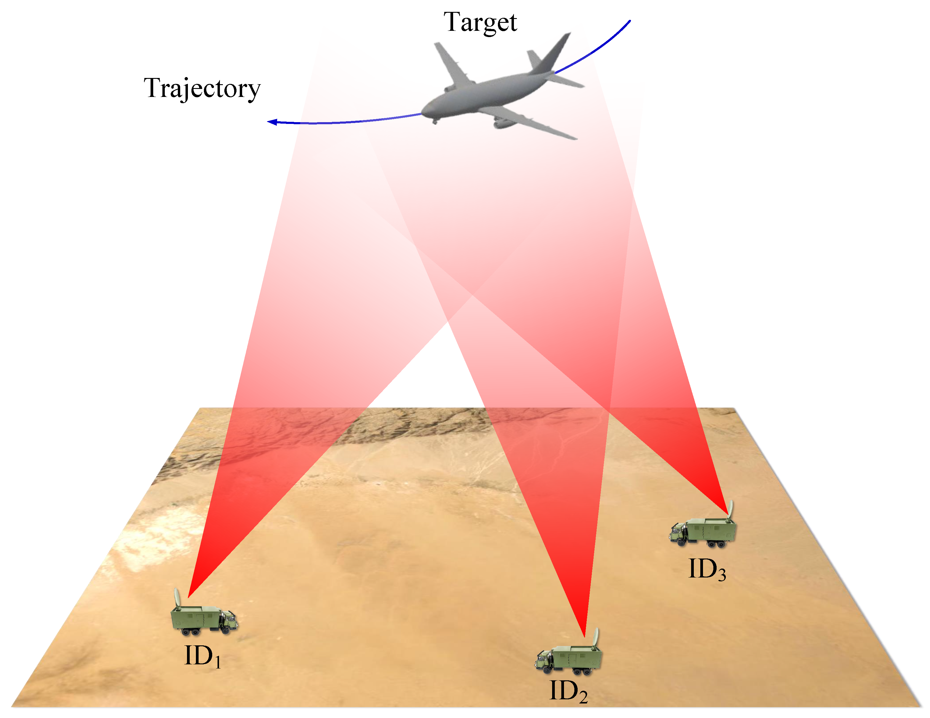
In practical applications, multi-view ISAR can be used for the detection and imaging of airborne targets such as aircraft. Figure 1 shows a typical multi-view ISAR imaging model.
The radars emit Frequency-Modulated Continuous Waves (FMCW) to illuminate the target and the electromagnetic (EM) waves are received and collected by the radar after reflection on the target surface. The signal emitted by the radars is expressed in the following form:
where denotes the signal transmitted by the i-th radar, and K denote the amplitude and chirp rate of the transmit signal, and is the carrier frequency. Further, the baseband signal of the i-th radar signal backscattered from the whole scenarios can be expressed as:
where is the scatterer located at in the coordinate system, is the backscattering coefficient of , is the distance between the point and the radar, c is the speed of light, and f is the frequency.
Assuming that the radar achieves range alignment and phase adjustment by processing the echo signal after range compression, the target can be regarded as a rotation model around the center, O. In this model, can be expressed as:
where is the initial distance between the radar and the center, O, and is the rotational speed of the target. In fact, in a short correlation processing time (CPI), the angular velocity of the target can be regarded as a constant. In combination with Equation (3), Equation (2) can be rewritten as:
where and are independent variables relating to time variable t. The components of the frequency are:
Generally, signal can be regarded as a function of f and in polar coordinates, where . Based on the conversion relationship between the polar coordinate system and the Cartesian coordinate system, the expression of signal in the Cartesian coordinate can be obtained through interpolation operation. Therefore, the target ISAR image can be obtained by taking the two-dimension Inverse Fourier Transform of the signal .
2.2. Problem Description
Equation (6) gives the mathematical model of the target in different radar systems. The image generated by each radar contains only information about a single angle of the target, and the global characteristics of the target are not available. This will bring more challenges to the subsequent recognition tasks. Therefore, after obtaining the target image using the multistatic ISAR system, we need to solve the following three problems:
- a.
- Realize radar image registration. Each radar has a different spatial position relative to the target, which leads to coordinate deviations of the same scattering point in different radar systems, making it unfavorable for image fusion. The angular difference between each radar system and the geometric center of the target is the main cause of image mismatch, which inspires us to estimate the pinch angle and achieve image registration by rotational transformation.
- b.
- Achieve image fusion. After finishing the image alignment, the scattered points in each image are largely aligned, but there are still pixel-level errors. We can use a feature point matching algorithm, such as Speeded Up Robust Features (SURF), to extract the feature points in the images and fuse them. Thus, images containing multi-view information about the target are generated.
- c.
- The generated fusion image contains ISAR image characteristics such as discrete scattering points, clear edge contours, and simple image structure. Therefore, we construct a novel CNN that has a better ability to perceive shallow contours and extract deep features of images.
3. The Proposed Method
To improve the accuracy of ISAR image recognition, we propose a recognition method called MVFRnet with the joint registration fusion module and recognition network. Figure 2 and Algorithm 1 show the overall structure and the algorithm flow, respectively.
3.1. Multi-View Registration Fusion Module
3.1.1. Image Registration
The multistatic radar images can achieve space registration after the spatial matching algorithm. The expression of the matched image is as follows:
where is the i-th radar image after rotation and is a rotation matrix function with respect to the angle . However, there is still a pixel-level error in the registered images, so we use the SURF [46] algorithm to further reduce the error.
- (1)
- Integral map
In the SURF algorithm, the integral map is used to calculate the sum of pixels in a region more efficiently. The integral map is calculated as follows:
where represents the pixel value of point and represents the sum of the pixel value in a rectangular area with and as vertices. Therefore, the sum of pixels in a region can be calculated using only four points.
- (2)
- Hessian Matrix
The Hessian matrix serves to filter out the locations of blob-like structures in the image as possible feature points. For image , the Hessian matrix expression for its point is:
The point is a possible feature point of the image when the determinant of achieves a local maximum. Generally, Gaussians are optimal for scale–space analysis [47,48]. The Hessian matrix combined with Gaussian filtering can be expressed as:
The coefficients in the Gaussian convolution kernel obey a two-dimensional normal distribution, with the weighted values decreasing from the center to the surroundings. When the size of the kernel is large, the operation rate will drop significantly. Box filters are employed to replace the second-order Gaussian kernels to improve the efficiency of the operation. Assuming that the box filters are of size , are the outputs of the convolution of I with box filters ; the approximate output of the determinant is:
where is a weighting factor to reduce the error caused by the introduction of the box filter. Its value is related to the variance of the Gaussian filter and the size of the convolution kernel and is expressed as follows:
where is the 2-norm.
- (3)
- Extraction and matching of feature points
Each pixel point processed by the Hessian matrix is compared with its 26 neighboring points in the two-dimensional image and scale space to locate the feature points. Then, in the circular neighborhood of the feature points, the sum of the Haar wavelets of the equidistant sectors corresponding to each point is calculated. Finally, the direction of the sector with the largest sum is taken as the principal direction of the feature point. After finding all feature points in the two pictures, the matching matrix can be constructed to calibrate the images further. The smaller the Euclidean distance between corresponding points, the better the match.
Assuming that the i-th radar echo data is , the spatially matched image is obtained by rotation transformation. At this point, there is still a pixel-level error in the position of the key points in the images, and further correction is required. By the SURF algorithm, the feature points of the two images are solved and the matching matrix is calculated. The map of picture is multiplied with to obtain the finely matched image . The expression is as follows:
3.1.2. Image Fusion
Common fusion methods for pixel-level images include the maximum value method, weighted average method, principal component analysis (PCA), etc. Considering the computer processing speed and the quality of the fused images, we adopt the weighted average method for the fusion of the matched images. Assuming that there are N images, , to be fused, the expression of the output image after the weighted average is as follows:
where is the weight corresponding to the image .
| Algorithm 1: Multi-View Signal Registration and Fusion | |
| Input: Received echo data , , ..., | |
| Output: Fusion picture | |
| 1 | Processing signal for range alignment and phase adjustment; |
| 2 | Obtaining the spatial matched ISAR images of each radar echo in the xoy coordinate by using Equations (6) and (7); |
| 3 | Constructing integral maps and box filters, extracting each spatial matched image feature point, and using Equation (15) to achieve fine matched of images; |
| 4 | Obtaining fused image ; |
| 5 | return . |
3.2. Recognition Network
Suppose there exist two sets, and , where is the set of features of the sample and is the set of categories. Then, the goal of an identification problem is to find a mapping rule satisfying that there is one and only one , such that .
For radar images, we use neural networks to construct mapping rules f. For a given input ISAR image , is the recognition category. The shallow feature map of the image has a small field of perception, so we add the GCT attention mechanism to enhance the network’s ability to perceive the target contour information. Inspired by the skip block, we add Skip Connect Unit to the deep feature map to prevent network degradation [49].
Based on the above ideas, we construct a novel CNN with a joint GCT attention mechanism and Skip Connect Unit. Figure 3 shows the structure of the network.
- (1)
- GCT attention module
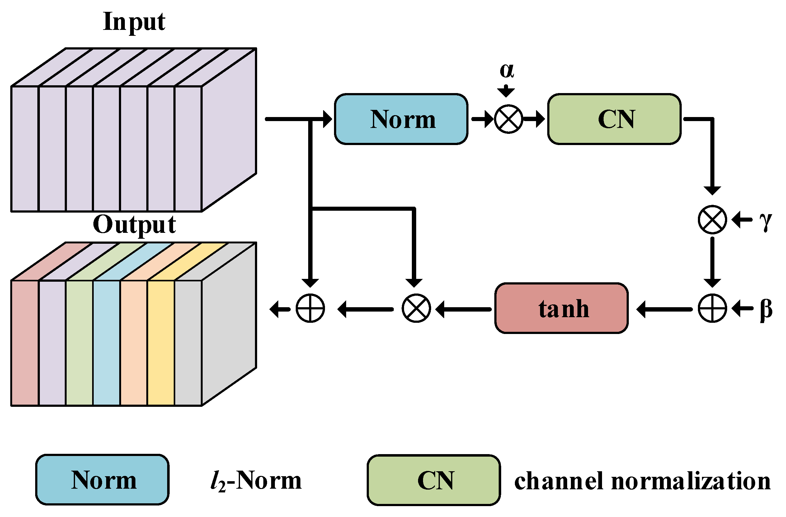
The attention mechanism adaptively weights the features according to the importance of the input to improve the network performance [50,51,52,53]. The GCT attention module first calculates the norm of each channel of the input feature map. The result is multiplied with the learnable parameter to weigh the channels. Afterward, a weighting vector and a bias are applied to the normalized channel to control the cooperation or competition between the channels. The network structure is as Figure 4.
Using for norm, for channel-wise normalization, and for tanh activation function, the mathematical model of GCT can be written as:
where is the input featrue map and denotes the output.
- (2)
- Skip Connect Unit
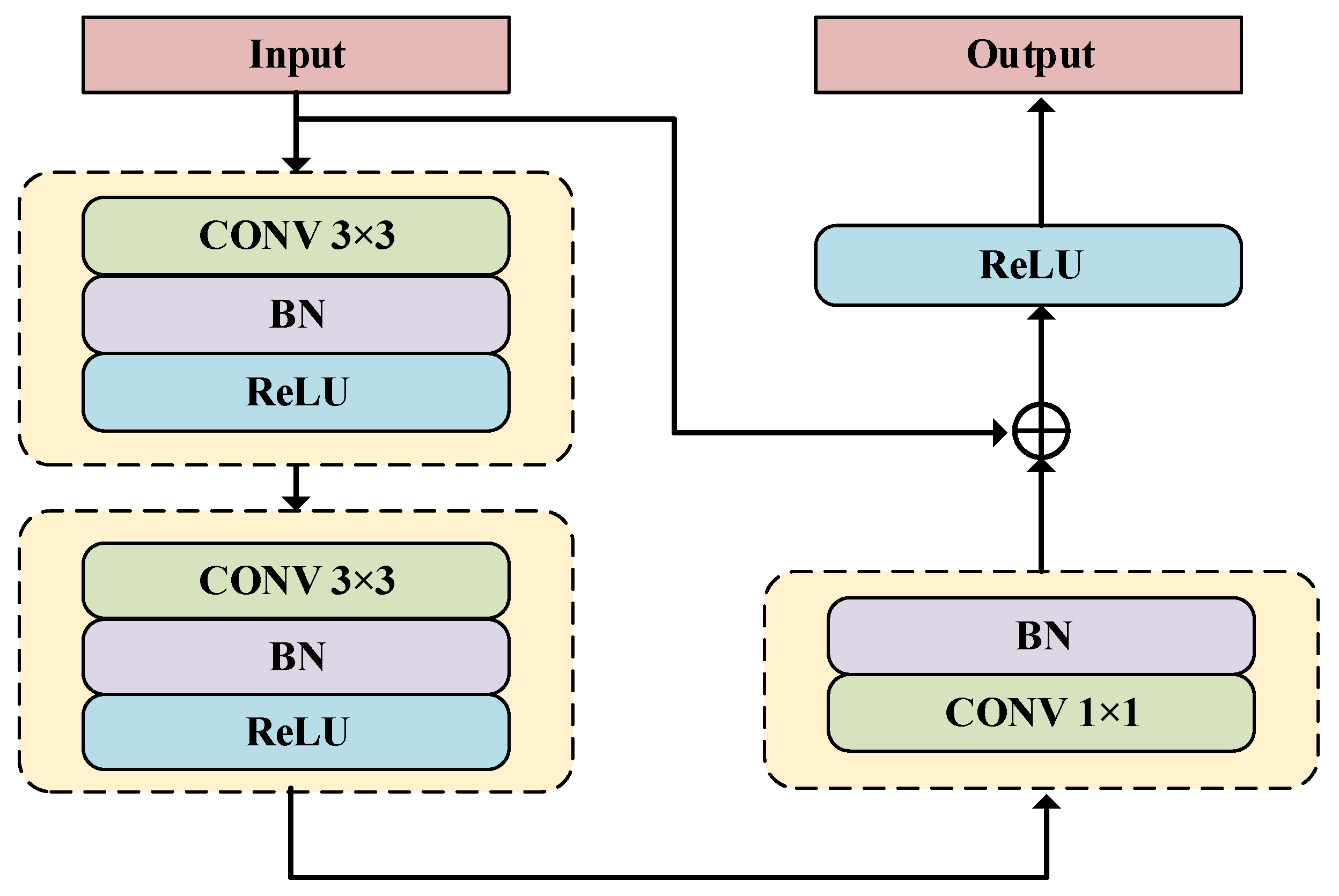
The Skip Connect Unit performs a non-linear operation on the input data and then adds it linearly to the original data as the output. The non-linear operation is used to acquire deep semantic information about the image, while linear summation prevents gradient disappearance. The non-linear operations consist of three convolutions, three normalization operations, and three activation layers. The mathematical expression is as follows.
where is non-linear variation, represents the input, and donetes the output. In this network, the Skip Connect Unit is designed as Figure 5.
- (3)
- Output
In our CNN, 5 convolution blocks, 3 GCT modules, and 3 SCUs are included, totaling 22 layers of convolution. The recognition results are as follows.
where performs a multichannel dimensional transformation of the input image to characterize more image information, BG consists of two blocks and three GCT modules, and BS consists of three blocks and three SCUs. is the predicted value of N categories and is the final prediction.
4. Experiments and Results
Compared with traditional ISAR image recognition, the method proposed in this paper is improved in two aspects. One is the input sample set, and the other is the identification network. We further processed the traditional single-view radar data into fused images and built a novel CNN.
4.1. Simulated Data
4.1.1. Data Construction
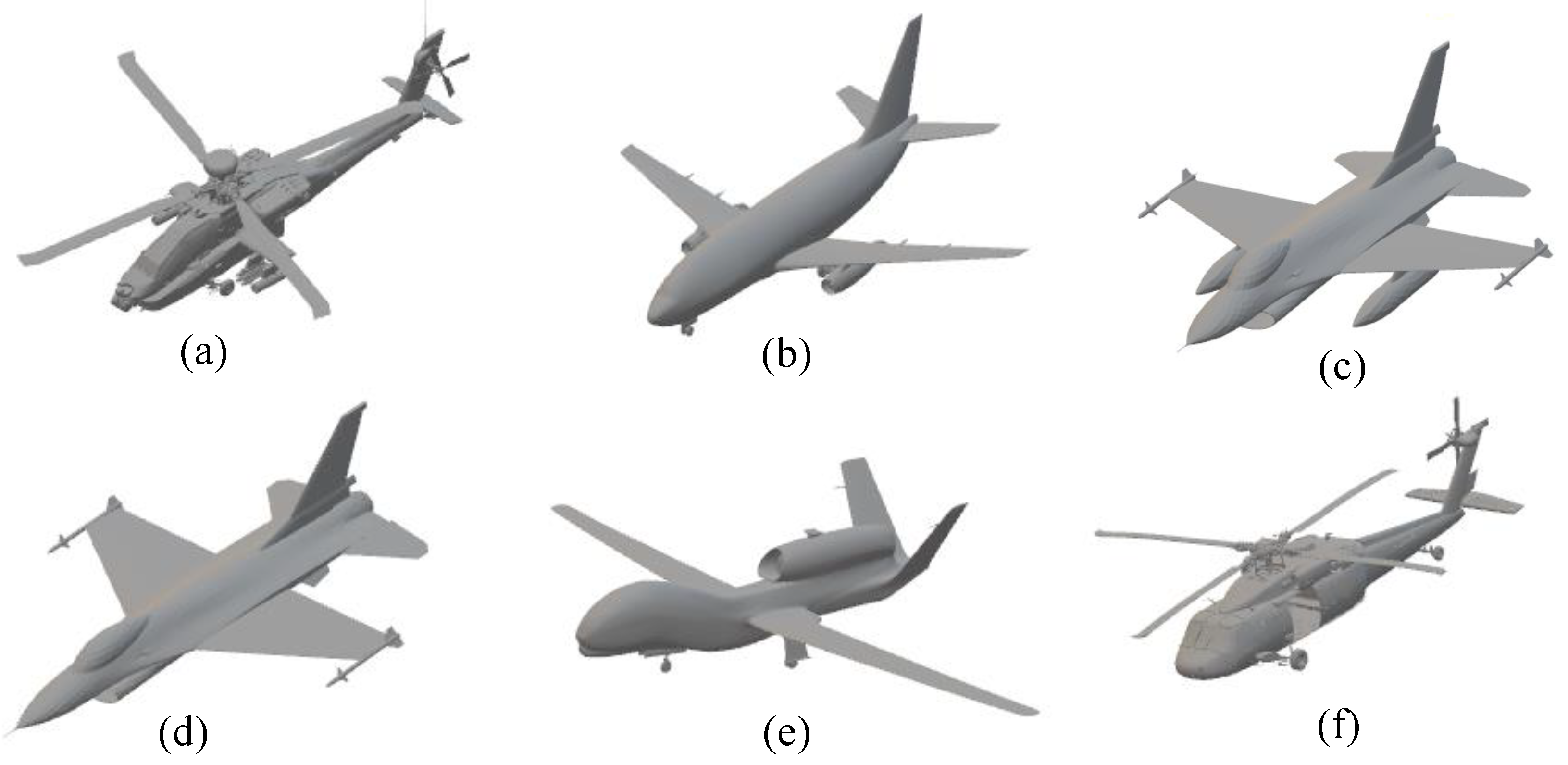
To verify the rationality and feasibility of the proposed method, we utilize electromagnetic simulation software to obtain the data of six aircraft models: an armed helicopter, a passenger plane, a fighter, a fighter without flue tanks, a UAV, and a universal helicopter, which we name as models a, b, c, d, e, f. The geometry of each aircraft is 14.6 m × 17.7 m (a), 28.9 m × 36.5 m (b), 9.9 m × 15.1 m (c,d), 39.9 m × 14.5 m (e), and 16.4 m × 19.8 m (f), respectively. The radar emits FMCW with a carrier frequency of 10 GHz, and a bandwidth of 1.5 GHz. A set of radar data is obtained for every 10 degrees of target rotation around the center. Figure 6 shows the simulated aircraft models and Table 1 lists the experimental parameters.
For an aircraft model, radar observes from seven-pitch angles: = , , , , , , and , respectively. There are 72 azimuth angles, with sampling interval from to . Five-hundred four ISAR images can be obtained for each aircraft model. In conventional ISAR image recognition, the inputs are random single-angle radar images. For MVFRnet, fused images are served as an intermediate layer and input to the recognition network. In this simulation experiment, MVFRnet fuses the five-angle echo data of the target for recognition. Meanwhile, noise is added to the generated images to simulate noise interference in real applications. The following are the four datasets used for the experiments.
Dataset_1: From each aircraft model image, 80% were randomly selected for training and the rest for evaluation, resulting in a training and evaluation set with sample sizes of and .
Dataset_2: Taking into account the effect of noise, we added Gaussian white noise to dataset_1. The peak SNR for the training and evaluation sets are 20 and 15 dB, respectively.
Dataset_3: For each aircraft model, five different angles are randomly selected from the original images in the same pitch angle for fusion, and repeated 72 times for each pitch angle to obtain a total of synthetic images. Eventually, a set of size is generated. Eighty percent of the images are randomly selected as input to the recognition network in MVFRnet, and the remainder serve as the evaluation set.
Dataset_4: In the above dataset, Gaussian white noise is added to result in a peak SNR of 20 dB in the training set and 15 dB in the evaluation set.
4.1.2. Recognition Result
In this experiment, we train four separate datasets using the traditional recognition methods and the MVFRnet and analyze these training models. In our experimental evaluation, we examine the effectiveness and convergence of the networks using Accuracy (), Precision (), and loss function. They are explained as follows.
where TP, , , and represent positive samples judged as positive, negative samples judged as negative, negative samples judged as positive, and positive samples judged as negative, respectively. is the cross-entropy loss function. The value of is 1 if the category of sample i is j, otherwise the value is 0. is the probability that sample i is judged to be of category j. N is the total number of samples.
Figure 9 shows the curve of the loss function with respect to training epochs in the presence and absence of noise, respectively. By analyzing the image data, we conclude that (1) our proposed multi-view fusion model has a better recognition rate compared to traditional methods, and it still has a lower loss value in a low SNR environment. This is because the multi-view fused image has more information and is more stable in the structure; (2) compared with traditional methods, the loss function of our algorithm decreases faster and has a smaller value when it is stable. This is because ISAR images often only contain target contours composed of discrete points, so the GCT attention mechanism can enhance the network’s ability to extract information from the points.
Compared to traditional methods, the MVFRnet we propose greatly improves the recognition rate of images under the same dataset. This is due to the fact that MVFRnet can fuse multi-view images and better extract the contour information. Model c carries the fuel tank based on model d. The rest of the model is the same. When the aircraft is at a specific angle, the radar cannot receive the reflected echo signal from the fuel tank, or the signal is weak, thus the single-angle ISAR images of c and d cannot be distinguished. Therefore, the identification rate of traditional methods, which are insensitive to the shallow contour information of images, is even low. Table 2 and Table 3 give the correct rates for different methods, and the optimal results are bolded. Ultimately, we can conclude that: (1) the MVFRnet jointing fused images and CNN has the highest recognition rate. (2) in the presence of noise, there is only a small reduction in the recognition rate of MVFRnet, due to the fact that the fused images are more stable and less affected by noise and the proposed network is more generalizable.
4.2. Ground-Based MMW Radar Experiment Data
To further validate the effectiveness of the proposed method, an aircraft model is exploited as the target to build a near-field bistatic radar experimental scenario.
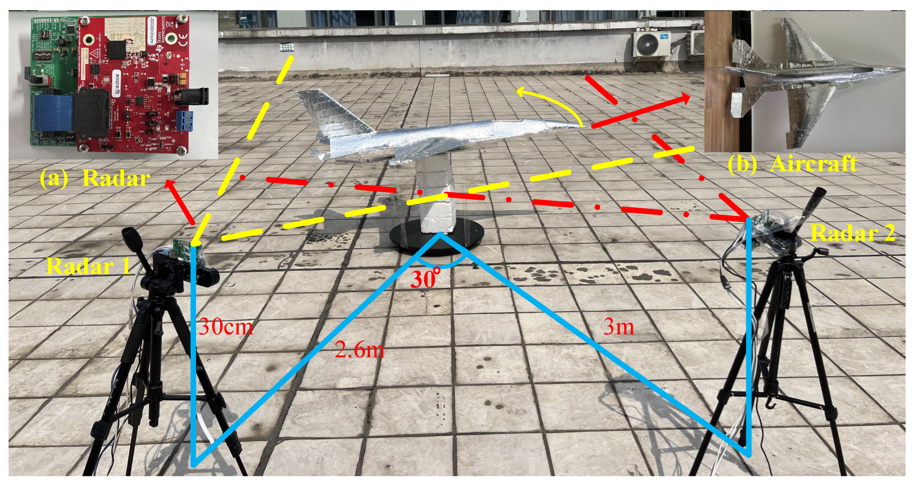
The experiment contains three main parts: the MMW radio frequency (RF) module, the model aircraft, and the image processing module. The radar module includes two TI AWR 2243 evaluation boosts and two DCA1000 data acquisition cards. The configuration parameters of the experiment are shown in Table 4.
The imaging scenario is shown in Figure 10. Radars 1 and 2 are equipped on tripods. The distances from radars 1 and 2 to the center of the turntable are 2.6 m and 3 m, respectively, with an angle of 30. The model airplane has a length of 2.2 m and a wingspan of 2.1 m, is pasted with tinfoil, and rotates with the turntable. Both radars and target height are 30 cm. The turntable speed is 60 s/rad and the radar sampling time is 60 s.
During the radar sampling time, the target is rotated around the center. For every of aircraft rotation, an ISAR image is obtained by employing Equation (6). Seventy-two images are generated utilizing the echo data from Radars 1 and 2, respectively. Figure 11 shows 16 ISAR images from Radars 1 and 2.
Affected by the scattering characteristics of the target at different angles, some single-view ISAR images can hardly reflect the target outline. In this experiment, the tail of the model has a much higher ability to reflect electromagnetic waves than the rest of the model. When the radar beams directly at the tail of the aircraft, the generated 2D image contains only a strong scattering point. As the radar illuminates the side of the target, the generated image has only the outline of one side of the target. Both of these images are not conducive to target identification. A single-view ISAR image with a complete outline of the aircraft can be obtained only when the radar transmits signals directly to the head of the aircraft. The generated single-view ISAR images will be employed as the input of the conventional recognition algorithm.
In ISAR imaging, the target speed needs to be estimated, which affects the image quality and thus the recognition accuracy. To test the generalizability of this method, we add a 10% bias to the rotational speed to simulate the estimation error and generate fused images. In addition, the angle and distance of the multistatic radars to the target are not fixed. Therefore, we change the experimental scene configuration. The angle between the radars and the target is set to and the distance is unified to 3 m. Finally, the above two sets of data are evaluated separately with the trained MVFRnet to further verify the network generalization.
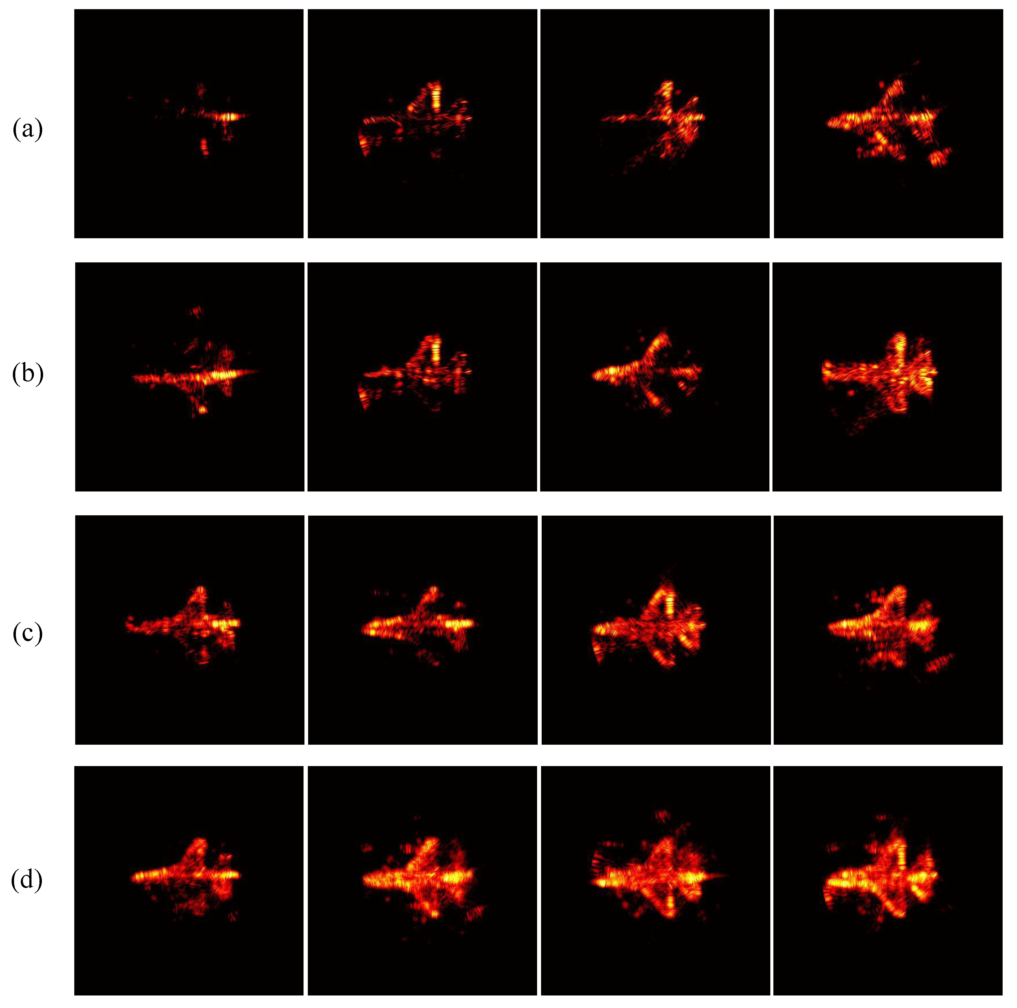
In MVFRnet, multi-view fusion images are input to the recognition network as an intermediate layer. The fused images can be obtained by applying Equation (16) to the echo data from different views of the target. Due to the experimental conditions, only echo data from two views of the target can be collected at the same time, and N-angle image fusion cannot be achieved. Therefore, we select the echoes from N different views to simulate N base station radar to achieve image fusion. Further, to explore the effect of the number of fused views on recognition, let , obtain different intermediate layers. Figure 12 shows the N-view fusion images.
Compared with the single-view ISAR images, the multi-view fusion images have sharper target contours. As the value of N is taken to increase, the blurred aircraft images in the dataset are reduced and the structure of the images is more stable. This is due to the increase in fusion angle, which enhances the information of the image, and the contour of the target is more complete.
The single-view and multi-view fused images generated by Radars 1 and 2 are added to Dataset_1 and Dataset_3, respectively, to validate our method. Table 5 shows the recognition accuracy of the MMW radar experiment data combined with MVFRnet and traditional methods. The data in parentheses are the recognition accuracy of the images in the presence of rotational speed errors and the images of different experimental systems. Table 6 shows the recognition rates for different numbers of fused views.
Observing the data in Table 5 and Table 6, the following conclusions can be drawn: (1) MVFRnet still has a higher accuracy compared to the conventional methods when recognizing the actual targets. This is because MVFRnet fuses the target data to improve the amount of image information and the recognition network has a better perception of image details. (2) If there is an estimation error in the rotational speed of the target, it will affect the quality of the generated images, but the network still has a high recognition accuracy. The data under different experimental systems also have high identification correctness. This indicates the high generalization of the proposed method. (3) The recognition rate of MVFRnet increases with the number of fused views, but the growth rate decreases. This is due to the saturation of information in a single image, which cannot provide more details.
5. Conclusions
In this paper, to improve the recognition accuracy of ISAR images of airborne targets, we propose a recognition method that is used in conjunction with the image registration fusion module and recognition network. Firstly, the ISAR echo data of the same target, with different angles, are input to the multi-view registration fusion module, and the fused images are output. The recognition network we built and traditional methods are then trained using the fused image and the original image, respectively. Comparing the results of different methods, it can be seen that MVFRnet has a higher recognition accuracy and generalizability. This is because the ISAR fusion image structure is more stable, and combining the Skip Connect Unit with the GCT attention mechanism can better preserve the shallow network information and obtain discrete profile information. Finally, we collect real data to verify the effectiveness and accuracy of the proposed scheme. The final results show that the MVFRnet can maximize the recognition accuracy of ISAR images. In future work, we will combine the proposed recognition method with advanced 3D imaging algorithms to further improve the identification accuracy of moving targets.
Author Contributions
Conceptualization, Y.W. and X.L.; methodology, X.L. and Y.W.; software, Y.W. and J.R.; validation, X.L. and Y.W.; formal analysis, J.R. and X.L.; investigation, Y.W.; resources, S.W.; data curation, J.R.; writing—original draft preparation, Y.W.; writing—review and editing, Y.W.; visualization, Y.W. and W.Y.; supervision, X.L.; project administration, X.L.; funding acquisition, X.L. All authors have read and agreed to the published version of the manuscript.
Funding
This work was supported by the National Natural Science Foundation of China (No. 62271108).
Data Availability Statement
Not applicable.
Acknowledgments
The authors would like to thank the anonymous reviewers and editors for their selfless help to improve our manuscript.
Conflicts of Interest
The authors declare no conflict of interest.
References
- Chen, V.C.; Martorella, M. Inverse Synthetic Aperture Radar Imaging; SciTech Publishing: Chennai, India, 2014. [Google Scholar]
- Chen, C.C.; Andrews, H.C. Target-Motion-Induced Radar Imaging. IEEE Trans. Aerosp. Electron. Syst. 1980, AES-16, 2–14. [Google Scholar] [CrossRef]
- Xi, L.; Guosui, L.; Ni, J. Autofocusing of ISAR images based on entropy minimization. IEEE Trans. Aerosp. Electron. Syst. 1999, 35, 1240–1252. [Google Scholar] [CrossRef]
- Berizzi, F.; Corsini, G. Focusing of Two Dimensional ISAR Images by Contrast Maximization. In Proceedings of the 1992 22nd European Microwave Conference, Helsinki, Finland, 5–9 September 1992; Volume 2, pp. 951–956. [Google Scholar] [CrossRef]
- Xu, G.; Zhang, B.; Yu, H.; Chen, J.; Xing, M.; Hong, W. Sparse Synthetic Aperture Radar Imaging From Compressed Sensing and Machine Learning: Theories, applications, and trends. IEEE Geosci. Remote Sens. Mag. 2022, 10, 32–69. [Google Scholar] [CrossRef]
- Xu, G.; Zhang, B.; Chen, J.; Hong, W. Structured Low-Rank and Sparse Method for ISAR Imaging with 2-D Compressive Sampling. IEEE Trans. Geosci. Remote Sens. 2022, 60, 5239014. [Google Scholar] [CrossRef]
- Xu, G.; Zhang, B.; Chen, J.; Wu, F.; Sheng, J.; Hong, W. Sparse Inverse Synthetic Aperture Radar Imaging Using Structured Low-Rank Method. IEEE Trans. Geosci. Remote Sens. 2022, 60, 1–12. [Google Scholar] [CrossRef]
- Qu, Q.; Wei, S.; Wu, Y.; Wang, M. ACSE Networks and Autocorrelation Features for PRI Modulation Recognition. IEEE Commun. Lett. 2020, 24, 1729–1733. [Google Scholar] [CrossRef]
- Wei, S.; Qu, Q.; Wu, Y.; Wang, M.; Shi, J. PRI Modulation Recognition Based on Squeeze-and-Excitation Networks. IEEE Commun. Lett. 2020, 24, 1047–1051. [Google Scholar] [CrossRef]
- Qu, Q.; Wei, S.; Su, H.; Wang, M.; Shi, J.; Hao, X. Radar Signal Recognition Based on Squeeze-and-Excitation Networks. In Proceedings of the 2019 IEEE International Conference on Signal, Information and Data Processing (ICSIDP), Chongqing, China, 11–13 December 2019; pp. 1–5. [Google Scholar] [CrossRef]
- Yang, R.; Hu, Z.; Liu, Y.; Xu, Z. A Novel Polarimetric SAR Classification Method Integrating Pixel-Based and Patch-Based Classification. IEEE Geosci. Remote Sens. Lett. 2020, 17, 431–435. [Google Scholar] [CrossRef]
- Chen, S.; Wang, H.; Xu, F.; Jin, Y.Q. Target Classification Using the Deep Convolutional Networks for SAR Images. IEEE Trans. Geosci. Remote Sens. 2016, 54, 4806–4817. [Google Scholar] [CrossRef]
- Raj, J.A.; Idicula, S.M.; Paul, B. One-Shot Learning-Based SAR Ship Classification Using New Hybrid Siamese Network. IEEE Geosci. Remote Sens. Lett. 2022, 19, 4017205. [Google Scholar] [CrossRef]
- Li, L.; Wang, C.; Zhang, H.; Zhang, B. SAR Image Ship Object Generation and Classification with Improved Residual Conditional Generative Adversarial Network. IEEE Geosci. Remote Sens. Lett. 2022, 19, 4000105. [Google Scholar] [CrossRef]
- Wei, S.; Liang, J.; Wang, M.; Shi, J.; Zhang, X.; Ran, J. AF-AMPNet: A Deep Learning Approach for Sparse Aperture ISAR Imaging and Autofocusing. IEEE Trans. Geosci. Remote Sens. 2022, 60, 5206514. [Google Scholar] [CrossRef]
- Yang, Y.; Gao, X.; Shen, Q. Learning Embedding Adaptation for ISAR Image Recognition with Few Samples. In Proceedings of the 2021 2nd Information Communication Technologies Conference (ICTC), Nanjing, China, 7–9 May 2021; pp. 86–89. [Google Scholar] [CrossRef]
- Ma, F.; He, Y.; Li, Y. Comparison of aircraft target recognition methods based on ISAR images. In Proceedings of the 2022 IEEE 10th Joint International Information Technology and Artificial Intelligence Conference (ITAIC), Chongqing, China, 17–19 June 2022; Volume 10, pp. 1291–1295. [Google Scholar] [CrossRef]
- Toumi, A.; Khenchaf, A. Target recognition using IFFT and MUSIC ISAR images. In Proceedings of the 2016 2nd International Conference on Advanced Technologies for Signal and Image Processing (ATSIP), Monastir, Tunisia, 21–23 March 2016; pp. 596–600. [Google Scholar] [CrossRef]
- Cai, H.; He, Q.; Han, Z.; Shang, C. ISAR target recognition based on manifold learning. In Proceedings of the 2009 IET International Radar Conference, Guilin, China, 20–22 April 2009; pp. 1–4. [Google Scholar] [CrossRef]
- Wang, L.; Zhu, D.; Zhu, Z. Cross-range scaling for aircraft ISAR images based on axis slope measurements. In Proceedings of the 2008 IEEE Radar Conference, Rome, Italy, 26–30 May 2008; pp. 1–6. [Google Scholar] [CrossRef]
- Chen, V.; Lipps, R.; Bottoms, M. Advanced synthetic aperture radar imaging and feature analysis. In Proceedings of the International Conference on Radar (IEEE Cat. No; pp. 03EX695), Adelaide, SA, Australia, 3–5 September 2003; pp. 22–29. [Google Scholar] [CrossRef]
- El Housseini, A.; Toumi, A.; Khenchaf, A. Deep Learning for target recognition from SAR images. In Proceedings of the 2017 Seminar on Detection Systems Architectures and Technologies (DAT), Algiers, Algeria, 20–22 February 2017; pp. 1–5. [Google Scholar] [CrossRef]
- Park, J.I.; Kim, K.T. A Comparative Study on ISAR Imaging Algorithms for Radar Target Identification. Prog. Electromagn. Res. 2010, 108, 155–175. [Google Scholar] [CrossRef] [Green Version]
- Musman, S.; Kerr, D.; Bachmann, C. Automatic recognition of ISAR ship images. IEEE Trans. Aerosp. Electron. Syst. 1996, 32, 1392–1404. [Google Scholar] [CrossRef] [Green Version]
- Kurowska, A.; Kulpa, J.S.; Giusti, E.; Conti, M. Classification results of ISAR sea targets based on their two features. In Proceedings of the 2017 Signal Processing Symposium (SPSympo), Jachranka, Poland, 12–14 September 2017; pp. 1–6. [Google Scholar] [CrossRef]
- Kim, K.T.; Seo, D.K.; Kim, H.T. Efficient classification of ISAR images. IEEE Trans. Antennas Propag. 2005, 53, 1611–1621. [Google Scholar] [CrossRef]
- Yuankui, H.; Yiming, Y. Automatic target recognition of ISAR images based on Hausdorff distance. In Proceedings of the 2007 1st Asian and Pacific Conference on Synthetic Aperture Radar, Huangshan, China, 5–9 November 2007; pp. 477–479. [Google Scholar] [CrossRef]
- Kumar, A.; Giusti, E.; Mancuso, F.; Ghio, S.; Lupidi, A.; Martorella, M. Three-Dimensional Polarimetric InISAR Imaging of Non-Cooperative Targets. IEEE Trans. Comput. Imaging 2023, 9, 210–223. [Google Scholar] [CrossRef]
- Giusti, E.; Kumar, A.; Mancuso, F.; Ghio, S.; Martorella, M. Fully polarimetric multi-aspect 3D InISAR. In Proceedings of the 2022 23rd International Radar Symposium (IRS), Gdansk, Poland, 12–14 September 2022; pp. 184–189. [Google Scholar] [CrossRef]
- Park, J.; Raj, R.G.; Martorella, M.; Giusti, E. Simulation and Analysis of 3-D Polarimetric Interferometric ISAR Imaging. In Proceedings of the IGARSS 2022—2022 IEEE International Geoscience and Remote Sensing Symposium, Kuala Lumpur, Malaysia, 17–22 July 2022; pp. 2023–2026. [Google Scholar] [CrossRef]
- Qu, Q.; Wei, S.; Liu, S.; Liang, J.; Shi, J. JRNet: Jamming Recognition Networks for Radar Compound Suppression Jamming Signals. IEEE Trans. Veh. Technol. 2020, 69, 15035–15045. [Google Scholar] [CrossRef]
- Wang, M.; Wei, S.; Liang, J.; Zeng, X.; Wang, C.; Shi, J.; Zhang, X. RMIST-Net: Joint Range Migration and Sparse Reconstruction Network for 3-D mmW Imaging. IEEE Trans. Geosci. Remote Sens. 2022, 60, 1–17. [Google Scholar] [CrossRef]
- Wei, S.; Zhang, H.; Zeng, X.; Zhou, Z.; Shi, J.; Zhang, X. CARNet: An effective method for SAR image interference suppression. Int. J. Appl. Earth Obs. Geoinf. 2022, 114, 103019. [Google Scholar] [CrossRef]
- Wang, M.; Wei, S.; Liang, J.; Zhou, Z.; Qu, Q.; Shi, J.; Zhang, X. TPSSI-Net: Fast and Enhanced Two-Path Iterative Network for 3D SAR Sparse Imaging. IEEE Trans. Image Process. 2021, 30, 7317–7332. [Google Scholar] [CrossRef]
- Wang, M.; Wei, S.; Shi, J.; Wu, Y.; Qu, Q.; Zhou, Y.; Zeng, X.; Tian, B. CSR-Net: A Novel Complex-Valued Network for Fast and Precise 3-D Microwave Sparse Reconstruction. IEEE J. Sel. Top. Appl. Earth Obs. Remote Sens. 2020, 13, 4476–4492. [Google Scholar] [CrossRef]
- Dung, P.T. Combined neural networks for radar target recognition from radar range profiles. In Proceedings of the 2008 International Conference on Advanced Technologies for Communications, Hanoi, Vietnam, 6–9 October 2008; pp. 353–355. [Google Scholar] [CrossRef]
- Li, G.; Sun, Z.; Zhang, Y. ISAR Target Recognition Using Pix2pix Network Derived from cGAN. In Proceedings of the 2019 International Radar Conference (RADAR), Toulon, France, 23–27 September 2019; pp. 1–4. [Google Scholar] [CrossRef]
- Xue, B.; Tong, N. Real-World ISAR Object Recognition Using Deep Multimodal Relation Learning. IEEE Trans. Cybern. 2020, 50, 4256–4267. [Google Scholar] [CrossRef] [PubMed]
- Zhao, W.; Heng, A.; Rosenberg, L.; Nguyen, S.T.; Hamey, L.; Orgun, M. ISAR Ship Classification Using Transfer Learning. In Proceedings of the 2022 IEEE Radar Conference (RadarConf22), New York, NY, USA, 21–25 March 2022; pp. 1–6. [Google Scholar] [CrossRef]
- Li, Z.; Narayanan, R.M. Data Level Fusion of Multilook Inverse Synthetic Aperture Radar (ISAR) Images. In Proceedings of the 35th IEEE Applied Imagery and Pattern Recognition Workshop (AIPR’06), Washington, DC, USA, 11–13 October 2006; p. 2. [Google Scholar] [CrossRef]
- Ram, S.S. Fusion of Inverse Synthetic Aperture Radar and Camera Images for Automotive Target Tracking. IEEE J. Sel. Top. Signal Process. 2022, 1–14. [Google Scholar] [CrossRef]
- Li, Z.; Narayanan, R.M. Cross-band Inverse Synthetic Aperture Radar (ISAR) Image Fusion. In Proceedings of the 2007 International Symposium on Signals, Systems and Electronics, Montreal, QC, Canada, 30 July–2 August 2007; pp. 111–114. [Google Scholar] [CrossRef]
- Li, Y.; Yang, B.; He, Z.; Chen, R. An ISAR Automatic Target Recognition Approach Based on SBR-based Fast Imaging Scheme and CNN. In Proceedings of the 2020 IEEE MTT-S International Wireless Symposium (IWS), Shanghai, China, 20–23 September 2020; pp. 1–3. [Google Scholar] [CrossRef]
- Lu, W.; Zhang, Y.; Yin, C.; Lin, C.; Xu, C.; Zhang, X. A Deformation Robust ISAR Image Satellite Target Recognition Method Based on PT-CCNN. IEEE Access 2021, 9, 23432–23453. [Google Scholar] [CrossRef]
- Wielgo, M.; Soszka, M.; Rytel-Andrianik, R. Convolutional Neural Network for 3D ISAR Non-Cooperative Target Recognition. In Proceedings of the 2022 23rd International Radar Symposium (IRS), Gdansk, Poland, 12–14 September 2022; pp. 190–195. [Google Scholar] [CrossRef]
- Bay, H.; Ess, A.; Tuytelaars, T.; Van Gool, L. Speeded-Up Robust Features (SURF). Comput. Vis. Image Underst. 2008, 110, 346–359. [Google Scholar] [CrossRef]
- Lindeberg, T. Scale-space for discrete signals. IEEE Trans. Pattern Anal. Mach. Intell. 1990, 12, 234–254. [Google Scholar] [CrossRef] [Green Version]
- Koenderink, J.J. The structure of images. Biol. Cybern. 1984, 50, 363–370. [Google Scholar] [CrossRef]
- Yang, Z.; Zhu, L.; Wu, Y.; Yang, Y. Gated Channel Transformation for Visual Recognition. In Proceedings of the 2020 IEEE/CVF Conference on Computer Vision and Pattern Recognition (CVPR), Seattle, WA, USA, 13–19 June 2020; pp. 11791–11800. [Google Scholar] [CrossRef]
- Hu, J.; Shen, L.; Sun, G. Squeeze-and-Excitation Networks. In Proceedings of the 2018 IEEE/CVF Conference on Computer Vision and Pattern Recognition, Salt Lake City, UT, USA, 18–23 June 2018; pp. 7132–7141. [Google Scholar]
- Lee, H.; Kim, H.E.; Nam, H. SRM: A Style-Based Recalibration Module for Convolutional Neural Networks. In Proceedings of the 2019 IEEE/CVF International Conference on Computer Vision (ICCV), Seoul, Republic of Korea, 27 October–2 November 2019; pp. 1854–1862. [Google Scholar] [CrossRef] [Green Version]
- Wang, Q.; Wu, B.; Zhu, P.; Li, P.; Zuo, W.; Hu, Q. ECA-Net: Efficient Channel Attention for Deep Convolutional Neural Networks. In Proceedings of the 2020 IEEE/CVF Conference on Computer Vision and Pattern Recognition (CVPR), Seattle, WA, USA, 13–19 June 2020; pp. 11531–11539. [Google Scholar] [CrossRef]
- Qin, Z.; Zhang, P.; Wu, F.; Li, X. FcaNet: Frequency Channel Attention Networks. In Proceedings of the 2021 IEEE/CVF International Conference on Computer Vision (ICCV), Montreal, QC, Canada, 10–17 October 2021; pp. 763–772. [Google Scholar] [CrossRef]
Figure 1.
A typical model multi-view ISAR imaging.

Figure 2.
The overall structure of MVFRnet.

Figure 3.
Theoverall structure of CNN we constructed, where the block consists of several convolutions and the output is the identification of the target category.
Figure 3.
Theoverall structure of CNN we constructed, where the block consists of several convolutions and the output is the identification of the target category.

Figure 4.
The overall structure of GCT attention module. Where CN is channel normalization, ⊗ denotes elements multiplication, and ⊕ represents the elements addition.
Figure 4.
The overall structure of GCT attention module. Where CN is channel normalization, ⊗ denotes elements multiplication, and ⊕ represents the elements addition.

Figure 5.
The Skip Connect Unit contains three convolutions, three normalization operations, and three ReLU layers.
Figure 5.
The Skip Connect Unit contains three convolutions, three normalization operations, and three ReLU layers.

Figure 6.
Geometric model of aircraft, where (a) is the armed helicopter, (b) is the passenger plane, (c) is the fighter, (d) is the fighter without flue tanks, (e) is the UAV, and (f) is the universal helicopter.
Figure 6.
Geometric model of aircraft, where (a) is the armed helicopter, (b) is the passenger plane, (c) is the fighter, (d) is the fighter without flue tanks, (e) is the UAV, and (f) is the universal helicopter.

Figure 7.
Single-view 2D ISAR images of six aircraft, where (a) is the armed helicopter, (b) is the passenger plane, (c) is the fighter, (d) is the fighter without flue tanks, (e) is the UAV, and (f) is the universal helicopter.
Figure 7.
Single-view 2D ISAR images of six aircraft, where (a) is the armed helicopter, (b) is the passenger plane, (c) is the fighter, (d) is the fighter without flue tanks, (e) is the UAV, and (f) is the universal helicopter.

Figure 8.
Multi-view 2D ISAR fusion images of six aircraft, where (a) is the armed helicopter, (b) is the passenger plane, (c) is the fighter, (d) is the fighter without flue tanks, (e) is the UAV, and (f) is the universal helicopter.
Figure 8.
Multi-view 2D ISAR fusion images of six aircraft, where (a) is the armed helicopter, (b) is the passenger plane, (c) is the fighter, (d) is the fighter without flue tanks, (e) is the UAV, and (f) is the universal helicopter.

Figure 9.
Loss function curves for different methods; (a) has no noise, while (b) has noise.

Figure 10.
MMW turntable imaging platform. (a) The MMW RF module. (b) The optical image of the aircraft.
Figure 10.
MMW turntable imaging platform. (a) The MMW RF module. (b) The optical image of the aircraft.

Figure 11.
Single-view ISAR images. (a) ISAR images of Radar 1. (b) ISAR images of Radar 2.

Figure 12.
N-view fusion ISAR images. (a) 2-view fusion ISAR images. (b) 3-view fusion ISAR images. (c) 5-view fusion ISAR images. (d) 9-view fusion ISAR images.
Figure 12.
N-view fusion ISAR images. (a) 2-view fusion ISAR images. (b) 3-view fusion ISAR images. (c) 5-view fusion ISAR images. (d) 9-view fusion ISAR images.


Table 1.
Simulation Parameters.
| Simulation Parameter | Value |
|---|---|
| Radar Center Frequency | 10 GHz |
| Radar Bandwidth | 1.5 GHz |
| Target Rotation Angle | 0–360 |
| Target Range | 20 km |
| Target height | 1–14 km |
Table 2.
Comparison of the Accuracy AP for different aircraft models without noise.
| Method | a-AP | b-AP | c-AP | d-AP | e-AP | f-AP | Acc |
|---|---|---|---|---|---|---|---|
| ResNet34 | 51.25% | 79.28% | 43.45% | 26.68% | 80.77% | 68.35% | 58.30% |
| ResNet50 | 54.76% | 89.12% | 49.87% | 30.41% | 82.30% | 72.07% | 63.13% |
| InceptionNet | 56.66% | 87.12% | 51.01% | 30.98% | 85.30% | 79.57% | 65.11% |
| EfficientNet | 80.86% | 90.32% | 57.76% | 58.32% | 90.47% | 92.37% | 78.35% |
| MVFRnet | 93.53% | 97.76% | 94.32% | 93.89% | 97.60% | 94.64% | 95.29% |
Table 3.
Comparison of the Accuracy AP for different aircraft models with noise.
| Method | a-AP | b-AP | c-AP | d-AP | e-AP | f-AP | Acc |
|---|---|---|---|---|---|---|---|
| ResNet34 | 29.12% | 67.35% | 21.83% | 16.87% | 76.65% | 61.15% | 45.50% |
| ResNet50 | 30.01% | 72.45% | 30.47% | 17.98% | 77.41% | 60.45% | 48.13% |
| InceptionNet | 40.45% | 80.17% | 36.74% | 36.18% | 77.73% | 64.96% | 56.04% |
| EfficientNet | 41.71% | 85.69% | 40.44% | 37.64% | 80.46% | 70.48% | 59.43% |
| MVFRnet | 90.47% | 92.19% | 92.48% | 90.67% | 94.76% | 92.31% | 92.14% |
Table 4.
Experiment Parameters.
| Parameter | Value |
|---|---|
| start frequency | 77 GHz |
| frequency slope | 68.70 MHz/s |
| bandwidth | 3.52 GHz |
| samping rate | 5000 ksps |
| pulse duration | 51.20 s |
| pulse interval | 2 ms |
| Radar 1 distance | 2.6 m |
| Radar 2 distance | 3 m |
| turntable speed | 60 s/rad |
Table 5.
The recognition probability of different methods.
| Model | ResNet34 | ResNet50 | InceptionNet | EfficientNet | MVFRnet (5-View) | |
|---|---|---|---|---|---|---|
| Probability | Radar 1 | |||||
| Radar 2 | ||||||
Table 6.
The recognition probability for different numbers of fused views.
| N-View Fusion | N = 2 | N = 3 | N = 4 | N = 5 | N = 6 | N = 7 | N = 8 | N = 9 |
|---|---|---|---|---|---|---|---|---|
| Probability |
Disclaimer/Publisher’s Note: The statements, opinions and data contained in all publications are solely those of the individual author(s) and contributor(s) and not of MDPI and/or the editor(s). MDPI and/or the editor(s) disclaim responsibility for any injury to people or property resulting from any ideas, methods, instructions or products referred to in the content. |
© 2023 by the authors. Licensee MDPI, Basel, Switzerland. This article is an open access article distributed under the terms and conditions of the Creative Commons Attribution (CC BY) license (https://creativecommons.org/licenses/by/4.0/).
Share and Cite
MDPI and ACS Style
Li, X.; Ran, J.; Wen, Y.; Wei, S.; Yang, W. MVFRnet: A Novel High-Accuracy Network for ISAR Air-Target Recognition via Multi-View Fusion. Remote Sens. 2023, 15, 3052. https://doi.org/10.3390/rs15123052
AMA Style
Li X, Ran J, Wen Y, Wei S, Yang W. MVFRnet: A Novel High-Accuracy Network for ISAR Air-Target Recognition via Multi-View Fusion. Remote Sensing. 2023; 15(12):3052. https://doi.org/10.3390/rs15123052
Chicago/Turabian StyleLi, Xiuhe, Jinhe Ran, Yanbo Wen, Shunjun Wei, and Wei Yang. 2023. "MVFRnet: A Novel High-Accuracy Network for ISAR Air-Target Recognition via Multi-View Fusion" Remote Sensing 15, no. 12: 3052. https://doi.org/10.3390/rs15123052
Note that from the first issue of 2016, this journal uses article numbers instead of page numbers. See further details here.