
Mainlobe Deceptive Jammer Suppression Based on Quadratic Phase Coding in FDA-MIMO Radar


National Key Laboratory of Radar Signal Processing, Xidian University, Xi’an 710071, China
*
Author to whom correspondence should be addressed.
Remote Sens. 2022, 14(22), 5831; https://doi.org/10.3390/rs14225831
Submission received: 25 September 2022
/
Revised: 12 November 2022
/
Accepted: 13 November 2022
/
Published: 17 November 2022
(This article belongs to the Special Issue Small or Moving Target Detection with Advanced Radar System)
Abstract
:In this paper, the problem of mainlobe deceptive jammer suppression is solved with the frequency diversity array-multiple-input multiple-output (FDA-MIMO) radar system. At the modeling stage, based on the FDA-MIMO radar, a quadratic phase code (QPC) is applied along the slow time dimension in the transmit array. In the receiver, after decoding and principal range compensation, the true and false targets that are generated in an identical angle, can be discriminated in the joint transmit-receive-Doppler frequency domain. Particularly, the false targets are equivalently moved from the mainlobe to the sidelobes in the transmit spatial frequency domain. Then, by performing the data-dependent transmit-receive-Doppler three-dimensional beamforming, the false targets are suppressed owing to Doppler and range mismatches. Moreover, by moving the jammers to nulls in the Doppler frequency domain, the capability in terms of the maximum number of suppressible jammers can be strengthened with an appropriate coding coefficient and frequency increment. Numerical results can certify the suppression capability of the QPC-FDA-MIMO radar.
1. Introduction
Radar systems have been widely used in military and civil applications owing to their advantages of detecting targets in all-time and all-whether [1,2]. However, in the complex electromagnetic environment, the jamming signals pose a severe threat to radar systems [3,4]. Among distinct types of jammers, deceptive jammers are generated by intercepting the radar’s waveform and re-transmitting it to fool the victim radars, making it tough to discriminate between false targets and true ones [5]. Particularly, after some appropriate modulations of the digital radio frequency memory (DRFM), the deception is strengthened, and the false targets are produced with parameters such as angle, waveform, and frequency the same as that of the true target [6,7]. The jammers which are situated at the sidelobes of the radar antenna beam can be effectively suppressed via spatial processing methods, such as generalized sidelobe canceller (GSC), ultra-low sidelobe antennas, and space-time adaptive processing (STAP) [8,9]. However, the suppression of mainlobe deceptive jammers is more challenging due to limited degrees-of-freedom (DOFs) to distinguish the true one from the false targets in the angle domain.
At present, methods to suppress mainlobe jammers have been explored by exploiting the discrepancies between the false targets and the true target in various domains, such as the time domain [10], frequency domain [11,12,13], spatial domain [14], and polarization domain [15]. Particularly, pulse frequency agility was utilized in [16] by adopting distinct frequencies among the transmit pulses. However, the coherence among pulses cannot be ensured. Considering the suppression methods in the spatial domain, the methods based on compressed sensing were utilized to reconstruct the echo signal for intermittent sampling jammer [17]. In addition, the projection matrix/blocking matrix was utilized [18,19]. Nevertheless, the projection matrix/blocking matrix is difficult to construct and the methods are sensitive to errors. Moreover, the signal can be separated from the source signal based on the blind source separation [20,21,22]. However, the jammers and target must be independent or less correlated, and additional prior knowledge is required to estimate the number of sources. In [23,24,25], the polarization filter was designed to suppress the jammers. However, some considerable limitations in practice exist when using the aforementioned methods for suppressing the mainlobe deceptive jammers with the characteristics of high density and high fidelity. Thus, it is worth investigating suppression approaches based on novel radar frameworks.
In the decade, the frequency diversity array-multiple-input multiple-output (FDA-MIMO) radar has attracted extensive attention. Unlike the phased array radar, a frequency increment is adopted between all the adjacent elements in the transmit array, and the range-angle-dependent transmit beampattern is generated [26,27,28]. Hence, extra DOFs in the range domain are obtained, and the flexibility in signal processing is improved [29]. To this end, a large number of studies are focused on jammer suppression by utilizing data-dependent and data-independent beamforming methods in the FDA-MIMO radar, where the false targets are suppressed by means of nulling in the joint transmit-receive spatial domain [30,31,32,33,34]. Moreover, the PBN-BF method was utilized to improve the robustness of jammer suppression by broadening the nulls [35]. In addition, similar to FDA-MIMO radar, the suppression of mainlobe deceptive jammers with the Element-Pulse-Coding (EPC)-MIMO radar was investigated [35,36,37]. Moreover, a new technology based on polarization was developed in [38] by jointly utilizing the information including the angle, range, as well as polarization to suppress the jammers. Additionally, a low-rank-low-rank-sparse method was proposed to recover the signal of the target and suppresses the blocking jamming [39]. In [40], an optimization model was established by considering the frequency increments regulation based on non-uniformly spaced FDA radar. However, the maximum number of jammers with such a method equals that of the transmit elements. In other words, the performance of jammer suppression is limited to the system DOFs.
In this paper, to address the issue of mainlobe jammer suppression, a novel coding scheme in FDA-MIMO is suggested. During the modeling phase, a quadratic phase code (QPC) is introduced in the slow time pulses. In this regard, extra DOFs in both range and Doppler domains can be obtained. In the receiver, after decoding and principal range compensation, the true and false targets that locate a couple of pulses behind the true target are discriminated in the joint transmit-receive and Doppler frequency domain. In particular, these false targets are equivalently moved to the sidelobes of the equivalent transmit beam pattern. Furthermore, the data-dependent transmit-receive-Doppler three-dimensional beamforming is developed to suppress the false targets by means of nulling in the transmit-receive-Doppler domain due to range and Doppler mismatches. At the analysis stage, the designs of the coding coefficient and frequency increment are investigated to increase the number of suppressible false targets, where the jammers are moved to the nulls in the beampattern of the Doppler frequency domain. Furthermore, to illustrate the effectiveness of the mentioned suppression method, the simulation results are provided.
In this paper, the structure is given as follows. The QPC-FDA-MIMO radar system’s signal model is provided in Section 2. The principle of main lobe deceptive jammer suppression with the QPC-FDA-MIMO radar is investigated in Section 3. To demonstrate the performance of the developed approaches, the numerical simulations are presented in Section 4. In Section 5, conclusions are drawn.
2. Signal Model of FDA-MIMO Radar
2.1. Transmit Signal Model
A collocated MIMO radar is considered in a uniform linear array with N transmit and M receive elements, where the first element is taken as the reference. A small frequency increment is introduced across the array elements, and the carrier frequency of the m-th element is assigned as
where indicates the reference carrier frequency.
Different from the conventional FDA-MIMO radar, the QPC factor of the k-th pulse is designed as with the coding coefficient. Hence, the signal which is transmitted by the m-th antenna element is:
where denotes the radar pulse duration, is the total energy, , indicates the orthogonal waveform transmitted by the m-th element with the complex envelope
where is the length of the subpulse, is the number of the subpulses, .
2.2. Receive Signal Model
Assume that there is a point-like target in the far-field at angle and range , whose delayed pulse number is . Considering pulses, the coding phase related to the -th () pulse can be expressed as:
The signal that is received by the n-th element is expressed as:
where the approximation holds for the assumption of a narrow band, represents the complex coefficient of the point target. represents the round-trip propagation time delay, represents the common time delay, donates the inter-element spacing. is the Doppler frequency of the target with and , the target speed and wavelength, respectively.
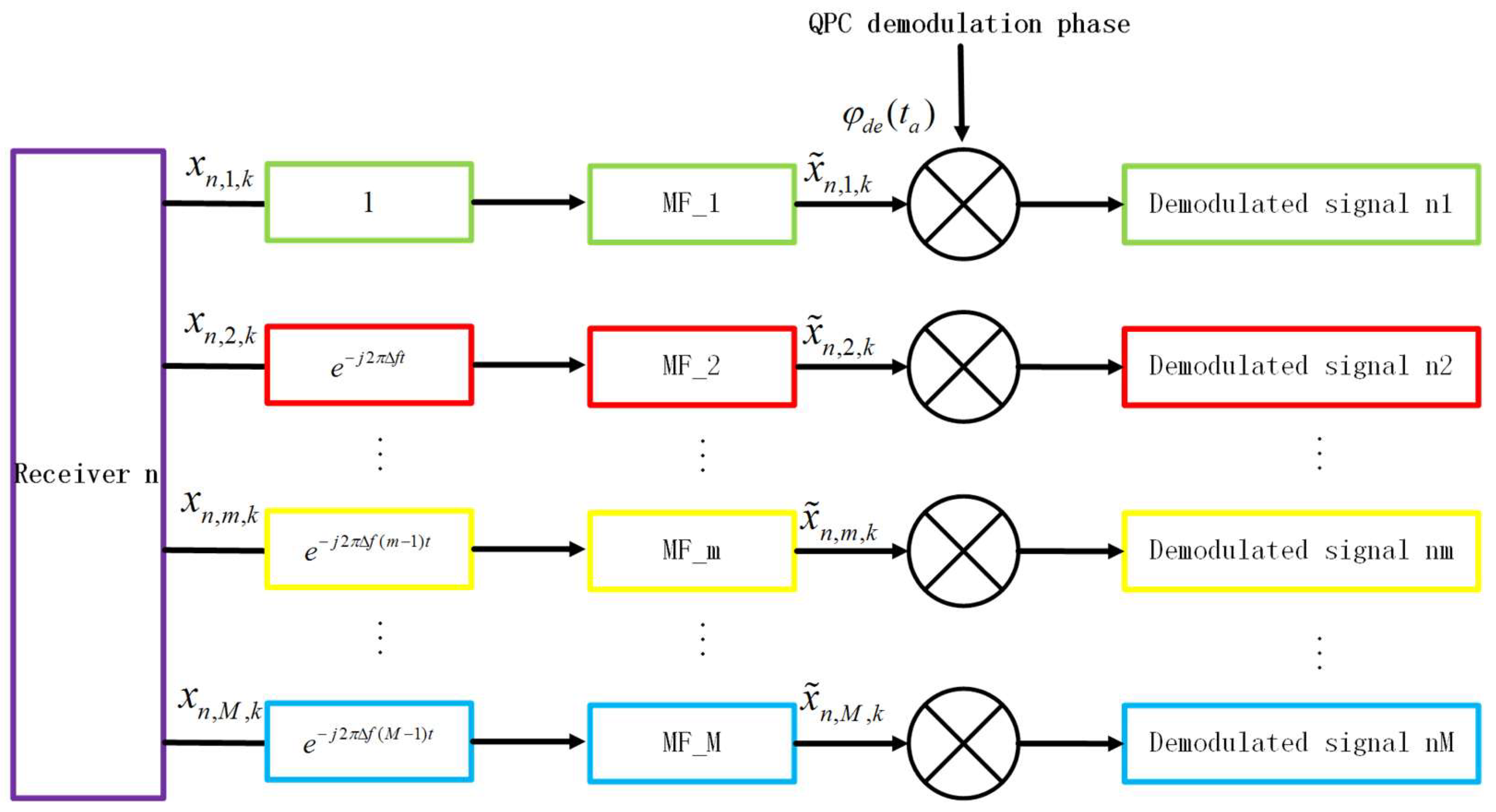
Firstly, the received signal is mixed with . Then, as is shown in Figure 1, a group of filters is utilized on each receive channel. What is more, take the -th () filter as an example, and the received signal is firstly multiplied with . Subsequently, the transmitted waveforms are separated via matched filtering, where the -th matched filter is denoted as , and the resulting signal is written as
Subsequently, the QPC demodulation is performed along the slow time, and the demodulation phase of each receive array element in the -th pulse is defined as
After QPC demodulation, the residual phase is expressed as
where the first exponential term is linearly dependent on , indicates the additional normalized Doppler shift, which is expressed as
By stacking the received signals corresponding to receive elements with pulses, the received signal is organized as an -dimensional vector, i.e.,
where with is the output vector after matched filtering, and is the targets’ normalized Doppler frequency. , and , respectively, denote the Doppler vector, the receive steering vector, and the transmit steering vector, with the forms of
3. Principle of Mainlobe Deceptive Jammer Suppression in QPC-FDA-MIMO
3.1. Generation of False Targets
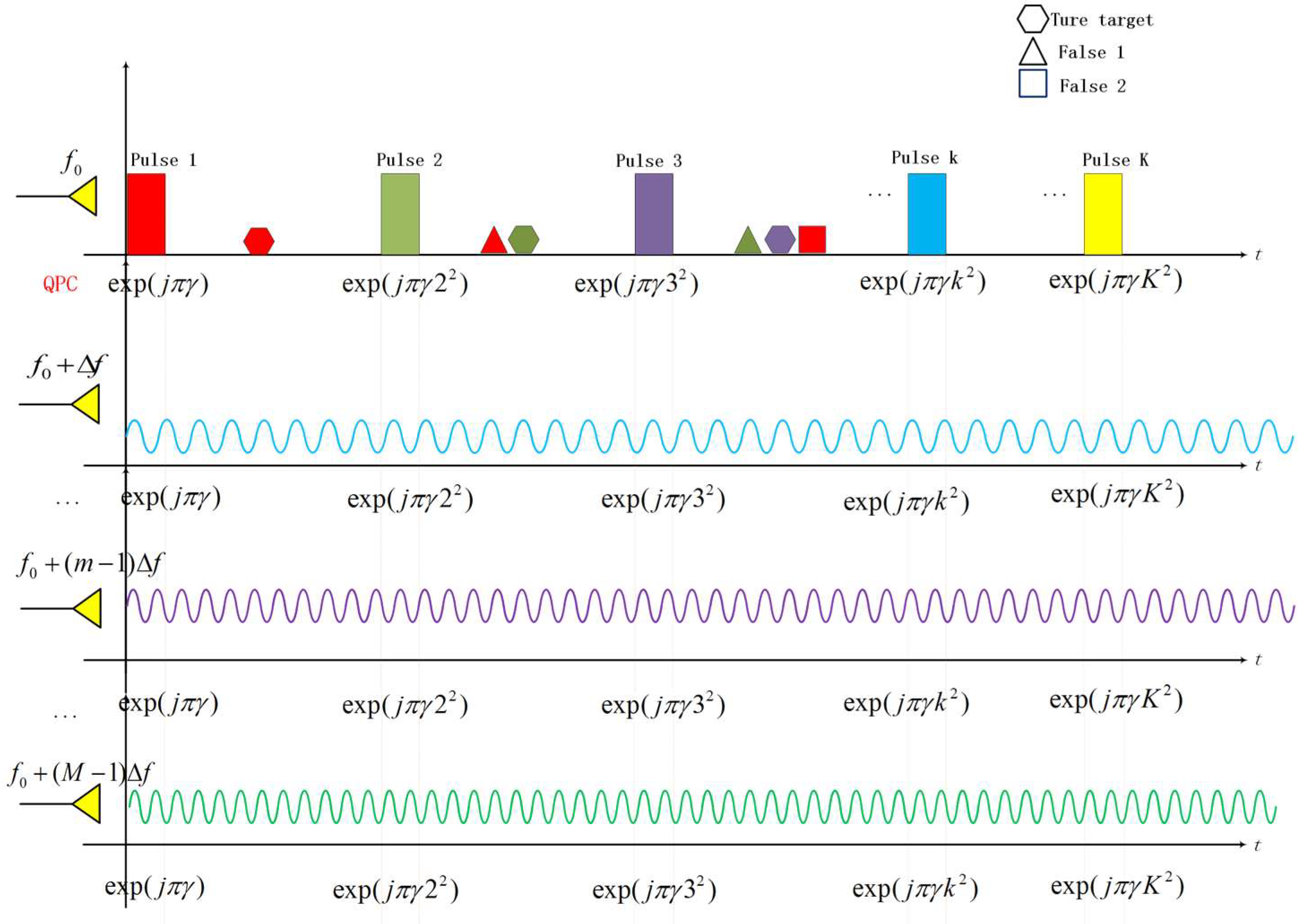
Consider a self-defense deception jammer equipped with a false target generator (FTG) situated at an identical angle to the true one, where the range deception is achieved with several pseudo-randomly distributed false targets after some appropriate modulation in DRFM. Actually, the false targets are located behind the true one either in the same received pulse or at least one transmit pulse. In this paper, the latter case is concentrated on, namely, the false targets and the true target have distinct numbers of delayed pulses.
The generation of the false targets in the QPC-FDA-MIMO radar is shown in Figure 2, where the two false targets locate at least one slow time pulse behind the true one. However, in an identical receive pulse, the false targets can be either ahead of the target, that is, the false target 1, or behind the true one, that is, the false target 2. Moreover, QPC is implemented among pulses while it is identical for all transmit elements.
Let us consider false targets and a case study of the -th () false target, whose number of delayed pulses is , and its QPC code is the same as the -th pulse as shown in Figure 2. Hence, the QPC code of the -th false target is expressed as
Then, after QPC demodulation, the residual phase is
where denotes the additional normalized Doppler frequencies of the false target, i.e.,
By collecting the received signals from all elements, the received jamming signal can be stacked into an -dimensional vector, i.e.,
where denotes the equivalent location of the -th false target after time modulation in the FTG, and denote the Doppler vector and the transmit steering vector of the -th false target, respectively with the forms of
It can be observed from (19) that after QPC demodulation, the false targets and the true target have distinct additional normalized Doppler shifts. Hence, the false targets and the true target are can be discriminated in the Doppler frequency domain.
Furthermore, the total received signal, considering false targets, the true target and the noise component, is expressed as
where denotes the white Gaussian noise with the covariance matrix, donates the -dimensional identity matrix, and donates the noise power.
3.2. Mainlobe Deceptive Jammer Suppression
Based on the transmit and receive steering vectors in the QPC-FDA-MIMO radar, the transmit spatial frequencies of the true and the -th false targets are:
where and are the actual ranges of the true and the -th false target, which are represented as
where indicates the maximum unambiguous range with the pulse repetition frequency. and indicate the principal ranges of the true target and the -th false target, respectively.
Specifically, let us construct the compensating vector as [30]
where is the range compensating frequency, and is the principal range obtained by the range bin size and the range bin number.
What is more, the receive-transmit joint compensation vector is constructed as
Then, the received data are compensated as
After the compensation range, bin-by range bin [34], the ranges of the true and the -th false target can be, respectively, written as
Accordingly, the transmit spatial frequencies of the true and the -th false target are
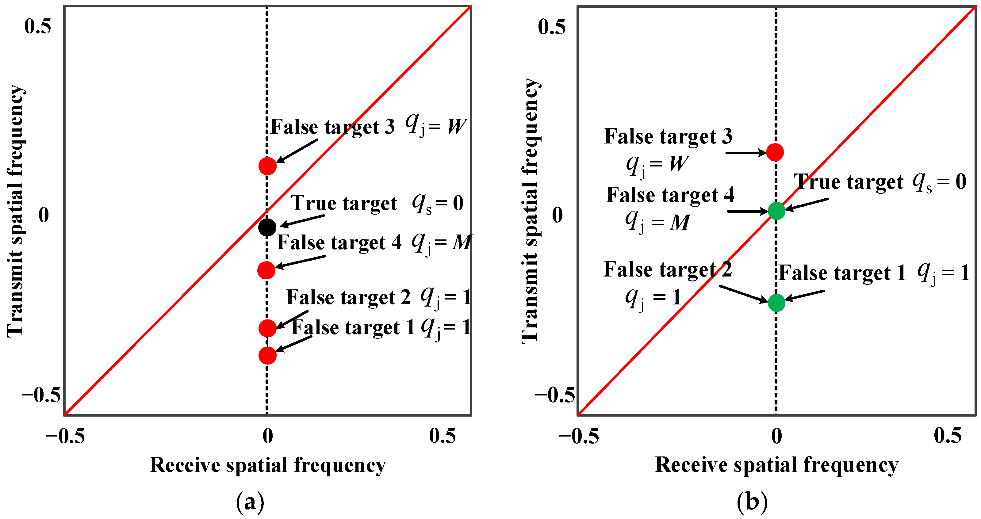
Hence, the targets relative to distinct range bins are concentrated in an identical receive pulse after range compensation [34]. In other words, the transmit spatial frequencies of the targets that are located in the same pulses (i.e., the range ambiguity region) are equal. As shown in Figure 3, after compensation, the false targets 1 and 2 are situated in the same position in the joint transmit-receive spatial frequency domain for the reason that they have identical delayed pulses. However, the false target 4 and the true target cannot be distinguished in the transmit-receive spatial domain because the number of delayed pulses is M. In order to discriminate the false target 4 and the true one, it is necessary to utilize the Doppler information.
According to (9) and (16), the difference in the Doppler frequency between the true and the -th targets is
where is the delayed pulse difference between the -th false target and the true target. It is observed from (32) that the Doppler frequency difference depends on and . By this means, the false targets and the true target can be discriminated in the Doppler frequency domain although they have an identical spatial frequency.
To proceed, a range-angle-Doppler-dependent three-dimensional (3D) beamformer is constructed via the MVDR (Minimum Variance Distortionless Response) criterion, which is written as follows
where is the virtual steering vector of the target after compensation, is the jammer-plus-noise covariance matrix after compensation, and the optimal weight vector is calculated as:
where .
Furthermore, the received data after compensation are processed through the range-angle-Doppler–dependent MVDR beamformer, and the output signal is represented as
Hence, the false targets are suppressed via range and Doppler mismatches.
3.3. Design of Frequency Increment and Coding Coefficient
In this subsection, the designs of the frequency increment and coding coefficient are investigated. Suppose for simplicity. To begin with, in the transmit frequency domain, the normalized equivalent transmit beampattern for the -th false target is
where , and when the denominator of is not zero and the numerator is zero, the nulls of the beampattern exist, i.e.,
where .
Moreover, according to (30) and (31), the difference between the transmit spatial frequencies relative to the true and the -th false target can be obtained as
where is the integer part and is the decimal part. Usually, can be ignored owing to the periodicity of the exponential term. Notice that the condition must be satisfied, otherwise, the jammer suppression is invalid because their transmit spatial frequencies are identical. Accordingly, the frequency increment is designed as
Hence, the false targets with delayed pulses are relative to the first to -th nulls of the beampattern, and by nulling at the beampattern, the false targets are suppressed.
Similarly, according to (32), the difference between the false targets and the true target in the Doppler frequency domain can be written as
where is the integer part, which is neglected due to the periodicity. is the fractional part. Similarly, must be guaranteed to distinguish the true and false targets in the Doppler frequency domain. Assume that with the maximum number of delayed pulses, thus, the false targets which are relative to to delayed pulses can be discriminated and suppressed by satisfying .
Figure 4 shows that the targets are distributed in a joint transmit-Doppler domain. It is observed that although the true target and the false target 4 cannot be discriminated in the transmit-receive frequency domain. They are distinguished in the Doppler frequency domain. In contrast, the true target and the false target 3 cannot be discriminated in the Doppler frequency domain because the difference in delayed pulses is . However, they are distinguished in the transmit-receive frequency domain. Based on the aforementioned observations, by means of nulling in the joint transmit-Doppler frequency domain, the false targets are suppressed. Then, the maximum number of the suppressible false targets in the joint transmit-receive-Doppler domain can be given as
where denotes the least common factor of and . To further increase the maximum numbers of the suppressible false targets, and are designed to be prime. Hence, the maximum number of suppressible false targets is
According to (9) and (13), when , the Doppler frequencies of the targets corresponding to distinct delayed pulses are identical, and the jammer suppression is invalid. Hence, and are no more than of the corresponding maximums, respectively. Accordingly, it is important to choose an appropriate value of to satisfy the demands of jammers suppression and speed detection simultaneously.
4. Simulations
In this section, simulation results are presented to assess the effectiveness of the jammer suppression method based on the QPC-FDA-MIMO radar. Assume that four false targets are produced in an identical FTG and the delayed pulses for the false targets 1, 2, 3, and 4 are 1, 1, 15 and 16, respectively. The parameters of the QPC-FDA-MIMO system and the targets are, respectively, listed in Table 1 and Table 2.
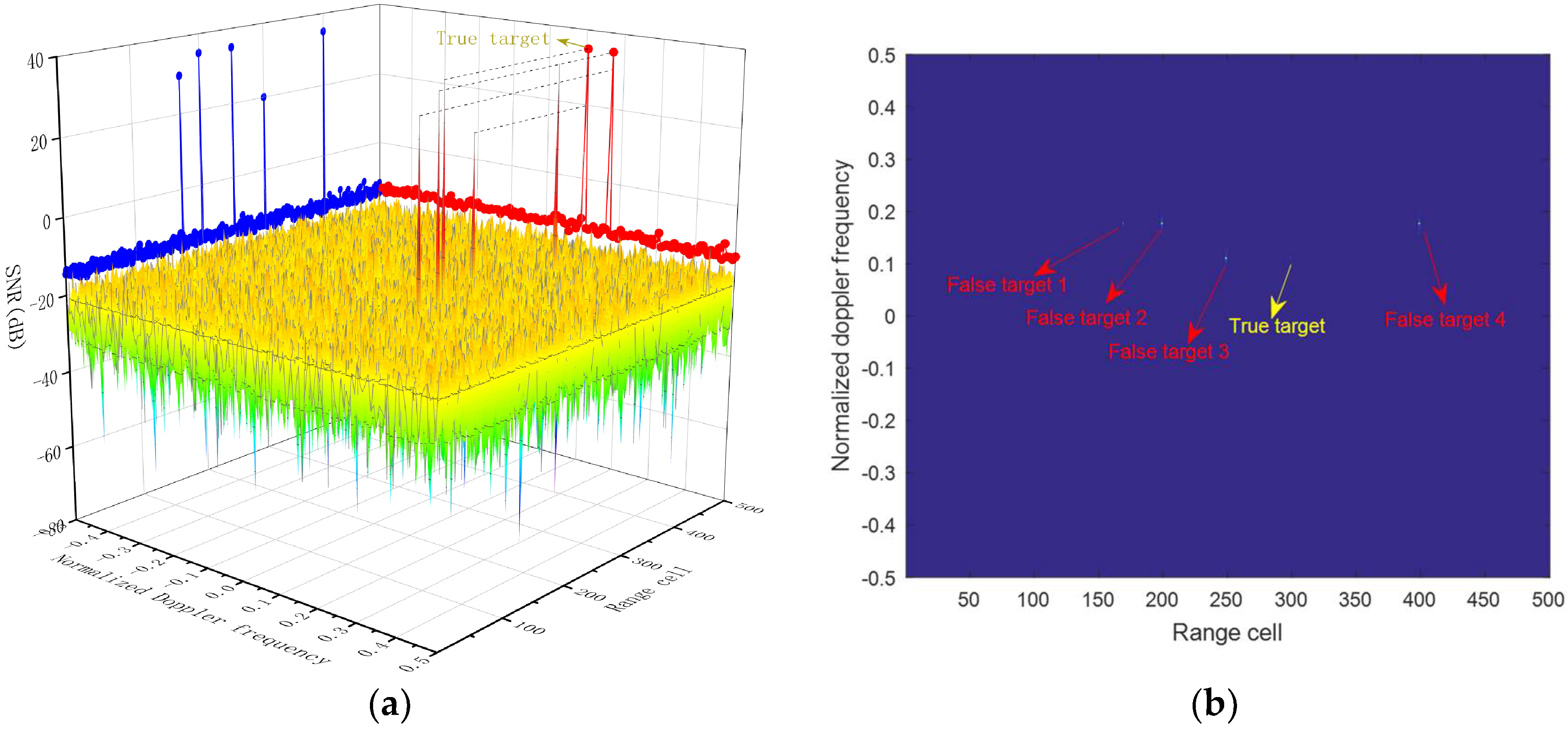
Figure 5 demonstrates the capon spectrum distributions of the targets in the joint transmit-receive spatial frequency domain. It can be seen from the result that the targets are situated at a straight line with an identical receive spatial frequency in Figure 5a. However, the transmit spatial frequencies depend on the number of delayed pulses and range bins before compensation. In contrast, after range compensation, the same delayed pulse targets are concentrated in an identical transmit spatial frequency. As is intuitively displayed in Figure 5b, false targets 1 and 2 can be discriminated from the true one, while false target 4 cannot be discriminated from the true one because it is located in the same position.
Figure 6 shows the range-Doppler spectrum distributions of the targets. It is observed in Figure 6a that, by projecting onto the Doppler domain, the targets are concentrated with two peaks. In Figure 6b, after demodulation, the true target and the false target 4, which have an identical spatial frequency, are distinguished in the joint range-Doppler frequency domain. However, although the true one and the false target 3 are distinguished in the transmit-receive spatial frequency domain as in Figure 5b, they are not distinguished in the Doppler domain because of the difference in delayed pulses is . Hence, considering the joint transmit-receive-Doppler domain, all false targets can be discriminated from the true ones.
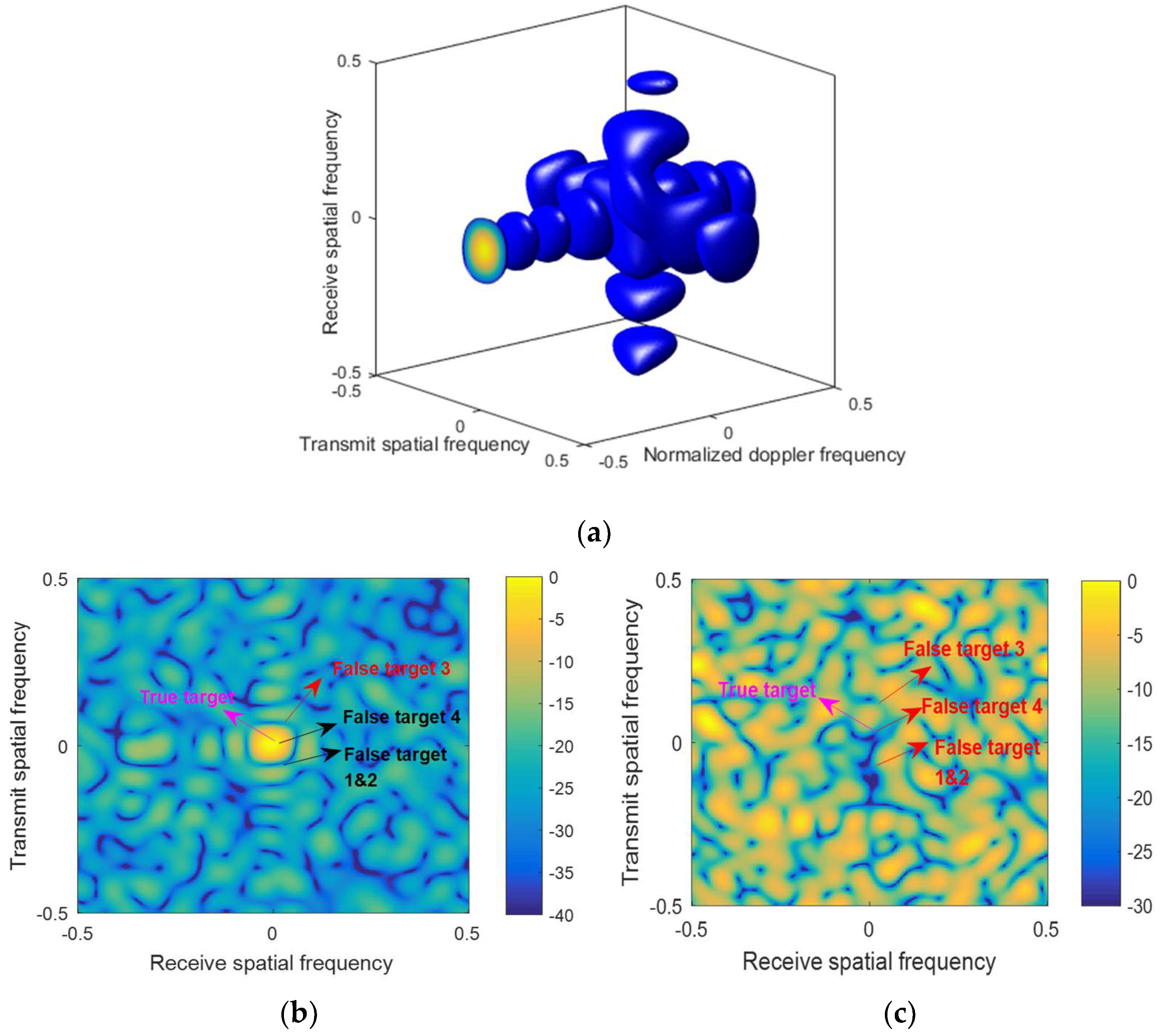
Figure 7a displays the 3D adaptive beampattern in the joint transmit-receive-Doppler domain. Moreover, the transmit-receive slice of the 3D beampattern is in the QPC-FDA-MIMO radar in Figure 7b, where . It is observed that the true one is located in the 3-D beampattern’s center, and the false target 3, which is suppressed by nulling in the spatial frequency domain, is situated at the same transmit-receive slice with the true one with an identical Doppler frequency in Figure 7b. In addition, the false target 4, which has an identical spatial frequency to the true one, is suppressed by nulling the Doppler domain. Moreover, false targets 1 and 2 can be suppressed by nulling both the Doppler frequency and the spatial frequency domains. On the contrary, the transmit-receive beampattern in the traditional FDA-MIMO radar is plotted in Figure 7c, where distortion of the beampattern occurs because the true target, which has the identical transmit spatial frequency compared with the false target 4.
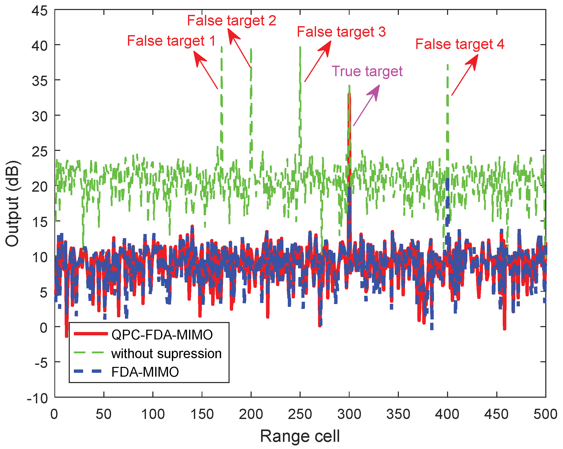
Furthermore, as is shown in Figure 8 that comparisons of the output powers among distinct radar frameworks are also provided. The true target has the maximum output power in the QPC-FDA-MIMO radar, where the false targets are suppressed in the joint transmit-receive-Doppler domain. In contrast, the false targets, whose delayed pulses are more than (such as false target 4), cannot be suppressed in the EPC-MIMO radar and FDA-MIMO radar.
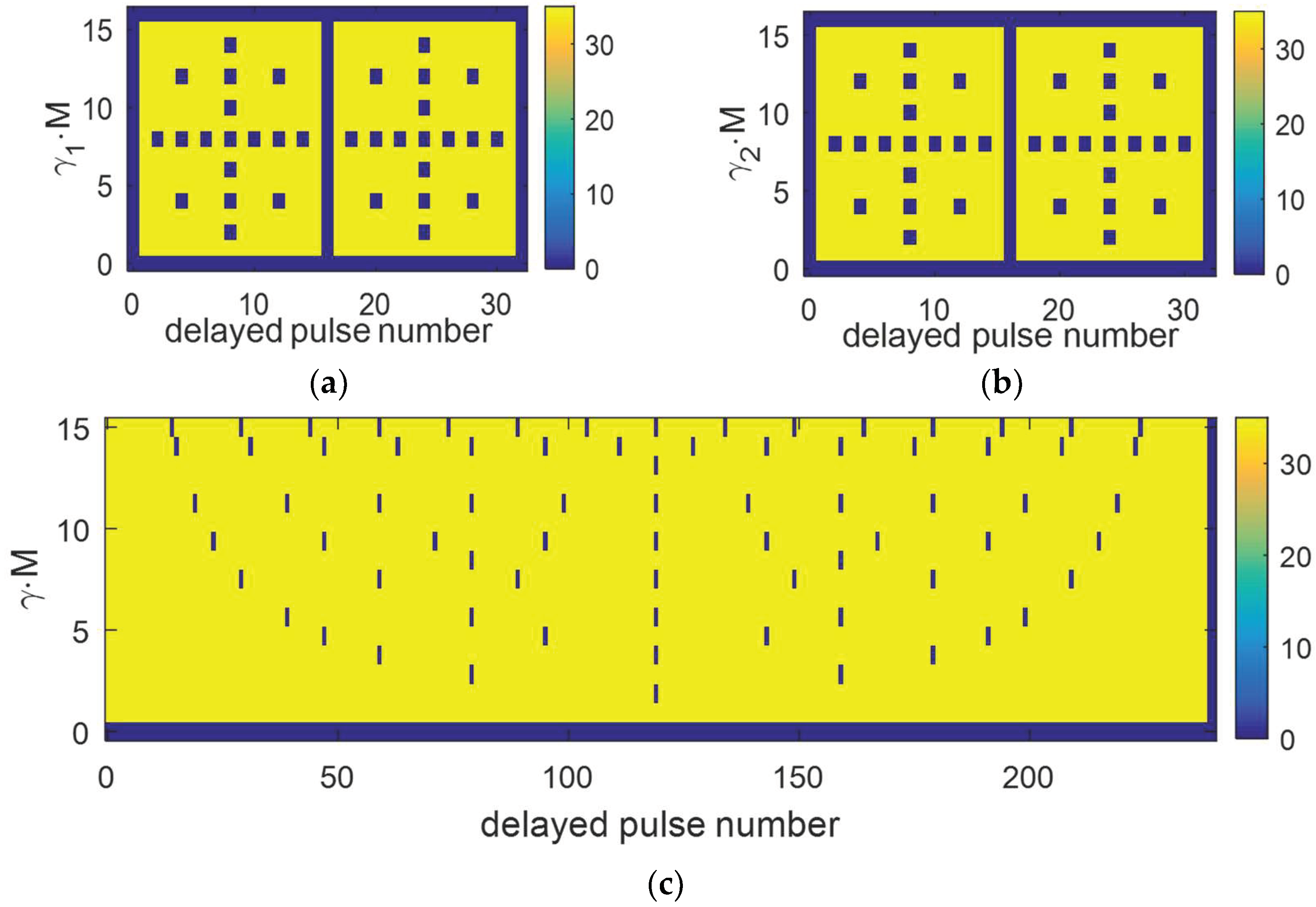
The zones of false target suppression are shown in Figure 9, where the y-axis and the x-axis denote the coding coefficient and the number of delayed pulses, respectively. Particularly, the yellow color indicates effective suppression, and the blue color indicates that the jammer’s suppression is invalid. As is intuitively shown in Figure 9a,b, by modulating with the same phase in both EPC-MIMO and FDA-MIMO, the first to the -th nulls of the beampattern correspond to the false targets; the first to the -th delayed pulses and the maximum number of suppressible jammers is . It is worth pointing out that, by setting and , the maximum number of suppressible jammers is . Hence, the proposed method has superiorities in improving the maximum number of suppressible jammers, which is in agreement with the theoretical analyses.
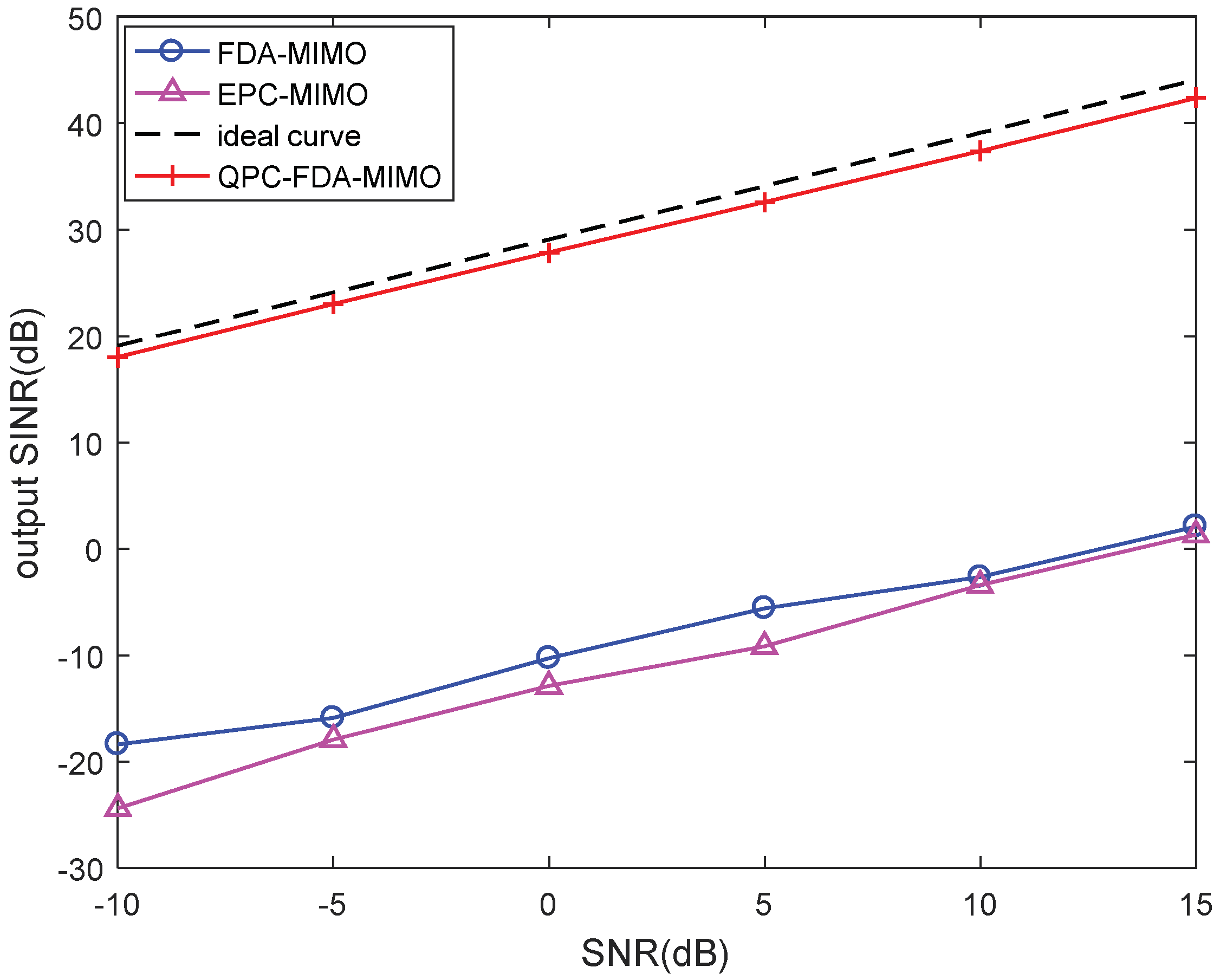
Figure 10 shows the output signal-to-jammer-plus-noise ratio (SJNR) curves versus input signal-to-noise ratio (SNR) among different radar frameworks with 150 Monte Carlo (MC) trails. What is more, the upper bound is provided as an ideal case. Remarkably, both the EPC-MIMO and FDA-MIMO radars cannot suppress the false target whose delayed pulse number is , i.e., the false target 4, leading to a low SJNR. In contrast, all false targets are effectively suppressed by means of utilizing the data-dependent transmit-receive-Doppler 3D beamforming in QPC-FDA-MIMO which improves the output SJNR performance.
5. Conclusions
In this paper, the method to suppress the main lobe deceptive jammers has been presented in the QPC-FDA-MIMO radar. In the modeling phase, QPC has been applied along the slow time dimension in the transmit array of the FDA-MIMO radar. At the receiver, the decoding and principal range compensation has been carried out to distinguish the false targets and the true target in the transmit-receive-Doppler frequency domain. Then, by performing the data-dependent transmit-receive-Doppler 3D beamforming, the false targets have been suppressed. Moreover, the coding coefficient and frequency increments have been designed to increase the maximum number of suppressible jammers. Numerical results have been presented to assess the jammer suppression performance, where comparisons among various frameworks, containing FDA-MIMO and EPC-MIMO radars, have been carried out in terms of the spectrum distribution and output SJNR. The suppression performance has been ensured and the maximum number of suppressible jammers is obviously improved in the QPC-FDA-MIMO radar.
In the future, the suppression of fast-generated false targets delayed in the same transmit pulse in comparison with the true target will be concentrated on and the scenario of multiple true targets will be considered.
Author Contributions
Conceptualization, Y.Z. and J.X.; methodology, Y.Z. and J.X.; software, L.L.; validation, Y.Z., J.X., G.L. and L.L.; formal analysis, Y.Z. and L.L.; investigation, Y.Z., L.L. and J.X.; resources, G.L.; data curation, Y.Z. and J.X.; writing—original draft preparation, Y.Z.; writing—review and editing, Y.Z., J.X. and L.L.; visualization, Y.Z. and L.L.; supervision, L.L., G.L. and J.X.; project administration, L.L., G.L. and J.X.; funding acquisition, L.L., G.L. and J.X. All authors have read and agreed to the published version of the manuscript.
Funding
This work was supported in part by the Nature Science Foundation of China (NSFC) under Grants 61931016 and 62071344, the Young Talent Starlet in Science and Technology in Shaanxi under Grant No. 2022KJXX-38, and the Key Laboratory Equipment Advanced Research Fund under Grant 6142206200210.
Conflicts of Interest
The authors declare no conflict of interest.
References
- Jin, F.; Cao, S. Automotive Radar Interference Mitigation Using Adaptive Noise Canceller. IEEE Trans. Veh. Technol. 2019, 68, 3747–3754. [Google Scholar] [CrossRef] [Green Version]
- Neemat, S.; Krasnov, O.; Yarovoy, A. An interference mitigation technique for FMCW radar using beat-frequencies interpo-lation in the STFT domain. IEEE Trans. Microw. Theory Tech. 2019, 67, 1207–1220. [Google Scholar] [CrossRef] [Green Version]
- Wen, W.; So, H. Transmit Subaperturing for Range and Angle Estimation in Frequency Diverse Array Radar. IEEE Trans. Signal Process. 2014, 62, 2000–2011. [Google Scholar]
- Cui, G.; Fu, Y.; Yu, X.; Li, J. Robust Transmitter–Receiver Design in the Presence of Signal-Dependent Clutter. IEEE Trans. Aerosp. Electron. Syst. 2018, 54, 1871–1882. [Google Scholar] [CrossRef]
- Wen, W.; Hing, S.; Alfonso, F. FDA-MIMO Signal Processing for Mainlobe Jammer Suppression. In Proceedings of the 2019 27th European Signal Processing Conference (EUSIPCO), A Coruna, Spain, 2–6 September 2019; pp. 1–5. [Google Scholar]
- Jung, H.; Van Nguyen, B.; Song, I.; Kim, K. Design of Anti-Jamming Waveforms for Time-Hopping Spread Spectrum Systems in Tone Jamming Environments. IEEE Trans. Veh. Technol. 2020, 69, 728–737. [Google Scholar] [CrossRef] [Green Version]
- Yu, X.; Cui, G.; Yang, J.; Kong, L. MIMO Radar Transmit–Receive Design for Moving Target Detection in Signal-Dependent Clutter. IEEE Trans. Veh. Technol. 2020, 69, 522–536. [Google Scholar] [CrossRef]
- Al-Salehi, A.R.; Qureshi, I.M.; Malik, A.N.; Khan, Z.; Khan, W. Throughput Enhancement for Dual-Function Radar-Embedded Communications Using Two Generalized Sidelobe Cancellers. IEEE Access 2019, 7, 91390–91398. [Google Scholar] [CrossRef]
- Li, Z.; Ye, H.; Liu, Z.; Sun, Z.; An, H.; Wu, J.; Yang, J. Bistatic SAR Clutter-Ridge Matched STAP Method for Nonstationary Clutter Suppression. IEEE Trans. Geosci. Remote Sens. 2021, 60, 1–14. [Google Scholar] [CrossRef]
- Chang, S.; Deng, Y.; Zhang, Y.; Zhao, Q.; Wang, R.; Zhang, K. An Advanced Scheme for Range Ambiguity Suppression of Spaceborne SAR Based on Blind Source Separation. IEEE Trans. Geosci. Remote Sens. 2022, 60, 1–12. [Google Scholar] [CrossRef]
- Al-Tous, H.; Barhumi, I.; Al-Dhahir, N. Narrow-Band Interference Mitigation Using Compressive Sensing for AF-OFDM Systems. IEEE Trans. Veh. Technol. 2017, 66, 6146–6159. [Google Scholar] [CrossRef]
- Yang, J.; Thompson, J.; Huang, X.; Jin, T.; Zhou, Z. Random-Frequency SAR Imaging Based on Compressed Sensing. IEEE Trans. Geosci. Remote Sens. 2013, 51, 983–994. [Google Scholar] [CrossRef]
- Lin, Z.; Chen, Y.; Liu, X.; Jiang, R.; Shen, B. Adaptive Beamforming Design of Planar Arrays Based on Bayesian Compressive Sensing. IEEE Sensors J. 2021, 21, 5185–5194. [Google Scholar] [CrossRef]
- Yang, J.; Jin, T.; Huang, X.; Thompson, J.; Zhou, Z. Sparse MIMO Array Forward-Looking GPR Imaging Based on Compressed Sensing in Clutter Environment. IEEE Trans. Geosci. Remote Sens. 2014, 52, 4480–4494. [Google Scholar] [CrossRef]
- Zhang, X.; Ma, H.; Wang, J.; Zhou, S.; Liu, H. Game Theory Design for Deceptive Jamming Suppression in Polarization MIMO Radar. IEEE Access 2019, 7, 114191–114202. [Google Scholar] [CrossRef]
- Jabran, A.; Karl, E. Frequency Agility Radar with Overlapping Pulses and Sparse Reconstruction. In Proceedings of the 2018 IEEE Radar Conference (RadarConf18), Oklahoma City, OK, USA, 23–27 April 2018; pp. 0061–0066. [Google Scholar]
- Tang, Z.; Deng, Y.; Zheng, H.; Wang, R. High-Fidelity SAR Intermittent Sampling Deceptive Jamming Suppression Using Azimuth Phase Coding. IEEE Geosci. Remote Sens. Lett. 2021, 18, 489–493. [Google Scholar] [CrossRef]
- Amin, M.; Zhao, L.; Lindsey, A. Subspace array processing for the suppression of FM jamming in GPS receivers. IEEE Trans. Aerosp. Electron. Syst. 2004, 40, 80–92. [Google Scholar] [CrossRef]
- Yang, X.; Zhang, Z.; Zeng, T.; Long, T.; Sarkar, T.K. Mainlobe Interference Suppression Based on Eigen-Projection Processing and Covariance Matrix Reconstruction. IEEE Antennas Wirel. Propag. Lett. 2014, 13, 1369–1372. [Google Scholar] [CrossRef]
- Chen, H.-F.; Cao, X.-R.; Fang, H.-T.; Zhu, J. Nonlinear adaptive blind whitening for MIMO channels. IEEE Trans. Signal Process. 2005, 53, 2635–2647. [Google Scholar] [CrossRef]
- Ting, S.; Yong, G. TDOA estimation of dual-satellites interference localization based on blind separation. J. Syst. Eng. Electron. 2019, 30, 696–702. [Google Scholar]
- Ge, M.; Cui, G.; Kong, L. Main lobe jamming suppression for distributed radar via joint blind source separation. IET Radar Sonar Navig. 2019, 13, 1189–1199. [Google Scholar] [CrossRef]
- Ma, J.; Shi, L.; Xiao, S.; Wang, X. Mitigation of cross-eye jamming using a dual-polarization array. J. Syst. Eng. Electron. 2018, 29, 491–498. [Google Scholar]
- Park, K.; Seo, J. Single-antenna-based GPS anti-jamming method exploiting polarization diversity. IEEE Trans. Aer-Ospace Electron. Syst. 2021, 57, 919–934. [Google Scholar] [CrossRef]
- Dai, H.; Wang, X.; Li, Y.; Liu, Y.; Xiao, S. Main-Lobe Jamming Suppression Method of using Spatial Polarization Characteristics of Antennas. IEEE Trans. Aerosp. Electron. Syst. 2012, 48, 2167–2179. [Google Scholar] [CrossRef]
- Xu, J.; Liao, G.; Zhu, S.; Huang, L.; So, H.C. Joint Range and Angle Estimation Using MIMO Radar With Frequency Diverse Array. IEEE Trans. Signal Process. 2015, 63, 3396–3410. [Google Scholar] [CrossRef]
- Sammartino, P.; Baker, C.; Griffiths, H. Frequency diverse MIMO techniques for radar. IEEE Trans. Aerosp. Electron. Syst. 2013, 49, 201–222. [Google Scholar] [CrossRef]
- Lan, L.; Marino, A.; Aubry, A.; De Maio, A.; Liao, G.; Xu, J.; Zhang, Y. GLRT-Based Adaptive Target Detection in FDA-MIMO Radar. IEEE Trans. Aerosp. Electron. Syst. 2021, 57, 597–613. [Google Scholar] [CrossRef]
- Xu, J.; Zhu, S.; Liao, G. Range Ambiguous Clutter Suppression for Airborne FDA-STAP Radar. IEEE J. Sel. Top. Signal Process. 2015, 9, 1620–1631. [Google Scholar] [CrossRef]
- Lan, L.; Xu, J.; Liao, G.; Zhang, Y.; Fioranelli, F.; So, H.C. Suppression of Mainbeam Deceptive Jammer With FDA-MIMO Radar. IEEE Trans. Veh. Technol. 2020, 69, 11584–11598. [Google Scholar] [CrossRef]
- Xu, J.; Liao, G.; Zhang, Y.; Ji, H.; Huang, L. An Adaptive Range-Angle-Doppler Processing Approach for FDA-MIMO Radar Using Three-Dimensional Localization. IEEE J. Sel. Top. Signal Process. 2016, 11, 309–320. [Google Scholar] [CrossRef]
- Lan, L.; Liao, G.; Xu, J.; Zhang, Y.; Fioranelli, F. Suppression approach to main-beam deceptive jamming in FDA-MIMO radar using nonhomo-geneous sample detection. IEEE Access 2018, 6, 34582–34597. [Google Scholar] [CrossRef]
- Wang, W.-Q.; So, H.C.; Farina, A. An Overview on Time/Frequency Modulated Array Processing. IEEE J. Sel. Top. Signal Process. 2017, 11, 228–246. [Google Scholar] [CrossRef]
- Xu, J.; Liao, G.; Zhu, S.; So, H.C. Deceptive jamming suppression with frequency diverse MIMO radar. Signal Process. 2015, 113, 9–17. [Google Scholar] [CrossRef]
- Lan, L.; Liao, G.; Xu, J.; Zhang, Y.; Liao, B. Transceive Beamforming With Accurate Nulling in FDA-MIMO Radar for Imaging. IEEE Trans. Geosci. Remote Sens. 2020, 58, 4145–4159. [Google Scholar] [CrossRef]
- Xu, J.; Zhang, Y.; Liao, G.; So, H.C. Resolving Range Ambiguity via Multiple-Input Multiple-Output Radar With Element-Pulse Coding. IEEE Trans. Signal Process. 2020, 68, 2770–2783. [Google Scholar] [CrossRef]
- Lan, L.; Liao, G.; Xu, J.; Zhang, Y.; Zhu, S. Mainlobe deceptive jammer suppression using element-pulse coding with MIMO radar. Signal Process. 2021, 182, 107955. [Google Scholar] [CrossRef]
- Zhang, X.; Cao, D.; Xu, L. Joint polarisation and frequency diversity for deceptive jamming suppression in MIMO radar. IET Radar Sonar Navig. 2019, 13, 263–271. [Google Scholar] [CrossRef]
- Liu, Q.; Xu, J.; Ding, Z.; So, H.C. Target Localization With Jammer Removal Using Frequency Diverse Array. IEEE Trans. Veh. Technol. 2020, 69, 11685–11696. [Google Scholar] [CrossRef]
- Ge, J.; Xie, J.; Wang, B. A cognitive active anti-jamming method based on frequency diverse array radar phase center. Digit. Signal Process. 2021, 109, 102915. [Google Scholar] [CrossRef]
Figure 1.
Procedures of receive processing.

Figure 2.
Illumination of true and false targets with QPC-FDA-MIMO.

Figure 3.
Distribution of the targets in the joint transmit-receive domain. (a) Before compensation. (b) After compensation.
Figure 3.
Distribution of the targets in the joint transmit-receive domain. (a) Before compensation. (b) After compensation.

Figure 4.
Distribution of the targets in joint transmit-Doppler domain.

Figure 5.
Capon spectrum distributions in the transmit-receive frequency domain. (a) Before range compensation. (b) After range compensation.
Figure 5.
Capon spectrum distributions in the transmit-receive frequency domain. (a) Before range compensation. (b) After range compensation.

Figure 6.
Range-Doppler spectrum distribution. (a) 3-D plot. (b) 2-D plot.

Figure 7.
Beampatterns. (a) Transmit-receive-Doppler 3D beampattern of the QPC-FDA-MIMO radar. (b) Transmit-receive slice of the 3D beampattern of the QPC-FDA-MIMO radar. (c) Transmit-receive beampattern of the FDA-MIMO radar.
Figure 7.
Beampatterns. (a) Transmit-receive-Doppler 3D beampattern of the QPC-FDA-MIMO radar. (b) Transmit-receive slice of the 3D beampattern of the QPC-FDA-MIMO radar. (c) Transmit-receive beampattern of the FDA-MIMO radar.

Figure 8.
Comparison of output results.

Figure 9.
Suppression zones of false targets. (a) EPC-MIMO. (b) FDA-MIMO. (c) QPC-FDA-MIMO.

Figure 10.
Output SJNR performance with respect to input SNR.


Table 1.
Parameters of QPC-FDA-MIMO system.
| Parameter | Value | Parameter | Value |
|---|---|---|---|
| The carrier frequency | 16 GHz | Pulse repetition frequency | 10 kHz |
| Transmit elements number | 16 | Receive elements number | 16 |
| Transmit elements space | 0.0093 m | Receive elements space | 0.0093 m |
| Coding coefficient | 1/15 | Frequency increment | 0.625 kHz |
Table 2.
Parameters of targets.
| True Target | False Target 1 | False Target 2 | False Target 3 | False Target 4 | |
|---|---|---|---|---|---|
| Angle (°) | 0 | 0 | 0 | 0 | 0 |
| Range(km) | 9 | 20.1 | 21 | 232.5 | 252 |
| Range bin | 300 | 170 | 200 | 250 | 400 |
| Time delay (ms) | 0.06 | 0.134 | 0.14 | 1.55 | 1.68 |
| Velocity (m/s) | 10 | 10 | 10 | 10 | 10 |
| SNR/JNR (dB) | 10 | 20 | 25 | 25 | 25 |
| Delayed pulse | 0 | 1 | 1 | 15 | 16 |
Publisher’s Note: MDPI stays neutral with regard to jurisdictional claims in published maps and institutional affiliations. |
© 2022 by the authors. Licensee MDPI, Basel, Switzerland. This article is an open access article distributed under the terms and conditions of the Creative Commons Attribution (CC BY) license (https://creativecommons.org/licenses/by/4.0/).
Share and Cite
MDPI and ACS Style
Zhang, Y.; Liao, G.; Xu, J.; Lan, L. Mainlobe Deceptive Jammer Suppression Based on Quadratic Phase Coding in FDA-MIMO Radar. Remote Sens. 2022, 14, 5831. https://doi.org/10.3390/rs14225831
AMA Style
Zhang Y, Liao G, Xu J, Lan L. Mainlobe Deceptive Jammer Suppression Based on Quadratic Phase Coding in FDA-MIMO Radar. Remote Sensing. 2022; 14(22):5831. https://doi.org/10.3390/rs14225831
Chicago/Turabian StyleZhang, Yiqun, Guisheng Liao, Jingwei Xu, and Lan Lan. 2022. "Mainlobe Deceptive Jammer Suppression Based on Quadratic Phase Coding in FDA-MIMO Radar" Remote Sensing 14, no. 22: 5831. https://doi.org/10.3390/rs14225831
Note that from the first issue of 2016, this journal uses article numbers instead of page numbers. See further details here.