
Dynamics of Single Droplet Splashing on Liquid Film by Coupling FVM with VOF


1
Key Laboratory of Fluid Transmission Technology of Zhejiang Province, Zhejiang Sci-Tech University, Hangzhou 310018, China
2
College of Energy Engineering, Zhejiang University, Hangzhou 310058, China
3
Hangzhou Yunze Environmental Science& Technology Company, Hangzhou 310051, China
*
Author to whom correspondence should be addressed.
Processes 2021, 9(5), 841; https://doi.org/10.3390/pr9050841
Submission received: 23 April 2021
/
Revised: 7 May 2021
/
Accepted: 7 May 2021
/
Published: 11 May 2021
Abstract
:A three-dimensional numerical study of a single droplet splashing vertically on a liquid film is presented. The numerical method is based on the finite volume method (FVM) of Navier–Stokes equations coupled with the volume of fluid (VOF) method, and the adaptive local mesh refinement technology is adopted. It enables the liquid–gas interface to be tracked more accurately, and to be less computationally expensive. The relationship between the diameter of the free rim, the height of the crown with different numbers of collision Weber, and the thickness of the liquid film is explored. The results indicate that the crown height increases as the Weber number increases, and the diameter of the crown rim is inversely proportional to the collision Weber number. It can also be concluded that the dimensionless height of the crown decreases with the increase in the thickness of the dimensionless liquid film, which has little effect on the diameter of the crown rim during its growth.
1. Introduction
Droplet impacts are widespread in our lives and in industrial technology area, whose collision behavior occurrs everywhere. For example, the impact of raindrops on porous soil is considered to be one of the main causes of floating dust in the air. During the pesticide spraying process, more than 50% of the pesticide droplets are wasted due to their rebounding after colliding with crop leaves [1]. The collision behavior of ink droplets in inkjet printing plays a key role in the quality of printing. In the past two decades, researchers have carried out a lot of research on the droplet impact on the impermeable wall and have made some progresses. However, in real cases, a thin liquid film will form on the impermeable wall after being continuously impacted by the droplets, l. Therefore, it is more practical to study the phenomenon of the droplets hitting the liquid film.
The main parameters considered in the process of impact on the liquid film are the film thickness h, the diameter D0 and impact velocity U0 of the droplet, the density ρ, the viscosity μ of the liquid, the surface tension σ, and the time t, while the corresponding sets of dimensionless parameters are the Weber number (We), the Ohnesorge number (Oh), the Reynolds number (Re), the dimensionless film thickness (H*), and the dimensionless time (T) [2], which are defined as:
The study of droplets on liquid film mainly focuses on the formation mechanisms and dynamic characteristics of the neck jet, the crown spray, splash critical parameters, and secondary droplet prediction, etc. [3]. When a droplet vertically impinges on the liquid film with velocity, the velocity of the droplet changes dramatically within a very short time after the collision. This inevitably causes the liquid film to form a crown. During the development of the crown, two opposing driving forces dominate: inertial force, which tends to stretch the crown, and surface tension, which tends to shrink it. When the relative effects of inertial force and surface tension are different, the impinging behavior of the droplets will be different. In the early stages, the studies about the impact of droplets on liquid film are mainly based on experimental research and theoretical analysis. Cossali et al. [4] studied the impact morphology of millimeter droplets and the formation of secondary droplets by experimental photographic methods. The characteristic times of the crown formation and the critical Weber number of droplet splashing/deposition limit under various conditions were determined. Gueyern and Zaleski [5] compared theoretical predictions of crown formation and evolution by high-resolution axisymmetric simulations of the full Navier–Stokes equation, with the results suggesting a possible mechanism for finger formation in the early stages of impact when the effect of surface tension can be ignored. Yarin and Weiss [6] studied the effect of low-speed impact on capillary wave propagation through experimental and theoretical analysis. They also noted that the crown was unstable due to the formation of cusps on the free edges of it, which could lead to splashing. Rioboo et al. [7] found that there were three main phenomena after the impact: deposition, formation of crown spray and splashing. According to the experimental results, the thresholds of those three situations were determined. Vander Wal [8] defined two different splash modes through experiments: instant splash (secondary droplets would be produced when the crown splash is developing) and delayed splash (the second droplet separates from the top edge of the crown when the crown splash is fully developed), which is mainly related to the fluid’s viscosity. The experiment of Hao [9] indicates that slight roughness significantly enhances the prompt splashing of droplets. Okawa et al. [10] found that the critical Weber number for the early splash to occur is dependent on the liquid properties (more specifically, the Ohnesorge number) but not on the liquid film thickness. However, the critical Weber number of the delayed splash was influenced by both the liquid properties and the liquid film thickness. Naveen et al. [11] experimentally investigated the influence of the liquid droplet temperature on thermo–hydrodynamics of a single droplet impinging on surfaces with different hydrophobicity profiles.
With the development of computational fluid dynamics technology, there are a lot of valuable research achievements in the numerical simulation of droplet impact on liquid film. Harlow and Shannon [12] first attempted to conduct a numerical simulation of droplet impact. Although these simulations can be considered to be milestones, they are two-dimensional and therefore not suitable for further understanding of the mechanisms of marginal instability. Based on the boundary integral method of scalar velocity potential integral equation, Weiss and Yarin [13] proposed that when the impact Weber number is large enough, the jet would clamp the circular liquid at its tip or reconnect with the pre-existing liquid film, thereby entraining torus-shaped bubbles. Moreover, the liquid torus would decay due to Rayleigh’s capillary instability, leading to the breaking of the cylindrical symmetry. Shi et al. [14], Zhao et al. [15], and Raman et al. [16,17] observed that the velocity of the droplet has a great influence on the droplet’s impacting dynamics through the hybrid lattice Boltzmann method. Guo and Dai [18] numerically simulated the vertical impact of two droplets on a solid surface and studied the influence of droplet velocity, film thickness, as well as the distance between two droplets in regard to the splash and diffusion processes. Rieber and Frohn [19] analyzed the expansion kinetics of splash-sheet and compared it with Yarin’s theoretical results [6]. The results showed that the Rayleigh instability is the cause of the cusp formation. Guo et al. [20] combined the level set method with the VOF (CLSVOF) to analyze the effect of collision velocity and film thickness on the diameter of the crown in two dimensions. Nikolopoulos et al. [21] used VOF and the adaptive local mesh refinement technique to obtain the correlation formulas for the diameter and number of secondary droplets. Gupta and Kumar [22] presented the simulations of the water drop impact on a deep liquid pool with a moving free surface and found the volume of the secondary droplet pinched-off from the tip of the jet increased with the inclination degree of the jet. Yuan et al. [23] used the axisymmetric-boundary lattice Boltzmann method (LBM) to study the influence of different parameters such as Reynolds number, Weber number, and liquid film thickness on the behavior of the crown.
In this paper, a three-dimensional numerical simulation of a single droplet impinging on a liquid film was carried out using FLUENT (17.0, ANSYS company, Canonsburg, PA, USA, 2016)simulation software. The relationships between the diameter of the free rim and the crown height under different collision velocities and liquid film thicknesses were investigated.
2. Numerical Method
2.1. Mathematical Formulation
The process of droplets hitting the liquid film is a complex two-phase flow process in which the interface between the liquid and the gas can be significantly deformed, which brings great difficulties to its simulation. The flow caused by the droplets impinging on the wall is considered incompressible and laminar. The two-phase flow is mathematically described by the Navier–Stokes equations and the continuity equations, and the surface tension is also under consideration. The first phase is the surrounding gas phase, while the second phase is the liquid phase. To identify two phases separately, Hirt and Nichol introduced a volume fraction (expressed as “α”) based on the VOF method [24], where α is defined as:
The relationship between the values of density and viscosity with the two-phase volume fraction α is defined as follows:
where the α-function is defined as:
The momentum conservation equations of both phases could be written in the form:
where is the stress tensor, denotes the velocity, and represents the body force due to surface tension. The value of is equal to , where σ is the surface tension (for immiscible fluids the value is always positive) and κ is the local curvature of the interface region.
2.2. The Numerical Solution Procedure
In order to avoid the problem of pressure velocity coupling, the SIMPLE algorithm proposed by Patankar and Spalding [25] is used to solve the governing equations of mass and momentum balances. The high-resolution convection diffusion differential scheme proposed by Jasak [26] is used to discretize the convection term of the velocity component. The second order Crank–Nicolson difference scheme is used to discretize the time derivative. For the reason that low diffusive behavior and other discretization schemes are not able to capture interface between two fluids, the high-resolution CICSAM difference scheme including implementation of α (VOF-variable) in the transport equation is adopted [27]. Moreover, the non-diffusion of the CICSAM scheme was proved by Theodorakakos and Bergeles [28]. The continuity and momentum equations are solved both for the gas and liquid phases at each timestep (at a very small timestep, 10−6 s) and the Courant number is between 0.2 and 0.3.
Considering the high flow gradient near the free surface of the droplets, adaptive local mesh refinement technology developed by Theodorakakos and Bergeles [28] was applied in this paper, which successfully keeps the arithmetic error of mass conservation in the calculation process 0.02% lower than other methods. In order to keep the interface within the optimal mesh resolution, a new locally refined grid is created every 20 timesteps, and different levels of adaptive grids are used for grid independence verification, which will be presented afterwards. Obviously, compared with uniform mesh with equivalent fine resolution, current dynamic adaptive mesh owns a higher computational efficiency.
2.3. Numerical Details
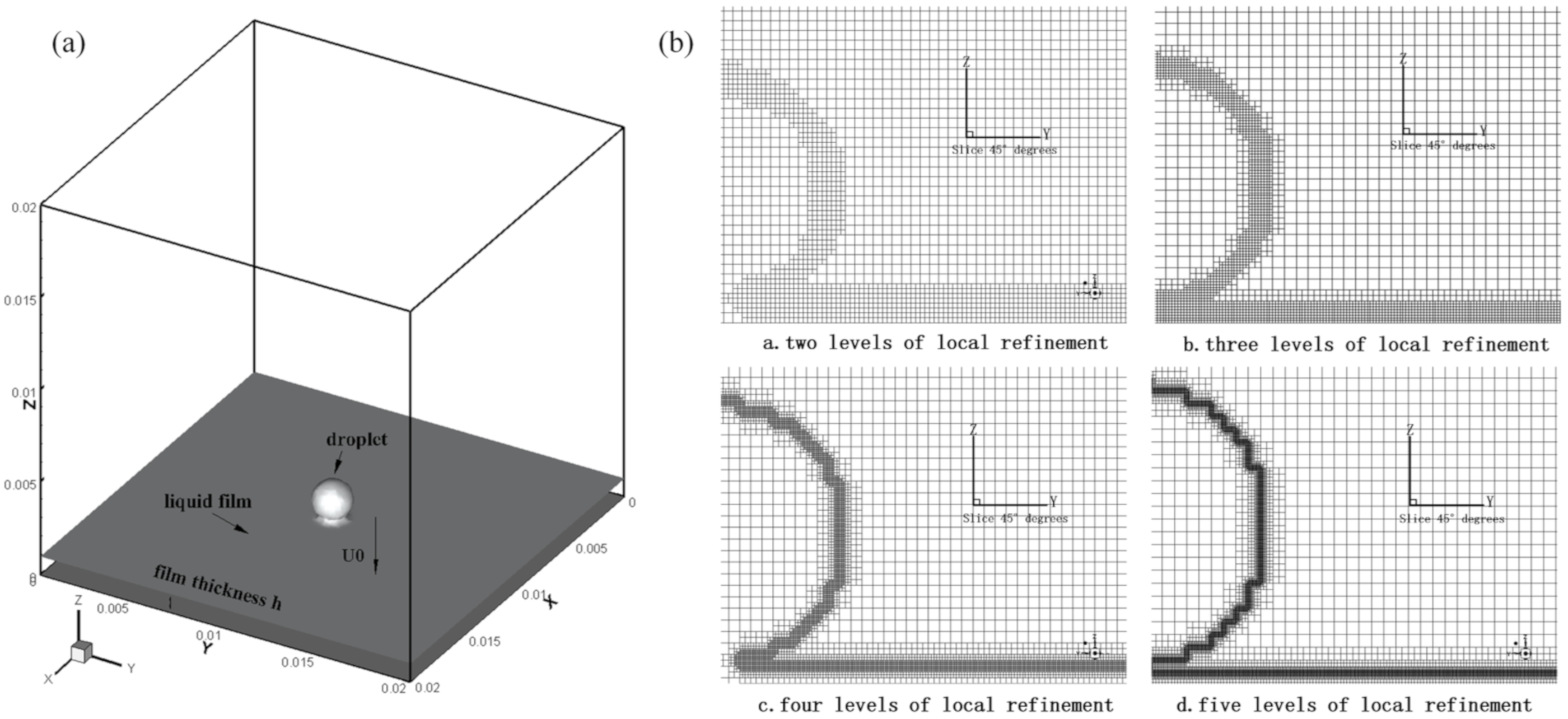
In this paper, the computational domain is divided by the hexahedral structured grid. The 3D computational domain is shown in Figure 1a. The droplet vertically impacts the liquid film with velocity Uo, and the surrounding wall is set as the pressure boundary condition.
The initial time is set when droplets first touch the film. The plane Z = 0 is the bottom surface of the liquid film. So as to examine the feasibility of the numerical method and the effect of local adaptive grids with different series, the 2- to 5-level adaptive grid method is applied to carry out numerical simulations. The minimum grid size will decrease exponentially with the increase in the adaptive grid series. So as to better show the grid details, the semi-local grid details diagram of the cross sections at X = 0.01 m are captured. The detailed parameters and grid schematic of the different levels of the adaptive grid are shown in Table 1 and Figure 1b. The basic grid employed consists of one million cells, with its minimum mesh size around the interface being equal to D0/23. After comparison and verification, we adopt four levels of the local adaptive grid resulting in the maximum number of computation cells being 8.75 million. If uniform fine mesh is used, the number of cells required to appear as the same resolution at the liquid–gas interface would be 512 million. As a result, the minimum refinement cell size equals D0/180. It would become more time-consuming. Obviously, the dynamic adaptive grid can improve the computational efficiency significantly.
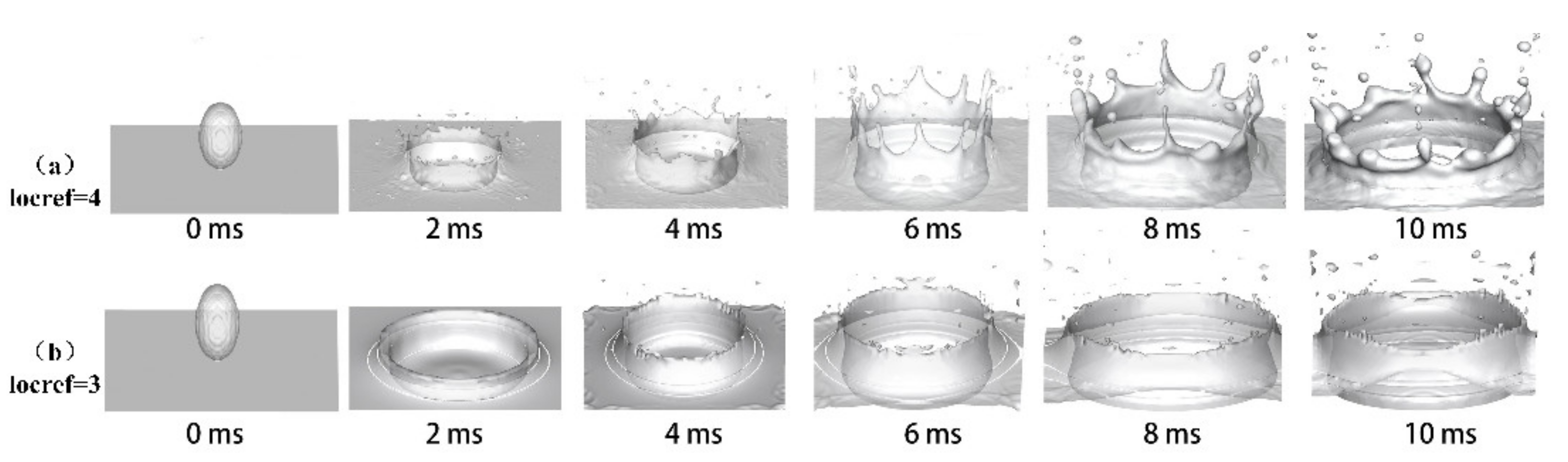
The results of numerical simulations of the droplet splashing process, with conditions V = 3.3 m/s, H* = 0.45, and d = 4.5 mm, by using two different levels of local refinement, are shown in Figure 2.
Figure 2a shows the simulation under four levels of local refinement (locref = 4). It can be clearly seen that the droplets fall off from the crown rim and form secondary droplets when the collision time t equals to 2 ms. Figure 2b shows the simulation under three levels of local refinement (locref = 3), where the crown rim is very smooth and without secondary droplets falling from the edge. Therefore, when the adaptive mesh order is less than 3, the mesh accuracy of the liquid–gas free interface is not enough to simulate the process of droplet splashing.
Comparing Figure 2a with the experimental investigations in reference [29] under the same condition (V = 3.3 m/s, H* = 0.45 and d = 4.5 mm), the simulated droplet splashing corresponds with the experimental results. We adopt the four-level local adaptive grid method in the subsequent cases through comparison results.
Table 2 lists the range of parameters required for the calculations. The diameter of droplets in all cases is 2 mm, and both the droplets and liquid film are modeled with room-temperature water.
3. Simulation Results and Discussion
3.1. Dynamics Analysis of a Droplet’s Initial Impact on Liquid Film
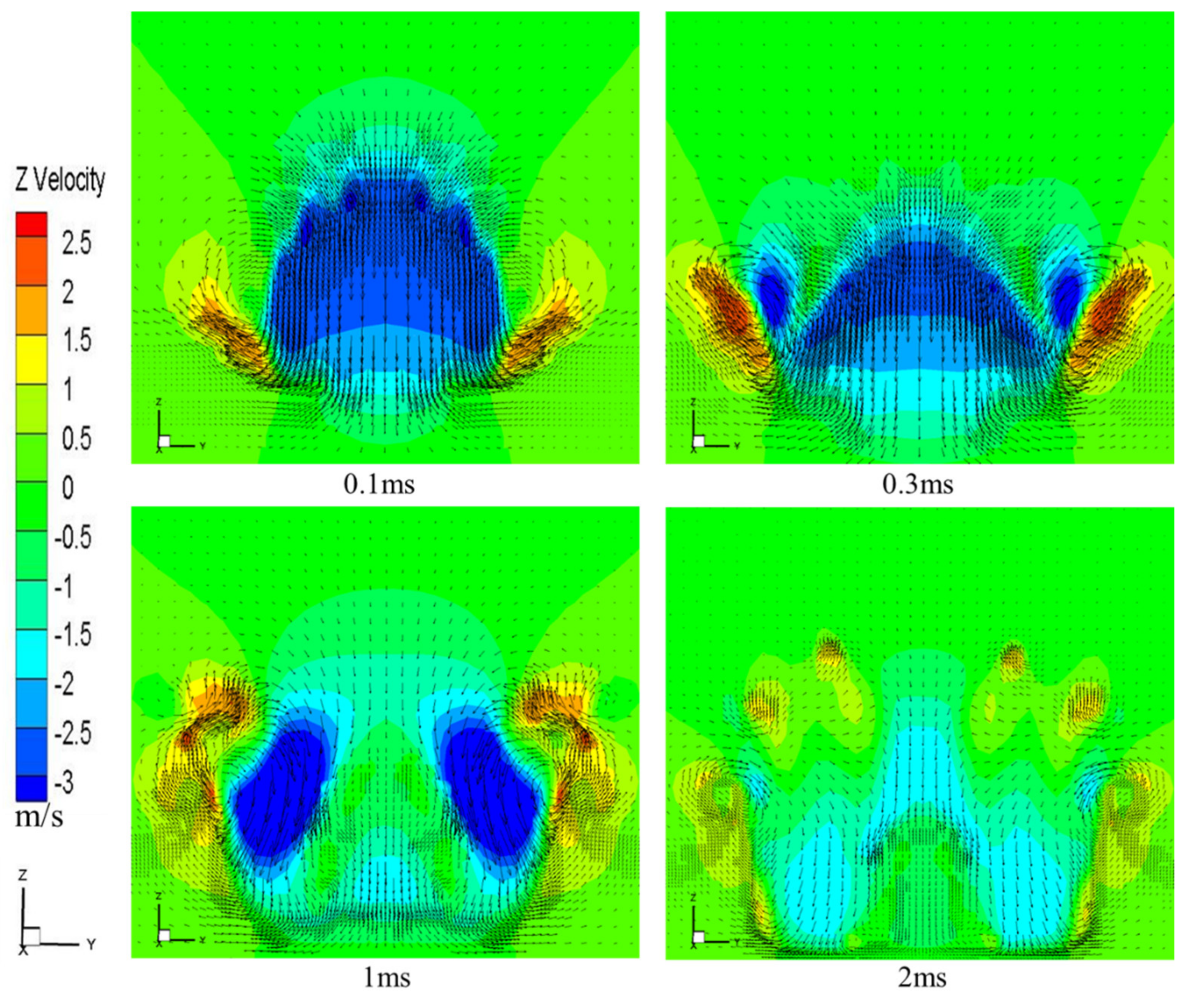
In order to analyze the dynamics of the droplet impacting the liquid film at the initial moment, Figure 3 and Figure 4, respectively, show the velocity vector diagram and the pressure flow field diagram of the x = 0.01 section when the impact velocity of the droplet is 3 m/s and the film thickness is 1 mm. At the initial stage, the liquid film in contact with the droplet would fall vertically downward due to the impact force of the droplet. When touching the solid wall, the flow direction of the droplet changes along the radial direction (0.1 ms in Figure 3).
The liquid film moving in the radial direction is pushed to squeeze the surrounding static liquid film in a very short period of time, which makes the liquid film move upwards, causing the jet source to form in the area around the droplet and the film contact (0.3 ms in Figure 3). As a result, the film thickness in the contact area would become thinner over time, while the film thickness in the outer region would gradually increase. On the other hand, when the fast-moving liquid meets the static film, a kinematic discontinuity would occur at both the velocity and the film height, facilitating the transition from the jet sheet to the formation and propagation of the crown [4]. With the continuous impact of droplets, the energy converted by the inertial force of droplet impact becomes stronger. Compared with 0.3 ms, the velocity of the droplet in contact with the film in the neck region while the velocity at the rim of crown increased (1 ms in Figure 3). When the energy is high enough, splashing will occur (2 ms in Figure 3).
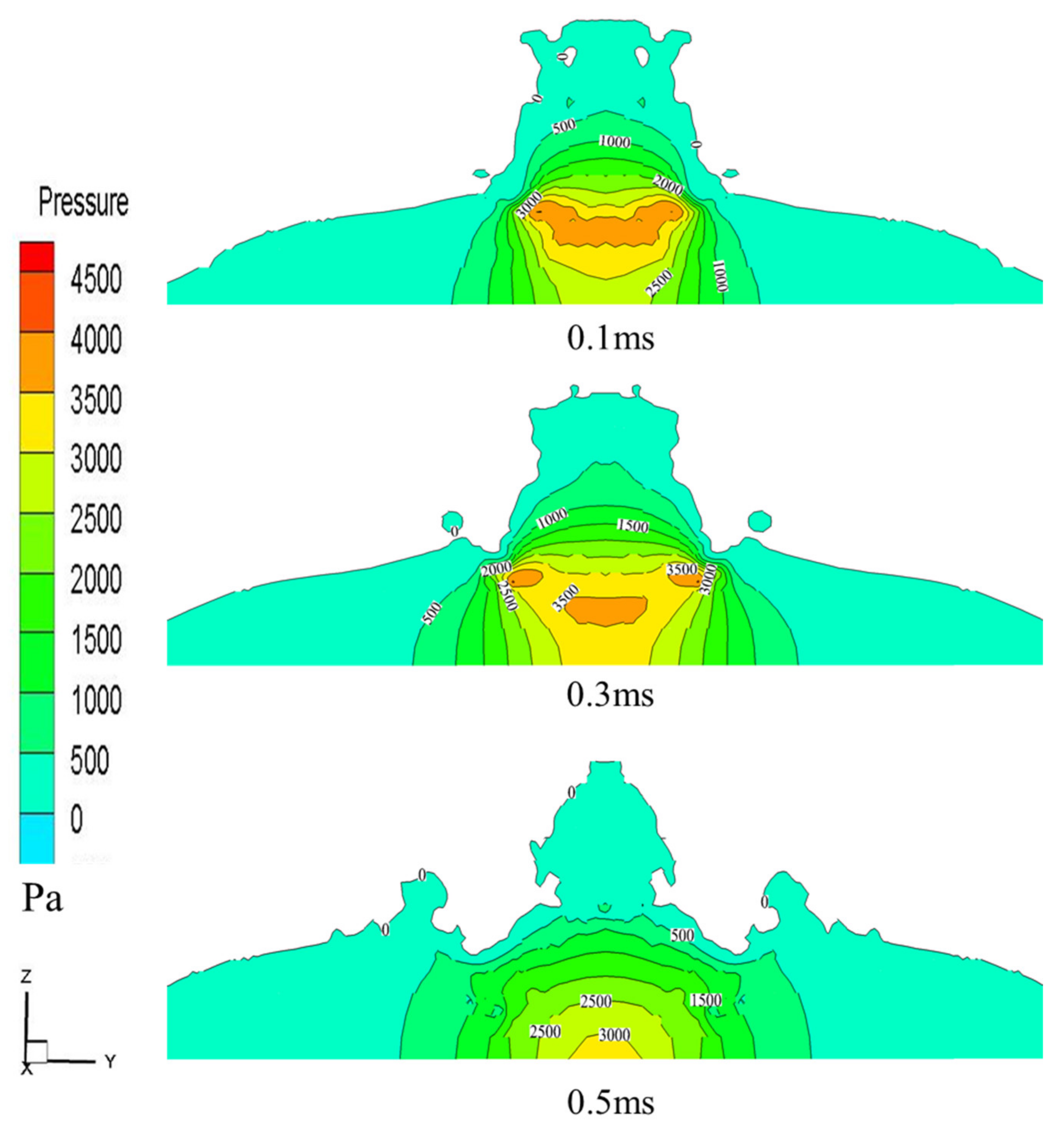
It can be seen from the pressure contour in Figure 4 that high pressure is generated at the initial stage of the collision between the droplet and the liquid film, as shown in Figure 4 at 0.1 ms. As the droplet continues to impinge on the liquid film, the pressure gradually transfers to the area around the impingement and to the bottom of the solid wall, leading to a gradual decrease in the fluid pressure (0.3 ms to 0.5 ms in Figure 4). The pressure on the free surface of the liquid film is close to the atmospheric pressure, while the pressure in the area of the impact neck is much greater. A large pressure gradient is formed between the interior and the surface of the impact neck area, which causes the liquid film to be ejected immediately from the neck area, resulting in the evolution and formation of the crown.
3.2. Analysis of the Influence of Different Weber Numbers on Droplet Impact on Liquid Film
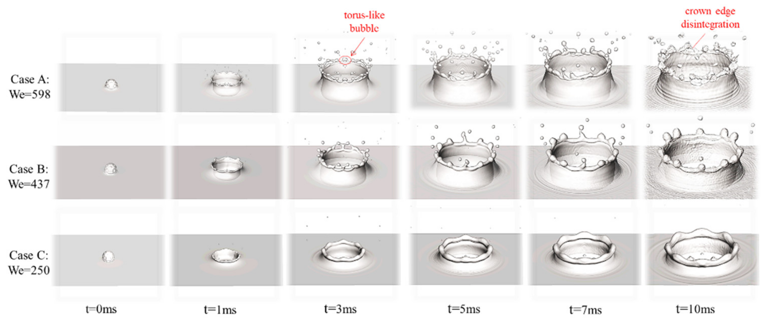
The three-dimensional evolution of the droplets impacting on the film at different times for cases A, B, and C is shown in Figure 5. It can be seen that the splash phenomena could be observed under all working conditions, which agrees with the experimental results conducted by Yarin and Weiss [6] and Cossali et al. [4]. They predicted that the critical Weber number for deposition and splashing is about 200. In this article, the Weber numbers of all operating conditions are 598, 437, and 250, respectively. Therefore, the satellite droplets would fall off the crown edge to cause splashing, and thus secondary droplets are formed. For our considered working conditions, secondary droplets are formed in the jetting stage, which corresponds to prompt splash. It can also be noted in Figure 5 that as the number of collision Weber increases, the number of secondary droplets falling off the edge of the crown gradually increases. In addition, when t = 3 ms in case A, the tip of the jet can be reconnected with the free surface of liquid film, thereby forming a torus-like bubble, which was verified by experiment of Weiss and Yarin [13].
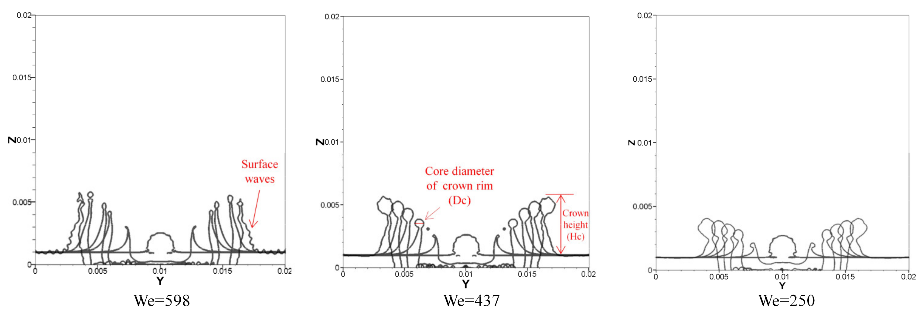
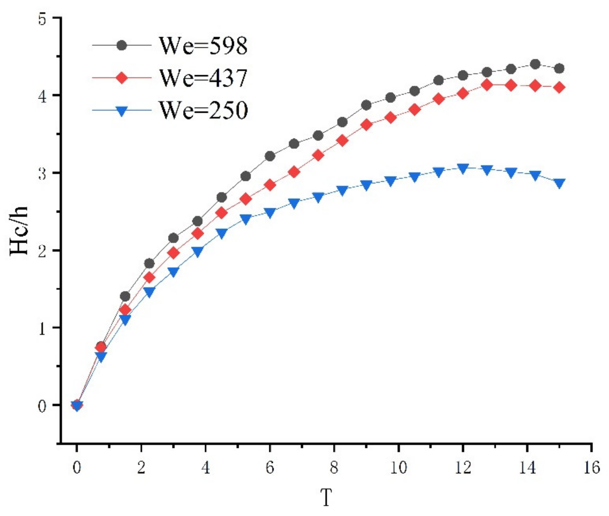
Figure 6 and Figure 7 shows the evolution of the x = 0.01 m crown section over time under different collision Weber numbers. It can be roughly seen from the Figure 6 that both the diameter of the crown and the height of the crown gradually increase during the growth of the crown. However, as shown in Figure 7, the height of the crown increases with the increase of Weber number. The core diameter of the crown rim is inversely proportional to the Weber number. Moreover, the crown thickness decreases as the impact Weber number increases, which can be used to explain the phenomenon of droplet splash caused by crown edge instability. As the Weber number increases, the droplet would hit the film with more energy, and thus more of the film would be squeezed to produce an upward motion of the jet source, resulting in the increase in the crown height. During the growth of the crown, the jet source is affected by gravity and surface tension. In the process of upward movement, the decrease in crown thickness and the increase in crown rim diameter are attributed to a lesser amount of liquid film being injected. The thinner the thickness of the crown, the smaller the diameter of the crown, and as a result, the crown rim behaves with less stability. Therefore, when the Weber number is large, the number of secondary splash droplets falling off the crown rim is also large. Figure 7 shows the relationship between the dimensionless crown height and dimensionless time under three different Weber numbers.
As can be seen from Figure 7, when the Weber number increases, the height of the dimensionless crown gradually increases with the dimensionless time, and as time progresses, the difference in the dimensionless height of the crown between different Weber numbers also increases gradually.
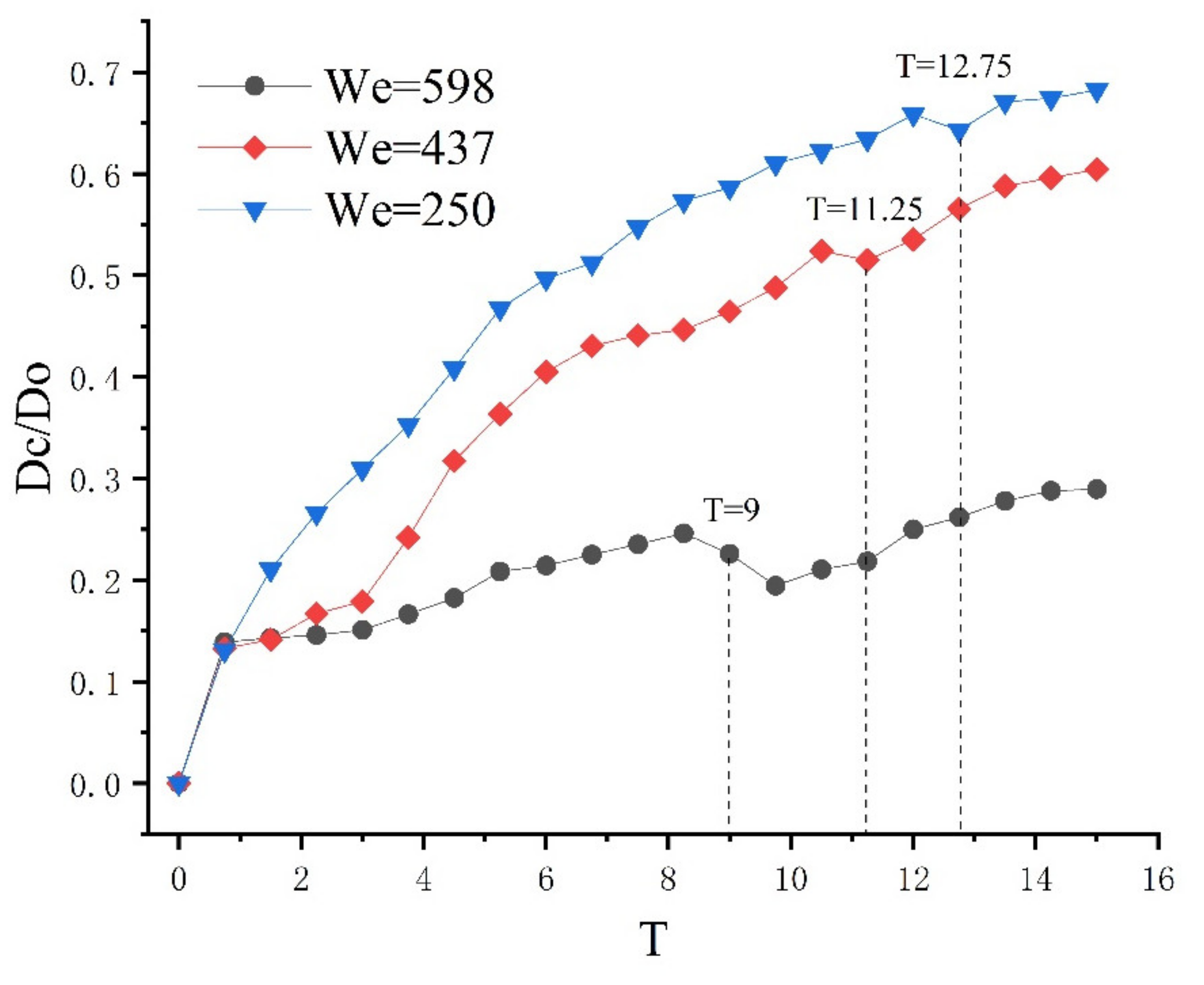
As shown in Figure 8, the dimensionless rim diameter of the crown decreases as the Weber number increases. As the diameter of the dimensionless crown edge decreases, the droplets fall off the crown edge at this time, and a droplet splash occurs. The larger the Weber number, the shorter the dimensionless time for splashing. For example, when We = 598, T = 9; when We = 437, T = 11.25; and when We = 250, T = 12.75.
3.3. Analysis of the Influence of Different Thicknesses of Film on Droplet Impingment
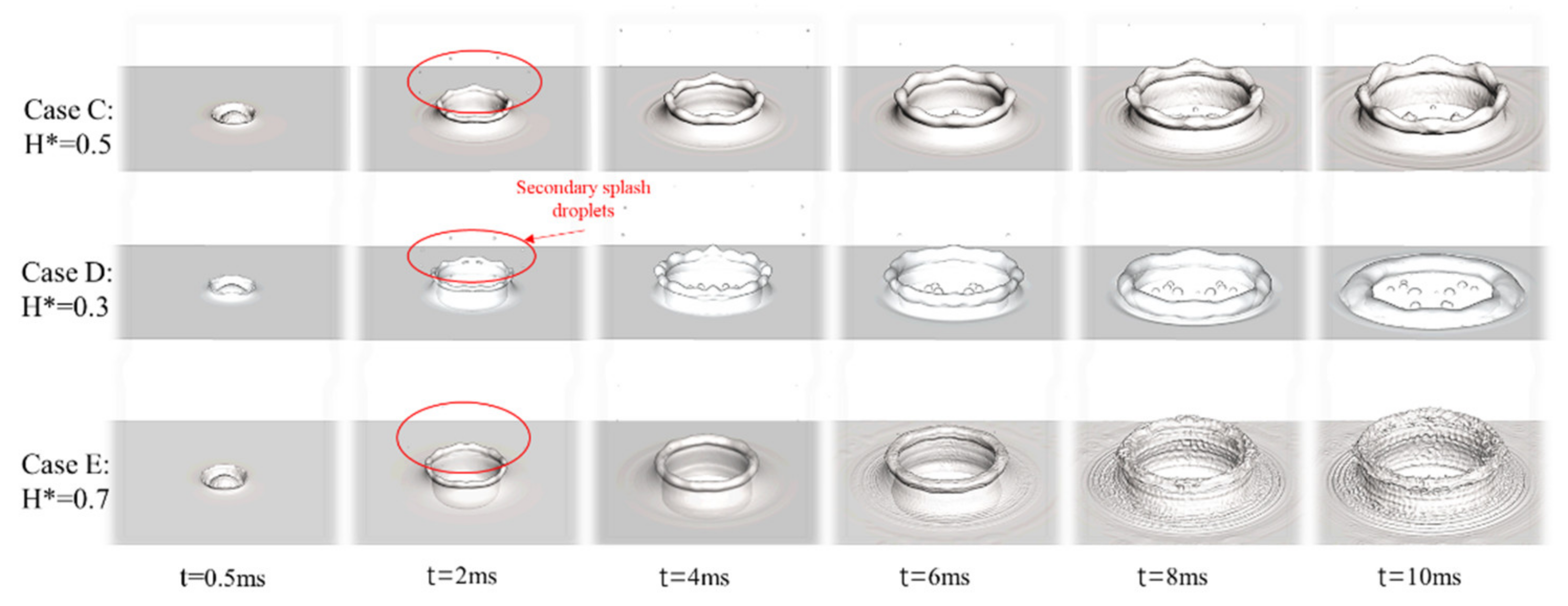
Figure 9 shows the three-dimensional evolution of the droplet impacting on the film at different times for the cases C, D, and E. It can be seen that when t = 2 ms, the number of secondary splash droplets is six in three different dimensionless liquid film thicknesses, meaning that the thickness of liquid film would not affect the generation of secondary splash droplets. However, when the thickness of the liquid film decreases, the evolution period of the crown shortens, and the collapse rate becomes faster. When the dimensionless liquid film thickness H* = 0.3, the crown is already in a collapsed state at t = 4 ms. When the dimensionless liquid film thicknesses are H* = 0.5 and H* = 0.7, the crown is still growing, as the droplet continues to impact the solid surface under the liquid film. As the thickness of the liquid film decreases, more energy is consumed when the droplet impacts the solid surface. Therefore, the jet energy for forming the crown is reduced and it is more likely for the crown to collapse.
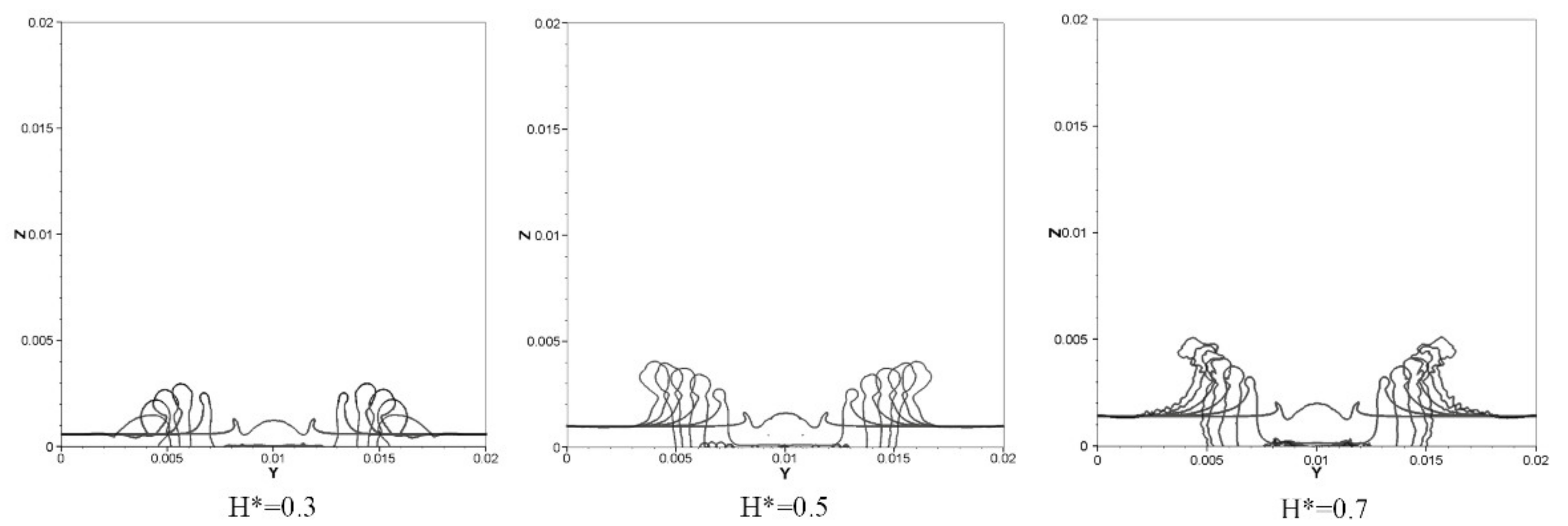
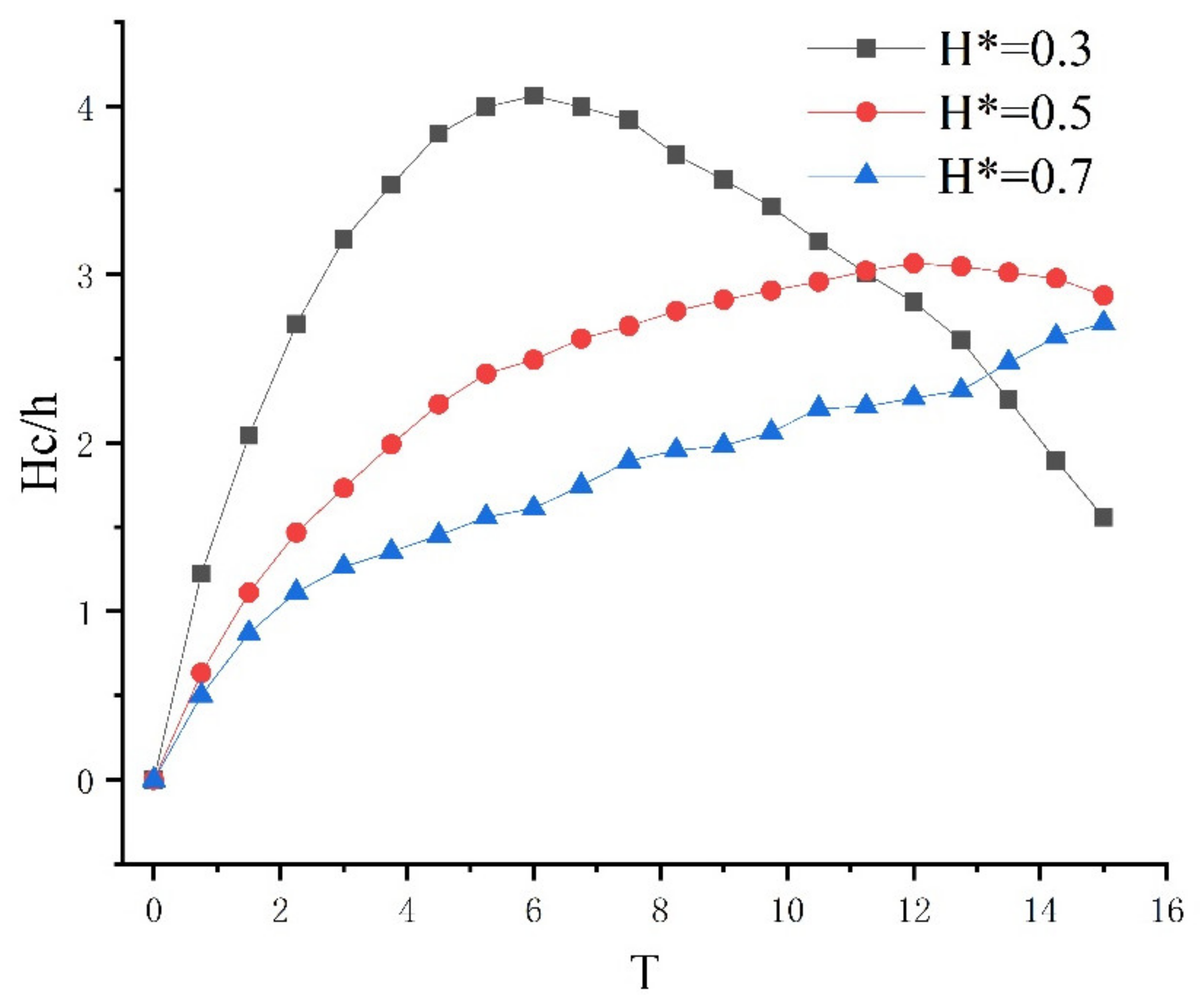
The evolutions of the x = 0.01 m crown section over time under different dimensionless liquid film thicknesses H* are as shown in Figure 10. It could be concluded that when the liquid film thickness increases, the crown height seems to increase slightly. However, according to Figure 11, the dimensionless crown height (Hc/h) decreases with the increase in the dimensionless liquid film thickness (H*), and when the thickness of the liquid film decreases, the dimensionless crown height (Hc/h) collapses in a shorter dimensionless time (T).
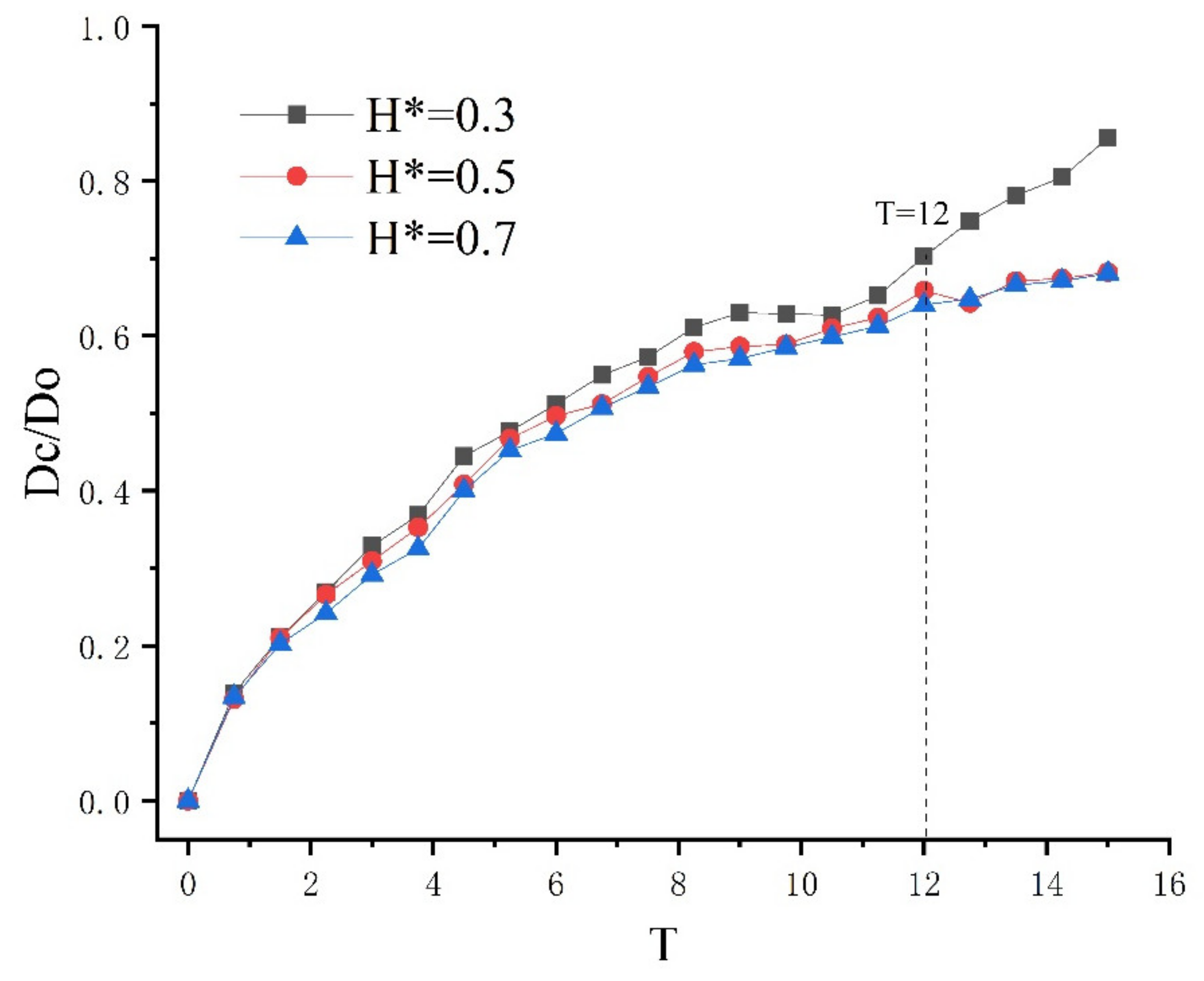
The dimensionless crown rim diameter changes with dimensionless time under different H*, as shown in Figure 12, from which it could be found that the liquid film thickness has almost no effect on the rim diameter of the crown before T = 12. However, when dimensionless time T is larger than 12, the difference in the crown rim diameter between different film thicknesses is more obvious.
4. Conclusions
In this paper, three-dimensional numerical simulations of single-droplet vertical splashing on the liquid film are carried out by the coupling of the finite volume method of Navier–Stokes equations and the VOF method. The relationship between the diameter of the free rim and the height of the crown and the impact velocity and the thickness of the liquid film is investigated. The main conclusions are as follows:
- The crown height increases with the Weber number, and the diameter of the crown rim is inversely proportional to the number of impact Weber when other operating parameters remain the same;
- The thinner the thickness of the crown is, the smaller the diameter of the crown is and the lower the stability of the crown rim. Therefore, when the Weber number is larger, the number of secondary splash droplets formed from the crown edge would also increase;
- The height of the dimensionless crown decreases with the increase in the dimensionless thickness of the liquid film, which has little effect on the diameter of the crown rim during the growth of the crown;
- The thickness of the liquid film does not affect the generation of secondary splash droplets. However, when the thickness of the liquid film decreases, the evolution period of the crown would be shortened and the collapse speed would become faster.
Author Contributions
Conceptualizaizion, Investigation, Formal analysis, Y.J.; Software, Writing—original draft, Visualization, H.Z.; writing—review and editing, L.Z.; data curation, Z.L. All authors have read and agreed to the published version of the manuscript.
Funding
The research was funded by the Key Research and Development Program of Zhejiang Province, grant number 2019C03117.
Institutional Review Board Statement
Not applicable.
Informed Consent Statement
Not applicable.
Data Availability Statement
Not applicable.
Acknowledgments
The authors gratefully acknowledge the financial supports from the Key Research and Development Program of Zhejiang Province (No.2019C03117).
Conflicts of Interest
The authors declare that they have no known competing financial interests or personal relationships that could have appeared to influence the work reported in this paper.
Nomenclature
| FVS | finite volume solution |
| VOF | volume of fluid |
| D0 | initial droplet diameter |
| U0 | velocity of droplet |
| h | liquid film thickness |
| H* | non-dimensional liquid film thickness |
| t | time |
| T | non-dimensional time |
| Κ | curvature of the interface region |
| stress tensor | |
| volumetric force | |
| velocity vector | |
| gravitational constant | |
| ▽ | del operator |
| Greek symbols | |
| ρ | density |
| σ | surface tension |
| μ | dynamic viscosity |
| α | volume fraction |
References
- Li, H.; Fang, W.; Li, Y.; Yang, Q.; Li, M.; Li, Q.; Feng, X.-Q.; Song, Y. Spontaneous droplets gyrating via asymmetric self-splitting on heterogeneous surfaces. Nat. Commun. 2019, 10, 1–6. [Google Scholar] [CrossRef] [PubMed] [Green Version]
- Coghe, A. A first study about single drop impingement on thin liquid film in a low Laplace number range. In Proceedings of the 11th European Conference of ILASS-Europe, Nürnberg, Germany, 21–23 March 1995; pp. 285–293. [Google Scholar]
- Liang, G.; Ya-Li, G. Analysis of liquid sheet and jet flow mechanism after droplet impinging onto liquid film. Acta Phys. Sin. Chin. Ed. 2013, 62, 024705. [Google Scholar] [CrossRef]
- Cossali, G.E.; Coghe, A.; Marengo, M. The impact of a single drop on a wetted solid surface. Exp. Fluids 1997, 22, 463–472. [Google Scholar] [CrossRef]
- Gueyffier, D.; Zaleski, S. Finger formation during droplet impact on a liquid film. Comptes Rendus Académie Sci. Ser. IIB Mech. Phys. Astron. 1998, 326. [Google Scholar]
- Yarin, A.L.; Weiss, D.A. Impact of drops on solid surfaces: Self-similar capillary waves, and splashing as a new type of kinematic discontinuity. J. Fluid Mech. 1995, 283, 141–173. [Google Scholar] [CrossRef]
- Rioboo, R.; Bauthier, C.; Conti, J.; Voue, M.; De Coninck, J. Experimental investigation of splash and crown formation during single drop impact on wetted surfaces. Exp. Fluids 2003, 35, 648–652. [Google Scholar] [CrossRef]
- Wal, R.L.V.; Berger, G.M.; Mozes, S.D. Droplets splashing upon films of the same fluid of various depths. Exp. Fluids 2006, 40, 33–52. [Google Scholar]
- Hao, J. Effect of surface roughness on droplet splashing. Phys. Fluids 2017, 29, 122105. [Google Scholar] [CrossRef]
- Okawa, T.; Kubo, K.; Kawai, K.; Kitabayashi, S. Experiments on splashing thresholds during single-drop impact onto a quiescent liquid film. Exp. Therm. Fluid Sci. 2020, 121, 110279. [Google Scholar] [CrossRef]
- Naveen, P.T.; Simhadri, R.R.; Ranjith, S.K. Simultaneous Effect of Droplet Temperature and Surface Wettability on Single Drop Impact Dynamics. Fluid Dyn. 2020, 55, 640–652. [Google Scholar] [CrossRef]
- Harlow, F.H.; Shannon, J.P. The Splash of a Liquid Drop. J. Appl. Phys. 1967, 38, 3855–3866. [Google Scholar] [CrossRef]
- Weiss, D.A.; Yarin, A.L. Single drop impact onto liquid films: Neck distortion, jetting, tiny bubble entrainment, and crown formation. J. Fluid Mech. 1999, 385, 229–254. [Google Scholar] [CrossRef]
- Shi, Z.Y.; Yan, Y.H.; Yang, F.; Qian, Y.H.; Guo-Hui, H.U. A lattice boltzmann method for simulation of a three-dimensional drop impact on a liquid film. J. Hydrodyn. Ser. B 2008, 20, 267–272. [Google Scholar] [CrossRef]
- Wu, J.; Liu, C.; Zhao, N. Dynamics of falling droplets impact on a liquid film: Hybrid lattice Boltzmann simulation. Colloids Surf. A Physicochem. Eng. Asp. 2015, 472, 92–100. [Google Scholar] [CrossRef]
- Raman, K.; Jaiman, R.; Lee, T.; Low, H. On the dynamics of crown structure in simultaneous two droplets impact onto stationary and moving liquid film. Comput. Fluids 2015, 107, 285–300. [Google Scholar] [CrossRef]
- Raman, K.A.; Jaiman, R.K.; Lee, T.-S.; Low, H.-T. Dynamics of simultaneously impinging drops on a dry surface: Role of impact velocity and air inertia. J. Colloid Interface Sci. 2017, 486, 265–276. [Google Scholar] [CrossRef] [PubMed]
- Guo, J.-H.; Dai, S.-Q. Numerical simulation on the mechanism of the normal impact of two droplets onto a thin film. J. Shanghai Univ. 2007, 11, 210–212. [Google Scholar] [CrossRef]
- Rieber, M.; Frohn, A. A numerical study on the mechanism of splashing. Int. J. Heat Fluid Flow 1999, 20, 455–461. [Google Scholar] [CrossRef]
- Guo, Y.; Wei, L.; Liang, G.; Shen, S. Simulation of droplet impact on liquid film with CLSVOF. Int. Commun. Heat Mass Transf. 2014, 53, 26–33. [Google Scholar] [CrossRef]
- Nikolopoulos, N.; Theodorakakos, A.; Bergeles, G. Three-dimensional numerical investigation of a droplet impinging normally onto a wall film. J. Comput. Phys. 2007, 225, 322–341. [Google Scholar] [CrossRef]
- Gupta, G.; Kumar, P. Splashing dynamics of a drop impact onto a deep liquid pool with moving film interface. Phys. Fluids 2020, 32, 012102. [Google Scholar] [CrossRef]
- Yuan, H.; Li, J.; He, X.; Chen, L.; Wang, Z.; Tan, J. Study of droplet splashing on a liquid film with a tunable surface tension pseudopotential lattice Boltzmann method. AIP Adv. 2020, 10, 025209. [Google Scholar] [CrossRef]
- Hirt, C.; Nichols, B. Volume of fluid (VOF) method for the dynamics of free boundaries. J. Comput. Phys. 1981, 39, 201–225. [Google Scholar] [CrossRef]
- Patankar, S.V.; Spalding, D.B. A calculation procedure for heat, mass and momentum transfer in three-dimensional parabolic flows. J. Heat Mass Transf. 1972, 15, 1787–1806. [Google Scholar] [CrossRef]
- Jasak, H. Error Analysis and Estimation for the Finite Volume Method with Applications to Fluid Flows; Imperial College London: London, UK, 1996; pp. 46–51. [Google Scholar]
- Ubbink, O.; Issa, R.I. A Method for Capturing Sharp Fluid Interfaces on Arbitrary Meshes. J. Comput. Phys. 1999, 153, 26–50. [Google Scholar] [CrossRef] [Green Version]
- Theodorakakos, A.; Bergeles, G. Simulation of sharp gas–liquid interface using VOF method and adaptive grid local refinement around the interface. Int. J. Numer. Methods Fluids 2004, 45, 421–439. [Google Scholar] [CrossRef]
- Okawa, T.; Shiraishi, T.; Mori, T. Production of secondary drops during the single water drop impact onto a plane water surface. Exp. Fluids 2006, 41, 965. [Google Scholar] [CrossRef]
Figure 1.
(a) The computational domain; (b) different levels of the adaptive grid in X = 0.01 m plan.
Figure 1.
(a) The computational domain; (b) different levels of the adaptive grid in X = 0.01 m plan.

Figure 2.
Numerical simulation results of the droplet splash process under two different levels of local refinement. (a) Simulation of a droplet splashing with four levels of local refinement (locref = 4) and (b) simulation of a droplet splashing with three levels of local refinement (locref = 3).
Figure 2.
Numerical simulation results of the droplet splash process under two different levels of local refinement. (a) Simulation of a droplet splashing with four levels of local refinement (locref = 4) and (b) simulation of a droplet splashing with three levels of local refinement (locref = 3).

Figure 3.
The velocity vector diagrams after a droplet impacts on liquid film at x = 0.01 m section.
Figure 3.
The velocity vector diagrams after a droplet impacts on liquid film at x = 0.01 m section.

Figure 4.
The pressure contour of a droplet’s initial impact on the liquid film at x = 0.01 m section.
Figure 4.
The pressure contour of a droplet’s initial impact on the liquid film at x = 0.01 m section.

Figure 5.
The three-dimensional evolution of the droplets impacting on the film at different times for case A, B, and C.
Figure 5.
The three-dimensional evolution of the droplets impacting on the film at different times for case A, B, and C.

Figure 6.
The evolution of x = 0.01 m section of the crown at different We.

Figure 7.
The dimensionless crown height changing with dimensionless time under three different Weber numbers.
Figure 7.
The dimensionless crown height changing with dimensionless time under three different Weber numbers.

Figure 8.
The dimensionless crown rim diameter changing with dimensionless time under three different Weber numbers.
Figure 8.
The dimensionless crown rim diameter changing with dimensionless time under three different Weber numbers.

Figure 9.
The three-dimensional evolution of the droplet impacting on the film at different times for case C, D, and E.
Figure 9.
The three-dimensional evolution of the droplet impacting on the film at different times for case C, D, and E.

Figure 10.
The evolution of x = 0.01 m section of the crown at different H*.

Figure 11.
The dimensionless crown height changing with dimensionless time under different H*.

Figure 12.
The dimensionless crown rim diameter changing with dimensionless time under different H*.
Figure 12.
The dimensionless crown rim diameter changing with dimensionless time under different H*.


Table 1.
Detailed grid parameters.
| Different Levels of Local Refinement | The Total Number of Computational Cells | Number of Liquid Film Cells | Number of Droplet Cells | Minimum Grid Volume (m3) |
|---|---|---|---|---|
| 0 (base grid) | 103,031 | 100,000 | 6024 | 8 × 10⁻¹² |
| 2 | 1,383,298 | 239,860 | 21,896 | 1 × 10⁻¹² |
| 3 | 2,825,118 | 799,160 | 101,040 | 1.25 × 10⁻¹³ |
| 4 | 8,759,226 | 3,035,996 | 491,112 | 1.56 × 10⁻¹⁴ |
| 5 | 32,866,422 | 11,982,528 | 2,206,504 | 1.95 × 10⁻¹⁵ |
Table 2.
Simulated operating condition parameter.
| Case | V (m/s) | H (mm) | H* | We | Re | Oh | Dimensions of Solution Domain |
|---|---|---|---|---|---|---|---|
| A | 4.64 | 1 | 0.5 | 598 | 9236 | 0.00264 | 10D0 × 10D0 × 10D0 |
| B | 3.97 | 1 | 0.5 | 437 | 7902 | 0.00264 | 10D0 × 10D0 × 10D0 |
| C | 3 | 1 | 0.5 | 250 | 5971 | 0.00264 | 10D0 × 10D0 × 10D0 |
| D | 3 | 0.6 | 0.3 | 250 | 5971 | 0.00264 | 10D0 × 10D0 × 10D0 |
| E | 3 | 1.4 | 0.7 | 250 | 5971 | 0.00264 | 10D0 × 10D0 × 10D0 |
Publisher’s Note: MDPI stays neutral with regard to jurisdictional claims in published maps and institutional affiliations. |
© 2021 by the authors. Licensee MDPI, Basel, Switzerland. This article is an open access article distributed under the terms and conditions of the Creative Commons Attribution (CC BY) license (https://creativecommons.org/licenses/by/4.0/).
Share and Cite
MDPI and ACS Style
Jin, Y.; Zhou, H.; Zhu, L.; Li, Z. Dynamics of Single Droplet Splashing on Liquid Film by Coupling FVM with VOF. Processes 2021, 9, 841. https://doi.org/10.3390/pr9050841
AMA Style
Jin Y, Zhou H, Zhu L, Li Z. Dynamics of Single Droplet Splashing on Liquid Film by Coupling FVM with VOF. Processes. 2021; 9(5):841. https://doi.org/10.3390/pr9050841
Chicago/Turabian StyleJin, Yuzhen, Huang Zhou, Linhang Zhu, and Zeqing Li. 2021. "Dynamics of Single Droplet Splashing on Liquid Film by Coupling FVM with VOF" Processes 9, no. 5: 841. https://doi.org/10.3390/pr9050841
Note that from the first issue of 2016, this journal uses article numbers instead of page numbers. See further details here.