Parametric Dimensional Analysis on a C-H2 Smelting Reduction Furnace with Double-Row Side Nozzles

State Key Laboratory of Advanced Special Steel, Shanghai Key Laboratory of Advanced Ferrometallurgy, School of Materials Science and Engineering, Shanghai University, Shanghai 200444, China
*
Author to whom correspondence should be addressed.
Processes 2020, 8(2), 129; https://doi.org/10.3390/pr8020129
Submission received: 12 November 2019
/
Revised: 9 January 2020
/
Accepted: 14 January 2020
/
Published: 21 January 2020
(This article belongs to the Special Issue Process Modeling in Pyrometallurgical Engineering)
Abstract
:Higher requirements for steel smelting technology have been put forward based on the increasing awareness of energy conservation and environmental protection. In the field of iron making, carbon reduction processes are often used. In this study, molten iron was smelted by designing a C-H2 smelting reduction method. Although previous researchers have studied this through a large number of physical and numerical simulations, they have not yet refined general laws from the perspective of dimensional analysis. In this paper, a double-row side blow hydraulics simulation was carried out in the C-H2 smelting reduction furnace, and an entire list of dimensionless groups of input and output parameters was proposed based on its hydraulics simulation data. The expressions between the dimensionless group of mixing time and dimensionless groups such as Capillary number (Ca) and Lagrange group (La1) were obtained by multiple linear regression based on the experimental research results and data analysis. By verifying the calculated and experimental values of the dimensionless group of mixing time, it can be seen that both have a good positive correlation. This study provides a better methodology for controlling key parameters and lays the foundation for the optimal design of the process parameters for the C-H2 smelting reduction furnace.
1. Introduction
The steel industry is one of the most important raw material industries. The iron-making process in the early steel process is mainly done through a blast furnace [1]. With changes in the times, a series of drawbacks of the blast furnace have gradually emerged. One is the heavy dependence on coke resources [2], and the second is the increasing pressure on environmental protection. With the rapid depletion of natural resources and awareness regarding environmental protection, the smelting reduction process came into being. This significantly reduces energy consumption and investment by recycling the waste heat and eliminating sintering and coking plants [3]. Among the variants of this process, representative ones are COREX [4], jointly developed by VAI and Korf, FINEX [5], jointly developed by POSCO Steel and VAI Engineering, HISMELT [6], jointly developed by CRA Australia and Kloekner, and DIOS [7], jointly developed by the Japan Iron and Steel Federation to organize eight domestic steel companies.
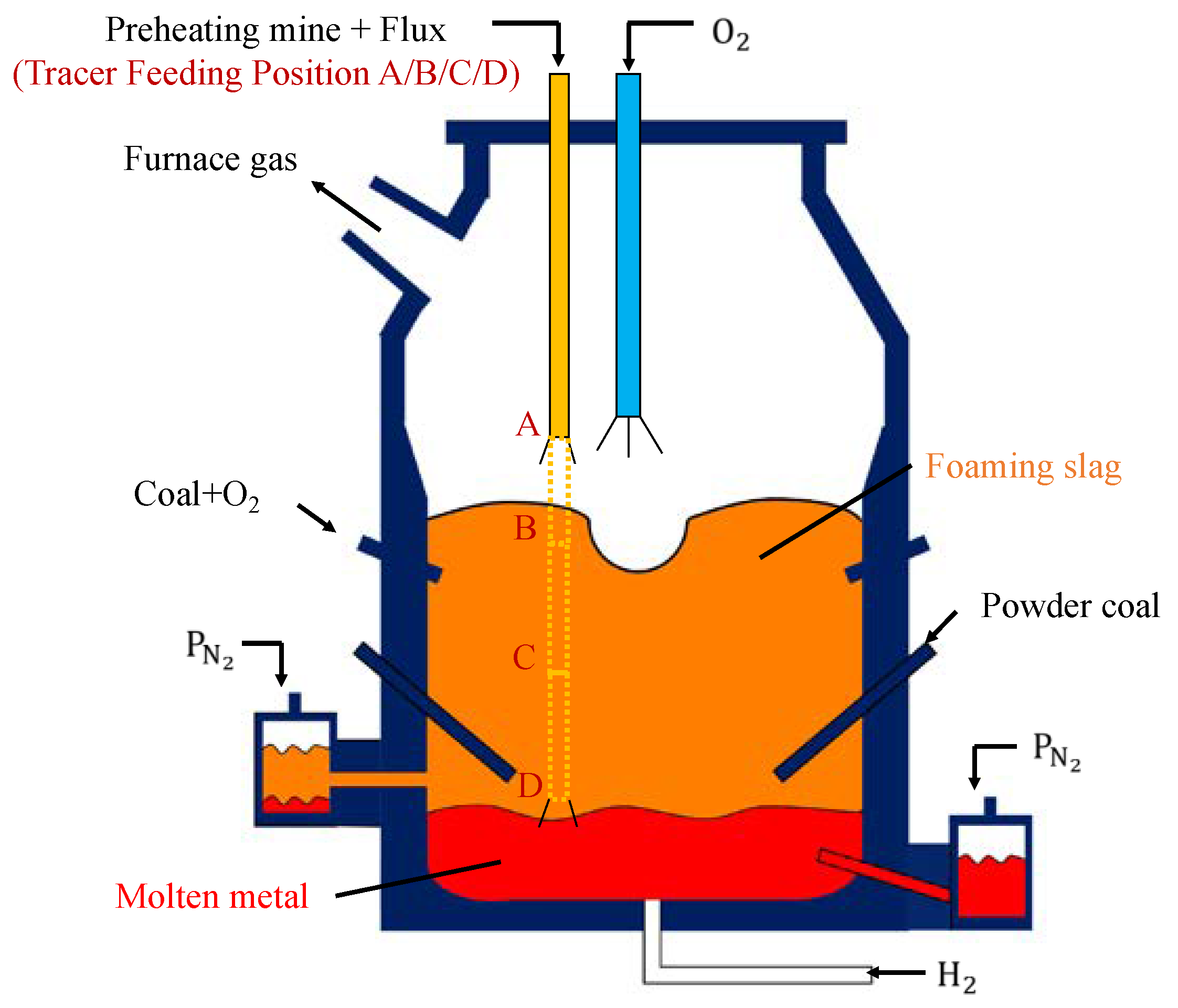
In the field of smelting reduction, many researchers have done considerable research on physical simulation and mathematical simulation. Zou et al. [8,9] proposed a two-step three segment iron bath smelting reduction process with a thick slag layer, which was developed for the gradient separation of the oxidation zone and the reduction zone by a thick slag layer with physical simulation. Srishilan et al. [10] proposed a predictive thermochemical model of the COREX process which enables the rapid computation of process parameters. The model helps in predicting the variations in process parameters with respect to the degree of metallization and post-combustion ratio for the given raw material conditions. A series of recent representative research results have also been obtained in smelting reduction and hydrocarbon reduction. In the field of plasma reduction, for example, Behera et al. [11] succeeded in the smelting reduction of iron ore (hematite) in thermal hydrogen plasma. Mandal et al. [12] described a new concept for maintaining an inert atmosphere with a high temperature of about 1973 K (1700 °C) inside the furnace during smelting reduction. In terms of direct reduction, Shim et al. [13] reported that the direct reduction rate in a melter–gasifier was roughly drawn as the product of the CO2 content in the ascending gas and the reaction rate constant of coal with CO2, and the way to minimize the direct reduction ratio was discussed with that diagram. You et al. [14] used Sn-bearing complex iron ore via reduction with mixed H2/CO gas to prepare Sn-enriched direct reduced iron (DRI). In the behavior of reduction, Park et al. [15,16] investigated the high-temperature behavior of a magnetite–coke composite pellet fluxed with dolomite by a customized thermogravimetric analyzer (TGA) at 1573 K (1300 °C) and the influence of different coal types on the reduction of the composite pellet. At the same time, previous research has proposed a new generation of C-H2 smelting reduction furnace (cf. Figure 1).
The theory of similarity is the theory of experimentation. For the formulas of complex phenomena that cannot be solved by mathematical analysis, the similarity theory provides an experimental solution. The similar first theorem specifies the physical quantities that need to be measured during the experiment, as well as the conditions that the model experiment should follow. The π theorem is a universal dimensional analysis method which was proposed by E. Buckinghan in 1915, so it is also known as the Buckingham Theorem. The Buckingham Theorem is described as F(x1, x2, …, xn) = 0, if there are n variables that are mutual functions for a physical phenomenon. If these variables contain m basic quantities, they can be arranged into the functional relation φ(π 1, π 2, …, π n ≤ m) of (n ≤ m) dimensionless numbers, and then n physical quantities can be combined into (n ≤ m) dimensionless π numbers. In this paper, the dimensional analysis is based on the Buckingham theorem, which specifies how to organize the experimental results. The experimental results need to be organized into a functional relationship between dimensionless groups. Finally, the dimensionless groups and the coefficients of similarity are determined according to the experimental results. The similarity theory is used to solve the problem in various fields. Zhen et al. [17] focuses on providing a quantitative methodology on how each parameter affects the structural response of the subsurface tension leg platform (STLP), which will facilitate establishing the unique design dimensionless groups as regards to STLP. Vatankhah et al. [18] predicted the rate of discharge through different side holes in irrigation and hydraulic engineering. Sharp-crested side triangular orifices were studied experimentally and analytically, and several models were derived for the discharge coefficient based on Buckingham’s theorem of dimensional analysis. Meng et al. [19] used the π theorem, an improved dimensional analysis method, and the dimensionless quantity, which can effectively reflect the relationship between the non-sinusoidal vibration parameters of a continuous casting mold, was given. The dimensionless function correlation formula, which can objectively describe the actual phenomenon, was obtained.
Side blowing is one of the key processes of smelting reduction. Fuel and enriched oxygen are injected into the furnace by a side nozzle to provide the heat required for the reduction reaction and the melt is stirred at the same time. By designing and optimizing the parameters such as the arrangement, the angle, and the flow rate of the side nozzle, this provides better reaction conditions for melting in the furnace and prolongs the service life of the side nozzle, and finally achieves the combination with the top and bottom blowing. For side blowing, many scholars had conducted relevant research in this field. For example, Feng [20] outlined the production overview of the side-blown melting reduction furnace, introduced the construct design of main components, and listed the practice and summarized the characteristics of the side-blown reduction furnace. Due to a large number of side nozzle parameters and furnace parameters, the experimental results were not regular on the surface, so it was necessary to sort out the data through dimensional analysis and provide an analytical formula, so as to obtain the quantitative law. Wang et al. [21] investigated the penetration behavior of immersion side-blowing gas flow in a slag lade water model by photography and the dimensional analysis method, in order to provide a theoretical base for improving the reaction speed between the gas–liquid interface and the oxygen gun jet distribution. The maximum penetration depth calculated by the empirical formula is in agreement with the measured data from the experiments.
Although many studies [22,23,24] have been carried out on the C-H2 smelting reduction furnace through physical simulation and mathematical simulation, the experimental data and results have not been quantitatively analyzed. This paper is aimed at providing a quantitative method for examining how each parameter affects the mixing time in the C-H2 smelting reduction furnace, and proposes a dimensionless input and output parameter based on the Buckingham theory, a complete list of derived dimensionless groups. This is helpful for establishing a single design standard for C-H2 smelting reduction furnaces. This study provides a means to understand critical parameters better and lays the foundation for the optimal design of the side blowing parameters of the C-H2 smelting reduction furnace. The conclusions obtained are also widely applicable to the engineering design and design analysis of the smelting reduction furnace.
2. Experimental Setup and Methods
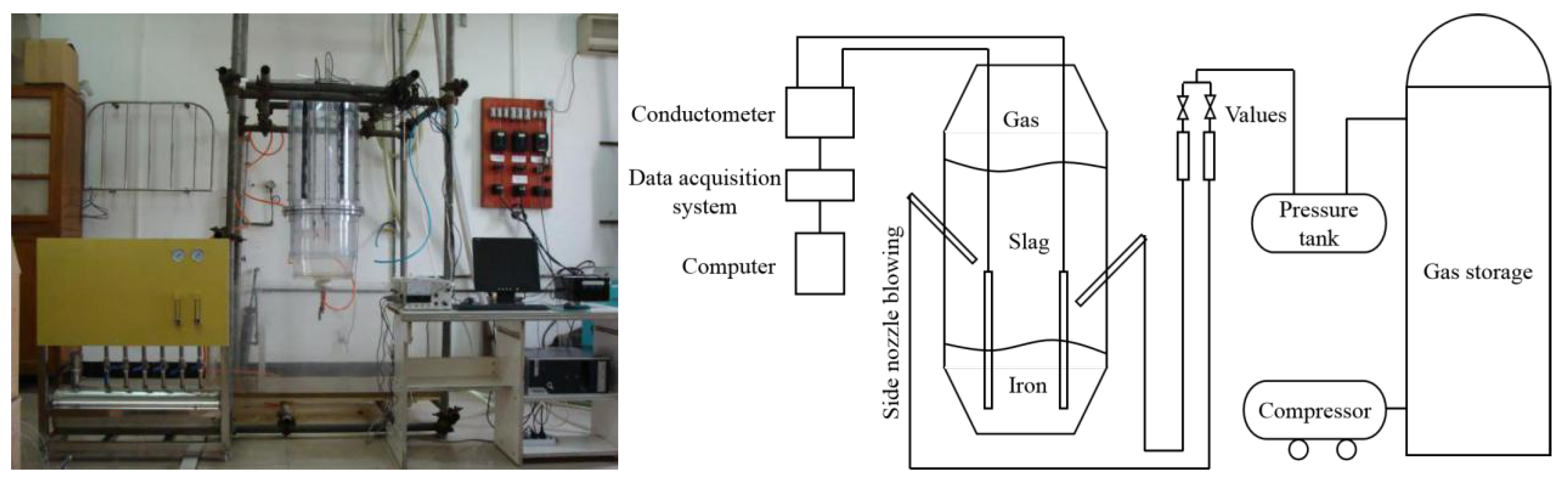
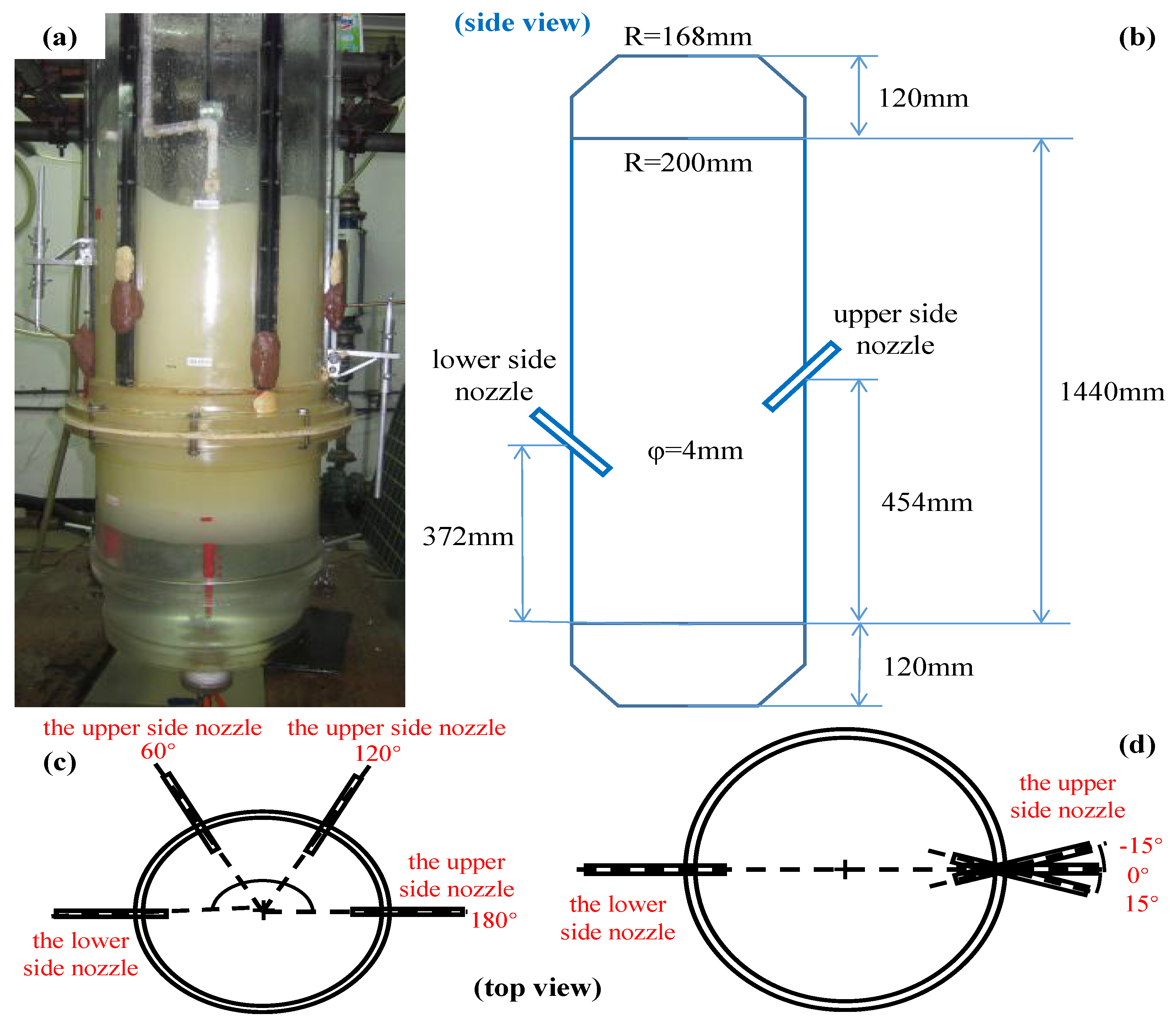
In this paper, a comprehensive experimental study on the flow characteristics of a C-H2 smelting reduction furnace was carried out. Based on the similarity principle, the smelting reduction iron-making process under the high temperature conditions in the prototype was studied by hydraulic simulation at room temperature in this experiment. The schematic diagram of the C-H2 smelting reduction model apparatus is shown in Figure 2. The model was simulated by the scale ratio of 1:1 to the prototype, in which the molten iron of the prototype was 200 kg. The experiment was carried out in a cylindrical transparent plexiglass furnace with a diameter of about 0.4 m and a height of 1.68 m. In the experiment, the molten iron was simulated by water, high vacuum oil was used to simulate the slag, and oxygen-enriched air was blown on the top and bottom and side nozzle to simulate the flux injection and the bottom blowing hydrogen. The volume ratio of water to high vacuum oil in the model was 1:2 [25,26], in which the water phase was 0.246 m and the height of the oil phase was 0.492 m. The physical parameters of the experiment are shown in Table 1. In the prototype, the combined top, bottom, and side blowing of the C-H2 smelting reduction process occurs. This paper is the first phase of the project, aiming to carry out the physical simulation and dimensional analysis of the single-side blowing of double-row side nozzles. The side blowing nozzle was divided into the upper side nozzle and the lower side nozzle, and the diameter of the side nozzle was 0.004 m. The upper side nozzle was 0.574 m from the bottom and was located at 1/3 above the slag phase. The lower side nozzle was 0.492 m from the bottom and was located in the middle of the slag layer. The prototype and dimensions of the water model are shown in Figure 3a,b, respectively.
In this study, several different influencing factors were set. The effects of various factors and mixing time were obtained by orthogonal tests. By sorting out the experimental data, it was organized to be a functional relationship between the dimensionless groups. The first factor was the tracer feeding position. In the prototype, the tracer feeding port was added to the preheating mine and flux. It is of considerable significance to investigate the feeding position of raw materials for the mixing effect in the molten pool. Position A was at 2 cm above the slag interface (0.758 m from the bottom). Position B was located at 2 cm below the slag interface (0.718 m from the bottom). Position C was at the center of the slag (0.492 m from the bottom). Position D was located at 2 cm above the slag and the molten interface (0.266 m from the bottom), as shown in Figure 4a.
Similarly, several other factors were considered separately. These included the relative angle between the upper side nozzle and the lower side nozzle (60°, asymmetrical side blowing; 120°, asymmetrical side blowing; 180°, symmetric side blowing) (cf. Figure 3c), the horizontal angle of the upper side nozzle and the lower side nozzle (−15°, 0°, 15°) (cf. Figure 3d), the insertion depth of the side nozzle, and the flow rate of the side nozzle.
The inside of the molten pool was strongly agitated and disturbed in the combined upper side nozzle and lower side nozzle. Therefore, the efficiency of mass transfer and heat transfer was increased, and the rate of chemical reaction was also increased. In order to study the mixing phenomenon in the C-H2 smelting reduction bath, the mixing time was regarded as an important index. The mixing time [27] was defined as the period required for an instantaneous tracer concentration to settle within ±5% deviation around the final tracer concentration in the C-H2 smelting reduction reactor bath. This definition is referred to as the 95% mixing time. In the C-H2 smelting reduction bath, the mixing time was measured by the conductivity of three electrodes, which was 0.05 m away from the bottom of the bath. Figure 4b is the position and angle of the sensor and tracer. In the prototype, the feed port was used for feed preheating ore and flux. In this experiment, in order to simulate the effect of different raw material positions on the mixing time of the molten pool, a saturated Sodium chloride (NaCl) aqueous solution (75 mL) was fed from the intermediate to the C-H2 smelting reduction furnace. The conductivity of water was measured by three DSS-IIA conductivity meters and recorded automatically by a computer software recorder. For each physical simulation test site in each mode of operation, the measurements were taken at least three times and the arithmetic mean of the average residence time was obtained. Through the orthogonal test and analysis, the relationship between the average residence time and various experimental parameters can be obtained. These results would eventually be organized into a functional relationship between the dimensionless groups.
3. Dimensional Analysis
The purpose of this study was to establish a relationship between the mixing time and other valid variables. Their dimensions were considered through dimensional analysis. In this method, the first step is to select the appropriate initial parameters, including the input parameters and output parameters of the mixing time. The second step is to group these initial parameters into a dimensionless group and organize the new relationships between the various parameters. In particular, it is important to select the initial parameters precisely, since there is a need for a unique relationship between the chosen parameters [28,29].
Several factors may affect the value of mixing time. The variables that may affect the mixing time are density ρ, kinematic viscosity υ, surface tension σ, stirring energy ε [30], etc. In this study, 20 initial parameters were selected to identify the dimensionless groups of the parameters which can quantify the mixing time, as shown in Table 2. Based on this, 17 corresponding dimensionless groups were obtained from the selected initial parameters, according to the Vaschy–Buckingham theorem.
The mixing time can be represented by the following functional relationships:
Meanwhile, since many factors are constant in this study, such as the height of the furnace, the height of the high vacuum oil, the height of the side nozzle, the diameter of the side nozzle and so on, the functional relationships can be further simplified to
The equation can be expressed in the following dimensionless equation:
where π1~π8 is a dimensionless group, and is a functional symbol. After substituting in each variable, it gives
By replacing the other variables with ρ, Ds and Vs, we get
Since the side-blown nozzle is located in the high vacuum oil, the kinematic viscosity here is selected as the high vacuum oil kinematic viscosity, voil, m2·s−1. The tracer feeding position and the insertion position of the side nozzle are closely related to the total height of the water phase and oil phase, the DS in the tracer feeding position number and the insertion depth number of side nozzle are replaced by the total height of the water phase and oil phase Hoil+w, which can be converted into the following equation:
In this work, the angle between the upper side nozzle and the lower side nozzle is also a relatively important factor, including the relative angle and horizontal angle, so the angle factor should be taken into account when studying the dimensionless groups. The momentum dimensionless group is studied based on different angles. δ is introduced here, that is,
where is combined the the relative angle between the upper side nozzle and the lower side nozzle and the horizontal angle of the upper side nozzle and the lower side nozzle. This parameter synthetically considers the influence of flow velocity with various angles, Vs is flow velocity of the side nozzle, m·s−1. Df is the diameter of the furnace, m, and Qs is the volumetric flow rate, m3·s−1.
Through the above dimensionless group derivation, a series of dimensionless groups can be obtained as follows in Table 3.
The original dimensionless groups mentioned above can be substituted into Equation (10) to obtain
Extracting the τ from Equation (10) and rearranging, we get
where υoil is the kinematic viscosity of the high vacuum oil, m2·s−1, σ is the surface tension of the high vacuum oil, kg·s−2, g is the acceleration of gravity, m·s−2, ε is the stirring energy of the side nozzle, kg·m2·s−3, δ is the dimensionless groups of momentum, qs is the flow rate of the single side nozzle, m3·s−1, hs is the insertion depth of the side nozzle, m, Hoil+w is the total height of the high vacuum oil and water, m, Ds is the diameter of the single side nozzle, m, and Vs is the flow velocity of the side nozzle, m·s−1.
The dimensionless groups related to Equation (11) based on a physical chemistry handbook are shown in Table 4:
Combining Table 3 and Table 4, the dimensionless groups in Equation (11) can be sorted into Table 5.
Based on the fact that is constant in this condition, it will be removed here. At the same time, Njm is named in order to simplify the expression of , that is . According to Table 3, Table 4 and Table 5 and the actual working conditions of this study, the equation of dimensionless groups can be expressed as follows:
As can be seen from Table 4, is a constant. Since Ca is the dimensionless group representing the relative effect of viscous drag forces versus surface tension forces acting across an interface between a liquid and a gas, or between two immiscible liquids, so the Capillary number (Ca) is retained here, thus the following dimensionless groups equation can be further obtained:
where a, b, c, d, e, and f are the empirical coefficient, to be derived from the experimental data.
Through the analysis of the data obtained in the hydraulic simulation experiment, the influence of the dimensionless quantities and the mixing time was obtained.
4. Results and Discussions
In this study, multiple linear regression was used to fit the dimensionless groups equation in order to obtain many empirical coefficients in Equation (13). Comparing the calculated value of the fitted dimensionless groups equation with the water simulation experiment value allowed us to verify the accuracy. The multiple linear regression equation of dimensionless groups can be rewritten into the following mode:
4.1. The Effects of Ca and La1
After the parameters such as the injection velocity of the upper side nozzle and the lower side nozzle are respectively substituted into Equation (14), the data of multiple linear regression are shown in the Table 6:
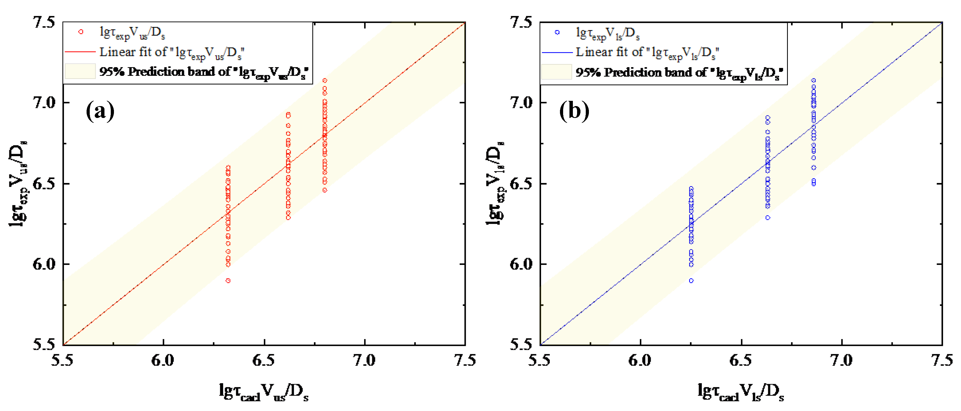
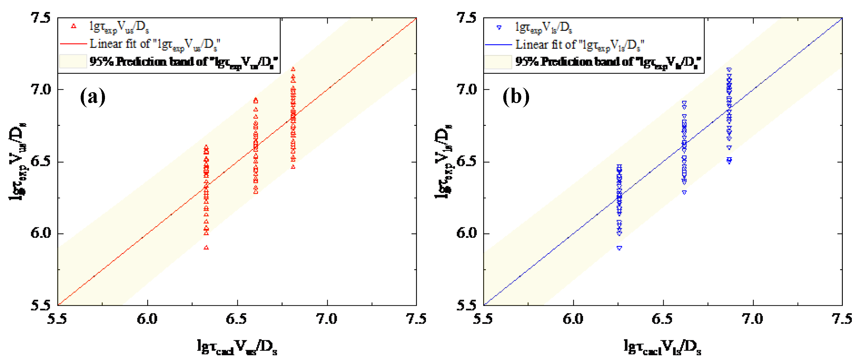
From Table 6, the equation of the mixing time of the upper side nozzle and the lower side nozzle and the similar number of Ca, La1 can be obtained, respectively:
where Vus is the injection velocity of the upper side nozzle, m·s−1, Vls is the injection velocity of the lower side nozzle, m·s−1.
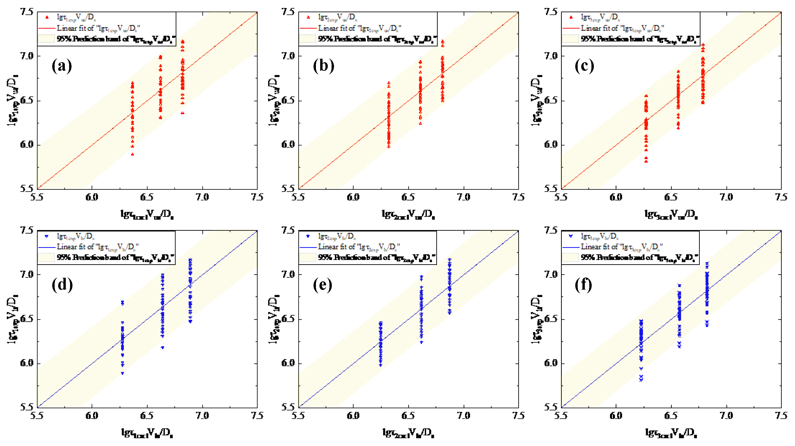
Figure 5a,b shows the relationship between the experimental value and the calculated value of the dimensionless group of the mixing time of the upper side nozzle and the lower side nozzle, respectively, made according to the Equations (15) and (16). As can be seen from Figure 5a,b, for both the upper side nozzle and the lower side nozzle, the experimental values have a considerable linear relationship with the calculated values. At the same time, to further verify the comparison, Figure 6a–f shows the relation diagram of the experimental value and the calculated value of the mixing time dimensionless groups in three monitoring points τ1, τ2 and τ3 of the upper and lower side nozzle, respectively. It can also be seen that it has a higher consistency with the τ (cf. Figure 5).
.
4.2. The Effects of Ca, La1 and Njm
After studying the effect of Ca and La1, the Njm dimensionless group is added here for the purpose of investigating the relationship between the dimensionless group of the mixing time and the dimensionless groups such as density, dynamic viscosity, stirring energy, flow rate, and so on based on the variable of velocity. The following table contains the multiple linear regression data based on the three dimensionless numbers of upper side nozzle and lower side nozzle, respectively:
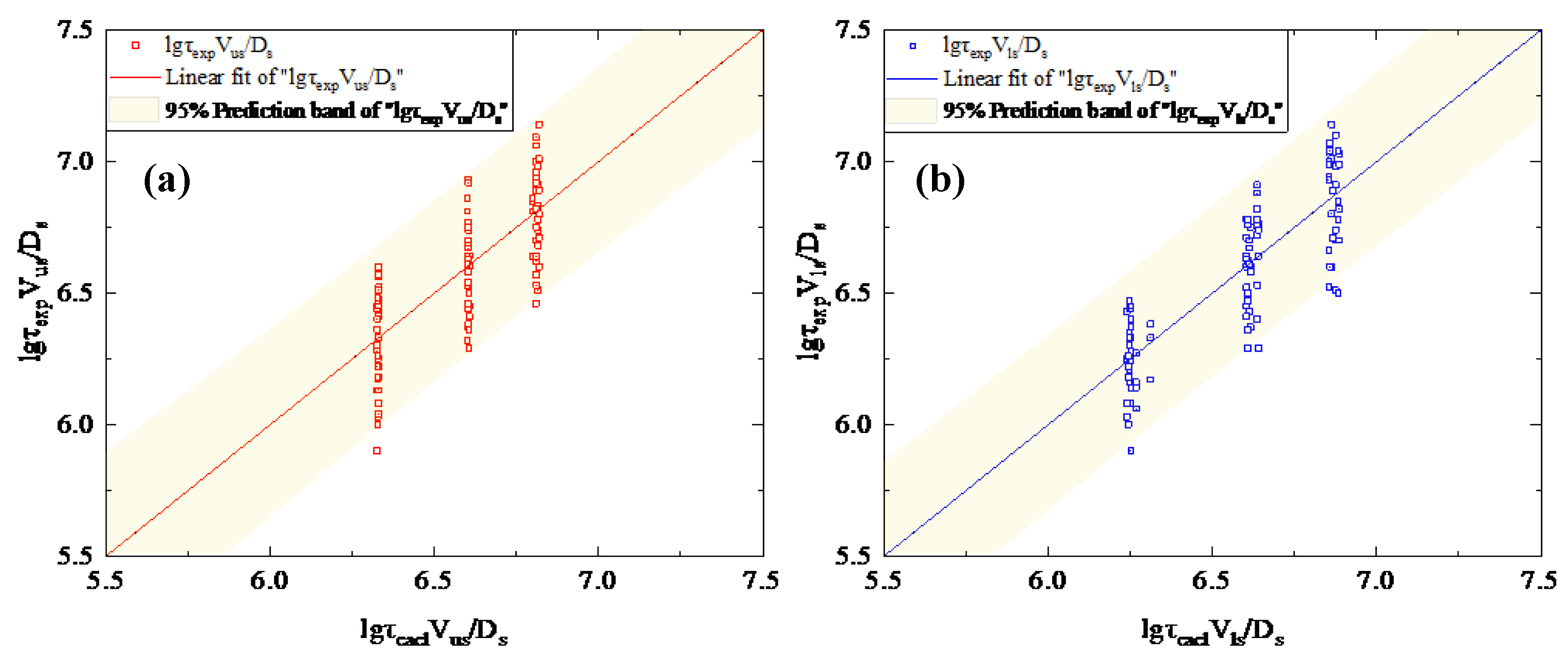
From Table 7, the equations between the dimensionless group of the mixing time and the three dimensionless groups of Ca, La1 and Njm for the upper and lower side nozzles can be obtained, respectively, as shown below:
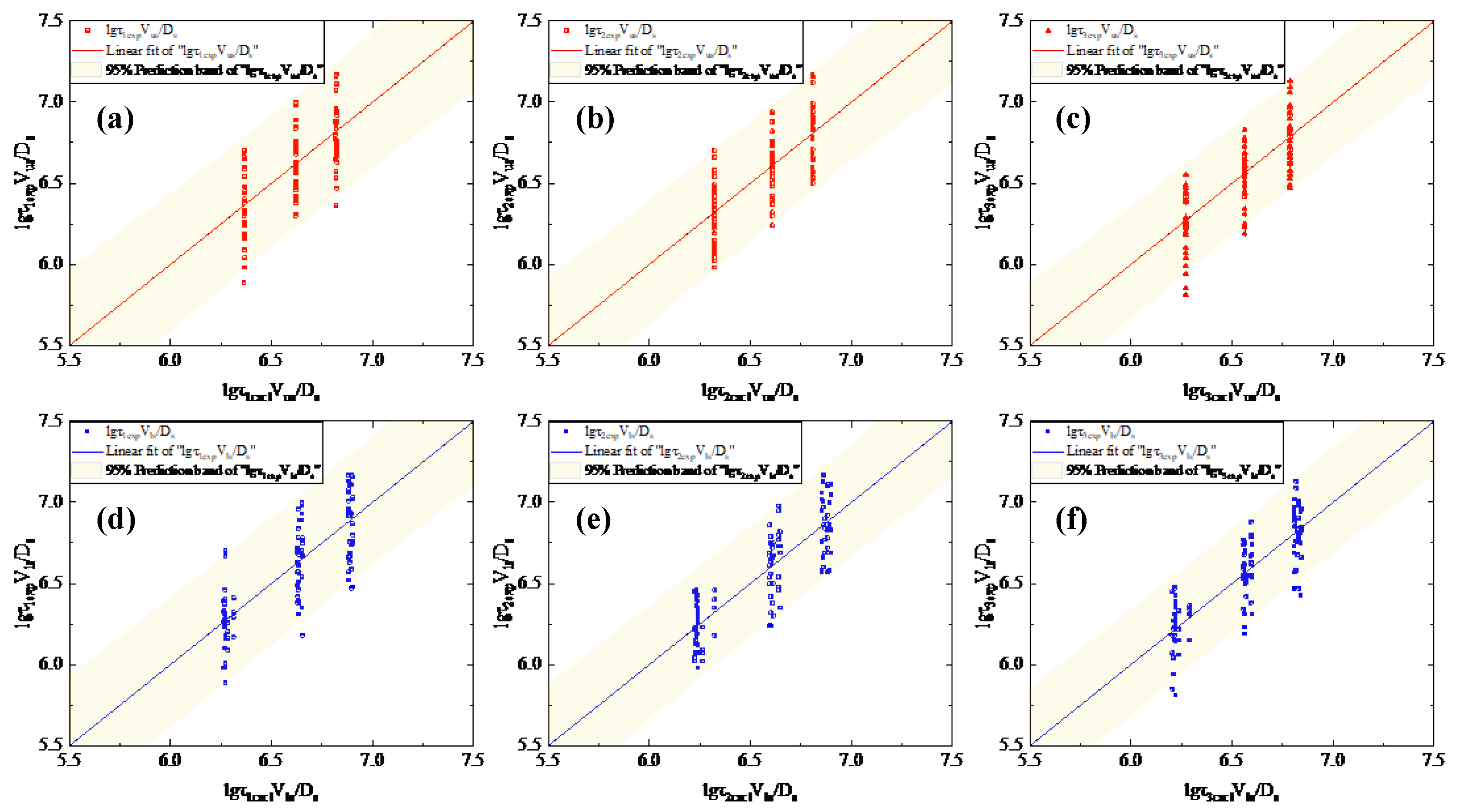
Similarly, by drawing the experimental values and calculated values for the dimensionless group of mixing time, we can see from Figure 7a,b that they have a good linear correlation, and the comparison chart (cf. Figure 8a–f) of τ1, τ2, τ3 is also shown a high consistency with τ (cf. Figure 7), respectively.
4.3. The Effects of Ca, La1, Njm, and δ
The above three dimensionless groups are mainly based on the variable factor of injection velocity. Nevertheless, the variables of the angles are also important variable parameters, such as the relative angle of the upper and lower side nozzle, the horizontal angle of the upper side nozzle, the horizontal angle of the lower side nozzle, etc. and dimensionless group δ is the group of the related angle. Therefore, the dimensionless group δ is introduced here to study the expression of the dimensionless group of mixing time under the action of these four dimensionless groups. The following Table 8 shows multiple linear regression data for the experimental values of four dimensionless groups to the mixing time:
Based on the data in Table 8, the following equations of the mixing time dimensionless group of the upper side nozzle and the mixing time dimensionless group of the lower side nozzle can be obtained, respectively:
Finally, by comparing the experimental values of the dimensionless group of mixing time with the calculated value of the dimensionless group, it can be seen that the experimental value of the dimensionless group has a good linear relationship with the calculated value of the dimensionless group (cf. Figure 9a,b), and it can also be seen from Figure 10a–f that there is a high consistency between the figure τ1, τ2, τ3 (cf. Figure 10) and τ (cf. Figure 9).
4.4. The Effects of Ca, La1, Njm, δ, Hi and hi
The position of the tracer feeding position and the insertion depth of the side nozzle are also important variable parameters. The expression of the dimensionless group of mixing time was studied after adding these two dimensionless groups. On the basis of the above dimensionless groups, the dimensionless group related to the tracer feeding position and the dimensionless group related to the insertion depth of the side nozzle was added unceasingly into the equation of mixing time dimensionless group. After substituting the parameters such as the flow velocity of upper side nozzle and the insertion depth of upper side nozzle into the Equation (14), multiple linear regression was performed through the origin, and the results are shown in in Table 9:
As can be seen from Table 9, the equation of the dimensionless group of the mixing time of the upper side nozzle is as follows in Equation (21):
Similarly to the upper side nozzle, Table 9 can also be obtained after the injection velocity and insertion depth of the lower side nozzle are replaced in the Equation (14) by multiple linear regression. According to the data in Table 9, the equation of the dimensionless group of mixing time of lower side nozzle can be obtained in Equation (22).
By comparing the dimensionless group calculated by the dimensionless Equations (21) and (22) with the dimensionless groups measured in the experiment, the correctness of the above dimensionless group can be verified. Figure 11a shows the relationship between the experimental value and the calculated value of the mixing time dimensionless group for the upper side nozzle, while Figure 11b shows the relationship between the experimental value and the calculated value of the mixing time dimensionless group for the lower side nozzle. It can be seen from Figure 11a,b that the fitting effect of a dimensionless group of mixing time is good. At the same time, in order to further verify its accuracy, Figure 12a–f shows the fitting curves of the three mixing time monitoring points at the respective operating conditions of the upper side nozzle and the lower side nozzle, respectively. It can also be seen that the distribution of the showcases 1, 2, and 3 has a relatively high degree of fitness. Therefore, it can be concluded that the equation of the mixing time dimensionless group of the upper side nozzle and the equation of the mixing time dimensionless group of the lower side nozzle have practical reference value.
5. Conclusions
Based on the experimental research and data analysis, the dimensionless groups of mixing time and kinetic viscosity, the surface tension, the tracer feeding position, the insertion depth of the side nozzle, etc., were obtained. In this paper, the expressions between the dimensionless group of mixing time and dimensionless groups such as Ca and La1 were obtained by multiple linear regression. It can be seen from the expressions that the indexes of the dimensionless groups have a higher identity when they have more than three dimensionless groups. By verifying the calculated and experimental values of the dimensionless group of mixing time, it can be seen that both have a good positive correlation. At the same time, it can also be seen from the comparison between the calculated values of τ1, τ2, τ3 and the experimental values that they are in good agreement with the corresponding τ, which indicates that the fitting expressions have higher reliability. Because density, surface tension, and other parameters of the medium have not been changed in this study, Equations (15) and (16) are more suitable for the study of the side nozzle velocity and related angle. Equations (21) and (22) will be of great significance when the density, viscosity, surface tension, and furnace diameter of the medium are changed in further work. This conclusion will better provide help for the control of key parameters, help to establish the design standard of C-H2 smelting reduction furnaces, and lay a foundation for the optimization of side nozzle parameters of C-H2 smelting reduction furnaces.
Author Contributions
Conceptualization, J.X. and J.Z.; Data curation, J.X. and J.Z.; Formal analysis, J.X.; Funding acquisition, J.Z.; Investigation, J.X. and J.Z.; Methodology, J.X., B.W., and J.Z.; Project administration, J.Z.; Resources, J.X., B.W., and J.Z.; Supervision, J.Z.; Validation, J.X., B.W., and J.Z.; Writing—original draft, J.X.; Writing—review and editing, J.X., B.W., and J.Z. All authors have read and agreed to the published version of the manuscript.
Funding
This study was funded by the National Science and Technology Support Program for development of smelting reduction iron smelting process based on hydrogen metallurgy (2006BAE03A12).
Acknowledgments
The authors gratefully acknowledge the resources partially provided by the State Key Laboratory of Advanced Special Steel, Shanghai University of Materials Science and Engineering.
Conflicts of Interest
The authors declare no conflict of interest.
References
- Tylecote, R.; Hua, J. History of Metallurgical Development in the World, 1st ed.; Beijing Science and Technology Literature Publishing House: Beijing, China, 1985; pp. 576–582. [Google Scholar]
- Chen, J.; Lin, W.; Zhao, J. Non-Coking Coal Metallurgy Technology, 1st ed.; Chemical Industry Press: Beijing, China, 2007; pp. 25–34. [Google Scholar]
- Mohsenzadeh, F.; Payab, H.; Abedi, Z.; Mohammad, A. Reduction of CO2 emissions and energy consumption by improving equipment in direct reduction ironmaking plant. Clean Technol. Environ. Policy 2019, 21, 847–860. [Google Scholar] [CrossRef]
- Ali, H.; Marlene, A.; Lynn, P. Alternative emerging ironmaking technologies for energy-efficiency and carbon dioxide emissions reduction: A technical review. Renew. Sustain. Energy Rev. 2014, 33, 645–658. [Google Scholar]
- You, Y.; Li, Y.; Luo, Z.; Lia, H.; Zou, Z.; Yang, R. Investigating the effect of particle shape on the charging process in melter gasifiers in COREX. Powder Technol. 2019, 351, 305–313. [Google Scholar] [CrossRef]
- Xu, C.; Cang, D. A brief overview of low CO2 emission technologies for iron and steel making. J. Iron Steel Res. Int. 2010, 17, 1–7. [Google Scholar] [CrossRef]
- Guo, Z.; Xie, Y.; Wang, D. Evaluation of sulfur distribution in the process of coal-based smelting reduction ironmaking. Energy Convers. Manag. 1997, 38, 1413–1419. [Google Scholar]
- He, Y.; Li, C.; Wei, G.; Zou, Z. Static model of iron bath smelting reduction process with thick slag layer. J. Northeast. Univ. Nat. Sci. 2015, 36, 651–654. [Google Scholar]
- Li, C.; He, Y.; Li, Q.; Zou, Z. Physical simulation of fluid mixing in a smelting reduction iron-bath with thick slag layer. J. Northeast. Univ. Nat. Sci. 2014, 35, 1266–1269. [Google Scholar]
- Srishilan, C.; Shukla, A. Static thermochemical model of COREX melter gasifier. Metall. Mater. Trans. B 2018, 49, 388–398. [Google Scholar] [CrossRef]
- Behera, P.; Bhoi, B.; Paramguru, R.; Mukherjee, P.; Mishra, B. Hydrogen plasma smelting reduction of Fe2O3. Metall. Mater. Trans. B 2018, 50, 262–270. [Google Scholar] [CrossRef]
- Mandal, A.; Sinha, O. Recovery of multi-metallic components from bottom ash by smelting reduction under plasma environment. Metall. Mater. Trans. B 2016, 47, 19–22. [Google Scholar] [CrossRef]
- Shim, Y.; Jung, S. Conditions for minimizing direct reduction in smelting reduction iron making. ISIJ Int. 2018, 58, 274–281. [Google Scholar] [CrossRef] [Green Version]
- You, Z.; Li, G.; Wen, P.; Peng, Z.; Zhang, Y.; Jiang, T. Reduction of Sn-bearing iron concentrate with mixed H2/CO gas for preparation of Sn-enriched direct reduced iron. Metall. Mater. Trans. B 2017, 48, 1486–1493. [Google Scholar] [CrossRef]
- Park, H.; Sohn, I.; Tsalapatis, J.; Sahajwalla, V. Reduction behavior of dolomite-fluxed magnetite: Coke composite pellets at 1573 K (1300 °C). Metall. Mater. Trans. B 2018, 49, 1109–1118. [Google Scholar] [CrossRef] [Green Version]
- Park, H.; Sohn, I.; Freislich, M.; Sahajwalla, V. Investigation on the reduction behavior of coal composite pellet at temperatures between 1373 and 1573 K. Steel Res. Int. 2017, 88, 1–13. [Google Scholar] [CrossRef]
- Zhen, X.; Wu, J.; Huang, Y.; Han, Y.; Yao, J. Parametric dimensional analysis on the structural response of an innovative subsurface tension leg platform in ultra-deep water. China Ocean Eng. 2018, 32, 482–489. [Google Scholar] [CrossRef]
- Vatankhah, A.; Mirnia, H. Predicting discharge coefficient of triangular side orifice under free fow conditions. J. Irrig. Drain. Eng. 2018, 144, 04018030. [Google Scholar] [CrossRef]
- Meng, X.; Zhu, M. Non-sinusoidal vibration parameter control of continuous casting mold based on dimensional analysis. Metal Ind. Autom. 2006, S2, 142–144. [Google Scholar]
- Feng, S. Design of side-blown melting reduction furnace and its application. China Nonferrous Metall. 2015, 3, 19–21. [Google Scholar]
- Wang, M.; Zhang, L.; Yu, S.; Tu, G.; Sui, Z. Penetration behaviour of immersion side-blowing airstream in molten bath. Nonferrous Met. 2006, 58, 50–52. [Google Scholar]
- Wang, Z.; Lei, M.; Zhang, J.; Zheng, S.; Wang, B.; Hong, X. Experimental study on fluid flow characteristics in the smelting reduction furnace by water model. Chin. J. Process Eng. 2009, 9, 36–40. [Google Scholar]
- Lei, M.; Zhang, J.; Wang, Z.; Wang, B.; Zheng, S.; Hong, X. Effect of side and top lance blowing on fluid flow in smelting reduction furnace. J. Chin. Rare Earth Soc. 2008, 26, 247–251. [Google Scholar]
- Yin, D.; Feng, K.; Cheng, W.; Wang, B.; Mao, J.; Xie, J.; Zhang, J.; Zheng, S.; Hong, X. Experimental study on side-blowing nozzles in smelting reduction furnace with water model. Chin. J. Process Eng. 2010, 10, 83–87. [Google Scholar]
- Meng, S.; Zhang, H. Simulation and analysis of molten reduction process in iron bath. Angang Technol. 1995, 11, 15–18. [Google Scholar]
- Dong, L.; Liu, Q. Present study status on the final reduction of iron bath smelting reduction. J. Iron Steel Res. 1999, 11, 65–69. [Google Scholar]
- Iguchi, M.; Nakamura, K.; Tsujino, R. Mixing time and fluid flow phenomena in liquids of varying kinematic viscosities agitated by bottom gas injection. Metall. Mater. Trans. B 1998, 29, 569–575. [Google Scholar] [CrossRef]
- Palmer, A. Dimensional Analysis and Intelligent Experimentation, 1st ed.; World Scientific Publishing: Singapore, 2008; pp. 38–49. [Google Scholar]
- Quéau, L.; Kimiaei, M.; Randolph, M. Dimensionless groups governing response of steel catenary risers. Ocean Eng. 2013, 74, 247–259. [Google Scholar] [CrossRef]
- Terrazas, M.; Conejo, A. Effect of nozzle diameter on mixing time during bottom-gas injection in metallurgical ladles. Metall. Mater. Trans. B 2015, 46, 711–718. [Google Scholar] [CrossRef]
- Robert, C.; Melvin, J.; William, H. Handbook of Chemistry and Physics, 66th ed.; CRC Press: Boca Raton, FL, USA, 1985; pp. 314–324. [Google Scholar]
Figure 1.
A new generation of C-H2 iron bath smelting reduction process configuration.

Figure 2.
Schematic diagram of the C-H2 smelting reduction model apparatus.

Figure 3.
Prototype (a) and dimensions (b) of water model, the relative angle between the upper side nozzle and the lower side nozzle (c), the horizontal angle of the upper side nozzle and the lower side nozzle (d).
Figure 3.
Prototype (a) and dimensions (b) of water model, the relative angle between the upper side nozzle and the lower side nozzle (c), the horizontal angle of the upper side nozzle and the lower side nozzle (d).

Figure 4.
Different tracer feeding positions (a), and the position and angle of the sensor and tracer (b).
Figure 4.
Different tracer feeding positions (a), and the position and angle of the sensor and tracer (b).

Figure 5.
Comparison of experimental lgτVs/Ds with calculated ones for upper side nozzle (a) and lower side nozzle (b), respectively, using proposed Equations (15) and (16).
Figure 5.
Comparison of experimental lgτVs/Ds with calculated ones for upper side nozzle (a) and lower side nozzle (b), respectively, using proposed Equations (15) and (16).

Figure 6.
Comparison of experimental lgτVs/Ds with calculated ones for upper side nozzle (a–c) and lower side nozzle (d–f), respectively, using .
Figure 6.
Comparison of experimental lgτVs/Ds with calculated ones for upper side nozzle (a–c) and lower side nozzle (d–f), respectively, using .

Figure 7.
Comparison of experimental lgτVs/Ds with calculated ones for upper side nozzle (a) and lower side nozzle (b), respectively, using proposed Equations (17) and (18).
Figure 7.
Comparison of experimental lgτVs/Ds with calculated ones for upper side nozzle (a) and lower side nozzle (b), respectively, using proposed Equations (17) and (18).

Figure 8.
Comparison of experimental lgτVs/Ds with calculated ones for upper side nozzle (a–c) and lower side nozzle (d–f) respectively using τ1, τ2, τ3.
Figure 8.
Comparison of experimental lgτVs/Ds with calculated ones for upper side nozzle (a–c) and lower side nozzle (d–f) respectively using τ1, τ2, τ3.

Figure 9.
Comparison of experimental lgτVs/Ds with calculated ones for upper side nozzle (a) and lower side nozzle (b), respectively, using proposed Equations (19) and (20).
Figure 9.
Comparison of experimental lgτVs/Ds with calculated ones for upper side nozzle (a) and lower side nozzle (b), respectively, using proposed Equations (19) and (20).

Figure 10.
Comparison of experimental lgτVs/Ds with calculated ones for upper side nozzle (a–c) and lower side nozzle (d–f), respectively, using τ1, τ2, τ3.
Figure 10.
Comparison of experimental lgτVs/Ds with calculated ones for upper side nozzle (a–c) and lower side nozzle (d–f), respectively, using τ1, τ2, τ3.

Figure 11.
Comparison of experimental lgτVs/Ds with calculated ones for upper side nozzle (a) and lower side nozzle (b), respectively, using proposed Equations (21) and (22).
Figure 11.
Comparison of experimental lgτVs/Ds with calculated ones for upper side nozzle (a) and lower side nozzle (b), respectively, using proposed Equations (21) and (22).

Figure 12.
Comparison of experimental lgτVs/Ds with calculated ones for upper side nozzle (a–c) and lower side nozzle (d–f), respectively, using τ1, τ2, τ3.
Figure 12.
Comparison of experimental lgτVs/Ds with calculated ones for upper side nozzle (a–c) and lower side nozzle (d–f), respectively, using τ1, τ2, τ3.


Table 1.
Physical parameters of the experiment.
| Density (kg/m3) | Kinematic Viscosity (m2/s) | |
|---|---|---|
| Iron | 7020 | 9 × 10⁻⁵ |
| Slag | 3000 | 1.33 × 10⁻⁴ |
| Air | 1.205 | 1.506 × 10⁻⁵ |
| High vacuum oil (25 °C) | 860 | 8.75 × 10⁻⁵ |
| Water | 1000 | 1 × 10⁻⁶ |
Table 2.
Selected parameters for the dimensional analysis of the mixing time.
| Category | Variable | Symbol | Unit | M | L | t |
|---|---|---|---|---|---|---|
| Physical Parameters | Density | ρ | kg·m−3 | 1 | −3 | 0 |
| Kinematic viscosity | υ | m2·s−1 | 0 | 2 | −1 | |
| Surface tension | σ | kg·s−2 | 1 | 0 | −2 | |
| Mixing time | τ | s | 0 | 0 | 1 | |
| Acceleration of gravity | g | m·s−2 | 0 | 1 | −2 | |
| Stirring energy | ε | kg·m2·s−3 | 1 | 2 | −3 | |
| Model Size | Height of furnace | Hf | m | 0 | 1 | 0 |
| Diameter of furnace | Df | m | 0 | 1 | 0 | |
| Height of high vacuum oil | Hoil | m | 0 | 1 | 0 | |
| Height of water | Hw | m | 0 | 1 | 0 | |
| Height of upper side nozzle | Hus | m | 0 | 1 | 0 | |
| Height of lower side nozzle | Hls | m | 0 | 1 | 0 | |
| Diameter of side nozzle | Ds | m | 0 | 1 | 0 | |
| Tracer Position | Height of tracer | Hi | m | 0 | 1 | 0 |
| Distance from tracer to the center of the circle | Ri | m | 0 | 1 | 0 | |
| Measuring Point | Height of measuring point | Hm | m | 0 | 1 | 0 |
| Distance from measuring point to the center of the circle | Rm | m | 0 | 1 | 0 | |
| Working Condition | Insertion depth of side nozzle | hs | m | 0 | 1 | 0 |
| Flow velocity of side nozzle | Vs | m·s−1 | 0 | 1 | −1 | |
| Flow rate of single side nozzle | qs | m3·s−1 | 0 | 3 | −1 |
In Table 2, M, L, t are three basic dimensions, where M stands for the mass dimension, kg, L for the length dimension, m, and t for the time dimension, s.
Table 3.
Expression of dimensionless groups based on Equations (8) and (9).
| Dimensionless Groups | Expressions |
|---|---|
Table 4.
The dimensionless groups associated with Equation (11) based on the physical chemistry handbook [31].
Table 4.
The dimensionless groups associated with Equation (11) based on the physical chemistry handbook [31].
| Symbol | Name | Expression |
|---|---|---|
| Re | Reynolds number | |
| Ca | Capillary number | |
| La1 | Lagrange group | |
| Ho1 | Homochronous number | |
| KF | Capillarity-buoyancy number | |
| Z | Ohnesorge number | |
| Diameter group | ||
| jM | J-factor | |
| Nsh | Sherwood number | |
| Nsc | Schmidt number |
Table 5.
The dimensionless groups in Equation (11).
| Dimensionless Groups | Expression |
|---|---|
Table 6.
Value and standard error of lg Ca and lg La1 by multiple linear regression for the upper side nozzle and lower side nozzle.
Table 6.
Value and standard error of lg Ca and lg La1 by multiple linear regression for the upper side nozzle and lower side nozzle.
| Y Axis | X Axis | Value | Standard Error | |
|---|---|---|---|---|
| Upper side nozzle | lgτexpVus/Ds | “lgCa” | −0.9564 | 0.0684 |
| “lgLa1” | −0.6496 | 0.0006 | ||
| Lower side nozzle | lgτexpVls/Ds | “lgCa” | −0.7403 | 0.0647 |
| “lgLa1” | −0.6685 | 0.0058 |
Table 7.
Value and standard error of lg Ca, lg La1, and lgNjm by multiple linear regression for upper side nozzle and low side nozzle.
Table 7.
Value and standard error of lg Ca, lg La1, and lgNjm by multiple linear regression for upper side nozzle and low side nozzle.
| Y Axis | X Axis | Value | Standard Error | |
|---|---|---|---|---|
| Upper side nozzle | lgτexpVus/Ds | “lgCa” | −1.8971 | 1.3603 |
| “lgLa1” | −2.6093 | 2.8302 | ||
| “lgNjm” | 5.0122 | 7.2387 | ||
| Lower side nozzle | lgτexpVls/Ds | “lgCa” | −1.5112 | 1.2876 |
| “lgLa1” | −2.2745 | 2.679 | ||
| “lgNjm” | −4.1078 | 6.8521 |
Table 8.
Value and standard error of lg Ca, lg La1, lg Njm and lg δ by multiple linear regression for the upper side nozzle and lower side nozzle.
Table 8.
Value and standard error of lg Ca, lg La1, lg Njm and lg δ by multiple linear regression for the upper side nozzle and lower side nozzle.
| Y Axis | X Axis | Value | Standard Error | |
|---|---|---|---|---|
| Upper side nozzle | lgτexpVus/Ds | “lgCa” | −1.8802 | 1.3685 |
| “lgLa1” | −2.7131 | 2.8806 | ||
| “lgNjm” | 5.3305 | 7.4090 | ||
| “lgδ” | 0.1140 | 0.5086 | ||
| Lower side nozzle | lgτexpVls/Ds | “lgCa” | −1.8503 | 1.3312 |
| “lgLa1” | −2.6127 | 2.7000 | ||
| “lgNjm” | 4.7726 | 6.8838 | ||
| “lgδ” | −0.4049 | 0.4034 |
Table 9.
Value and standard error of lg Ca, lg La1, lg Njm, lgδ, lgHi/(Hoil+w), and lg(hs/Hoil+w) by multiple linear regression for upper side nozzle and lower side nozzle.
Table 9.
Value and standard error of lg Ca, lg La1, lg Njm, lgδ, lgHi/(Hoil+w), and lg(hs/Hoil+w) by multiple linear regression for upper side nozzle and lower side nozzle.
| Y Axis | X Axis | Value | Standard Error | |
|---|---|---|---|---|
| Upper side nozzle | lgτexpVus/Ds | “lgCa” | −1.8704 | 1.2735 |
| “lgLa1” | −2.7167 | 2.6804 | ||
| “lgNjm” | 5.3508 | 6.8942 | ||
| “lgδ” | 0.1180 | 0.4733 | ||
| “lgHi/(Hoil+w)” | −0.3671 | 0.0872 | ||
| “lg(hus/Hoil+w)” | 0.0103 | 0.0168 | ||
| Lower side nozzle | lgτexpVls/Ds | “lgCa” | −1.8389 | 1.2257 |
| “lgLa1” | −2.6102 | 2.4860 | ||
| “lgNjm” | 4.7765 | 6.3382 | ||
| “lgδ” | −0.4019 | 0.3715 | ||
| “lgHi/(Hoil+w)” | −0.3632 | 0.0808 | ||
| “lg(hls/Hoil+w)” | 0.0108 | 0.0157 |
© 2020 by the authors. Licensee MDPI, Basel, Switzerland. This article is an open access article distributed under the terms and conditions of the Creative Commons Attribution (CC BY) license (http://creativecommons.org/licenses/by/4.0/).
Share and Cite
MDPI and ACS Style
Xie, J.; Wang, B.; Zhang, J. Parametric Dimensional Analysis on a C-H2 Smelting Reduction Furnace with Double-Row Side Nozzles. Processes 2020, 8, 129. https://doi.org/10.3390/pr8020129
AMA Style
Xie J, Wang B, Zhang J. Parametric Dimensional Analysis on a C-H2 Smelting Reduction Furnace with Double-Row Side Nozzles. Processes. 2020; 8(2):129. https://doi.org/10.3390/pr8020129
Chicago/Turabian StyleXie, Jinyin, Bo Wang, and Jieyu Zhang. 2020. "Parametric Dimensional Analysis on a C-H2 Smelting Reduction Furnace with Double-Row Side Nozzles" Processes 8, no. 2: 129. https://doi.org/10.3390/pr8020129
Note that from the first issue of 2016, this journal uses article numbers instead of page numbers. See further details here.