
Eco-Friendly Cork–Polyurethane Biocomposites for Enhanced Impact Performance: Experimental and Numerical Analysis
 ,
,  , ,
, ,  ,
,  , and
, and
Abstract
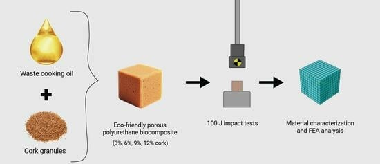
:
1. Introduction
2. Materials and Methods
2.1. Samples Composition
- 1.
- One petrochemical polyol foam without cork (PU_0) and four petrochemical polyol with different amounts of modified cork (PU_CM_3, PU_CM_6, PU_CM_9, PU_CM_12);
- 2.
- Two foams of a petrochemical polyol with varying amounts of natural cork (PU_C_3, PU_C_6);
- 3.
- One petrochemical polyol and bio-polyol (mass ratio 1:1) foam without cork (BPU_0) and petrochemical polyol and bio-polyol (mass ratio 1:1) foams with varying amounts of modified cork (BPU_CM_3, BPU_CM_6, BPU_CM_9, BPU_CM_12).
2.2. Physical Testing
2.3. Numerical Testing
3. Results and Discussion
3.1. Physical Testing Results
3.2. Numerical Results and Comparison
3.3. Specific Absorbed Energy Profile
4. Conclusions
Author Contributions
Funding
Institutional Review Board Statement
Data Availability Statement
Conflicts of Interest
References
- Verdum, M.; Jové, P. Novel Sustainable Alternatives for the Study of the Chemical Composition of Cork. Sustainability 2024, 16, 575. [Google Scholar] [CrossRef]
- Urbaniak, M.; Goluch-Goreczna, R.; Bledzki, A.K. Natural Cork Agglomerate as an Ecological Alternative in Constructional Sandwich Composites. BioResources 2017, 12, 5512–5524. [Google Scholar] [CrossRef]
- Zhang, Y.; Kacira, M. Analysis of Climate Uniformity in Indoor Plant Factory System with Computational Fluid Dynamics (CFD). Biosyst. Eng. 2022, 220, 73–86. [Google Scholar] [CrossRef]
- Pereira, H. The Thermochemical Degradation of Cork. Wood Sci. Technol. 1992, 26, 259–269. [Google Scholar] [CrossRef]
- Pereira, H. Cork: Biology, Production and Uses; Elsevier: Amsterdam, The Netherlands, 2011. [Google Scholar]
- Demertzi, M.; Paulo, J.A.; Faias, S.P.; Arroja, L.; Dias, A.C. Evaluating the Carbon Footprint of the Cork Sector with a Dynamic Approach Including Biogenic Carbon Flows. Int. J. Life Cycle Assess. 2018, 23, 1448–1459. [Google Scholar] [CrossRef]
- Demertzi, M.; Sierra-Pérez, J.; Paulo, J.A.; Arroja, L.; Dias, A.C. Environmental Performance of Expanded Cork Slab and Granules through Life Cycle Assessment. J. Clean. Prod. 2017, 145, 294–302. [Google Scholar] [CrossRef]
- Gameiro, C.P.; Cirne, J.; Gary, G.; Miranda, V.; Pinho-da-Cruz, J.; Teixeira-Dias, F. Numerical and Experimental Study of the Dynamic Behaviour of Cork. In Design and Use of Light-Weight Materials; Universidade de Aveiro: Aveiro, Portugal, 2005. [Google Scholar]
- Paulino, M.; Teixeira-Dias, F. An Energy Absorption Performance Index for Cellular Materials—Development of a Side-Impact Cork Padding. Int. J. Crashworthiness 2011, 16, 135–153. [Google Scholar] [CrossRef]
- Karliński, J.; Rusiński, E.; Smolnicki, T. Protective Structures for Construction and Mining Machine Operators. Autom. Constr. 2008, 17, 232–244. [Google Scholar] [CrossRef]
- Fernandes, F.A.O.; Pascoal, R.J.S.; Alves de Sousa, R.J. Modelling Impact Response of Agglomerated Cork. Mater. Des. 2014, 58, 499–507. [Google Scholar] [CrossRef]
- Sanchez-Saez, S.; García-Castillo, S.K.K.; Barbero, E.; Cirne, J. Dynamic Crushing Behaviour of Agglomerated Cork. Mater. Des. 2015, 65, 743–748. [Google Scholar] [CrossRef]
- Sanchez-Saez, S.; Barbero, E.; Garcia-Castillo, S.K.K.; Ivañez, I.; Cirne, J. Experimental Response of Agglomerated Cork under Multi-Impact Loads. Mater. Lett. 2015, 160, 327–330. [Google Scholar] [CrossRef]
- Sarasini, F.; Tirillò, J.; Lampani, L.; Valente, T.; Gaudenzi, P.; Scarponi, C. Dynamic Response of Green Sandwich Structures. Procedia Eng. 2016, 167, 237–244. [Google Scholar] [CrossRef]
- Boria, S.; Raponi, E.; Sarasini, F.; Tirillò, J.; Lampani, L. Green Sandwich Structures under Impact: Experimental vs Numerical Analysis. Procedia Struct. Integr. 2018, 12, 317–329. [Google Scholar] [CrossRef]
- Anjos, O.; Pereira, H.; Rosa, M.E. Tensile Properties of Cork in Axial Stress and Influence of Porosity, Density, Quality and Radial Position in the Plank. Eur. J. Wood Wood Prod. 2011, 69, 85–91. [Google Scholar] [CrossRef]
- Gil, L. New Cork-Based Materials and Applications. Materials 2015, 8, 625–637. [Google Scholar] [CrossRef] [PubMed]
- Gibson, L.J.; Easterling, K.E.; Ashby, M.F. The Structure and Mechanics of Cork. Proc. R. Soc. A Math. Phys. Eng. Sci. 1981, 377, 99–117. [Google Scholar] [CrossRef]
- Gerometta, M.; Gabrion, X.; Lagorce, A.; Thibaud, S.; Karbowiak, T. Towards Better Understanding of the Strain–Stress Curve of Cork: A Structure–Mechanical Properties Approach. Mater. Des. 2023, 235, 112376. [Google Scholar] [CrossRef]
- Crouvisier-Urion, K.; Bellat, J.-P.; Gougeon, R.D.; Karbowiak, T. Mechanical Properties of Agglomerated Cork Stoppers for Sparkling Wines: Influence of Adhesive and Cork Particle Size. Compos. Struct. 2018, 203, 789–796. [Google Scholar] [CrossRef]
- Sergi, C.; Sarasini, F.; Tirillò, J. The Compressive Behavior and Crashworthiness of Cork: A Review. Polymers 2021, 14, 134. [Google Scholar] [CrossRef]
- Urbaniak, M.; Goluch-Goreczna, R.; Bledzki, A.K.; Gajdzinski, S. Natural Cork. Part I. Cork Oak Tree Culture, Macro- and Micromorphology of Cork/Korek Naturalny Cz. I. Uprawy Debu Korkowego, Makro- i Mikroskopowa Morfologia Korka. Polimery 2017, 62, 388–394. [Google Scholar] [CrossRef]
- Fernandes, F.; Alves de Sousa, R.; Ptak, M.; Migueis, G. Helmet Design Based on the Optimization of Biocomposite Energy-Absorbing Liners under Multi-Impact Loading. Appl. Sci. 2019, 9, 735. [Google Scholar] [CrossRef]
- Sybilski, K.; Małachowski, J. Sensitivity Study on Seat Belt System Key Factors in Terms of Disabled Driver Behavior during Frontal Crash. Acta Bioeng. Biomech. 2019, 21, 169–180. [Google Scholar] [CrossRef] [PubMed]
- Barrigón Morillas, J.M.; Montes González, D.; Vílchez-Gómez, R.; Gómez Escobar, V.; Maderuelo-Sanz, R.; Rey Gozalo, G.; Atanasio Moraga, P. Virgin Natural Cork Characterization as a Sustainable Material for Use in Acoustic Solutions. Sustainability 2021, 13, 4976. [Google Scholar] [CrossRef]
- Sheikhi, M.R.; Gürgen, S.; Altuntas, O.; Sofuoğlu, M.A. Anti-Impact and Vibration-Damping Design of Cork-Based Sandwich Structures for Low-Speed Aerial Vehicles. Arch. Civ. Mech. Eng. 2023, 23, 71. [Google Scholar] [CrossRef]
- Sheikhi, M.R.; Gürgen, S.; Altuntas, O. Energy-Absorbing and Eco-Friendly Perspectives for Cork and WKSF Based Composites under Drop-Weight Impact Machine. Machines 2022, 10, 1050. [Google Scholar] [CrossRef]
- Sheikhi, M.R.; Sofuoğlu, M.A.; Chen, Z. Shear Thickening Fluid Integrated Sandwich Structures for Vibration Isolation. In Shear Thickening Fluid; Springer International Publishing: Cham, Switzerland, 2023; pp. 27–40. [Google Scholar]
- Sergi, C.; Boria, S.; Sarasini, F.; Russo, P.; Vitiello, L.; Barbero, E.; Sanchez-Saez, S.; Tirillò, J. Experimental and Finite Element Analysis of the Impact Response of Agglomerated Cork and Its Intraply Hybrid Flax/Basalt Sandwich Structures. Compos. Struct. 2021, 272, 114210. [Google Scholar] [CrossRef]
- Ptak, M.; Kaczyński, P.; Wilhelm, J.; Margarido, J.M.T.; Marques, P.A.A.P.; Pinto, S.C.; de Sousa, R.J.A.; Fernandes, F.A.O. Graphene-Enriched Agglomerated Cork Material and Its Behaviour under Quasi-Static and Dynamic Loading. Materials 2019, 12, 151. [Google Scholar] [CrossRef]
- Borowicz, M.; Isbrandt, M.; Paciorek-Sadowska, J. Effect of New Eco-Polyols Based on Pla Waste on the Basic Properties of Rigid Polyurethane and Polyurethane/Polyisocyanurate Foams. Int. J. Mol. Sci. 2021, 22, 8981. [Google Scholar] [CrossRef]
- Kurańska, M.; Banaś, J.; Polaczek, K.; Banaś, M.; Prociak, A.; Kuc, J.; Uram, K.; Lubera, T. Evaluation of Application Potential of Used Cooking Oils in the Synthesis of Polyol Compounds. J. Environ. Chem. Eng. 2019, 7, 103506. [Google Scholar] [CrossRef]
- Coman, A.E.; Peyrton, J.; Hubca, G.; Sarbu, A.; Gabor, A.R.; Nicolae, C.A.; Iordache, T.V.; Averous, L. Synthesis and Characterization of Renewable Polyurethane Foams Using Different Biobased Polyols from Olive Oil. Eur. Polym. J. 2021, 149, 110363. [Google Scholar] [CrossRef]
- Członka, S.; Kairytė, A.; Miedzińska, K.; Strąkowska, A. Polyurethane Hybrid Composites Reinforced with Lavender Residue Functionalized with Kaolinite and Hydroxyapatite. Materials 2021, 14, 415. [Google Scholar] [CrossRef]
- Strąkowska, A.; Członka, S.; Kairytė, A.; Strzelec, K. Effects of Physical and Chemical Modification of Sunflower Cake on Polyurethane Composite Foam Properties. Materials 2021, 14, 1414. [Google Scholar] [CrossRef]
- Paciorek-sadowska, J.; Borowicz, M.; Isbrandt, M. The Use of Waste from the Production of Rapeseed Oil for Obtaining of New Polyurethane Composites. Polymers 2019, 11, 1431. [Google Scholar] [CrossRef]
- Kurańska, M.; Ptak, M.; Malewska, E.; Prociak, A.; Barczewski, M.; Dymek, M.; Fernandes, F.A.O.; de Sousa, R.A.; Polaczek, K.; Studniarz, K.; et al. Cork Porous Biocomposites with Polyurethane Matrix Modified with Polyol Based on Used Cooking Oil. Materials 2023, 16, 3032. [Google Scholar] [CrossRef]


| Description | Cork Content | Nomenclature |
|---|---|---|
| Petrochemical polyol foam | - | PU_0 |
| Petrochemical polyol foam | 3% modified cork | PU_CM_3 |
| Petrochemical polyol foam | 6% modified cork | PU_CM_6 |
| Petrochemical polyol foam | 9% modified cork | PU_CM_9 |
| Petrochemical polyol foam | 12% modified cork | PU_CM_12 |
| Petrochemical polyol foam | 3% natural cork | PU_C_3 |
| Petrochemical polyol foam | 6% natural cork | PU_C_6 |
| Petrochemical polyol and bio-polyol foam | - | BPU_0 |
| Petrochemical polyol and bio-polyol foam | 3% modified cork | BPU_CM_3 |
| Petrochemical polyol and bio-polyol foam | 6% modified cork | BPU_CM_6 |
| Petrochemical polyol and bio-polyol foam | 9% modified cork | BPU_CM_9 |
| Petrochemical polyol and bio-polyol foam | 12% modified cork | BPU_CM_12 |
| [kg/m3] | |||||
|---|---|---|---|---|---|
| 90 | 0 | 3.0 | 1.1 | 0.5 | 0.1 |
| Samples | Strain Energy Density Up to 0.80 Strain Value (kJ/m3) |
|---|---|
| PU_0 | 360.36 |
| PU_CM_3 | 369.98 |
| PU_CM_6 | 293.14 |
| PU_CM_9 | 311.46 |
| PU_CM_12 | 309.68 |
| PU_C_3 | 391.69 |
| PU_C_6 | 297.33 |
| BPU_0 | 306.56 |
| BPU_CM_3 | 290.80 |
| BPU_CM_6 | 263.29 |
| BPU_CM_9 | 246.68 |
| BPU_CM_12 | 250.53 |
Disclaimer/Publisher’s Note: The statements, opinions and data contained in all publications are solely those of the individual author(s) and contributor(s) and not of MDPI and/or the editor(s). MDPI and/or the editor(s) disclaim responsibility for any injury to people or property resulting from any ideas, methods, instructions or products referred to in the content. |
© 2024 by the authors. Licensee MDPI, Basel, Switzerland. This article is an open access article distributed under the terms and conditions of the Creative Commons Attribution (CC BY) license (https://creativecommons.org/licenses/by/4.0/).
Share and Cite
Dymek, M.; Ptak, M.; Kaczyński, P.; Fernandes, F.A.O.; Alves de Sousa, R.J.; Serra, G.F.; Kurańska, M. Eco-Friendly Cork–Polyurethane Biocomposites for Enhanced Impact Performance: Experimental and Numerical Analysis. Polymers 2024, 16, 887. https://doi.org/10.3390/polym16070887
Dymek M, Ptak M, Kaczyński P, Fernandes FAO, Alves de Sousa RJ, Serra GF, Kurańska M. Eco-Friendly Cork–Polyurethane Biocomposites for Enhanced Impact Performance: Experimental and Numerical Analysis. Polymers. 2024; 16(7):887. https://doi.org/10.3390/polym16070887
Chicago/Turabian StyleDymek, Mateusz, Mariusz Ptak, Paweł Kaczyński, Fábio A. O. Fernandes, Ricardo J. Alves de Sousa, Gabriel F. Serra, and Maria Kurańska. 2024. "Eco-Friendly Cork–Polyurethane Biocomposites for Enhanced Impact Performance: Experimental and Numerical Analysis" Polymers 16, no. 7: 887. https://doi.org/10.3390/polym16070887