
Magnonic Metamaterials for Spin-Wave Control with Inhomogeneous Dzyaloshinskii–Moriya Interactions


1
School of Physics and Electronics, Henan University, Kaifeng 475004, China
2
Physical Science and Engineering Division (PSE), King Abdullah University of Science and Technology (KAUST), Thuwal 23955-6900, Saudi Arabia
3
Institute for Superconducting and Electronic Materials, Australian Institute of Innovative Materials, Innovation Campus, University of Wollongong, Squires Way, North Wollongong, NSW 2500, Australia
4
Aix Marseille University, CNRS, CINAM, 13288 Marseille, France
*
Authors to whom correspondence should be addressed.
Nanomaterials 2022, 12(7), 1159; https://doi.org/10.3390/nano12071159
Submission received: 17 February 2022
/
Revised: 21 March 2022
/
Accepted: 28 March 2022
/
Published: 31 March 2022
(This article belongs to the Special Issue Nanoscale Ferroic Materials—Ferroelectric, Piezoelectric, Magnetic, and Multiferroic Materials)
Abstract
:A magnonic metamaterial in the presence of spatially modulated Dzyaloshinskii–Moriya interaction is theoretically proposed and demonstrated by micromagnetic simulations. By analogy to the fields of photonics, we first establish magnonic Snell’s law for spin waves passing through an interface between two media with different dispersion relations due to different Dzyaloshinskii–Moriya interactions. Based on magnonic Snell’s law, we find that spin waves can experience total internal reflection. The critical angle of total internal reflection is strongly dependent on the sign and strength of Dzyaloshinskii–Moriya interaction. Furthermore, spin-wave beam fiber and spin-wave lens are designed by utilizing the artificial magnonic metamaterials with inhomogeneous Dzyaloshinskii–Moriya interactions. Our findings open up a rich field of spin waves manipulation for prospective applications in magnonics.
1. Introduction
Magnonics (or magnon spintronics) is an emerging field concentrating on the generation, detection and manipulation of magnons, the quanta of spin-wave, in ferromagnetic or antiferromagnetic metals and insulators [1,2,3,4,5,6,7,8,9]. As spin waves in magnetic insulators exhibit both low energy dissipation and long coherence length, these constitute a competitive alternative to electronic devices and are deemed to be a promising candidate as a high-quality information carrier [10,11,12,13]. Over the past decades, many properties of spin waves have been demonstrated experimentally, in analogy with electromagnetic waves: excitation and propagation [14,15,16,17,18], reflection and refraction [19,20,21,22], interference and diffraction [23,24,25] and tunneling and the Doppler effect [26,27,28].
Thus, far, based on recent progress in the fabrication of magnetic nanostructures, various device concepts have been proposed, such as spin-wave logic gates and circuits [10,29,30], waveguides [31,32], multiplexors [33], splitter [34] and diodes [35]. The implementations of those devices is usually achieved by the application of external local magnetic fields [26], spin current [28,36] and magnetic textures (for example, the chiral domain wall) [29,31,37] to control the dispersion relation of spin waves, thereby, steering the spin-wave propagation properties. Despite the soundness of the concepts, however, there are some inherent drawbacks and obstacles to applications. First, generating a local high-frequency magnetic field on micro-sized devices complicates the structure design, and the local field is often spatially inhomogeneous, which can inhibit the benefits of the device [38]. In addition, unstable magnetic textures under external excitation and at room temperature may give rise to poor reliability and high bit-error rates. Therefore, it is desirable to find a new method to manipulate the propagation of spin waves.
Recent discoveries in graded-index magnonics and magnonic metamaterials provide a new way to manipulate spin-wave propagation [39,40], which is inspired by the fields of graded-index photonics (or photonic metamaterials) [41,42,43]. The core idea of graded-index magnonics is to manipulate spin-wave propagation by designing a spatially varied magnonic refractive index. In magnetic thin films with in-plane magnetization, the spin-wave dispersion relation described by the Landau–Lifshitz–Gilbert (LLG) equation exhibits a much more complex structure compared to the isotropic dispersion relation of light. This offers extremely rich opportunities to modulate the magnonic refractive index.
Up to now, it has been shown that the graded magnonic refractive index can be created by modification of the material properties, such as non-uniform saturation magnetization or exchange constant [44,45,46,47], the magnetic anisotropy [19,20] or the internal magnetic field [37,48]. This index can be also achieved by utilizing a non-uniform external magnetic field [39,49,50,51], electric field (voltage) [52,53] or temperature [54,55]. Therefore, graded-index magnonics are expected to overcome the current limitation of magnonics and pave feasible routes for the implementation of spin-wave devices.
In this paper, we theoretically propose a magnonic metamaterial, in which we modulate the refractive index of spin waves with the inhomogeneous Dzyaloshinskii–Moriya interaction (DMI) to avoid a barely controllable local magnetic field and unstable magnetic textures. The DMI is an antisymmetric exchange interaction arising from the lack of structural inversion symmetry in magnetic films [56,57]. It has been found both for bulk materials [58,59,60] and magnetic interfaces [61].
Here, we focus on a spatial inhomogeneous interfacial DMI present in ferromagnet/heavy metal (FM/HM) bilayers realized by tuning the thickness of ferromagnetic layer or HM layer [62,63,64,65], the degree of hybridization between 3d-5d states [66] or utilizing a local gating [67]. We begin our work by rapidly deriving the spin-wave dispersion relation with spatially modulated DMI. Then, we further study spin-wave refraction and reflection at the interface between two magnetic media with different DMI and build a generalized Snell’s law of spin waves, similar to Snell’s law in optics.
According to the magnonic Snell’s law, spin-wave can also experience total internal reflection (TIR) at the DMI step interface when their incident angle is larger than a critical value (i.e., the critical angle). Moreover, magnonic Snell’s law and TIR are observed and confirmed by micromagnetic simulations. Utilizing the artificial magnonic metamaterials based on spatially modulated DMI, a spin-wave fiber owing to TIR (which can transmit spin waves over a long distance) and a spin-wave lens holding tremendous possibility to build spin-wave circuits are proposed as proofs of concept.
The paper is organized as follows. In Section 2, we introduce our theoretical model and method. Detailed results of micromagnetic simulations are presented in Section 3. Then, we discuss the realization of spin-wave fibers and lenses in Section 4. Finally, we end the paper with a summary in Section 5.
2. Analytical Model
2.1. Magnonic Snell’s Law
We consider a thin magnetic film in the plane with the thickness much smaller than lateral dimensions of the film (), whose initial magnetization is homogeneous along the direction. The magnetization dynamics are governed by the LLG Equation [68],
where is the unit direction of local magnetization with a saturation magnetization . is the phenomenological Gilbert damping constant, and is the gyromagnetic ratio. Here, is the effective field [69], and , , . A is the symmetric exchange constant, is the interfacial antisymmetric DMI constant spatially inhomogeneous along the x direction, K is the in-plane anisotropy and is the permeability of vacuum. Under the perturbative approximation, the small-amplitude spin waves propagating in the plane take the following form [70]:
where is the spin-wave contribution to magnetization (). is the spin-wave wavevector. Considering the system shown in Figure 1, we use a DMI step (i.e., in medium A and in medium B) to induce a difference in spin-wave dispersion relations between two magnetic domains. Inserting Equation (2) into Equation (1) and neglecting higher order terms, we obtain the spin-wave dispersion relation in each region [71,72],
with and . The spin-wave group velocity is , where and . To simplify the model, we assume that the group velocity is parallel to the phase velocity at each point of the dispersion relation—that is to say, the dispersion relation is isotropic.
Equation (3) represents an isofrequency circle with radius in momentum space, whose center deviates from the origin by in direction as illustrated in Figure 2a. Nevertheless, in the magnetic films with in-plane magnetization, the spin-wave dispersion relation is anisotropic at low frequencies, where dipolar contribution dominates. When increasing frequency, the isofrequency contours smoothly transform through elliptical to almost circular. Consequently, the dispersion relation is isotropic as determined by the exchange interactions at high frequencies. In the following simulations, we use quite high frequency spin waves (100 GHz), and thus the spin-wave dynamic is determined by the exchange interactions.
Based on translation symmetry considerations, the refraction angle obeys the generalized Snell’s law, which guarantees continuity of the tangential components of the vector across the DMI step interface along the axis, such that [19,20,37]. Consequently, the generalized magnonic Snell’s law based on modifying the dispersion relation with inhomogeneous DMI can be rewritten in the following form:
where is the value of . Here, the generalized Snell’s law shown in Equation (4) is derived for an interface between two spin-wave media with different material parameters (interfacial DMI), which can be viewed as graded-index magnonic metamaterials. However, this is different from Snell’s laws based on the interface inside magnetic textures, such as chiral domain walls (the interface formed by two opposite magnetic domains) [37].
2.2. Total Internal Reflection
Analogously to the case of electromagnetic waves in photonics or acoustic waves in phononics, spin waves are also expected to be completely reflected by the interface when a spin-wave travels from a medium with a higher refractive index to a medium with a lower refractive index known as TIR. TIR occurs when the incident angle , where is often called the critical angle. When , the refracted spin-wave travels along the interface between the two media or the angle of refraction is . According to the magnonic Snell’s law in Equation (4), the critical angle can be expressed as
where . Specifically, Equation (5) shows that equals when the DMI is homogenous (), i.e., all incident spin waves are fully transmitted and no reflection occurs. Furthermore, when (the difference between DMI in two regions) is chosen to be large enough, a gap falls in between the two isofrequency circles and TIR occurs at all incident angles (i.e., ). Equations (4) and (5) are the main analytical results in our paper.
3. Micromagnetic Simulations
To test the validity of these analytical findings in realistic situations, micromagnetic simulations have been proven to be an efficient tool for the investigation of spin-wave dynamics in various magnetic textures and geometries. The simulations here are performed in the GPU-accelerated micromagnetic simulations program MuMax3 [73], which solves the time-dependent LLG Equation (1) based on the finite difference method. In our simulations, we used typical magnetic parameters for YIG at zero temperature [74]: A/m, pJ/m and J/m.
All simulations presented here were performed for a thin film of size , which discretized with cuboid meshes of dimensions . The lateral dimensions of unit mesh ( and ) and the thickness of the film are all smaller than the exchange length of YIG [3]. The simulations were implemented with the mesh size nm. The simulations were split into two stages: the static and dynamic stage. In the first stage, the static stage, the magnetic configuration is stabilized by minimization of the total energy starting from the random magnetic configuration with a high value of damping ().
In the dynamic stage of the simulations, the equilibrium magnetic configuration was used to excite a spin-wave beam that propagates through the film with a small damping parameter () to ensure long-distance propagation. During this step, a Gaussian type spin-wave beam was continuously generated by a harmonic dynamic external magnetic field following a Gaussian distribution function in a small rectangular region (red double-headed arrow shown in Figure 1). The detailed description of the Gaussian spin-wave beam generation procedure can be found in Refs. [75,76,77].
The Gaussian spin-wave beam is clearly visible and does not change with time after continuously exciting a sufficiently long time, which corresponds to a steady spin-wave propagation. Moreover, to avoid spin-wave reflection at the boundaries of the film, absorbing boundary conditions are applied on all boundaries by assigning a large damping constant () near the edges.
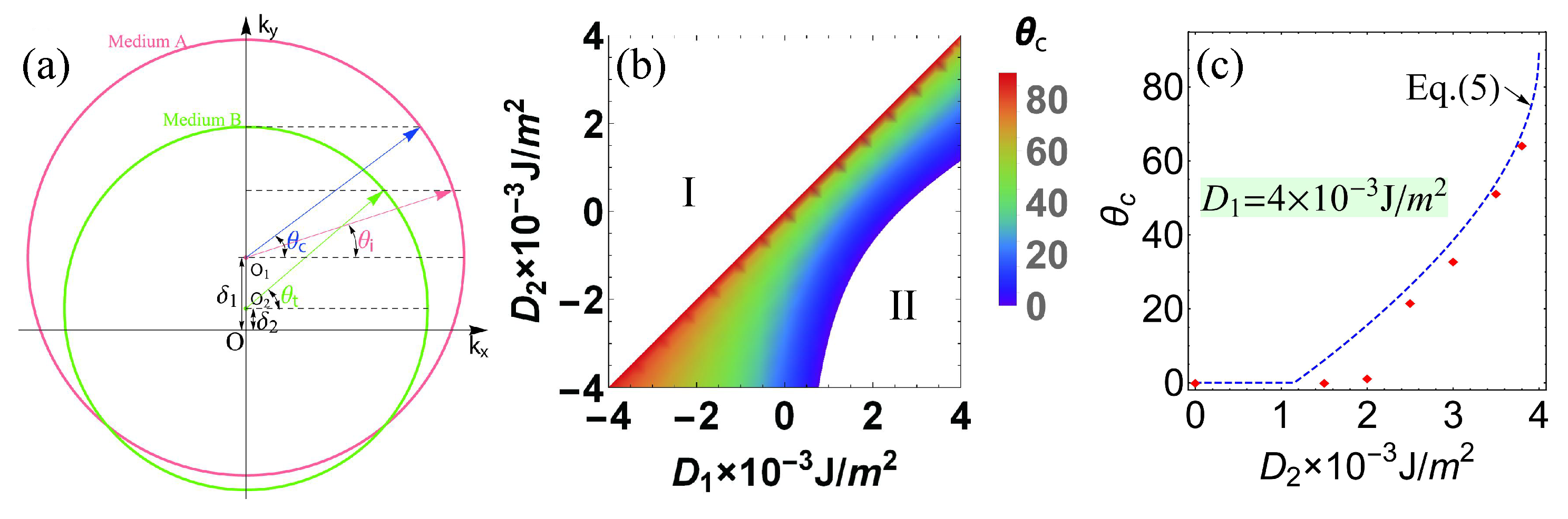
In order to verify the magnonic Snell’s law in Equation (4) for the spin-wave propagation through a DMI step interface, we focus on a 4 m × 4 m × 2 nm nanowire. The spin-wave beams presented here are all exchange-dominated spin waves with 200 nm beam width and 30 nm wavelength generated by an external AC magnetic field with frequency GHz. The phase diagram of the critical angle in the plane is shown in Figure 2b. As in the white region I, spin waves transmit from a thinner medium with a lower refractive index to a denser medium with a higher refractive index, and thus no TIR happens.
A gap falls in between the two isofrequency circles—in other words, TIR occurs in all incident angles when is chosen to be large enough as shown in the white region II. Figure 2c shows the critical angle as a function of the DMI constant in medium B, where the DMI constant of medium A is fixed at J/m. All incident angle spin waves are totally reflected at a small corresponding to Region II in Figure 2b. After that, the critical angle increases monotonically with and shows a good agreement with the analytical results.
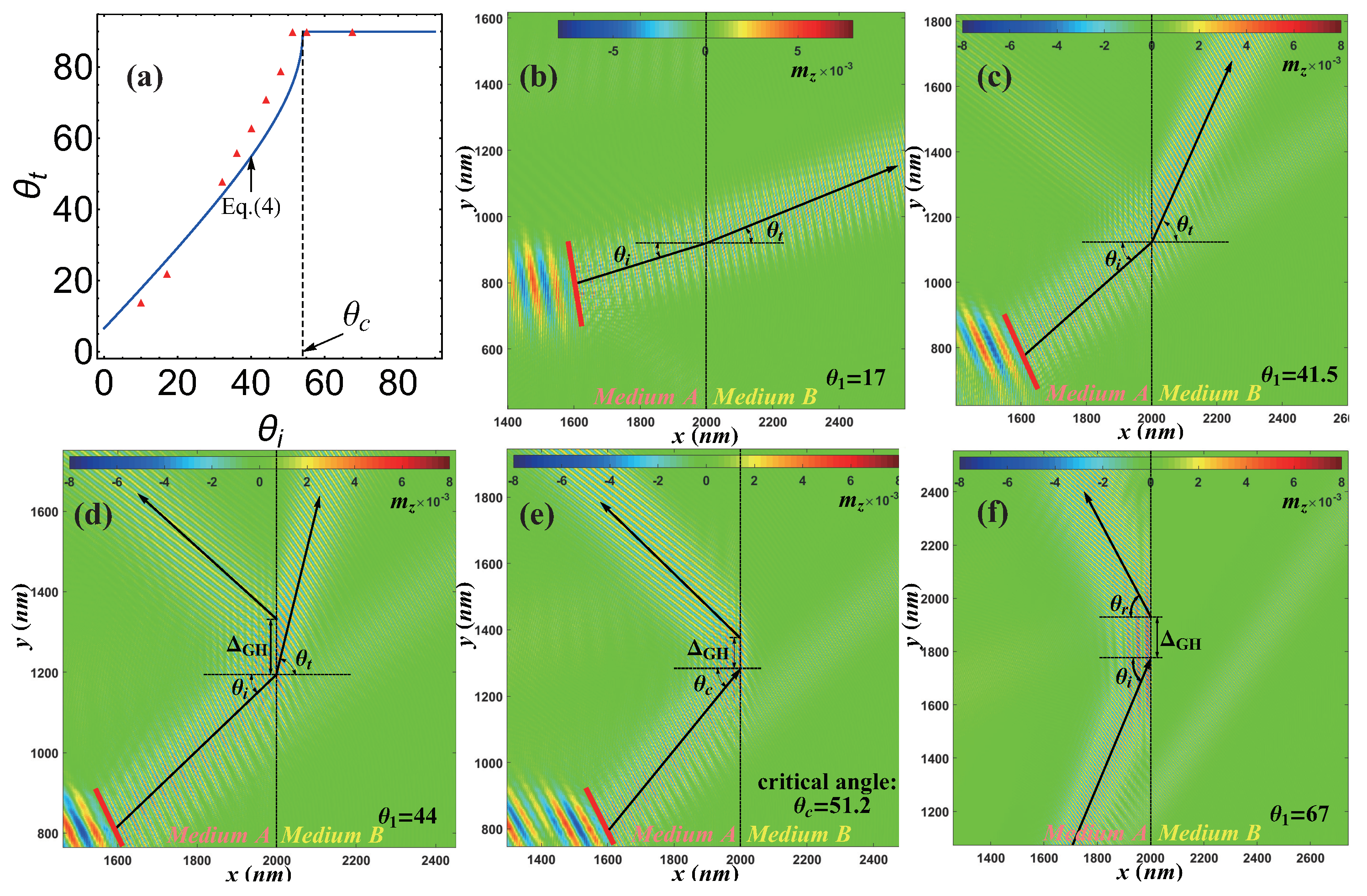
In Figure 3a, we show the refracted angle as a function of the incident angle from micromagnetic simulations (red triangle) and the prediction from Equation (4) (blue curve) with DMI constants J/m and J/m, respectively. The micromagnetic simulation for the five different incident angles, , , , and , are displayed in Figure 3b–f. Figure 3b–d correspond to the refraction mode, and Figure 3e,f are the total reflection mode. Vertical dashed lines correspond to the interface at nm between medium A (left) and medium B (right).
The critical angle observed in our simulation is estimated to be as shown in Figure 3e. It is important to comment that the spin-wave propagation direction is not strictly perpendicular to the spin-wave wavefronts in our simulation. That is to say, it is easy to observe strong anisotropy in the propagation of spin waves. Typically, for in-plane magnetized films, spin waves dynamics are anisotropic. This means that iso-frequency dispersion relation lines (IFDRLs, slices of dispersion relations for particular frequencies) are not circular. Therefore, the group velocity and phase velocities (parallel to the wave-vector) are not parallel to each other, since the group velocity direction should be normal to the IFDRLs [78].
Such an intrinsic anisotropy called spin-wave collimation effect is common in ferromagnetic films with the magnetization fixed in the plane of the film by an external magnetic field or a strong in-plane anisotropy [75,76,77]. However, in the present case, the symmetry of the spin-wave dispersion relation is broken due to the presence of DMI, and the wave vector can be shifted from the direction perpendicular to spin-wave wavefronts [70]. This anisotropy decreases with the increasing frequency of the spin-wave but it is still present at the high frequency GHz assumed in our simulations.
Moreover, a lateral shift of the spin-wave beam is observed at the interface between the reflected and the incident beams, which is called the Goos–Hnchen (GH) effect. The GH effect for spin-waves was reported in Refs. [75,76,77,78]. Furthermore, detailed investigations elucidating the role of inhomogeneous DMI on the GH shift in the reflection of the spin-wave at the interface were discussed in Ref. [22].
4. Spin-Wave Fiber and Lens
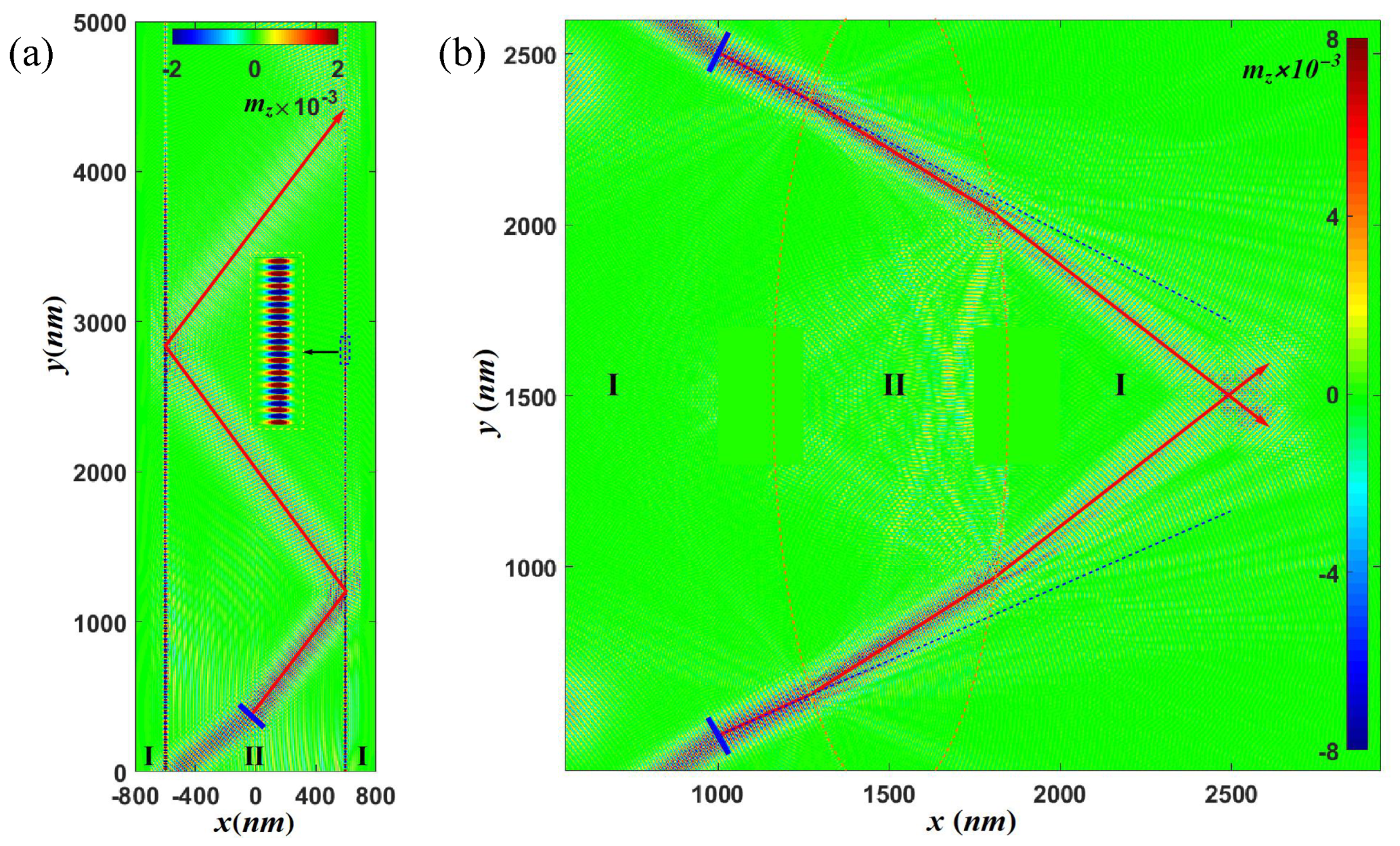
We now turn to the realization of the spin-wave fiber and spin-wave lens, which are important to manipulate spin waves in spin-wave circuitry. Two kinds of spin-wave fiber have been proposed and designed, one based on the TIR by the magnetic domain wall [37] and the other based on the TIR in the medium with a uniform external magnetic field [51]. Here, utilizing the TIR at the interface with a DMI step, we propose a new type of spin-wave fiber as shown in Figure 4a of system size 12 m × 1.6 m × 2 nm. The DMI constant in the core (region II, nm) is J/m surrounded by transparent cladding FM layers (region I, nm) with a lower index of refraction ( J/m). Two DMI steps are formed with the critical angle .
The upper one is located at nm and the lower one is located at nm. In Figure 4a, the spin-wave beam born at the middle of the nanowire (blue bar) propagates inside the core with an incident angle of greater than . This is different from the unidirectional spin-wave fiber based on domain walls [37]. The fiber here is fully bidirectional for both right/left-moving spin-wave beams when the incident angle is greater than the critical angle.
More interestingly, a bound spin-wave mode propagates a long distance inside the DMI step interface as illustrated in the inset of Figure 4a. Similar to the bound spin wave mode inside a domain wall, which acts as a local potential well for spin waves [31,79], a DMI step also creates an imaginary potential well for the bound spin wave mode [80]. The details will be discussed in our future publications.
A fundamental building block in spin-wave circuitry is a spin-wave lens that can focus or diverge spin-wave beams. Since the dispersion relation strongly depends on DMI constant, we propose a spin-wave lens by tuning the DMI distribution in the film. Figure 4b illustrates an example of a spin-wave convex lens (region I inside red dotted lines) with a DMI constant inside/outside the lens J/m, respectively. The size of the sample presented here is 6 m × 6 m × 2 nm.
Comparing the solid blue lines along the incident spin-wave beam propagation direction and the spin-wave trajectory (solid red lines with an arrow) passing through the lens, it is easy to observe focusing in the propagation of spin waves. Furthermore, a concave spin-wave lens can be obtained by reversing the DMI constants of regions I and II, which can be used to spit the spin-wave beams. Consequently, we believe that the inhomogeneous DMI can be a good playground to study spin-wave beam propagation [81].
5. Conclusions
In conclusion, we both theoretically and numerically studied spin-wave beam propagation in a two-dimensional ferromagnetic film with an inhomogeneous interfacial DMI. Utilizing a spatially varied magnonic refractive index introduced by the variation of DMI, a magnonic metamaterial or graded-index magnonic material can be realized. Snell’s law and TIR for spin waves were predicted with a DMI step interface. Moreover, we designed and studied spin-wave fibers and spin-wave lenses via micromagnetic simulations. We believe that our findings shall open up alternative directions for building reconfigurable, stabilized and scalable spin-wave circuitry in magnon introspection devices.
However, the parameters that we adopted in our simulations to investigate spin-wave propagation in the presence of spatially modulated DMI are not meant to represent a specific material but rather to explore the physical conditions under which the spin-wave total reflection occurs. From the materials standpoint, we acknowledge that the dual requirements of low damping and large DMI may seem incompatible since spin–orbit coupling originating from the adjacent heavy metal layer is detrimental to the former but central to the latter.
The excitation of short-wavelength propagating spin waves with a wavelength of 45 nm in a YIG thin film covered by CoFe nanowires was reported in a recent experiment [82], where the effective damping was only enhanced to about 10. Recent progress in materials science has proven that certain magnetic insulators do possess sizable DMIs either in their bulk [83,84,85] or at the interface [86,87,88]. Although these values remain small (typically mJ/m), these results open interesting perspectives for the achievement of large DMIs in magnetic insulators.
Author Contributions
Conceptualization, F.Z. and A.M.; methodology, F.Z.; software, F.Z.; validation, F.Z. and A.M.; formal analysis, F.Z., H.L., Z.C. and A.M.; investigation, F.Z.; resources, H.L. and A.M.; data curation, F.Z.; writing—original draft preparation, F.Z.; writing—review and editing, H.L., Z.C. and A.M.; visualization, H.L., Z.C. and A.M.; supervision, A.M.; project administration, A.M.; funding acquisition, H.L., Z.C. and A.M. All authors have read and agreed to the published version of the manuscript.
Funding
F.Z. and H.L. acknowledge the support from National Key R&D Program of China (No. 2018YFB0407600), Henan University (No. CJ3050A0240050) and National Natural Science Foundation of China (No. 11804078). F.Z. was supported by King Abdullah University of Science and Technology (KAUST). A.M. acknowledges support from the Excellence Initiative of Aix-Marseille Université—A*Midex, a French “Investissements d’Avenir” program. Z.C. acknowledges the support from Grant No. ARC (DP190100150).
Institutional Review Board Statement
Not applicable.
Informed Consent Statement
Not applicable.
Data Availability Statement
The data that support the findings of this study are available upon reasonable request from the authors.
Conflicts of Interest
The authors declare no conflict of interest.
References
- Kruglyak, V.V.; Hicken, R.J. Magnonics: Experiment to prove the concept. J. Magn. Magn. Mater. 2006, 306, 191. [Google Scholar] [CrossRef] [Green Version]
- Kruglyak, V.V.; Demokritov, S.O.; Grundler, D. Magnonics. J. Phys. D Appl. Phys. 2010, 43, 264001. [Google Scholar] [CrossRef]
- Serga, A.A.; Chumak, A.V.; Hillebrands, B. YIG magnonics. J. Phys. D Appl. Phys. 2010, 43, 264002. [Google Scholar] [CrossRef]
- Lenk, B.; Ulrichs, H.; Garbs, F.; Münzenberg, M. The Building Blocks of Magnonics. Phys. Rep. 2011, 507, 107. [Google Scholar] [CrossRef] [Green Version]
- Demokritov, S.O.; Slavin, A.N. Magnonics: From Fundamentals to Applications, 1st ed.; Springer: New York, NY, USA, 2013; p. 125. [Google Scholar]
- Chumak, A.V.; Vasyuchka, V.I.; Serga, A.A.; Hillebrands, B. Magnon spintronics. Nat. Phys. 2015, 11, 453. [Google Scholar] [CrossRef]
- Baltz, V.; Manchon, A.; Tsoi, M.; Moriyama, T.; Ono, T.; Tserkovnyak, Y. Antiferromagnetic spintronics. Rev. Mod. Phys. 2018, 90, 015005. [Google Scholar] [CrossRef] [Green Version]
- Barman, A.; Gubbiotti, G.; Ladak, S.; Adeyeye, A.O.; Krawczyk, M.; Gräfe, J.; Adelmann, C.; Cotofana, S.; Naeemi, A.; Vasyuchka, V.I.; et al. The 2021 Magnonics Roadmap. J. Phys. Condens. Matter 2021, 33, 413001. [Google Scholar] [CrossRef] [PubMed]
- Bonbien, V.; Zhuo, F.; Salimath, A.; Ly, O.; About, A.; Manchon, A. Topological aspects of antiferromagnets. J. Phys. D Appl. Phys. 2022, 55, 103002. [Google Scholar] [CrossRef]
- Khitun, A.; Bao, M.; Wang, K.L. Magnonic logic circuits. J. Phys. D Appl. Phys. 2010, 43, 264005. [Google Scholar] [CrossRef]
- Chumak, A.V.; Serga, A.A.; Hillebrands, B. Magnon transistor for all-magnon data processing. Nat. Commun. 2014, 5, 4700. [Google Scholar] [CrossRef] [Green Version]
- Zhuo, F.; Li, H.; Manchon, A. Topological phase transition and thermal Hall effect in kagome ferromagnets. Phys. Rev. B 2021, 104, 144422. [Google Scholar] [CrossRef]
- Zhuo, F.; Li, H.; Manchon, A. Topological thermal Hall effect and magnonic edge states in kagome ferromagnets with bond anisotropy. New J. Phys. 2022, 24, 023033. [Google Scholar] [CrossRef]
- Liu, Z.; Giesen, F.; Zhu, X.; Sydora, R.D.; Freeman, M.R. Spin Wave Dynamics and the Determination of Intrinsic Damping in Locally Excited Permalloy Thin Films. Phys. Rev. Lett. 2007, 98, 087201. [Google Scholar] [CrossRef] [PubMed] [Green Version]
- Serga, A.A.; Demokritov, S.O.; Hillebrands, B.; Slavin, A.N. Self-Generation of Two-Dimensional Spin-Wave Bullets. Phys. Rev. Lett. 2014, 92, 117203. [Google Scholar] [CrossRef] [PubMed]
- Covington, M.; Crawford, T.M.; Parker, G.J. Time-Resolved Measurement of Propagating Spin Waves in Ferromagnetic Thin Films. Phys. Rev. Lett. 2002, 89, 237202. [Google Scholar] [CrossRef] [PubMed]
- Demidov, V.E.; Jersch, J.; Demokritov, S.O.; Rott, K.; Krzysteczko, P.; Reiss, G. Transformation of propagating spin-wave modes in microscopic waveguides with variable width. Phys. Rev. B 2009, 79, 054417. [Google Scholar] [CrossRef]
- Demidov, V.E.; Kostylev, M.P.; Rott, K.; Münchenberger, J.; Reiss, G.; Demokritov, S.O. Excitation of short-wavelength spin waves in magnonic waveguides. Appl. Phys. Lett. 2011, 99, 082507. [Google Scholar] [CrossRef]
- Stigloher, J. Snell’s Law for Spin Waves. Phys. Rev. Lett. 2016, 117, 037204. [Google Scholar] [CrossRef]
- Kim, S.K.; Choi, S.; Lee, K.S.; Han, D.S.; Jung, D.E.; Choi, Y.S. Negative refraction of dipole-exchange spin waves through a magnetic twin interface in restricted geometry. Appl. Phys. Lett. 2008, 92, 212501. [Google Scholar] [CrossRef] [Green Version]
- Wang, Z.; Zhang, B.; Cao, Y.; Yan, P. Probing the Dzyaloshinskii–Moriya Interaction via the Propagation of Spin Waves in Ferromagnetic Thin Films. Phys. Rev. Applied 2018, 10, 054018. [Google Scholar] [CrossRef] [Green Version]
- Wang, Z.; Cao, Y.; Yan, P. Goos–Hänchen effect of spin waves at heterochiral interfaces. Phys. Rev. B 2019, 100, 064421. [Google Scholar] [CrossRef] [Green Version]
- Choi, S.K.; Lee, K.S.; Kim, S.K. Spin-wave interference. Appl. Phys. Lett. 2006, 89, 062501. [Google Scholar] [CrossRef] [Green Version]
- Perzlmaier, K.; Woltersdorf, G.; Back, C.H. Observation of the propagation and interference of spin waves in ferromagnetic thin films. Phys. Rev. B 2008, 77, 054425. [Google Scholar] [CrossRef] [Green Version]
- Birt, D.R.; Gorman, B.O.; Tsoi, M.; Li, X.; Demidov, V.E.; Demokritov, S.O. Diffraction of spin waves from a submicrometer-size defect in a microwaveguide. Appl. Phys. Lett. 2009, 95, 122510. [Google Scholar] [CrossRef]
- Demokritov, S.O.; Serga, A.A.; André, A.; Demidov, V.E.; Kostylev, M.P.; Hillebrands, B.; Slavin, A.N. Tunneling of Dipolar Spin Waves through a Region of Inhomogeneous Magnetic Field. Phys. Rev. Lett. 2004, 93, 047201. [Google Scholar] [CrossRef]
- Stancil, D.D.; Henty, B.E.; Cepni, A.G.; Van’t Hof, J.P. Observation of an inverse Doppler shift from left-handed dipolar spin waves. Phys. Rev. B 2006, 74, 060404. [Google Scholar] [CrossRef] [Green Version]
- Vlaminck, V.; Bailleul, M. Current-Induced Spin-Wave Doppler Shift. Science 2008, 322, 410. [Google Scholar] [CrossRef] [PubMed] [Green Version]
- Hertel, R.; Wulfhekel, W.; Kirschner, J. Domain-Wall Induced Phase Shifts in Spin Waves. Phys. Rev. Lett. 2004, 93, 257202. [Google Scholar] [CrossRef] [Green Version]
- Lee, K.S.; Kim, S.K. Conceptual design of spin wave logic gates based on a Mach–Zehnder-type spin wave interferometer for universal logic functions. J. Appl. Phys. 2008, 104, 053909. [Google Scholar] [CrossRef] [Green Version]
- Sanchez, F.G.; Borys, P.; Soucaille, R.; Adam, J.P.; Stamps, R.L.; Kim, J.V. Narrow Magnonic Waveguides Based on Domain Walls. Phys. Rev. Lett. 2015, 114, 247206. [Google Scholar] [CrossRef]
- Mulkers, J.; Waeyenberge, B.V.; Milošević, M.V. Effects of spatially engineered Dzyaloshinskii–Moriya interaction in ferromagnetic films. Phys. Rev. B 2017, 95, 144401. [Google Scholar] [CrossRef] [Green Version]
- Vogt, K.; Fradin, F.Y.; Pearson, J.E.; Sebastian, T.; Bader, S.D.; Hillebrands, B.; Hoffmann, A.; Schultheiss, H. Realization of a spin-wave multiplexer. Nat. Commun. 2014, 5, 3727. [Google Scholar] [CrossRef] [PubMed] [Green Version]
- Sadovnikov, A.V.; Davies, C.S.; Grishin, S.V.; Kruglyak, V.V.; Romanenko, D.V.; Sharaevskii, Y.P.; Nikitov, S.A. Magnonic beam splitter: The building block of parallel magnonic circuitry. Appl. Phys. Lett. 2015, 106, 192406. [Google Scholar] [CrossRef]
- Lan, J.; Yu, W.; Wu, R.; Xiao, J. Spin-Wave Diode. Phys. Rev. X 2015, 5, 041049. [Google Scholar] [CrossRef]
- Seo, S.M.; Lee, K.J.; Yang, H.; Ono, T. Current-Induced Control of Spin-Wave Attenuation. Phys. Rev. Lett. 2009, 102, 147202. [Google Scholar] [CrossRef] [PubMed]
- Yu, W.; Lan, J.; Wu, R.; Xiao, J. Magnetic Snell’s law and spin-wave fiber with Dzyaloshinskii–Moriya interaction. Phys. Rev. B 2016, 94, 140410. [Google Scholar] [CrossRef] [Green Version]
- Jamali, M.; Kwon, J.H.; Seo, S.M.; Lee, K.J.; Yang, H. Spin wave nonreciprocity for logic device applications. Sci. Rep. 2013, 3, 3160. [Google Scholar] [CrossRef] [PubMed]
- Davies, C.S.; Francis, A.; Sadovnikov, A.V.; Chertopalov, S.V.; Bryan, M.T.; Grishin, S.V.; Allwood, D.A.; Sharaevskii, Y.P.; Nikitov, S.A.; Kruglyak, V.V. Towards graded-index magnonics: Steering spin waves in magnonic networks. Phys. Rev. B 2015, 92, 020408. [Google Scholar] [CrossRef] [Green Version]
- Davies, C.S.; Kruglyak, V.V. Graded-index magnonics. Low Temp. Phys. 2015, 41, 760. [Google Scholar] [CrossRef] [Green Version]
- Marchand, E.W. Gradient Index Optics, 1st ed.; ScienceDirect: London, UK, 1978; p. 125. [Google Scholar]
- Chen, H.; Chan, C.T.; Sheng, P. Transformation optics and metamaterials. Nat. Mater. 2010, 9, 387. [Google Scholar] [CrossRef] [PubMed]
- Pendry, J.B.; Domínguez, A.I.F.; Luo, Y.; Zhao, R. Capturing photons with transformation optics. Nat. Phys. 2013, 9, 518. [Google Scholar] [CrossRef]
- Dadoenkova, Y.S.; Dadoenkova, N.N.; Lyubchanskii, I.L.; Sokolovskyy, M.L.; Kłos, J.W.; Romero-Vivas, J.; Krawczyk, M. Huge Goos–Hänchen effect for spin waves: A promising tool for study magnetic properties at interfaces. Appl. Phys. Lett. 2012, 101, 042404. [Google Scholar] [CrossRef]
- Xi, H.; Xue, S. Spin-wave propagation and transmission along magnetic nanowires in long wavelength regime. J. Appl. Phys. 2007, 101, 123905. [Google Scholar] [CrossRef]
- Xi, H.; Wang, X.; Zheng, Y.; Ryan, P.J. Spin wave propagation and coupling in magnonic waveguides. J. Appl. Phys. 2008, 104, 063921. [Google Scholar] [CrossRef]
- Vogel, M.; Aßmann, R.; Pirro, P.; Chumak, A.V.; Hillebrands, B.; Freymann, G.V. Control of Spin-Wave Propagation using Magnetisation Gradients. Sci. Rep. 2018, 8, 11099. [Google Scholar] [CrossRef]
- Xing, X.; Zhou, Y. Fiber optics for spin waves. NPG Asia Mater. 2016, 8, e246. [Google Scholar] [CrossRef] [Green Version]
- Perez, N.; Diaz, L.L. Magnetic field induced spin-wave energy focusing. Phys. Rev. B 2015, 92, 014408. [Google Scholar] [CrossRef] [Green Version]
- Houshang, A.; Iacocca, E.; Dürrenfeld, P.; Sani, S.; Akerman, J.; Dumas, R. Spin-wave-beam driven synchronization of nanocontact spin-torque oscillators. Nat. Nanotechnol. 2016, 11, 280. [Google Scholar] [CrossRef] [PubMed]
- Gruszecki, P.; Krawczyk, M. Spin wave beam propagation in ferromagnetic thin film with graded refractive index: Mirage effect and prospective applications. Phys. Rev. B 2018, 97, 094424. [Google Scholar]
- Wang, S.; Guan, X.; Cheng, X.; Lian, C.; Huang, T.; Miao, X. Spin-wave propagation steered by electric field modulated exchange interaction. Sci. Rep. 2016, 6, 31783. [Google Scholar] [CrossRef] [Green Version]
- Kakizakai, H.; Yamada, K.; Ando, F.; Kawaguchi, M.; Koyama, T.; Kim, S.; Moriyama, T.; Chiba, D.; Ono, T. Influence of sloped electric field on magnetic-field-induced domain wall creep in a perpendicularly magnetized Co wire. Jpn. J. Appl. Phys. 2017, 56, 050305. [Google Scholar] [CrossRef]
- Vogel, M.; Chumak, A.V.; Waller, E.H.; Langner, T.; Vasyuchka, V.I.; Hillebrands, B.; Freymann, G.V. Optically reconfigurable magnetic materials. Nat. Phys. 2015, 11, 487. [Google Scholar] [CrossRef] [Green Version]
- Busse, F.; Mansurova, M.; Lenk, B.; Ehe, M.; Münzenberg, M. A scenario for magnonic spin-wave traps. Sci. Rep. 2015, 5, 12824. [Google Scholar] [CrossRef] [PubMed] [Green Version]
- Dzyaloshinskii, I.E. A thermodynamic theory of “weak”ferromagnetism of antiferromagnetics. J. Phys. Chem. Solids 1958, 4, 241. [Google Scholar] [CrossRef]
- Moriya, T. Anisotropic Superexchange Interaction and Weak Ferromagnetism. Phys. Rev. 1960, 120, 91. [Google Scholar] [CrossRef]
- Mühlbauer, S.; Binz, B.; Jonietz, F.; Pfleiderer, C.; Rosch, A.; Neubauer, A.; Georgii, R.; Böni, P. Skyrmion Lattice in a Chiral Magnet. Science 2009, 323, 915. [Google Scholar] [CrossRef] [Green Version]
- Huang, S.X.; Chien, C.L. Extended Skyrmion Phase in Epitaxial FeGe(111) Thin Films. Phys. Rev. Lett. 2012, 108, 267201. [Google Scholar] [CrossRef] [PubMed] [Green Version]
- Zhuo, F.; Sun, Z.Z. Field-driven Domain Wall Motion in Ferromagnetic Nanowires with Bulk Dzyaloshinskii–Moriya Interaction. Sci. Rep. 2012, 6, 25122. [Google Scholar] [CrossRef] [PubMed] [Green Version]
- Fert, A.; Cros, V.; Sampaio, J. Skyrmions on the track. Nat. Nanotechnol. 2013, 8, 152. [Google Scholar] [CrossRef] [PubMed]
- Chen, G.; Zhu, J.; Quesada, A.; Li, J.; N’Diaye, A.T.; Huo, Y.; Ma, T.P.; Chen, Y.; Kwon, H.Y.; Won, C.; et al. Novel Chiral Magnetic Domain Wall Structure in Fe/Ni/Cu(001) Films. Phys. Rev. Lett. 2013, 110, 177204. [Google Scholar] [CrossRef] [PubMed] [Green Version]
- Chen, G.; Ma, T.; N’Diaye, A.T.; Kwon, H.; Won, C.; Wu, Y.; Schmid, A.K. Tailoring the chirality of magnetic domain walls by interface engineering. Nat. Commun. 2013, 4, 2671. [Google Scholar] [CrossRef] [Green Version]
- Torrejon, J.; Kim, J.; Sinha, J.; Mitani, S.; Hayashi, M.; Yamanouchi, M.; Ohno, H. Interface control of the magnetic chirality in CoFeB/MgO heterostructures with heavy-metal underlayers. Nat. Commun. 2014, 5, 4655. [Google Scholar] [CrossRef]
- Tacchi, S.; Troncoso, R.E.; Ahlberg, M.; Gubbiotti, G.; Madami, M.; Akerman, J.; Landeros, P. Interfacial Dzyaloshinskii–Moriya Interaction in Pt/CoFeB Films: Effect of the Heavy-Metal Thickness. Phys. Rev. Lett. 2017, 118, 147201. [Google Scholar] [CrossRef] [PubMed] [Green Version]
- Belabbes, A.; Bihlmayer, G.; Bechstedt, F.; Blügel, S.; Manchon, A. Hund’s Rule-Driven Dzyaloshinskii–Moriya Interaction at 3d-5d Interfaces. Phys. Rev. Lett. 2016, 117, 247202. [Google Scholar] [CrossRef] [PubMed] [Green Version]
- Nawaoka, K.; Miwa, S.; Shiota, Y.; Mizuochi, N.; Suzuki, Y. Voltage induction of interfacial Dzyaloshinskii–Moriya interaction in Au/Fe/MgO artificial multilayer. Appl. Phys. Express 2015, 8, 063004. [Google Scholar] [CrossRef]
- Gilbert, T.L. A phenomenological theory of damping in ferromagnetic materials. IEEE Trans. Magn. 2004, 40, 3443–3449. [Google Scholar] [CrossRef]
- Bogdanov, A.N.; Rößler, U.K. Chiral Symmetry Breaking in Magnetic Thin Films and Multilayers. Phys. Rev. Lett. 2001, 87, 037203. [Google Scholar] [CrossRef]
- Moon, J.H.; Seo, S.M.; Lee, K.J.; Kim, K.W.; Ryu, J.; Lee, H.W.; McMichael, R.D.; Stiles, M.D. Spin-wave propagation in the presence of interfacial Dzyaloshinskii–Moriya interaction. Phys. Rev. B 2013, 88, 184404. [Google Scholar] [CrossRef] [Green Version]
- Di, K.; Zhang, V.L.; Lim, H.S.; Ng, S.C.; Kuok, M.H.; Qiu, X.; Yang, H. Asymmetric spin-wave dispersion due to Dzyaloshinskii–Moriya interaction in an ultrathin Pt/CoFeB film. Appl. Phys. Lett. 2015, 106, 052403. [Google Scholar] [CrossRef]
- Manchon, A.; Ndiaye, P.; Moon, J.H.; Lee, H.W.; Lee, K.J. Magnon-mediated Dzyaloshinskii–Moriya torque in homogeneous ferromagnets. Phys. Rev. B 2014, 90, 224403. [Google Scholar] [CrossRef] [Green Version]
- Vansteenkiste, A.; Leliaert, J.; Dvornik, M.; Helsen, M.; Garcia-Sanchez, F.; Van Waeyenberge, B. The design and verification of MuMax3. AIP Adv. 2014, 4, 107133. [Google Scholar] [CrossRef] [Green Version]
- Klingler, S.; Chumak, A.V.; Mewes, T.; Khodadadi, B.; Mewes, C.; Dubs, C.; Surzhenko, O.; Hillebrands, B.; Conca, A. Measurements of the exchange stiffness of YIG films using broadband ferromagnetic resonance techniques. J. Phys. D Appl. Phys. 2015, 48, 015001. [Google Scholar] [CrossRef]
- Gruszecki, P.; Romero-Vivas, J.; Dadoenkova, Y.S.; Dadoenkova, N.N.; LyubchanskiiI, L.; Krawczyk, M. Goos–Hänchen effect and bending of spin wave beams in thin magnetic films. Appl. Phys. Lett. 2014, 105, 242406. [Google Scholar] [CrossRef]
- Gruszecki, P.; Dadoenkova, Y.S.; Dadoenkova, N.N.; Lyubchanskii, I.L.; Vivas, J.R.; Guslienko, K.Y.; Krawczyk, M. Influence of magnetic surface anisotropy on spin wave reflection from the edge of ferromagnetic film. Phys. Rev. B 2015, 92, 054427. [Google Scholar] [CrossRef] [Green Version]
- Gruszecki, P.; Mailyan, M.; Gorobets, O.; Krawczyk, M. Goos–Hänchen shift of a spin-wave beam transmitted through anisotropic interface between two ferromagnets. Phys. Rev. B 2017, 95, 014421. [Google Scholar] [CrossRef] [Green Version]
- Klos, J.W.; Gruszecki, P.; Serebryannikov, A.E.; Krawczyk, M. All-Angle Collimation for Spin Waves. IEEE Magn. Lett. 2015, 6, 3500804. [Google Scholar] [CrossRef] [Green Version]
- Sanchez, F.G.; Borys, P.; Vansteenkiste, A.; Kim, J.V.; Stamps, R.L. Nonreciprocal spin-wave channeling along textures driven by the Dzyaloshinskii–Moriya interaction. Phys. Rev. B 2014, 89, 224408. [Google Scholar] [CrossRef] [Green Version]
- Lee, S.J.; Moon, J.H.; Lee, H.W.; Lee, K.J. Spin-wave propagation in the presence of inhomogeneous Dzyaloshinskii–Moriya interactions. Phys. Rev. B 2017, 96, 184433. [Google Scholar] [CrossRef]
- Korner, H.S.; Stigloher, J.; Back, C.H. Excitation and tailoring of diffractive spin-wave beams in NiFe using nonuniform microwave antennas. Phys. Rev. B 2017, 96, 100401. [Google Scholar] [CrossRef] [Green Version]
- Wang, H.; Flacke, L.; Wei, W.; Liu, S.; Jia, H.; Chen, J.; Sheng, L.; Zhang, J.; Zhao, M.; Guo, C.; et al. Sub-50 nm wavelength spin waves excited by low-damping Co25Fe75 nanowires. Appl. Phys. Lett. 2021, 119, 152402. [Google Scholar] [CrossRef]
- Janson, O.; Rousochatzakis, I.; Tsirlin, A.A.; Belesi, M.; Leonov, A.A.; Rößler, U.K.; van den Brink, J.; Rosner, H. The quantum nature of skyrmions and half-skyrmions in Cu2OSeO3. Nat. Commun. 2014, 5, 5376. [Google Scholar] [CrossRef] [PubMed] [Green Version]
- Qian, F.; Bannenberg, L.; Wilhelm, H.; Chaboussant, G.; Debeer-Schmitt, L.M.; Schmidt, M.P.; Aqeel, A.; Palstra, T.T.M.; Brück, E.; Lefering, A.J.E.; et al. New magnetic phase of the chiral skyrmion material Cu2OSeO3. Sci. Adv. 2018, 4, eaat7323. [Google Scholar] [CrossRef] [PubMed] [Green Version]
- Deng, L.; Wu, H.C.; Litvinchuka, A.P.; Yuan, N.F.Q.; Lee, J.-J.; Dahal, R.; Berger, H.; Yang, H.-D.; Chu, C.-W. Room-temperature skyrmion phase in bulk Cu2OSeO3 under high pressures. Proc. Natl. Acad. Sci. USA 2020, 117, 8783–8787. [Google Scholar] [CrossRef] [PubMed] [Green Version]
- Avci, C.O.; Rosenberg, E.; Caretta, L.; Büttner, F.; Mann, M.; Marcus, C.; Bono, D.; Ross, C.A.; Beach, G.S.D. Interface-driven chiral magnetism and current-driven domain walls in insulating magnetic garnets. Nat. Nanotechnol. 2019, 14, 561–566. [Google Scholar] [CrossRef] [PubMed]
- Caretta, L.; Rosenberg, E.; Büttner, F.; Fakhrul, T.; Gargiani, P.; Valvidares, M.; Chen, Z.; Reddy, P.; Muller, D.A.; Ross, C.A.; et al. Interfacial Dzyaloshinskii–Moriya interaction arising from rare-earth orbital magnetism in insulating magnetic oxides. Nat. Commun. 2020, 11, 1090. [Google Scholar] [CrossRef] [PubMed]
- Ding, S.; Baldrati, L.; Ross, A.; Ren, Z.; Wu, R.; Becker, S.; Yang, J.; Jakob, G.; Brataas, A.; Kläui, M. Identifying the origin of the nonmonotonic thickness dependence of spin–orbit torque and interfacial Dzyaloshinskii–Moriya interaction in a ferrimagnetic insulator heterostructure. Phys. Rev. B 2020, 102, 054425. [Google Scholar] [CrossRef]
Figure 1.
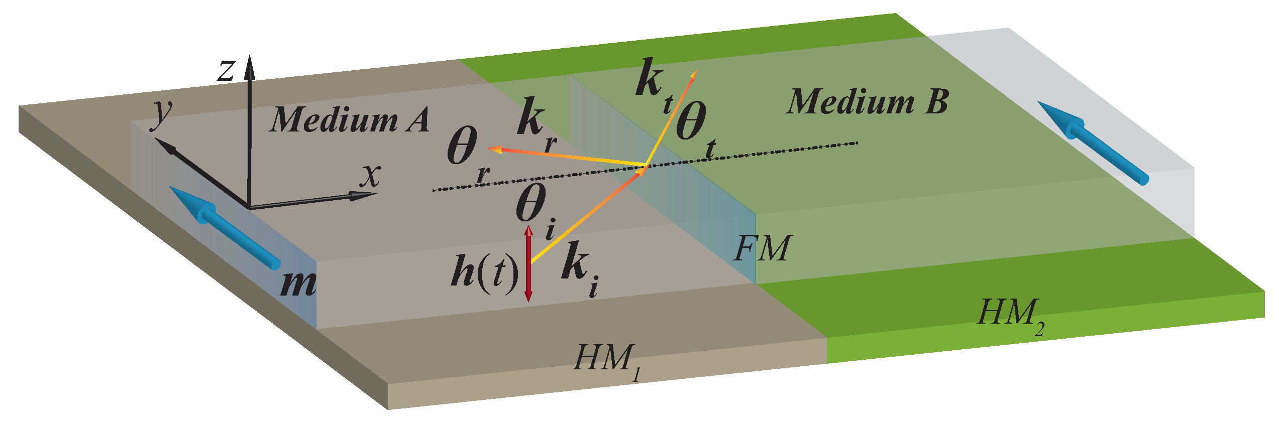
Schematic illustration of spin-wave transmission and reflection at an interface between media A and B with different interfacial DMI in a thin YIG film. The interfacial DMI step here is realized by utilizing two different HM layers (HM and HM) below the YIG film. The blue arrows along the direction denote the magnetization . , and are the wave vectors of the incident, refracted and reflected spin-wave shown as the yellow and red arrows, respectively. denote their angles with respect to the interface normal. The red double-headed arrow shows the Gaussian distribution AC Magnetic field exciting the spin-wave.
Figure 1.
Schematic illustration of spin-wave transmission and reflection at an interface between media A and B with different interfacial DMI in a thin YIG film. The interfacial DMI step here is realized by utilizing two different HM layers (HM and HM) below the YIG film. The blue arrows along the direction denote the magnetization . , and are the wave vectors of the incident, refracted and reflected spin-wave shown as the yellow and red arrows, respectively. denote their angles with respect to the interface normal. The red double-headed arrow shows the Gaussian distribution AC Magnetic field exciting the spin-wave.

Figure 2.
(a) Schematic illustrations of reflection and refraction of spin-wave at an interface between two different media in wave vector () space. The pink and green circles indicate the individual frequency contours of the allowed modes in the same-color-coded media A and B, respectively. The color-coded arrows denote the spin-wave vectors propagating in each medium, as indicated by the incident (pink) and refracted (green) rays. The blue arrow denotes the critical angle. (b) Phase diagrams of critical angle in the plane. No TIR exists in the white regions. (c) Critical angle as a function of DMI constants with a fixed DMI constant J/m. The symbols (red squares) are simulation data, and the solid curve represents the analytical results of Equation (5).

Figure 3.
(a) The refracted angle as a function of the incident angle. Vertical dashed and solid lines correspond to the critical angle . (b–f) The micromagnetic simulations results for spin-wave beam reflection and refraction under different incident angles (b) , (c) , (d) , (e) and (f) . The DMI constants in medium A and B are J/m and J/m, respectively. The color map shows the z component of the magnetization in the snapshot of micromagnetic simulations at some selected time. The black solid lines correspond to the rays of the incident and refractive beams. The red rectangular area is the excitation area of the spin-wave, and the exciting field frequency is GHz.

Figure 4.
(a) Schematic illustration of a spin-wave fiber. The inset shows the enlarged figure at the interface. (b) Schematic illustration of a spin-wave convex lens. In all of the above figures, the color map shows z component of the magnetization in the snapshot of micromagnetic simulations at some selected time. The spin-wave trajectories are represented by solid red lines with an arrow. The simulated propagation of the spin wave excited by a AC source in blue bars with an exciting frequency GHz.

Publisher’s Note: MDPI stays neutral with regard to jurisdictional claims in published maps and institutional affiliations. |
© 2022 by the authors. Licensee MDPI, Basel, Switzerland. This article is an open access article distributed under the terms and conditions of the Creative Commons Attribution (CC BY) license (https://creativecommons.org/licenses/by/4.0/).
Share and Cite
MDPI and ACS Style
Zhuo, F.; Li, H.; Cheng, Z.; Manchon, A. Magnonic Metamaterials for Spin-Wave Control with Inhomogeneous Dzyaloshinskii–Moriya Interactions. Nanomaterials 2022, 12, 1159. https://doi.org/10.3390/nano12071159
AMA Style
Zhuo F, Li H, Cheng Z, Manchon A. Magnonic Metamaterials for Spin-Wave Control with Inhomogeneous Dzyaloshinskii–Moriya Interactions. Nanomaterials. 2022; 12(7):1159. https://doi.org/10.3390/nano12071159
Chicago/Turabian StyleZhuo, Fengjun, Hang Li, Zhenxiang Cheng, and Aurélien Manchon. 2022. "Magnonic Metamaterials for Spin-Wave Control with Inhomogeneous Dzyaloshinskii–Moriya Interactions" Nanomaterials 12, no. 7: 1159. https://doi.org/10.3390/nano12071159
Note that from the first issue of 2016, this journal uses article numbers instead of page numbers. See further details here.