1. Introduction
In the recent past, we have worked on biomimetic hair-flow-sensors. Apart from sensor design and fabrication processes, we have investigated possibilities to adaptively use electromechanical schemes to improve sensor performance. Using models for energy buffering two-port transducers we have identified the possibilities to change the mechanical response of the hair-sensors by applying (1) a DC voltage or (2) an AC voltage frequency matched to the flow signal or (3) an AC non frequency-matched voltage at the electrical side of the transducer. Each of the schemes mediates changes in the effective rotational spring-stiffness of the system, which, depending on frequency and sometimes the phase, leads to parametric interaction with the flow-signal present at the mechanical port of the system. Despite the fact that we show the benefits of such schemes for our flow-sensors only, the two-port models used are far more generic and suggest suitability of these schemes in a much broader range of applications. With this in mind we have put the results of these three schemes in this one overview but do not claim new results relatively to earlier reported studies, notably references [
1,
2,
3].
Our flow-sensors are hair based and are inspired by crickets, which use filiform hairs, mounted on their cerci (
Figure 1), to extract aerodynamic information from their environment, to e.g., escape from attacks of predators like spiders. These hairs turn out to be perceptive to low-frequency air flows [
4], with amplitudes down to 30 μm/s [
5] and operate down to energy levels around the thermal-mechanical noise of the hairs [
6].
Figure 1.
(a) Photograph of the Acheta Domesticus. (b) SEM image of the base part of a cercus. (c) SEM image close-up of a filiform flow-sensitive hair. (Image courtesy of J. Casas, Université de Tours).
Figure 1.
(a) Photograph of the Acheta Domesticus. (b) SEM image of the base part of a cercus. (c) SEM image close-up of a filiform flow-sensitive hair. (Image courtesy of J. Casas, Université de Tours).
Several research groups have worked on the development of artificial hair-flow sensors. Sensing of DC-flows using hair-inspired flow sensors was shown by Ozaki
et al. [
7]. They fabricated artificial hairs using cantilevers with read-out by strain gauges, and demonstrated the measurement of flow velocities up to 2 m/s. Other groups also developed cantilever-based structures with strain gauges for measurement of DC-flows [
8], and showed measurements of flow velocities up to 20 m/s [
9] and 45 m/s [
10]. Sadeghi
et al. [
11] developed artificial hair flow sensor by manually mounting a hair on a hydraulic sensor system, for conversion of angular rotation into capacitive changes, capable of measuring DC-flows up to 10 m/s.
In contrast, hair-inspired flow sensors for measurement of (tiny) AC-flows have been designed and fabricated in our group [
12]. Improvement of fabrication methodologies has led to better performance (
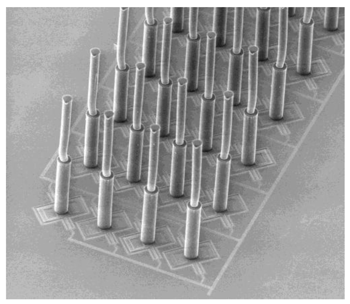
Figure 2), making it possible to detect and measure flow velocities in the range of sub-mm/s while retaining a bandwidth on the order of 1 kHz [
13]. Furthermore, we have demonstrated the use of arrays of hair-sensors [
14] and shown their potential for the ultimate development of a flow camera inspired by the cerci of crickets [
15].
Figure 2.
SEM image of a MEMS hair flow sensor array (hair length: 900 μm).
Figure 2.
SEM image of a MEMS hair flow sensor array (hair length: 900 μm).
Here, we report the use of voltage control to tune the sensor response of our flow sensors. By applying a voltage to the sensor’s capacitive structures, one obtains Electrostatic Spring Softening (ESS), which can be used to e.g., increase sensitivity and enhance the mechanical response of these sensors [
16]. The possibility to use ESS in combination with electrostatic actuation was shown in [
17]. In this paper, we focus on driving our flow sensors by airflow rather than actuating them electrostatically. Specifically we give an overview of how ESS by voltage control can be used to adaptively change the mechanical transfer function of the system, tune the sensor response towards specific frequencies and achieve selective gain, and perform electromechanical frequency up-conversion of low-frequency air flows.
2. Theory and modeling
The motion of a flow susceptible hair is described by a second order mechanical system, wherein a harmonic air-flow causes the hair to periodically rotate due to a drag torque
T(
t) caused by viscous forces [
2]. The system’s response is governed by its moment of inertia
J, torsional resistance
R and torsional stiffness
S:
Figure 3.
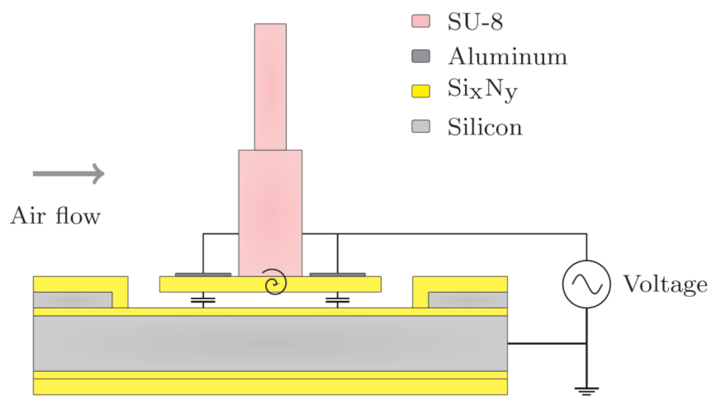
Stiffness control by applying bias voltages to the sensor’s capacitances.
Figure 3.
Stiffness control by applying bias voltages to the sensor’s capacitances.
In our MEMS hair-flow sensory system, which is fabricated as described by Bruinink
et al. [
13], the torsional stiffness
S is controlled using a bias voltage on the sensor membrane electrodes (
Figure 3). By symmetrically supplying voltages to the electrodes of the sensor, the electrostatic transduction nature of the system is exploited to obtain ESS, without actually mechanically driving the sensor. To model the system’s behavior under the application of symmetric bias voltages, we consider the electrostatically induced torque and stiffness, which can be calculated from the first and second derivative of the energy in the capacitor with respect to
θ respectively.
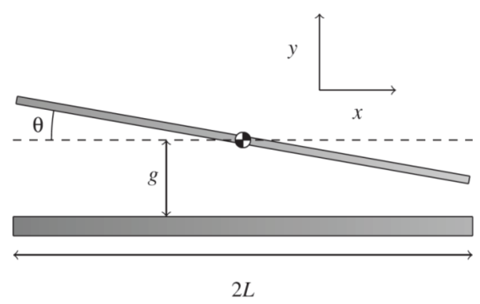
Figure 4.
Geometry of the angle-dependent rectangular capacitor.
Figure 4.
Geometry of the angle-dependent rectangular capacitor.
Due to the small angles
θ encountered in practice and since the gap is much smaller than both the width w and length of the plates 2
L, the capacitor can be treated as parallel plate geometry (
Figure 4). The sensor operates in air, for which the relative electric permittivity is assumed to be equal to 1. Additionally, the two silicon-nitride layers with thicknesses
t1 and
t2, and relative permittivity
εr increase the gap-distance, leading to an effective gap
geff:
The angle dependent capacitance
C(
θ) for the rotational sensor using the parallel plate approximation is given by:
Transduction principles are used to find the electrostatic spring softening by an angle-dependent and voltage-controlled capacitor. For this, we use Legendre’s transform for the co-energy
E’ of the system, since the capacitor is so-called voltage-controlled:
Where
S0 is the intrinsic material-based stiffness. The effective stiffness is found by differentiating twice with respect to the rotational angle
θ at constant voltage
u:
Hence, on applying a bias voltage
u, the total torsional stiffness
S becomes:
These expressions state that the total torsional stiffness
S contains both the intrinsic material-based stiffness
S0 and a voltage-dependent stiffness, allowing for electrostatic control of the system’s mechanical response. For calculating the theoretical response, the geometrical and other properties of the capacitive structure, and parameters of the hair flow sensory system are listed in
Table 1.
Table 1.
Parameter values of the hair mechanical system and the capacitor.
Table 1.
Parameter values of the hair mechanical system and the capacitor.
| Description | Symbol | Value | Unit |
| Torsional stiffness | S0 | 9.5 × 10⁻⁹ | N·m/rad |
| Moment of inertia | J | 3.1 × 10⁻¹⁶ | kg·m2 |
| Membrane length | L | 95 | μm |
| Membrane width | w | 90 | μm |
| Gap distance | g | 850 | nm |
| Nitride thickness | t1 | 1000 | nm |
| Nitride thickness | t2 | 200 | nm |
| Relative permittivity | εr | 7.5 | |
3. Results and Discussion
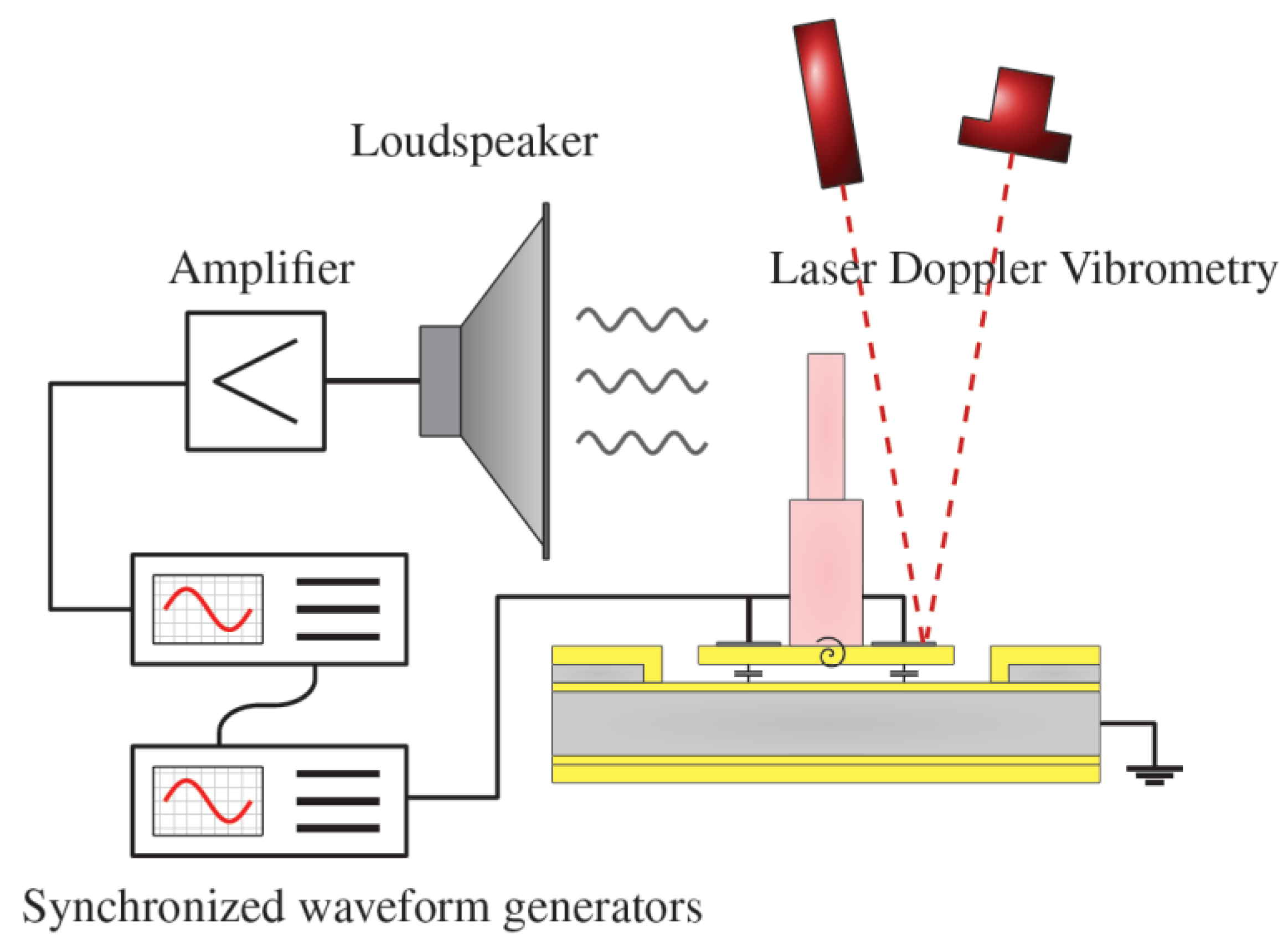
ESS-experiments using laser-vibrometry to measure the sensor’s response are performed using the experimental setup shown in
Figure 5. A waveform generator (Agilent 33220A-001) is used to generate a sinusoidal signal at a frequency
fa that is supplied to an amplifier. This amplifier drives a loudspeaker (Visaton WS 17 E) to generate the oscillating airflow. Another voltage source is used to supply the bias voltage to the top electrodes. The bottom electrode is grounded, as is the measurement setup. The sensor rotational angle
θ is derived from Laser Doppler Vibrometry using a Polytec MSA-400. Although the SEM-picture in
Figure 2 depicts an array of hair flow sensors, during the experiments described in this work just one hair flow sensor was measured at a time.
Figure 5.
Measurement setup for determining the membrane displacement of the hair flow sensor.
Figure 5.
Measurement setup for determining the membrane displacement of the hair flow sensor.
3.1. DC-Biasing
In one experiment [
15], a DC-bias voltage was used to control the system’s torsional stiffness. Following our analysis, the torsional stiffness
S is frequency-independently reduced by the applied DC-bias voltage
Udc.
For frequencies below the sensor’s resonance frequency, the system will show a larger sensitivity due to its lower torsional stiffness. In addition, also the resonance frequency
ωr of the system is affected:
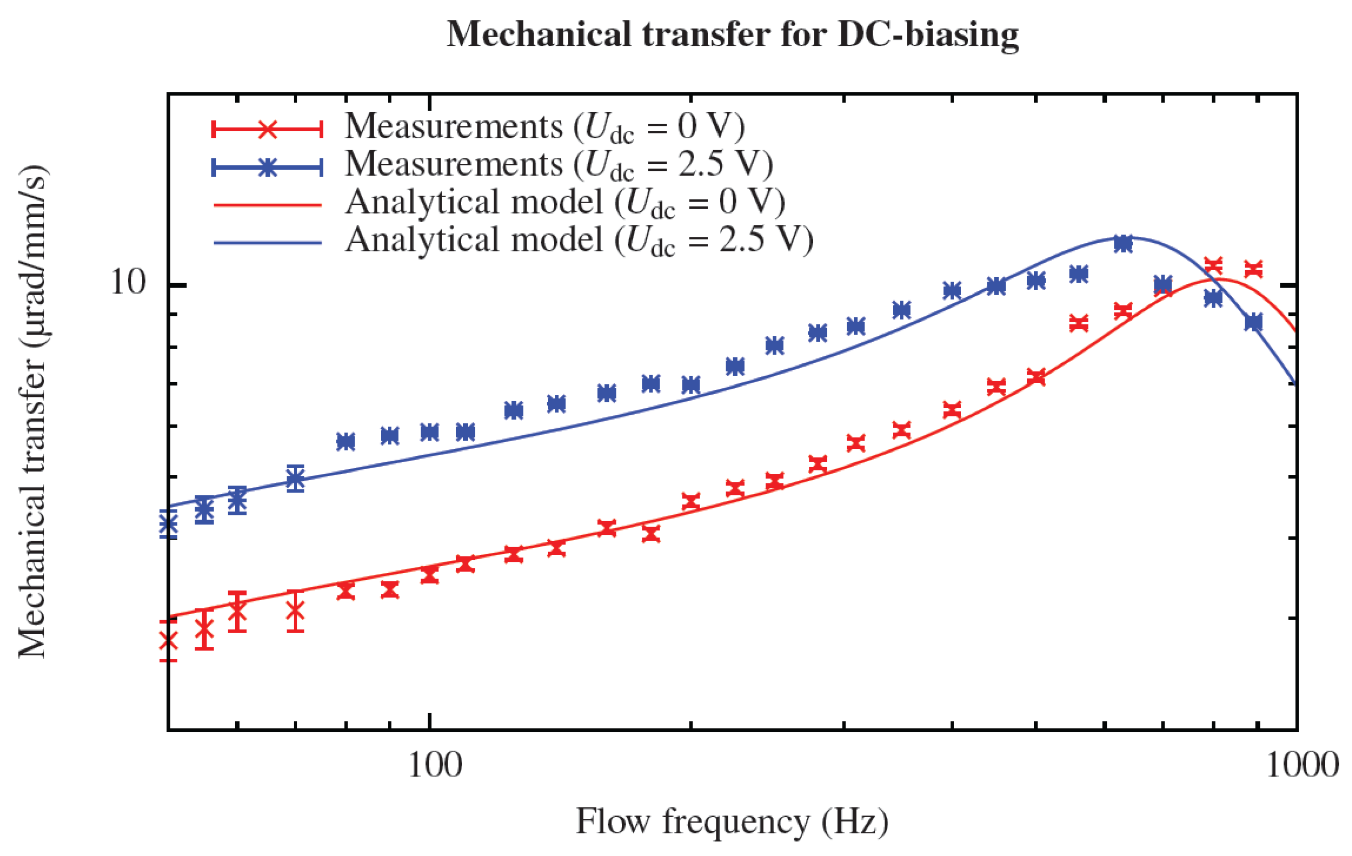
To verify the increase in sensitivity and reduction in bandwidth, the mechanical transfer was experimentally determined for flow frequencies from 100 to 1000 Hz with and without the application of a 2.5 V DC-bias voltage. This resulted in an increase in sensitivity of about 80% for frequencies within the sensor’s bandwidth. In addition, the resonance frequency
ωr is observed to decrease (about 20%). Overall, measurements are in good agreement with modeling and it is shown clearly that DC-biasing leads to a larger sensitivity below the sensor’s resonance frequency (
Figure 6) [
1].
Figure 6.
Enhancing the mechanical transfer of the hair flow sensor by applying a DC-bias voltage.
Figure 6.
Enhancing the mechanical transfer of the hair flow sensor by applying a DC-bias voltage.
3.2. Parametric Amplification
In a second set of experiments [
2], we investigated improvement of the performance of the sensors as well as the possibility to achieve adaptive filtering, using non-resonant parametric amplification (PA). Parametric amplification is a mechanism based on modulation of one or more system parameters, in order to control the system behavior. This leads to complex interactions between the modulating signals in which amplitude, frequency and phase play important roles [
18,
19]. In this work, we obtain the conditions for PA by changing the DC-bias voltage to an AC-bias voltage (also called pump signal), which is another way of exploiting ESS. As a result, the torsional stiffness will exhibit a time-dependence:
in which
Up is the pump amplitude,
φp the pump phase and
ωp the pump frequency. Parametric amplification can give selective gain or attenuation, depending on the pump frequency
fp (
ωp = 2
πfp) and pump phase
φp. Equal frequencies for flow and pump (
fp =
fa) provides coherence in torque and spring softening, for which the pump phase determines whether the system will show relative amplification or attenuation. Therefore, it is possible to realize a very sharp band pass/stop filter, depending on the pump settings.
Setting the frequency of the AC-bias voltage to 150 Hz, its amplitude to 5 V and the pump phase to the value producing maximum gain, and supplying an oscillating air flow consisting of three frequency components (135 Hz, 150 Hz and 165 Hz), filtering and selective gain of the flow signal are demonstrated (
Figure 7). The presence of a bias-signal, through the action of non-resonant PA, increases the frequency-matched signal by 20 dB, whereas the other two components are only amplified by 8–9 dB, resulting in selective gain of the flow signal [
2].
Figure 7.
Measured gain of about 20 dB for the flow frequency component at 150 Hz determined by FFT. The AC-bias voltage is fixed at fp = 150 Hz with an amplitude of 5 V.
Figure 7.
Measured gain of about 20 dB for the flow frequency component at 150 Hz determined by FFT. The AC-bias voltage is fixed at fp = 150 Hz with an amplitude of 5 V.
3.3. EMAM
In a third series of experiments [
3], we implemented ESS by setting the AC-bias voltage frequency considerably higher than the frequency of the air-flow (
fp ≫
fa). As a result, the system’s torsional stiffness is electromechanically modulated, which results in Electro Mechanical Amplitude Modulation (EMAM),
i.e., the low-frequency flow will be up-converted to frequencies 2
ωp ±
ωα.
To perform EMAM-experiments, the vibrometer output voltage representing the hair’s angular velocity (
Figure 5) was fed to an adjustable band pass filter (Stanford SR 650). The filtered output was supplied to a Lock-In Amplifier (Stanford SR 830) with its reference frequency set to twice the pump frequency, for demodulation of the modulated membrane velocity by synchronous detection.
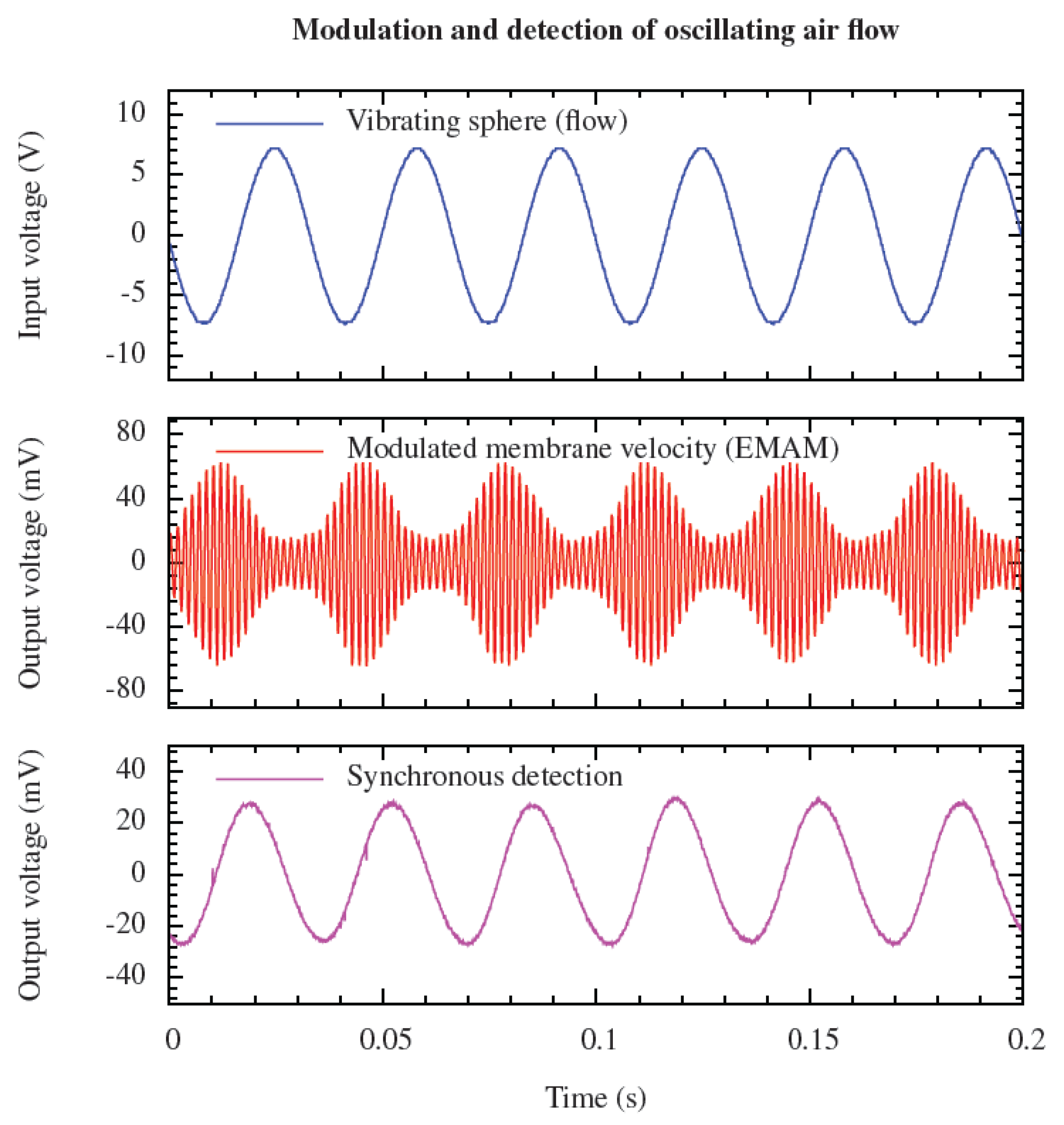
Figure 8 shows the measured (modulated) membrane velocity, together with the applied voltage to the vibrating sphere (30 Hz) and the resulting signal after synchronous detection (at 600 Hz) using the Lock-In Amplifier.
Figure 8.
The applied periodic air-flow (30 Hz), the amplitude modulated membrane velocity and the synchronous detected flow signal (30 Hz) in the time-domain. The AC-bias voltage was set to 300 Hz with amplitude of 3 V.
Figure 8.
The applied periodic air-flow (30 Hz), the amplitude modulated membrane velocity and the synchronous detected flow signal (30 Hz) in the time-domain. The AC-bias voltage was set to 300 Hz with amplitude of 3 V.
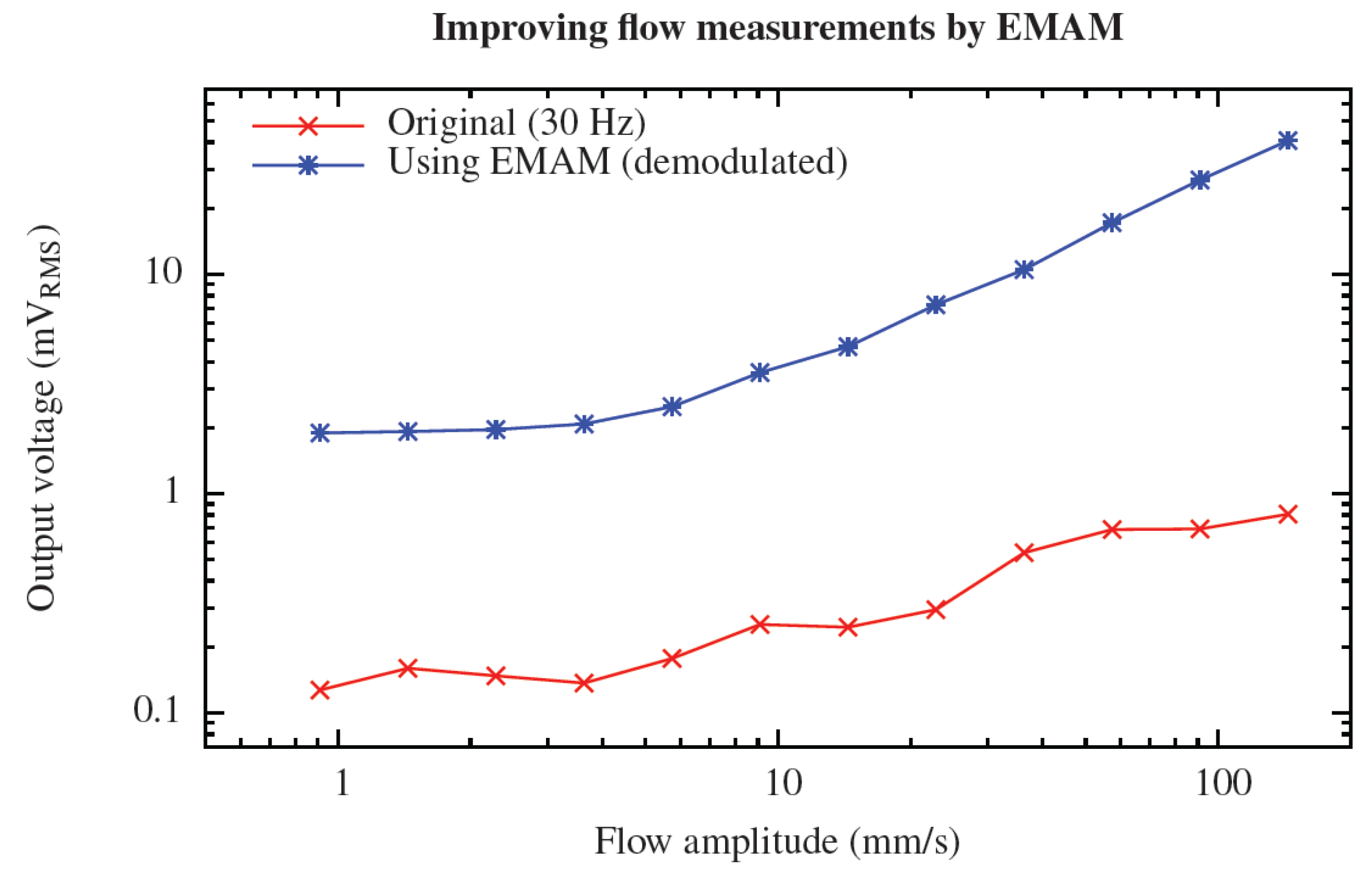
The quality of the measurements at lower frequencies is significantly improved using EMAM (
Figure 9). The output RMS voltage of the vibrometer signal was measured for varying flow velocities, still at a frequency of 30 Hz, both for the original flow signal (band-pass filter is set to 25–35 Hz) and the demodulated EMAM signal (bandpass filter is set to 565–635 Hz). The AC-bias voltage settings were not changed. Without EMAM, a noisy relationship between the flow amplitude and the resulting output voltage is observed, as well as large, undesired, variations with frequency. However, with EMAM, a clear linear relationship is observed for flow velocity amplitudes above 5 mm/s, showing that the measurement quality of low frequency flows too can be improved by ESS [
3].
Figure 9.
Improvement of the quality of the measured RMS-voltage values at low frequency signals using EMAM. In case of EMAM, a clear linear relationship between flow and output voltage is observed above the system’s noise level (>5 mm/s).
Figure 9.
Improvement of the quality of the measured RMS-voltage values at low frequency signals using EMAM. In case of EMAM, a clear linear relationship between flow and output voltage is observed above the system’s noise level (>5 mm/s).
4. Discussion
The three discussed schemes of electrostatic spring softening have their specific implications on sensing performance, giving each of these ESS-types advantages and drawbacks. Therefore, depending on the application of a sensory system, one specific scheme of ESS may be favored over other implementations of ESS.
Theory and experiments for applying a DC-bias voltage to our flow sensory system clearly showed an increase in sensitivity for a wide band of frequencies, at the cost of a (slight) reduction in resonance frequency. This method can be interesting when little is known about the frequencies of the flow of interest and a wide band measurement is required. However, although theoretically high gain of the flow signal is possible, a trade-off exists with respect to instability by pull-in. Therefore, the achieved gain by DC-biasing is practically limited to about a factor of 2–3.
By replacing the DC-bias voltage with an AC-bias voltage and matching frequencies of flow and voltage high gain values can be achieved while retaining the sensor’s bandwidth. Although these high gain factors are tunable by choosing a judicious voltage, information on frequency and phase of the surrounding air flow is required in order to realize matching of frequencies and finding the optimal phase for achieving optimal amplification of the flow signal. Hence, this method allows for measurement of flow signals from which one has knowledge a priori. This can, for example, be the case when observing modulated flows (e.g., for acoustic communication purposes or dealing with rotary machines).
Setting the frequency of the AC-bias voltage much higher than the frequency of the incoming air flow, electromechanical amplitude modulation of the air flow is achieved. This parametric-based modulation technique offers clear benefits in case of sensory systems suffering from instrumentation noise, by up converting the flow-related information to higher frequencies and increasing the signal-to-noise ratio. More general, the origin of the instrumental noise spectrum indicates whether EMAM can indeed help to improve detection of low-frequency air flows. Further, the application of EMAM is not limited to sinusoidal air flows, but is also appropriate for usage on more complicated air flow signals, like transient flows. A limitation of EMAM is that this method is only applicable in case flow frequencies are well below the system’s resonance in order to keep the upconversion frequencies within the sensor’s bandwidth. That is, the system’s net bandwidth will be limited by about a factor 10–20 for achieving a clear AM-representation of the air flow.
More general, implementing ESS for enhancing the sensor’s performance is not only applicable to our biomimetic hair flow sensory system, but is applicable to other energy-buffering two-port transducers as well. Since the used theory is based entirely on the nature of energy buffering transducers, equivalents of stiffness control for e.g., increasing sensitivity can also be realized for piezo-electric, electromagnetic and other types of energy buffering transducers.
5. Conclusions
We have provided an overview of our experiments on electromechanical, adaptive changes of biomimetic capacitive flow-sensors, using electrostatic spring softening. Since our hair-sensors are representative of a class of energy-buffering two-port transducers, we have argued that the investigated schemes are more widely applicable. The schemes discussed were the application of a DC-bias voltage mediating up to 80% improvement of the mechanical responsivity at flow signal-frequencies below the sensor’s resonance. The application of an AC-bias voltage allowing for tunable filtering and frequency and phase selective gain of up to 20 dB. Finally we discussed how quality and fidelity of low frequency flow measurements can be improved using higher frequency modulating AC-bias voltages, resulting in a flow detection limit down to 5 mm/s at 30 Hz flow frequency.


