A Resonant Pressure Sensor Based upon Electrostatically Comb Driven and Piezoresistively Sensed Lateral Resonators


 , and
, and 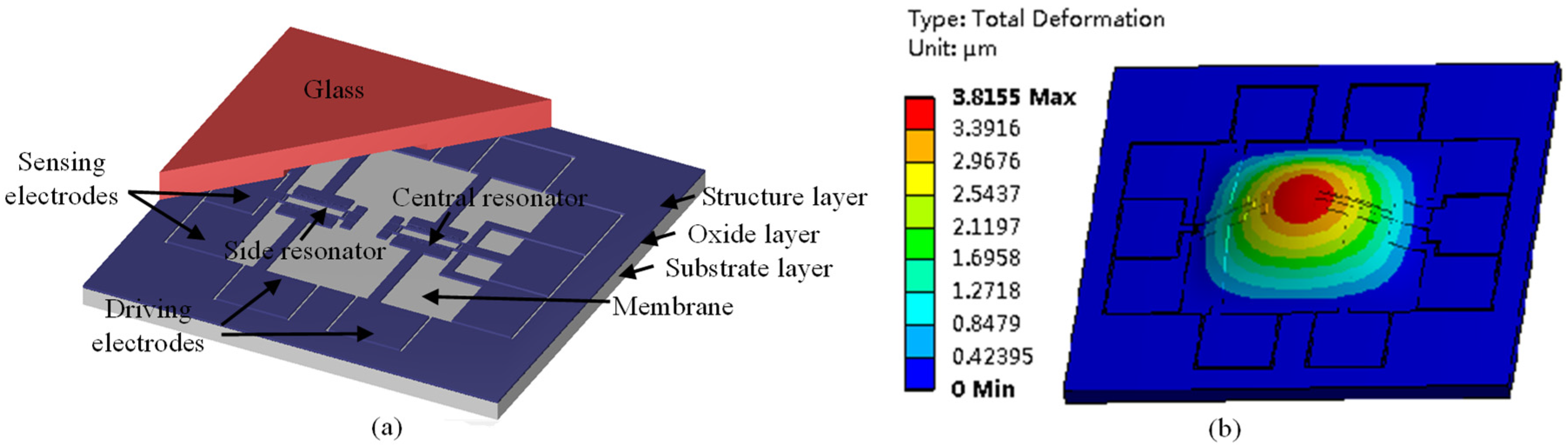
Abstract
:1. Introduction
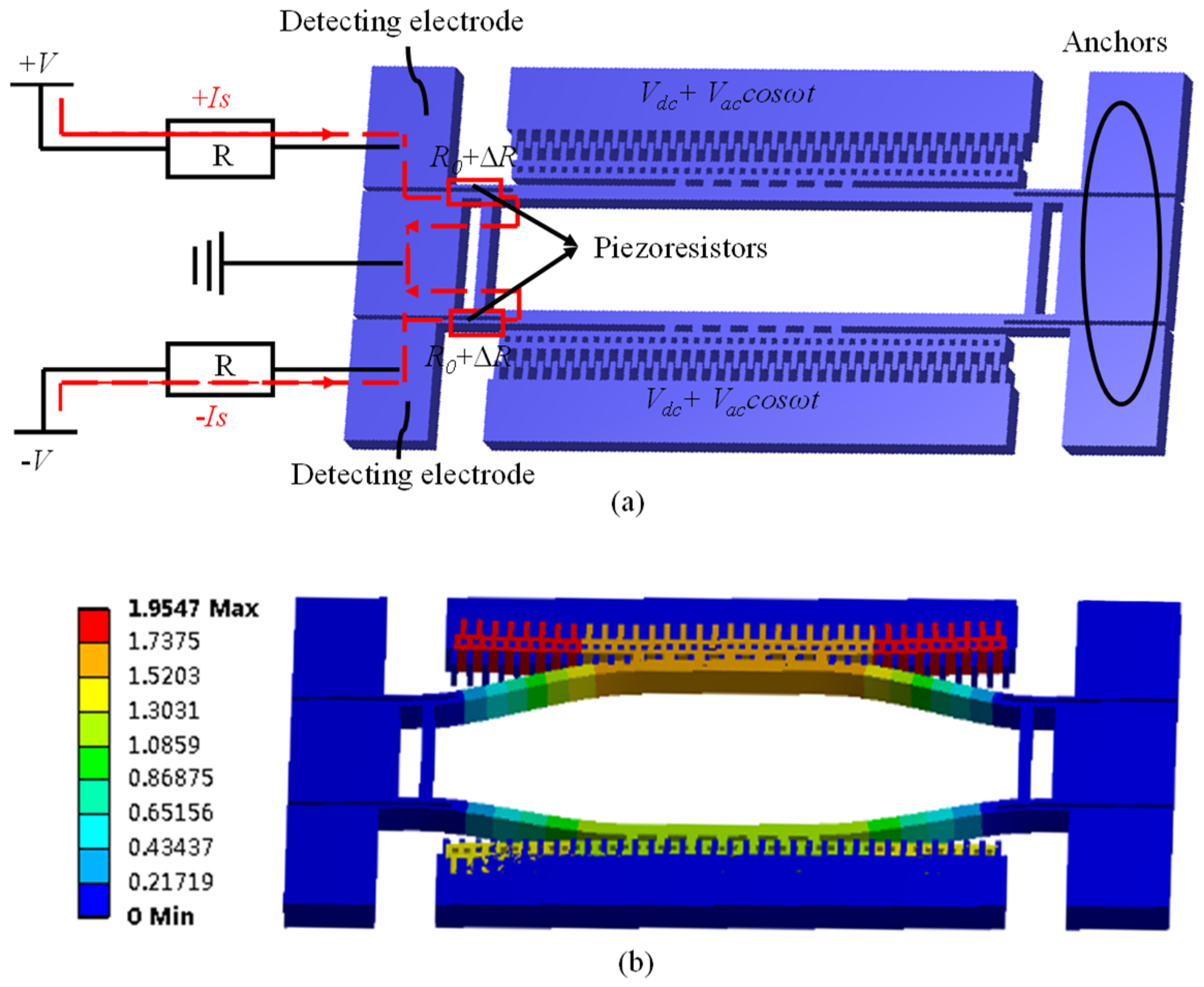
2. Design and Simulations
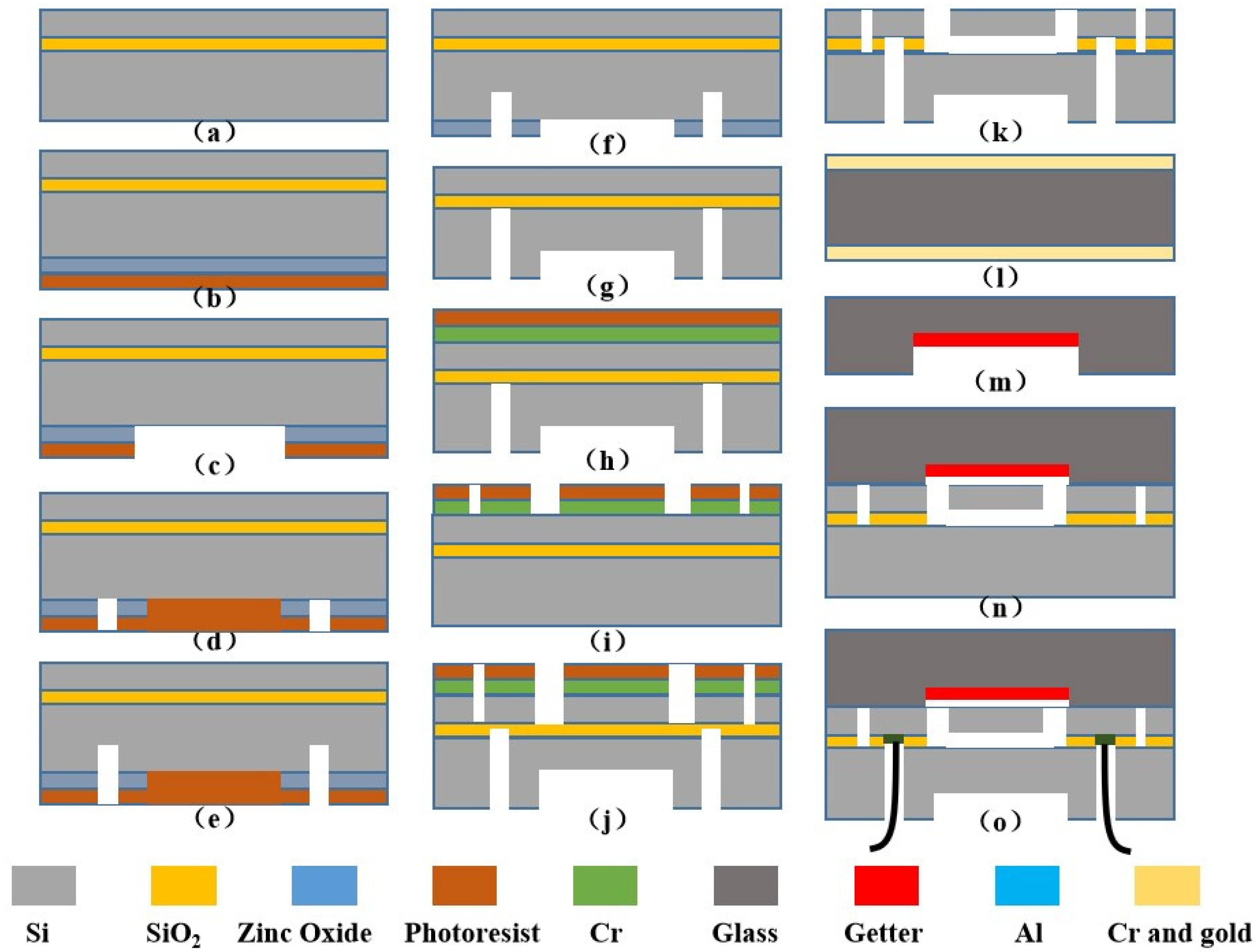
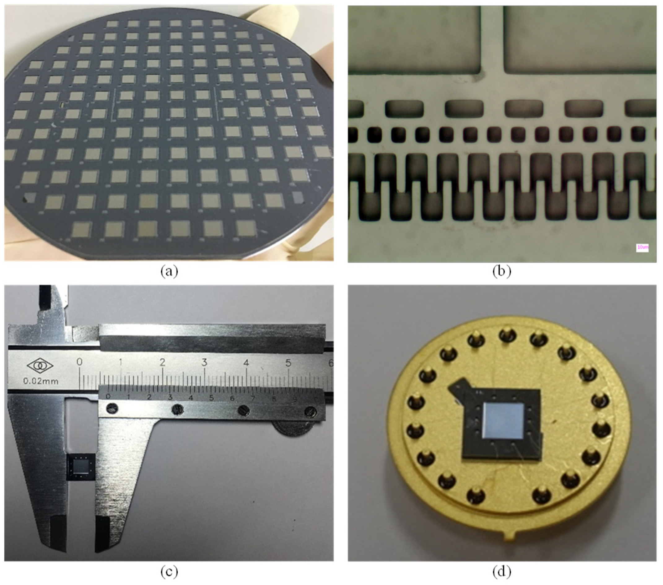
3. Fabrication
4. Results and Discussion
5. Conclusions
Author Contributions
Funding
Conflicts of Interest
References
- Eaton, W.P.; Smith, J.H. Micromachined pressure sensors: Review and recent developments. Smart Mater. Struct. 1997, 6, 530. [Google Scholar] [CrossRef]
- Věříš, J. Temperature compensation of silicon resonant pressure sensor. Sens. Actuators A 1996, 57, 179–182. [Google Scholar] [CrossRef]
- Tang, Z.; Fan, S.; Cai, C. A silicon micromachined resonant pressure sensor. In Journal of Physics: Conference Series; IOP Publishing: Bristol, UK, 2009; Volume 188, p. 012042. [Google Scholar] [CrossRef]
- Tang, Z.; Fan, S.; Xing, W.; Guo, Z.; Zhang, Z. An electrothermally excited dual beams silicon resonant pressure sensor with temperature compensation. Microsyst. Technol. 2011, 17, 1481. [Google Scholar] [CrossRef]
- Wang, J.; Shi, X.; Liu, L.; Zhengwei, W.; Deyong, C.; Jinmin, Z.; Shourong, L. A novel resonant pressure sensor with boron diffused silicon resonator. In Proceedings of the 2008 International Conference on Optical Instruments and Technology: MEMS/NEMS Technology and Applications, Beijing, China, 16–19 November 2008; p. 71590. [Google Scholar]
- Wang, J.; Chen, D.; Liu, L.; Zhengwei, W. A micromachined resonant pressure sensor with DETFS resonator and differential structure. In Proceedings of the IEEE Sensors, Christchurch, New Zealand, 25–28 October 2009; pp. 1321–1324. [Google Scholar]
- Chen, D.; Li, Y.; Liu, M.; Wang, J. Design and experiment of a laterally driven micromachined resonant pressure sensor for barometers. Procedia Eng. 2010, 5, 1490–1493. [Google Scholar] [CrossRef] [Green Version]
- Welham, C.J.; Greenwood, J.; Bertioli, M.M. A high accuracy resonant pressure sensor by fusion bonding and trench etching. Sens. Actuators A 1999, 76, 298–304. [Google Scholar] [CrossRef]
- Parsons, P.; Glendinning, A.; Angelidis, D. Resonant sensor for high accuracy pressure measurement using silicon technology. IEEE Aerosp. Electron. Syst. Mag. 1992, 7, 45–48. [Google Scholar] [CrossRef]
- Welham, C.J.; Gardner, J.W.; Greenwood, J. A laterally driven micromachined resonant pressure sensor. Sens. Actuators A 1996, 52, 86–91. [Google Scholar] [CrossRef]
- Greenwood, J.; Wray, T. High accuracy pressure measurement with a silicon resonant sensor. Sens. Actuators A 1993, 37, 82–85. [Google Scholar] [CrossRef]
- Xie, B.; Xing, Y.; Wang, Y.; Chen, J.; Chen, D.; Wang, J. A lateral differential resonant pressure microsensor based on soi-glass wafer-level vacuum packaging. Sensors 2015, 15, 24257–24268. [Google Scholar] [CrossRef] [PubMed]
- Shi, X.; Lu, Y.; Xie, B.; Li, Y.; Wang, J.; Chen, D.; Chen, J. A Resonant Pressure Microsensor Based on Double-ended Tuning Fork and Electrostatic Excitation Piezoresistive Detection. Sensors 2018, 18, 2494. [Google Scholar] [CrossRef] [PubMed]
- Luo, Z.; Chen, D.; Wang, J.; Li, Y.; Chen, J. A high-q resonant pressure microsensor with through-glass electrical interconnections based on wafer-level MEMS vacuum packaging. Sensors 2014, 14, 24244–24257. [Google Scholar] [CrossRef] [PubMed]
- Li, Y.; Wang, J.; Luo, Z.; Chen, D.; Chen, J. A resonant pressure microsensor capable of self-temperature compensation. Sensors 2015, 15, 10048–10058. [Google Scholar] [CrossRef] [PubMed]


© 2019 by the authors. Licensee MDPI, Basel, Switzerland. This article is an open access article distributed under the terms and conditions of the Creative Commons Attribution (CC BY) license (http://creativecommons.org/licenses/by/4.0/).
Share and Cite
Shi, X.; Zhang, S.; Chen, D.; Wang, J.; Chen, J.; Xie, B.; Lu, Y.; Li, Y. A Resonant Pressure Sensor Based upon Electrostatically Comb Driven and Piezoresistively Sensed Lateral Resonators. Micromachines 2019, 10, 460. https://doi.org/10.3390/mi10070460
Shi X, Zhang S, Chen D, Wang J, Chen J, Xie B, Lu Y, Li Y. A Resonant Pressure Sensor Based upon Electrostatically Comb Driven and Piezoresistively Sensed Lateral Resonators. Micromachines. 2019; 10(7):460. https://doi.org/10.3390/mi10070460
Chicago/Turabian StyleShi, Xiaoqing, Sen Zhang, Deyong Chen, Junbo Wang, Jian Chen, Bo Xie, Yulan Lu, and Yadong Li. 2019. "A Resonant Pressure Sensor Based upon Electrostatically Comb Driven and Piezoresistively Sensed Lateral Resonators" Micromachines 10, no. 7: 460. https://doi.org/10.3390/mi10070460