Formation Analysis of Edge Cracks of 33MnCrTiB Fork Steel

1
Department of Materials Science and Engineering, Hebei University of Engineering, Handan 056038, China
2
Warwick Manufacturing Group, University of Warwick, Coventry CV4 7AL, UK
*
Author to whom correspondence should be addressed.
Metals 2018, 8(8), 587; https://doi.org/10.3390/met8080587
Submission received: 4 July 2018
/
Revised: 18 July 2018
/
Accepted: 20 July 2018
/
Published: 27 July 2018
(This article belongs to the Special Issue 5th UK-China Steel Research Forum)
Abstract
:A 33MnCrTiB is a high-strength low alloy steel used for a forklift truck. This study investigates the root causes of the edge cracks in 33MnCrTiB steel produced by a steel manufacturer. After sampling, inspecting and analyzing the 33MnCrTiB flat steel with edge cracks taken from the plant, it was found that the crack and porosity contain similar residues to the deoxidation products and continuous casting mold flux. It can be concluded that the edge surface cracking in the flat steel are mainly caused by the non-deformable inclusions in steel, slag sticking and surface cracks on the original billet. At the same time, the further expansion of cracks is closely related to the serious decarburization during the heating treatment in the billet heating process, and the improper rolling deformation system during the rolling process.
1. Introduction
Forklifts are one of the indispensable tools in various fields of national economic production. In recent years, with the increasing use of forklifts in industrialized countries, the number of forklifts have increased. Fork steel is mainly used for the forklift truck and has high quality requirements, not only requiring high strength, but also needing a good plasticity index and a certain low temperature impact performance [1,2]. According to the survey, many researchers have found that the failure mode of mechanical parts used is mainly wear and fatigue [3,4,5]. A 33MnCrTiB is a high-strength low-alloy steel, after micro-alloying and quenching, can obtain good comprehensive mechanical properties to satisfy the requirements of the fork steel [6]. The surface quality of the product largely determines its performance, but the influence mechanism of the raw material quality on failure is not very clear. The in-depth analysis of raw material production process of the fork flat steel can further improve the comprehensive mechanical properties and application range of the product.
The surface of the 160 × 225 mm 33MnCrTiB rectangular billet produced by a steel mill in small batches has longitudinal cracks during the rolling process. After a preliminary examination of the batched of rolled steel samples, it was found that the cracks were mostly located at the edge in the center of the steel (thereafter called “edge cracks”), where there are obvious porosity and segregation. To obtain the causes of the surface longitudinal cracks in the 33MnCrTiB forklift flat steel, studies have been carried out on steel composition, hardness, microstructure, mold flux and inclusions, and corresponding measures have been formulated to increase the product quality. The research results are very useful for the development of high quality steel.
2. Research Plan
2.1. Production Process
The production process of the 33MnCrTiB alloy steel in the steel mill is:
Hot metal pretreatment → 70t Consteel arc furnace → 70t Ladle furnace → 160 × 225 mm Casting billet (with mold electromagnetic stirring) → Heating furnace → Rolling → Cooling → Finished product.
Serious defects such as edge cracks were found on the products after the rolling process. Chemical compositions of the samples taken from the defective products were analyzed firstly by using X-ray Fluorescence Spectroscopy and are shown in Table 1. It can be seen that the compositions of the samples with serious defects are within the specifications (Table 1), and no abnormal composition was found. Precise control of the trace elements Ti and B is particularly important in order to reduce the formation of nitrides in the steel, and Table 1 also shows the levels of Ti and B are within the specifications.
2.2. Research Methods
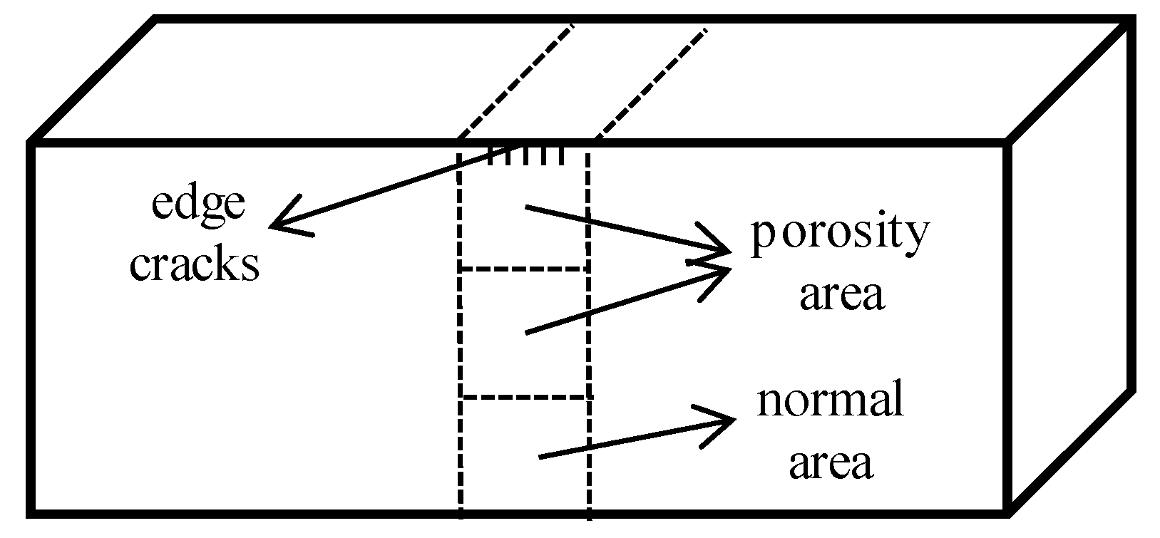
First, the hardness of the defect specimens was measured with a THR-150D electric Rockwell hardness tester. Then, the specimens were cut transversely along the longitudinal crack of target steel, two 15 mm × 15 mm square specimens were removed from the porosity area (see Figure 1). After grinding and polishing, the morphology and composition of the inclusions near the cracked area were observed in one sample on a ZEISS LSM700 scanning electron microscope, and the other was corroded with the diluted acid solution. The porosity, shrinkage cavity and the microstructure morphology of the samples were observed under an OLYMPUSDSX500 (OLYMPUS, Allentown, PA, USA) 3D optical digital microscope. In order to investigate the cause of the defect, a large sample electrolysis analysis was performed on the continuous casting billet in the same process. At the same time, the physicochemical properties of the mold flux were measured using an RTW-10 comprehensive physical property analyzer. On the basis of comprehensive analysis, the process parameters of continuous casting and rolling were adjusted, to eliminate surface cracking and porosity of 33MnCrTiB.
3. Experiment Results and Analysis
3.1. HRC Hardness Characterization
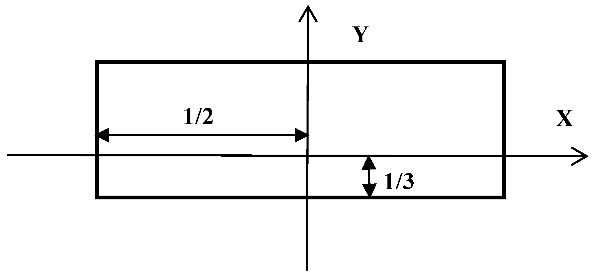
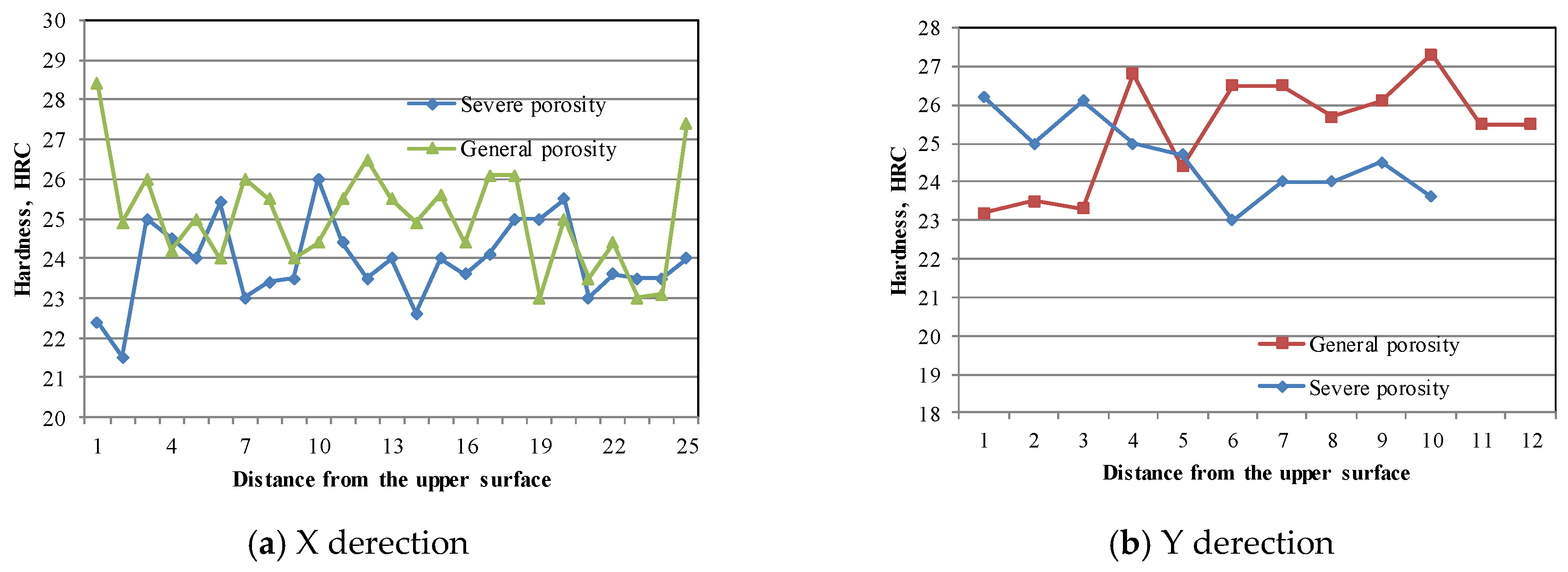
The finished fork requires a surface hardness of not less than 30 HRC [6]. The steel sample was taken along the rolling direction of the product and tested for whether the surface hardness meets the requirement. As shown in Figure 2, the long side and short side of the section orientations are defined as X-direction and Y-direction separately, and the measurement results are shown in Figure 3. In both figures “severe porosity” refers to the samples having severe porosity while “general porosity” refers to the samples having general porosity (it is relative to normal specimens).
As can be seen from Figure 3a, this batch of samples did not meet the requirement for surface hardness, and the hardness of the serious porosity samples in X-direction was significantly lower than that of the general porosity samples. In the crack-conspicuous area, it can be seen from Figure 3b that the hardness value of the porosity specimen in Y-direction is significantly lower than the hardness value of the general porosity specimen. This shows that there were tissue formation problems during the secondary cooling in the casting process or rapid cooling in the rolling process, especially in areas where morphology control in porosity area was not in place, and hardness was lower than normal surface texture.
3.2. Observation and Analysis of Microstructure
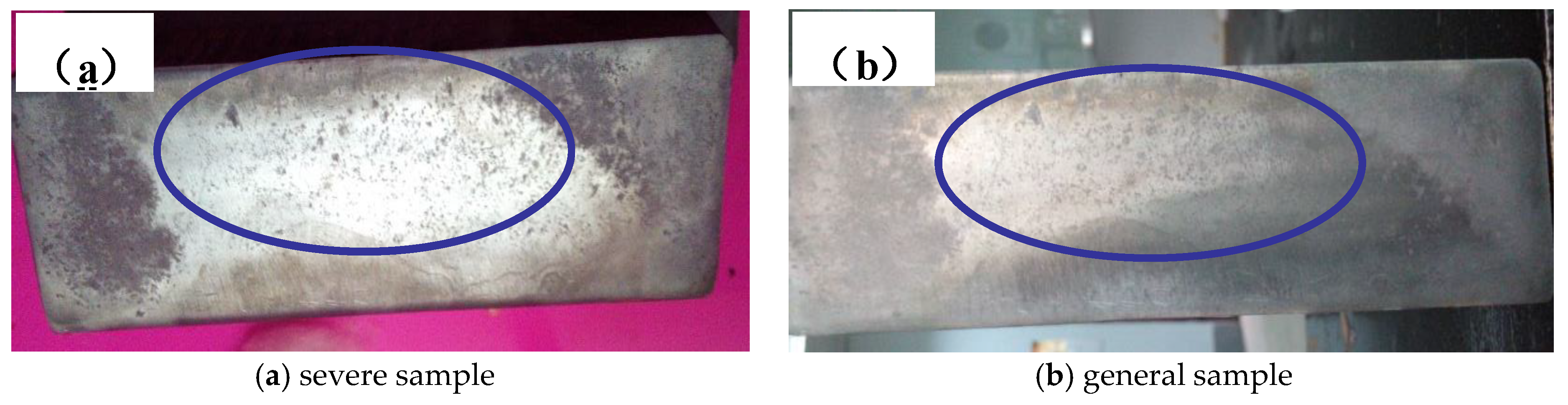
Macroscopic examination was carried out for the samples, which were etched by using the hydrochloric acid and stannous chloride solution. As shown in Figure 4, according to the observation of macro-corrosion samples, the center porosity is more serious. The center porosity is normally prevented by using electromagnetic stirring and rolling. The serious porosity in the center indicates that the electromagnetic stirring of the continuous casting billet and rolling compression ratio need to be improved, especially primary rolling deformation is insufficient.
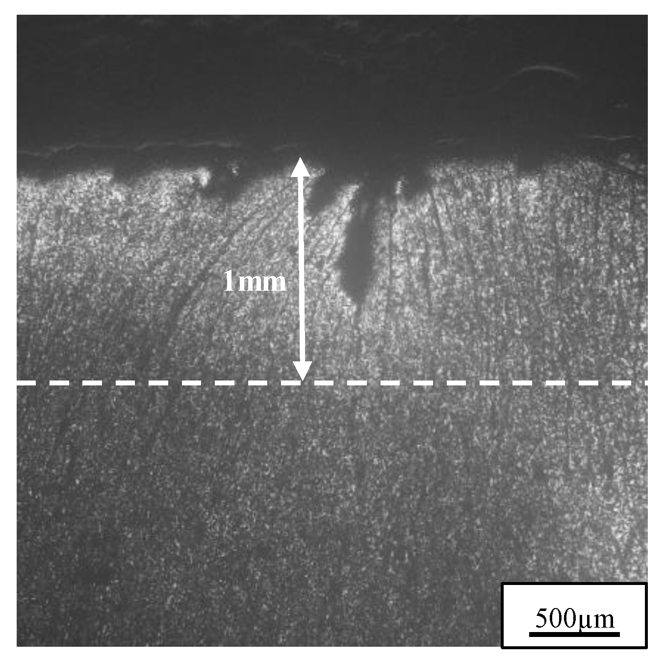
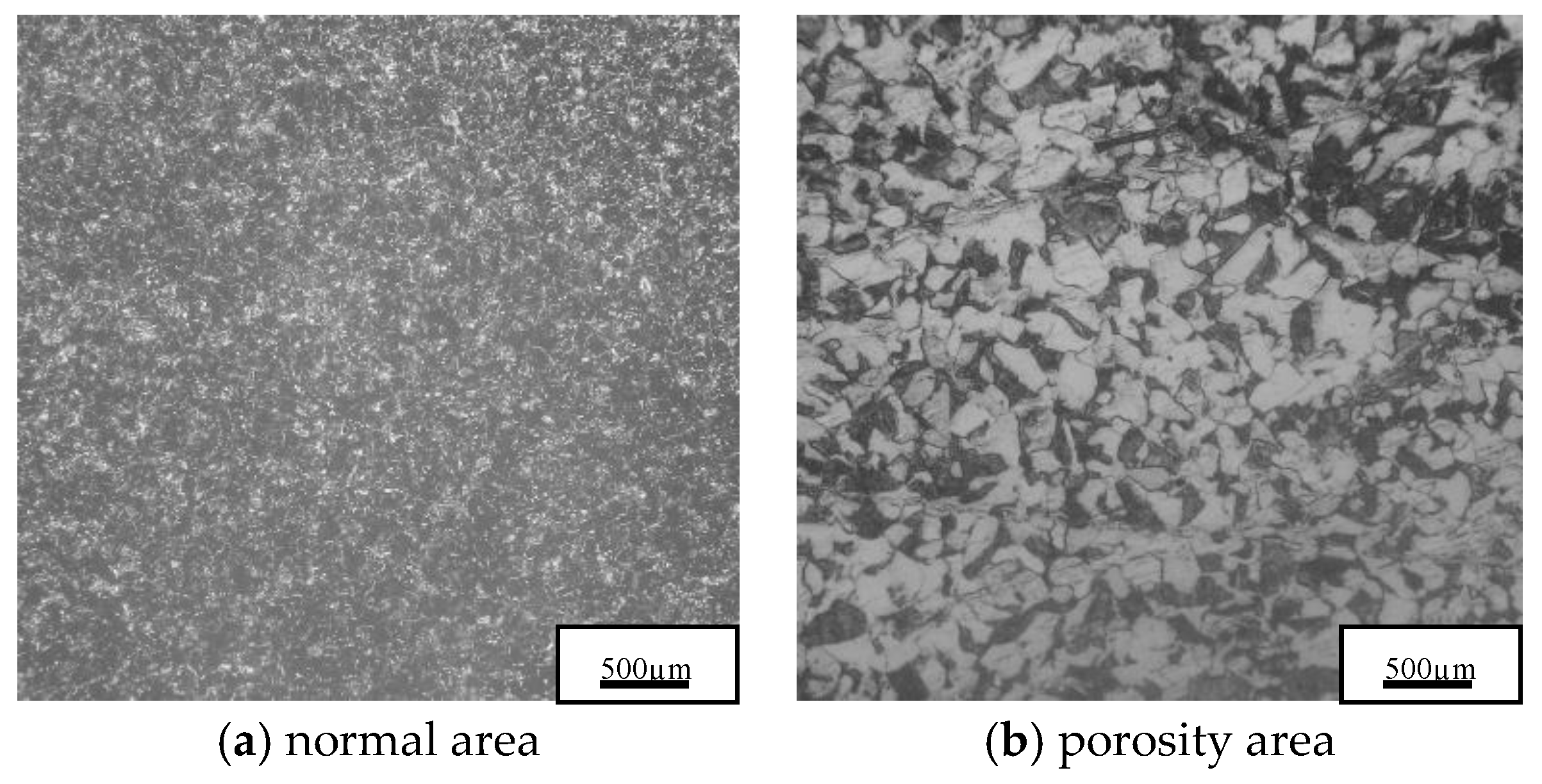
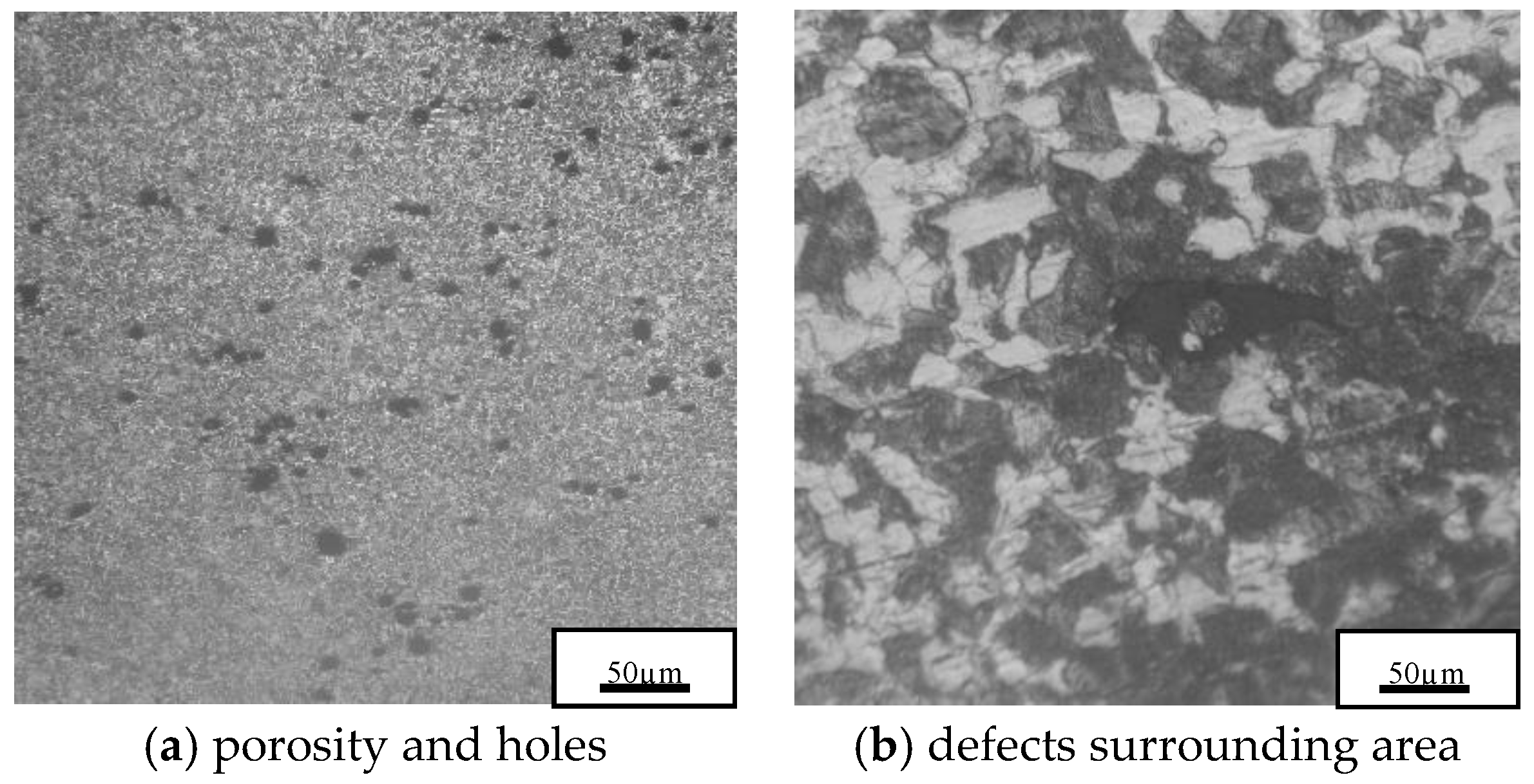
The sample is ground, polished, and etched with 4% nitric acid alcohol. Under optical microscope, as shown in Figure 5, a clear decarburization layer (500~1000 µm, bright layer) was observed on the surface of the crack source. However, the depth of decarburization layers and cracks are not equal, in other words, some cracks which are deeper than the decarburization layer originate from the billet. It indicates that they have been formed possibly in the billet before entering the heating furnace and extended during the rolling process, and it is also possible to cause decarburization by heating in a high-temperature furnace before steel rolling. According to Figure 6, compared with the morphology in normal area, there are many pits and attachments on the surface of the 33MnCrTiB in the defect area, and the number of pits and attachments is very large; the voids of the general porosity samples are relatively few. According to the metallographic observation, the normal matrix of the cross section should be fine sorbite and a small amount of ferrite, but the loose morphology is mainly a large number of ferrite and a small amount of sorbate. It can be seen from Figure 7 that there are many voids and adherents on the substrate of the defective sample, and there are suspected large external inclusions in the hole, which need to be confirmed by electron microscopy analysis (see Section 3.3 Inclusion Analysis).
3.3. Inclusions Analysis
3.3.1. Macro-Inclusions in Casting Billet
In order to determine the possibility of cracks and holes caused by the inclusions, first, the 33MnCrTiB samples were prepared and analyzed in the laboratory, and the focus was on the analysis of external inclusions in flat steel with large sample electrolysis. In this study, a 33MnCrTiB round billet was sampled from the steel mill, and it was cut and surface cleaned to meet the sample requirements for large sample electrolysis. Then the electrolysis sample was electrolyzed by sulfate solution in the laboratory. The weight and classification of large oxide inclusions obtained in the sample are shown in Table 2 after electrolysis.
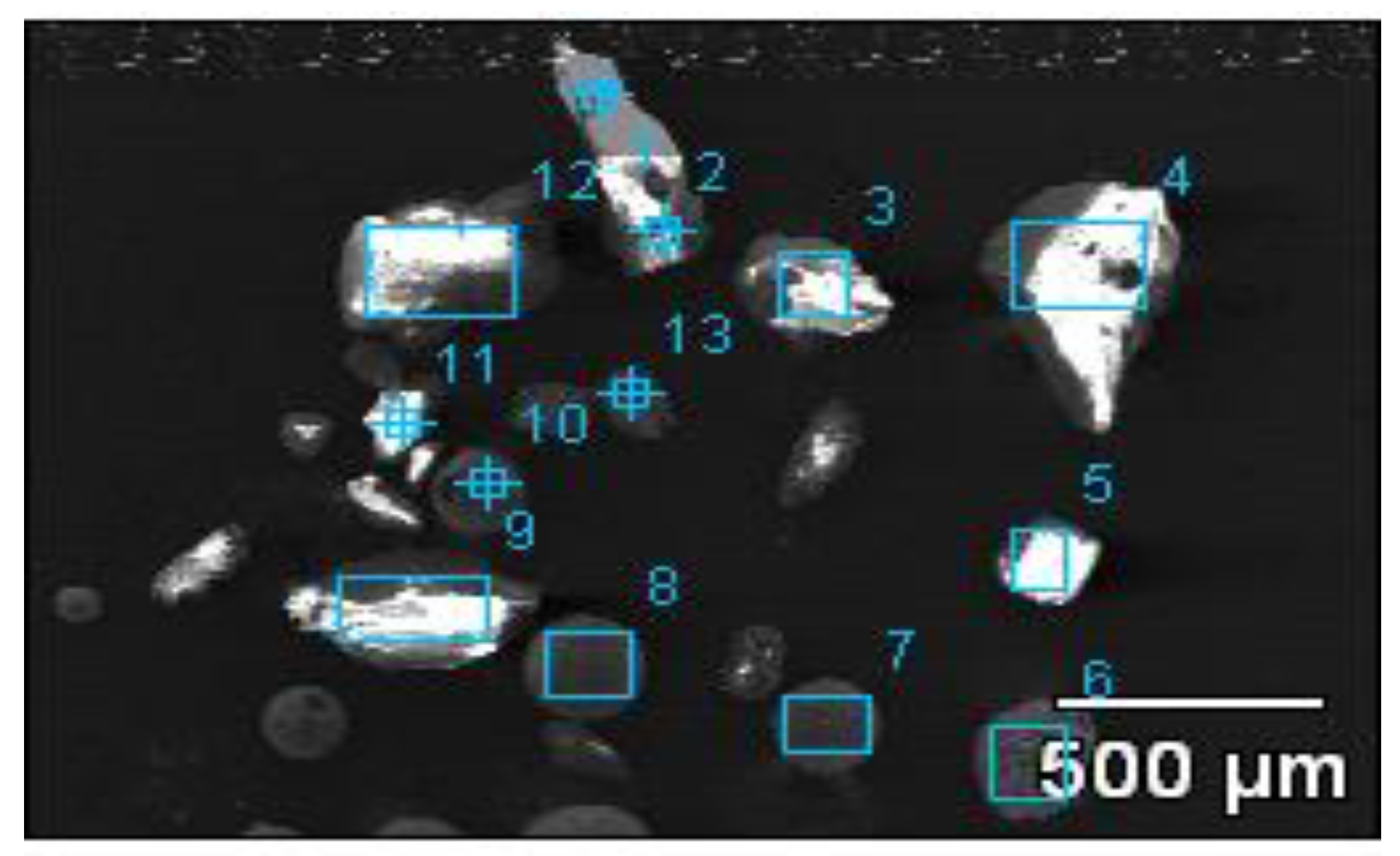
The large inclusions in electrolysis samples were observed using a Japanese JSM-6480LV scanning electron microscope with energy dispersive spectrometer (EDS), and EDS analysis of the inclusion components was performed. The morphology of the large inclusions is shown in Figure 8, and the compositions of the individual inclusions labelled in Figure 8 are listed in Table 3 respectively.
Through scanning electron microscope observation of electrolysis sample, it can be concluded that the main inclusions of the electrolysis sample are CaO–MgO–Al2O3–SiO2–TiO2, CaO–Al2O3–SiO2–TiO2, Al2O3, and CaO–Al2O3 oxides. There are also less ZnO, K2O, etc in some inclusions; there is also a small amount of precipitate sulfide inclusions such as MnS and CuS in the sample. There are many large inclusions in billet sample, with a size of more than 140 μm and a smaller size of about 80 μm. Such large-scale oxide inclusions are harmful to the cutting performance, welding performance and corrosion resistance of the steel. These kinds of inclusions destroy the continuity of the steel matrix and affect the relevant properties of the steel. Most of the defects on the surface of the steel, such as buckling, scabs, unevenness and cracks, are related to large oxide inclusions. The presence of sulfide inclusions in steel can cause hot brittleness of the steel, affecting the plasticity and toughness of the steel.
3.3.2. Micro-Inclusions in Rolling Fork Steel
Micro-Inclusions in Severe Porosity Samples
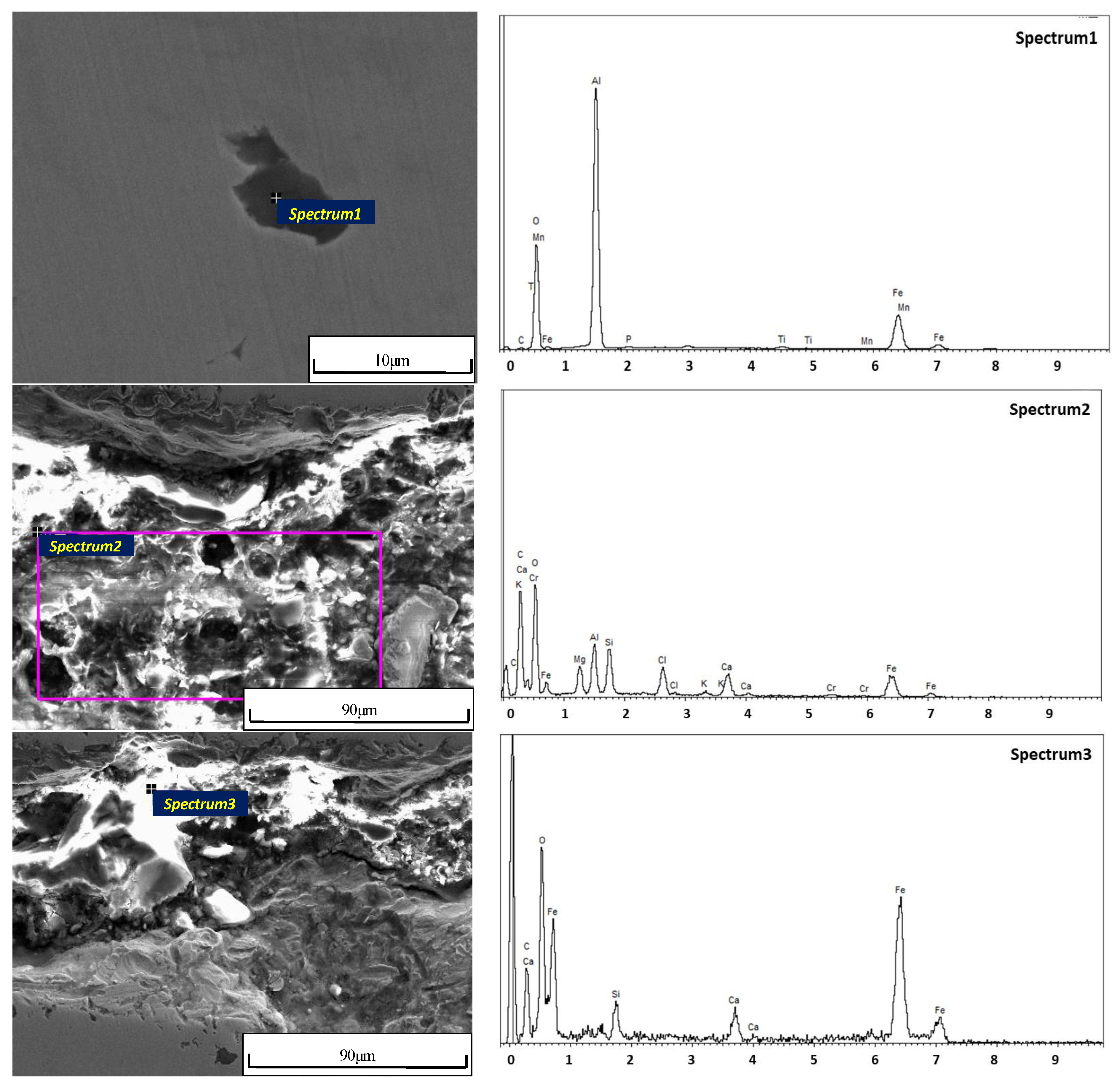
In order to determine the typical inclusion compositions of the steel in severe porosity samples, the EDS analysis of micro-inclusions was performed. Then the microscopic morphology and inclusion distribution were observed in 33MnCrTiB steel sample with serious defects, as shown in Figure 9. It indicated that the defects are irregularly distributed, and there are a large number of pits and massive inlays on the surface.
Figure 9 shows that the typical inclusions in severe porosity sample of 33MnCrTiB steel are mainly classified into four types: (1). Ti(C,N) inclusions, <10 μm in size; (2). MnS inclusions, <10 μm in size; (3). large Al2O3 inclusions; (4). CaO–MnO–MgO–SiO2–Al2O3– (Na2O+K2O) inclusions. Among them, the first three kinds of inclusions belong to secondary oxidation products and precipitates during solidification, which indicates that the composition of the submerged arc slag and the timing of alloy addition are not reasonable. Due to the insufficient T[O] removal and air inhalation during the operation, the atmospheric oxidation of Ti in the liquid steel was severe, and it was difficult to eliminate a large amount of the inclusions without sufficient soft inertial gas blowing time. The fourth type of large inclusions, judged from its composition, is caused by the entrapment of mold fluxes. This implies that potential issues exist for the composition of mold flux of this type of steel and mold flux behavior in the casting mold. The slag entrapment with the continuous casting shell likely occurred, which needs to optimize.
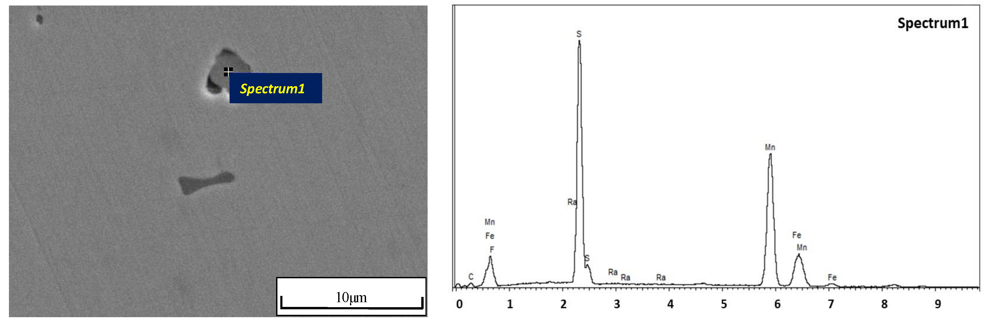
According to the EDS results of the inclusion (Figure 10), it can be found that the typical inclusions in 33MnCrTiB cracks are mainly three types: (1). Al2O3–(TiC) inclusions with a size of about 10 μm; (2). CaO–SiO2–Al2O3–MgO–K2O inclusions; and (3). large CaO–SiO2 inclusions. The first type is an aluminum oxide reaction product. According to the composition of the inclusions, it is determined that the inclusions are high-melting point hard inclusions and should be generated by the primary or secondary de-oxidation process. The size of the 2nd and 3rd inclusions is relatively large. The existence of the inclusions indicates that slagging phenomenon occurred in the mold during the casting process, or the refractory materials of the tundish fell off.
Inclusions in General Porosity Samples
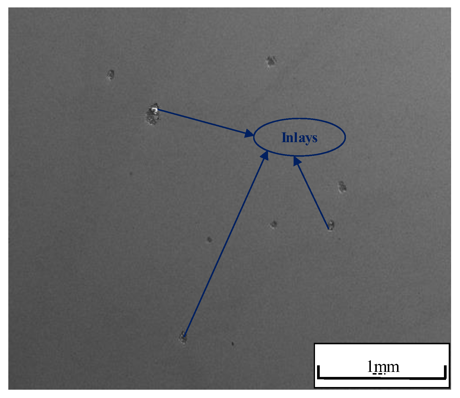
Figure 11 shows the macroscopic morphology and inclusion distribution of 33MnCrTiB with general porosity. It can be seen that the number of inclusions is relatively small and the distribution is irregular. There are also a large number of pits and massive inlays on the surface. In order to determine the typical inclusion compositions of the steel, EDS analysis of micro inclusions is required.
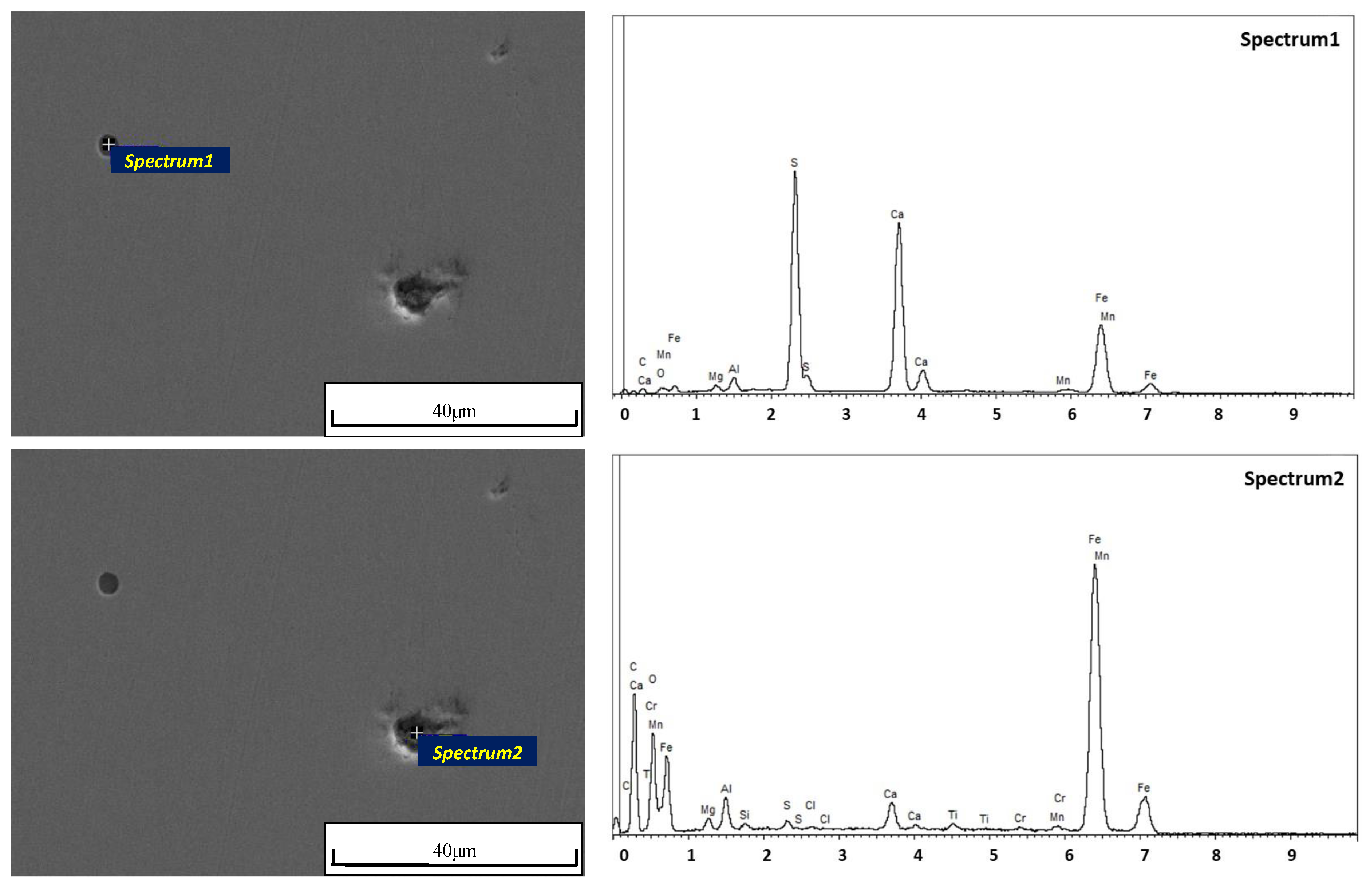
According to the Figure 12 analysis, the typical inclusions in normal 33MnCrTiB samples are mainly three types: (1). Ti(C,N)–MnS inclusions with a size of about 10 μm; (2). CaO–MgO–MnO–SiO2–Al2O3–TiO2 inclusions with a size of less than 10 μm; (3). large CaS and MnS inclusions. Among them, the first two kinds are steel-slag reactions and solidification precipitation products. According to the inclusions, it is determined that the inclusions are in the high melting point region of the phase diagram and should be formed into molten steel due to poor melting performance of refining slag. The presence of third type of inclusions indicates that the desulfurization of molten steel was not complete and the amount of calcium added was too high.
3.4. Mold Flux Analysis
Because the inclusions containing the composition of mold flux were found in the casting products (before reheating-rolling) and rolled material, the possibility of cracks in the cast slab was analyzed based on the existing performance problems with the mold flux. If the mold flux is poor in performance, it stuck on the surface of the billet, resulting in inhomogeneous cooling of the billet in the secondary cooling zone, the shells with large cooling strength had the large shrinkage and produced tensile stress at low cooling strength and small shrinkage of the shell. As a result, the billet in the slag-sticking part was prone to vertical cracks [7]. Because of the uneven distribution of slag and the coverage of the iron oxide sheet, the formed cracks were relatively small and not easily detected. The two kinds of mold fluxes are provided with two mold flux suppliers (supplier A and supplier B) to the steel mill in the actual application, and their performances are listed in Table 4. When the fixed carbon and melting point of flux are too high, and the viscosity is large, the phenomenon of slag sticking is likely to occur [8]. The fixed carbon content of the above-mentioned mold flux is too high, so the melting speed is slower, the melting point and viscosity is higher, so it is difficult to meet the requirements of high casting speed of steel grades.
In actual production, the fixed carbon content of mold flux should match the casting speed of continuous casting. High-carbon steel generally adopts a weak cooling and low-speed casting process to improve the internal quality of the slab. At the same time, the mold flux with a higher carbon content is used. For medium-carbon steel, a mold flux with a lower carbon content is used. In addition, the slow melting of mold flux makes the liquid slag layer thin and can easily cause slag entrapment on the surface of the billet [9]. The mold flux has a high melting point and a high viscosity, which can easily lead to slag adhesion on the surface of the billet and cause unequal cooling of the billet, the tendency of longitudinal cracks is increased [10]. In combination with actual production, the surface temperature of the slab when it emerges from the crystallizer is generally in the range of 1200 °C to 1250 °C, and the melting point of the mold flux should be lower than the surface temperature of the billet to make the residue fall off. Therefore, the principle of adjusting the physical and chemical properties of mold flux is to increase the alkalinity of slag system and the melting point of the mold flux should be controlled below 1100 °C. There are two main functions [11]: firstly, reducing the viscosity to meet the requirement of high casting speed for the mold flux, and second, increasing the crystallization temperature of mold flux by improving the alkalinity. Increasing the crystal phase in the solid phase layer of the mold flux improve the thermal resistance of the mold powder and reduces the heat flow, so as to prevent the occurrence of longitudinal cracks of the shell in the mold due to excessive cooling.
4. Conclusions
According to the above analysis, the formation causes and control measures of cracks in the 33MnCrTiB fork steel produced by a steelmaker have the following four aspects:
- (1)
- A large number of micro-inclusions with size below 10 μm Ti(C,N), CaO–MgO–SiO2–Al2O3–TiO2 and CaS–MnS are found in the porosity steel. It indicates that there are some problems with slagging and calcium treatment process. The more than 50 μm inclusions of CaO–Al2O3–SiO2–TiO2–(MgO), Al2O3, and CaO–Al2O3 oxides are also found in the billets, these large inclusions may become the sources of small cracks in the rolling process.
- (2)
- The unstable crystallizer liquid level and the unqualified mold flux in continuous casting process lead to the slag entrapment on the liquid surface or slag sticking on the billet shell, resulting in CaO–MgO–SiO2–Al2O3–K2O–Na2O inclusions remained in surface cracks.
- (3)
- The process from continuous casting through reheating to rolling was not coordinated, rolling deformation was not uniform, so that the segregation and porosity are difficult to reduce, then porosity deviation from the center occurs to induce new cracks.
- (4)
- The inclusions must be removed in the refining process, especially the large D and Ds inclusions. It is necessary to stabilize the casting speed, and keep the liquid level of the crystallizer stable. A mold flux having a suitable viscosity, a fast melting rate, a low melting point and C content should be selected. The surface defects of the slab need be cleaned in time, and the compression ratio and cooling strength of each rolling process should be strictly controlled to ensure the deformation of the core of the slab.
Author Contributions
Methodology and Investigation, S.Z. and Y.G.; Data Curation, L.M. and T.Y.; Project Administration, J.L.; Funding Acquisition, S.Z. and T.Y.; Writing-Original Draft Preparation, S.Z.; Results Discussion, Writing-Review and Editing, Z.L.
Funding
The authors would like to appreciate the support from Iron and Steel Joint Foundation of Hebei Province (E2016402096, E2016402111), Higher Education Teaching Reform Project of Hebei Province (2017GJJG129) and Transformation Foundation of Scientific and Technological Achievements.
Acknowledgments
The authors would like to highly appreciate the support from Iron and Steel Joint Foundation of Hebei Province (E2016402096, E2016402111) and Higher Education Teaching Reform Project of Hebei Province (2017GJJG129).
Conflicts of Interest
The authors declare no conflict of interest.
References
- Yin, X.G.; Wang, G.; Zhang, X.H. Development of Low Alloy High Strength Fork Flat Steel. Mod. Metall. 2009, 37, 13–15. [Google Scholar]
- Zhang, Y.S. Analysis of Structure and Performance of 15B37HC Fork Special Steel. Mod. Metall. 2011, 39, 8–11. [Google Scholar]
- Lu, S.S.; Ze, X.B.; Fu, X.L. Study on the Surface Layer Microhardness of 40Cr by Ultrasonic Finishing and Reinforcing Process. Modul. Mach. Tool Autom. Manuf. Tech. 2014, 12, 27–33. [Google Scholar]
- Auezhan, A.; Oleksiy, V.P.; Young, S.P.; Dae, E.K. Effects of Ultrasonic Nanocrystalline Surface Modification on the Tribological Properties of AZ91D Magnesium Alloy. Tribol. Int. 2012, 54, 106–113. [Google Scholar]
- Lu, S.S.; Fu, X.L.; Ze, X.B. Experimental Study on the Surface Roughness of 40Cr by Ultrasonic Finishing Machining. Appl. Mech. Mater. 2014, 470, 577–580. [Google Scholar] [CrossRef]
- Geng, Z.M.; Ren, X.P.; Liu, H.J. Reason Analysis for Fatigue Test Failure of Goods Fork. Hebei Metall. 2014, 22, 27–29. [Google Scholar]
- Yuan, J.L.; Li, W.X.; Niu, S.Z. Research on Longitudinal Surface Cracking of 40Cr Bar. Iron Steel 2006, 41, 36–39. [Google Scholar]
- Jiang, X.D. Cause and Control on Slab Longitudinal Surface Crack. Contin. Cast. 2003, 6, 27–29. [Google Scholar]
- Cai, K.K. The Principle and Technique of Continuous Casting; Metallurgical Industry Press: Beijing, China, 1994; ISBN 9787502414573. [Google Scholar]
- Li, B.Z. Study on Surface Inclusion and Crack of Continuous Cast Slab. Contin. Cast. 2003, 3, 35–36. [Google Scholar]
- Wang, H.F. Selection on Mould Powder for High Speed Casting. Contin. Cast. 2004, 1, 39–43. [Google Scholar]
Figure 1.
Sampling position.

Figure 2.
X-direction and Y-direction in the samples.

Figure 3.
Hardness distribution of normal and defective specimens in different directions.

Figure 4.
The 33MnCrTiB macro-corrosion morphology.

Figure 5.
Surface decarburization layer in crack source area.

Figure 6.
Low magnification microstructure of (a) normal area and (b) defective area.

Figure 7.
Magnified morphology of microstructure in cracks and holes area.

Figure 8.
Morphology of macro-inclusions in sample.

Figure 9.
Morphology and composition of micro-inclusions in severe porosity steel.


Figure 10.
Morphology and compositions of microscopic inclusion in cracks.

Figure 11.
Macroscopic distribution of inclusions in general porosity steel.

Figure 12.
Morphology and distribution of microscopic inclusions in general porosity steel.


Table 1.
Chemical composition of defective product and specifications for 33MnCrTiB, wt-%.
| C | Si | Mn | P | S | Cr | Ti | B | |
|---|---|---|---|---|---|---|---|---|
| Defective | 0.33 | 0.26 | 1.36 | 0.011 | 0.005 | 0.4 | 0.034 | 0.0013 |
| Standard | 0.30~0.35 | 0.17~0.37 | 1.25~1.50 | ≤0.035 | ≤0.035 | 0.30~0.60 | ≥0.015 | 0.0005~0.0030 |
Table 2.
Analysis results of large oxide inclusions in steel.
| Original Weight | Remaining Weight | Electrolytic Weight | Total Weight of Inclusions | Size Classification, µm | ||||
|---|---|---|---|---|---|---|---|---|
| <80 | 80~140 | 140~300 | >300 | |||||
| kg | kg | kg | mg | mg/10 kg | mg | mg | mg | mg |
| 4.438 | 0.251 | 4.178 | 2.60 | 6.21 | 0.10 | 0.20 | 1.20 | 1.10 |
Table 3.
Composition analysis of each inclusion in Figure 8, wt-%.
Table 3.
Composition analysis of each inclusion in Figure 8, wt-%.
| O | Mg | Al | Si | S | K | Ca | Ti | Cr | Mn | Fe | Cu | Zr | |
|---|---|---|---|---|---|---|---|---|---|---|---|---|---|
| 1 | 50.85 | 1.33 | 12.76 | 23.22 | 3.22 | 3.05 | 1.85 | 0.52 | 3.2 | ||||
| 2 | 60.39 | 22.58 | 3.21 | 5.03 | 1.71 | 7.09 | |||||||
| 3 | 50.12 | 0.85 | 23.33 | 12.08 | 1.62 | 3.87 | 3.06 | 5.09 | |||||
| 4 | 45.98 | 34.43 | 7.55 | 0.98 | 0.95 | 2.31 | 0.51 | 7.28 | |||||
| 5 | 60.89 | 21.2 | 2.61 | 9.83 | 5.46 | ||||||||
| 6 | 20.85 | 2.03 | 7.18 | 1.03 | 1.11 | 6.03 | 6.56 | 3.46 | 5.01 | 46.7 | |||
| 7 | 29.42 | 8.6 | 24.96 | 0.78 | 2.15 | 11.16 | 12.71 | 7.78 | 2.45 | ||||
| 8 | 24.45 | 3.47 | 25.24 | 0.86 | 18.2 | 18.15 | 2.19 | 7.44 | |||||
| 9 | 48.79 | 51.21 | |||||||||||
| 10 | 14.14 | 1.09 | 23.22 | 3.56 | 5.47 | 32.27 | 14.55 | 5.7 | |||||
| 11 | 44.09 | 55.91 | |||||||||||
| 12 | 60.67 | 20.78 | 10.03 | 8.52 | |||||||||
| 13 | 42.75 | 32.08 | 25.17 |
Table 4.
Compositions and performance of mold flux.
| Compositions, wt-% | Physical Performance | |||||||||||
|---|---|---|---|---|---|---|---|---|---|---|---|---|
| SiO2 | CaO | MgO | Fe2O3 | Al2O3 | MnO | Na2O | F | C | H2O | Melting Point, °C | Viscosity, Pa·S | |
| Supplier A | 28.8 | 25.0 | 1.6 | 2.6 | 10.3 | 0.2 | 3.3 | 5.3 | 21.5 | 0.1 | 1189 | 0.79 |
| Supplier B | 28.6 | 24.1 | 3.6 | 0.9 | 6.3 | - | 6.5 | 1.4 | 19.1 | 0.4 | 1166 | 0.69 |
© 2018 by the authors. Licensee MDPI, Basel, Switzerland. This article is an open access article distributed under the terms and conditions of the Creative Commons Attribution (CC BY) license (http://creativecommons.org/licenses/by/4.0/).
Share and Cite
MDPI and ACS Style
Zhao, S.; Ge, Y.; Ma, L.; Yan, T.; Lyu, J.; Li, Z. Formation Analysis of Edge Cracks of 33MnCrTiB Fork Steel. Metals 2018, 8, 587. https://doi.org/10.3390/met8080587
AMA Style
Zhao S, Ge Y, Ma L, Yan T, Lyu J, Li Z. Formation Analysis of Edge Cracks of 33MnCrTiB Fork Steel. Metals. 2018; 8(8):587. https://doi.org/10.3390/met8080587
Chicago/Turabian StyleZhao, Shuo, Yangyang Ge, Liang Ma, Tao Yan, Jingcai Lyu, and Zushu Li. 2018. "Formation Analysis of Edge Cracks of 33MnCrTiB Fork Steel" Metals 8, no. 8: 587. https://doi.org/10.3390/met8080587
Note that from the first issue of 2016, this journal uses article numbers instead of page numbers. See further details here.