An Overview of Fatigue Strength of Case-Hardening TRIP-Aided Martensitic Steels


1
Department of Mechanical Systems Engineering, School of Science and Technology, Shinshu University, Nagano 380-8553, Japan
2
Institute for Materials Research, Tohoku University, Sendai 980-8577, Japan
3
Department of Metallurgical and Materials Engineering, School of Engineering, OP Jindal University, Raigarh 496001, India
*
Author to whom correspondence should be addressed.
Metals 2018, 8(5), 355; https://doi.org/10.3390/met8050355
Submission received: 19 April 2018
/
Revised: 3 May 2018
/
Accepted: 5 May 2018
/
Published: 15 May 2018
(This article belongs to the Special Issue Performance of Mechanical Properties of Ultrahigh-Strength Ferrous Steels Related to Strain-Induced Transformation)
Abstract
:Surface-hardened layer characteristics and fatigue strength properties of transformation-induced plasticity-aided martensitic steels subjected to heat-treatment or vacuum carburization followed by fine-particle peening are revealed for automotive applications specially for powertrain parts. The as-heat-treated steels without the case-hardening process possess excellent impact toughness and fatigue strength. When the steels are subjected to fine-particle peening after heat-treatment, the fatigue limits of smooth and notched specimens increase considerably, accompanied with low notch sensitivity. Vacuum carburization and subsequent fine-particle peening increases further the fatigue strength of the steels, except notch fatigue limit. The increased fatigue limits are principally associated with high Vickers hardness and compressive residual stress just below the surface, resulting from the severe plastic deformation and the strain-induced martensitic transformation of metastable retained austenite, as well as low surface roughness and fatigue crack initiation depth.
1. Introduction
Recently, four types of transformation-induced plasticity (TRIP)-aided steels with different matrix structures and different chemical compositions, namely “TRIP-aided bainitic ferrite (TBF) steel” [1,2,3,4,5,6,7,8,9,10], “TRIP-aided martensitic (TM) steel” [11,12,13,14,15,16,17,18,19,20,21], “quenching and partitioning (Q&P) steel” [22,23,24,25,26,27,28,29,30,31], and “medium Mn TRIP-aided steel” [32,33,34,35,36,37,38,39] have been developed as third-generation advanced high-strength steels (AHSSs) for automotive sheet products. These steels possess high toughness, fatigue strength and delayed fracture strength, as well as excellent cold formability, especially in TM steels [7,11,16,17,18,19,20]. Therefore, these steels are expected to be also a suitable material for high torque powertrain parts which are produced by cold and hot forging [40], in the same way as “nanostructured bainitic steel” [41,42,43,44,45,46,47,48].
Many researchers found that shot peening considerably increases the fatigue strength of the conventional case-hardening martensitic steels [49,50,51,52,53,54,55,56,57,58,59]. Sugimoto et al. [60,61,62] have reported that high fatigue strength and low notch-sensitivity for fatigue of the TM steel are achieved by fine-particle peening and/or vacuum carburization because of small surface roughness and the improved surface-hardened layer properties. In addition, they showed that further increase in fatigue limit of the steels is achieved by using of multi process of vacuum carburization and fine-particle peening which increases the hardness and residual stress in the surface hardened layer [63,64,65].
In this paper, microstructural properties (matrix, second phase and retained austenite characteristics), mechanical properties (tensile, impact and fatigue properties) and relationships between the microstructural and mechanical properties of as-heat-treated (0.1–0.6)%C–1.5%Si–1.5%Mn–Cr–Mo–Ni TM steels are first introduced to understand the internal characteristics of case-hardening TM steel. Next, surface-hardened layer properties and fatigue strength of 0.2%C–1.5%Si–1.5%Mn–1.0%Cr–(0–0.2)%Mo TM steels subjected to heat-treatment or vacuum-carburization followed by fine-particle peening are explained. Besides, the fatigue strength properties are mainly correlated with the Vickers hardness and the residual stress in the surface-hardened layer which are enhanced by the strain-induced martensite transformation of metastable retained austenite and severe plastic deformations, as well as the surface roughness and fatigue crack initiation depth. This review paper is based on our researches referring to the fatigue strength of TM steels because no researcher could identify and address potential issues.
2. As-Heat-Treated TM Steels
2.1. Microstructure
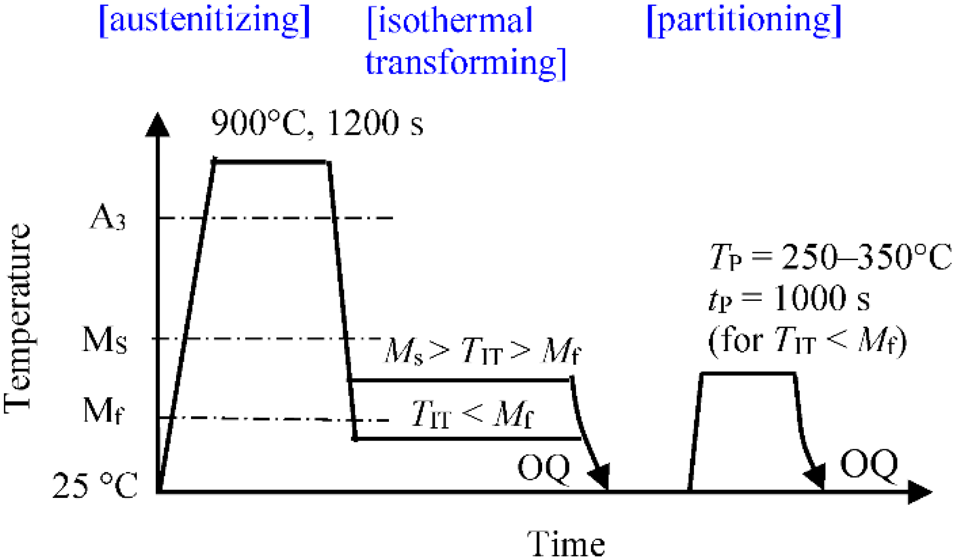
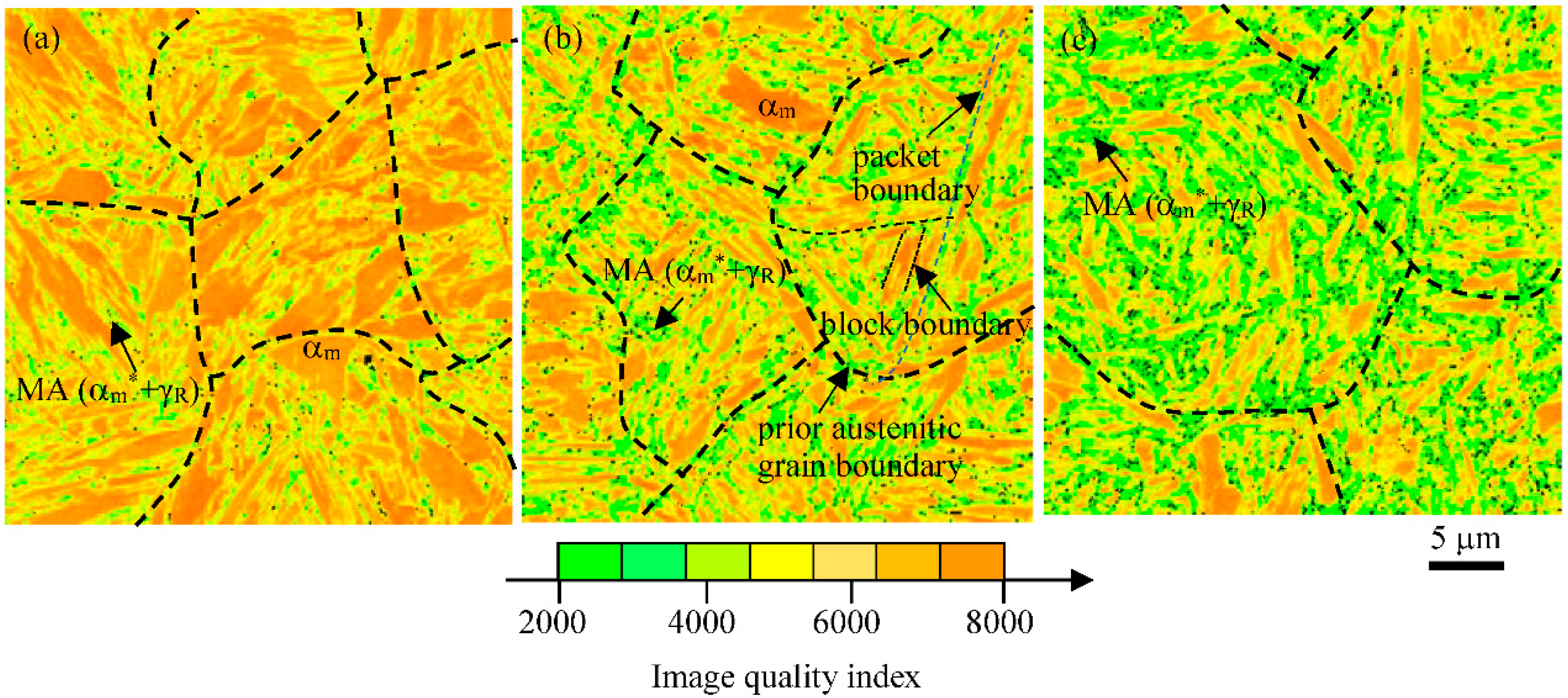
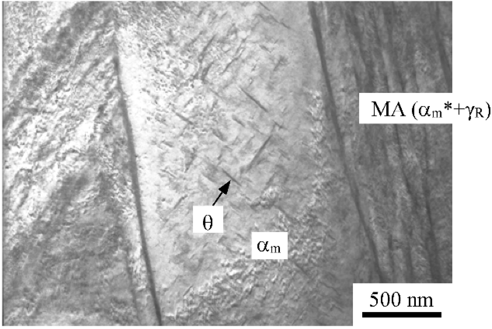
C−Si−Mn−Cr−Mo−Ni TM steels with tensile strength higher than 1470 MPa can be produced by the multi-step heat-treatment consisting of austenitization and subsequent isothermal transformation at temperature below martensite-finish temperature (Mf) shown in Figure 1 [11,12,13,14,15,16,17,18,19,20,21]. On cooling to the isothermal transformation temperature, most of the austenite first transforms to soft α′-martensite with wide lath structure, with a small amount of untransformed austenite. On subsequent cooling after isothermal transformation, the austenite changes into a mixture of hard α′-martensite with narrow lath structure and carbon-enriched retained austenite (MA)-like phase. Resultantly, microstructure of the TM steels principally consists of soft α′-martensite matrix and MA-like phase (Figure 2) [13]. Most of the MA-like phases are located on prior austenitic grain, packet and block boundaries. The retained austenite phases are mainly filmy and in existence along narrow lath-martensite boundary in the MA-like phase, as shown in Figure 3. Fine and needle shaped carbides seem to precipitate only in wide lath-martensite structure. This means that the carbides are already precipitated during auto-tempering on quenching prior to low temperature isothermal transformation. It is noteworthy that the carbide fraction is much lower than that of the conventional low alloy martensitic steels with low content of Si.
If isothermal transformation was conducted at low temperature such as room temperature, the retained austenite is not carbon-enriched sufficiently (is not stabilized mechanically). In this case, partitioning treatment at temperatures between MS and Mf is usually employed after the isothermal transforming; the partitioning is different from the conventional low temperature tempering because it aims to carbon-enrichment into the retained austenite and soften further the soft α′-martensite, without dissolution of the retained austenite and carbide precipitation [11,12,15].
Volume fractions of retained austenite and MA-like phase increase with increasing carbon content of steel and isothermal transformation temperature at temperatures between MS and Mf [16,19]. In this case, carbide fraction decreases with increasing isothermal transformation temperature. At near MS, no carbide precipitates in the wide lath-martensite, in the same way as bainitic ferrite. The carbon concentration of retained austenite is independent of isothermal transformation temperature and nearly constant. Partitioning at temperatures lower than 350 °C for 1000 s increases carbon concentration of retained austenite although partitioning higher than 250 °C reduces only a little retained austenite fraction with an increase of carbide fraction [11,17].
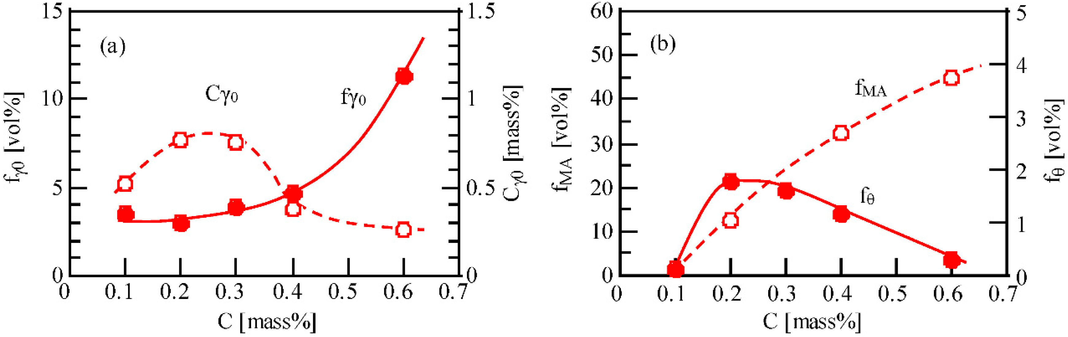
High carbon content increases the volume fractions of retained austenite and MA-like phase in (0.1–0.6)%C–1.5%Si–1.5%Mn TM steels with different carbon content (Figure 4). Higher carbon concentration of retained austenite can be obtained in the steels containing 0.2%C and 0.3%C [13,16]. The carbon concentration of retained austenite in 0.6%C steel is so much lower than the desired carbon content. This contradictory result may be due to large transformation strain of narrow lath-martensite. Microalloying of Cr, Mo, Ni and Mn also increases the volume fractions of retained austenite, MA-like phase and carbide, whereas decreases the carbon concentration of retained austenite [14,36].
Sometimes, the steel subjected to isothermal transforming at temperatures between martensite-start temperature (MS) and Mf after austenitization is also regarded as TM steel because of similar microstructure [11] and mechanical properties [16], although the microstructure consists of soft α′-martensite/bainitic ferrite matrix and a larger amount of retained austenite than that of TM steel [11]. In this case, soft α′-martensite fraction can be estimated by using the empirical equation proposed by Koistinen and Marburger [66]. This multi-step heat-treatment resembles one-step Q&P process at temperatures between MS and Mf.
2.2. Tensile Properties
When isothermal transformation treatment is carried out at temperatures below Mf in 0.2%C–1.5%Si–1.5%Mn–1.0%Cr–0.05%Nb TM steel, the tensile strength decreases and the total elongation increases with increasing isothermal transformation temperature [16]. In (0.1–0.6)%C–1.5%Si–1.5%Mn TM steels [13,16], the yield stress (or 0.2% offset proof stress) and tensile strength increase with increasing carbon content except for 0.6%C steel which fractures at an early stage (Figure 5). On the other hand, total and uniform elongations decrease with increasing carbon content. Resultantly, 0.4%C steel possesses the highest combination of tensile strength and total elongation (TS × TEl = 23 GPa %). The notch-tensile strength tends to increase with increasing carbon content in the same way as tensile strength. TM steels with carbon content of 0.2% to 0.4% exhibit higher notch-strength ratio than 0.1%C steel due to high TRIP effect of the retained austenite. The high notch-strength ratios are the same as those of quenched and tempered JIS-SCM420, 435 and 440 steels (Cr-Mo steels with different carbon content) [13]. Additions of Cr, Mo, Ni and Mn to 0.2%C–1.5%Si–1.5%Mn TM steel increase the yield stress and tensile strength, but decrease the elongations. Optimum combination of tensile properties can be obtained for 1.0%Cr bearing TM steel [14,17].
Sugimoto et al. [17] proposed that high combination of tensile strength and total elongation of TM steel is associated with the following characteristic microstructures;
- (1)
- a soft wide lath-martensite matrix with only a little carbide and diluted carbon concentration which improves the ductility,
- (2)
- a large quantity of finely dispersed MA-like phase which produces a large mean internal stress resulting from a difference in flow stress between a soft wide-lath martensite and a hard MA-like phase,
- (3)
- a metastable retained austenite of 2–5 vol %, which increases hard strain-induced martensite fraction and plastically relaxes the localized stress concentration on strain-induced transformation.
2.3. Impact Toughness
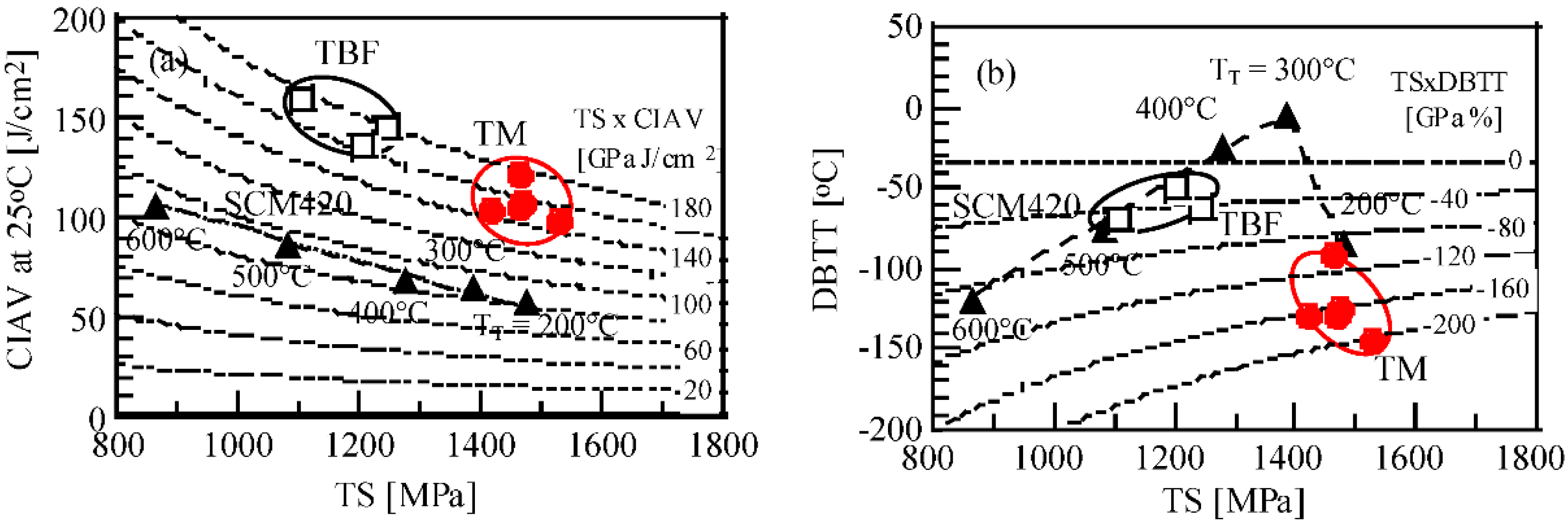
It can be seen that when 1%Cr, 1%Cr–0.2%Mo, or 1%Cr–0.2%Mo–1.5%Ni is added to the base steel with a chemical composition of 0.2%C, 1.5%Si, 1.5%Mn and 0.05%Nb, the TM steels exhibit high V-notched Charpy impact absorbed values at 25°C ranging between 100 to 125 J/cm2, and low ductile-brittle transition temperatures (corresponding to 50% ductile fracture appearance on Charpy impact tests) ranging from −150 to −130 °C (Figure 6) [14,19]. Moreover, the steels also possess the tensile strengths of around 1.4 to 1.5 GPa. The impact properties are far superior to those of the conventional low alloy martensitic steel (SCM 420 steel), in the same way as TBF and tempered Q&P [31] steels. In addition, the transition temperatures are considerably lowered as compared to TBF, tempered Q&P [31] and SCM420 steel. From the load–displacement curves obtained by impact testing, it is found that high impact values of TM steels are mainly caused by the high crack propagation energy [14]. Partitioning at 300 °C for 1000 s after isothermal transforming increases further impact values [12,14].
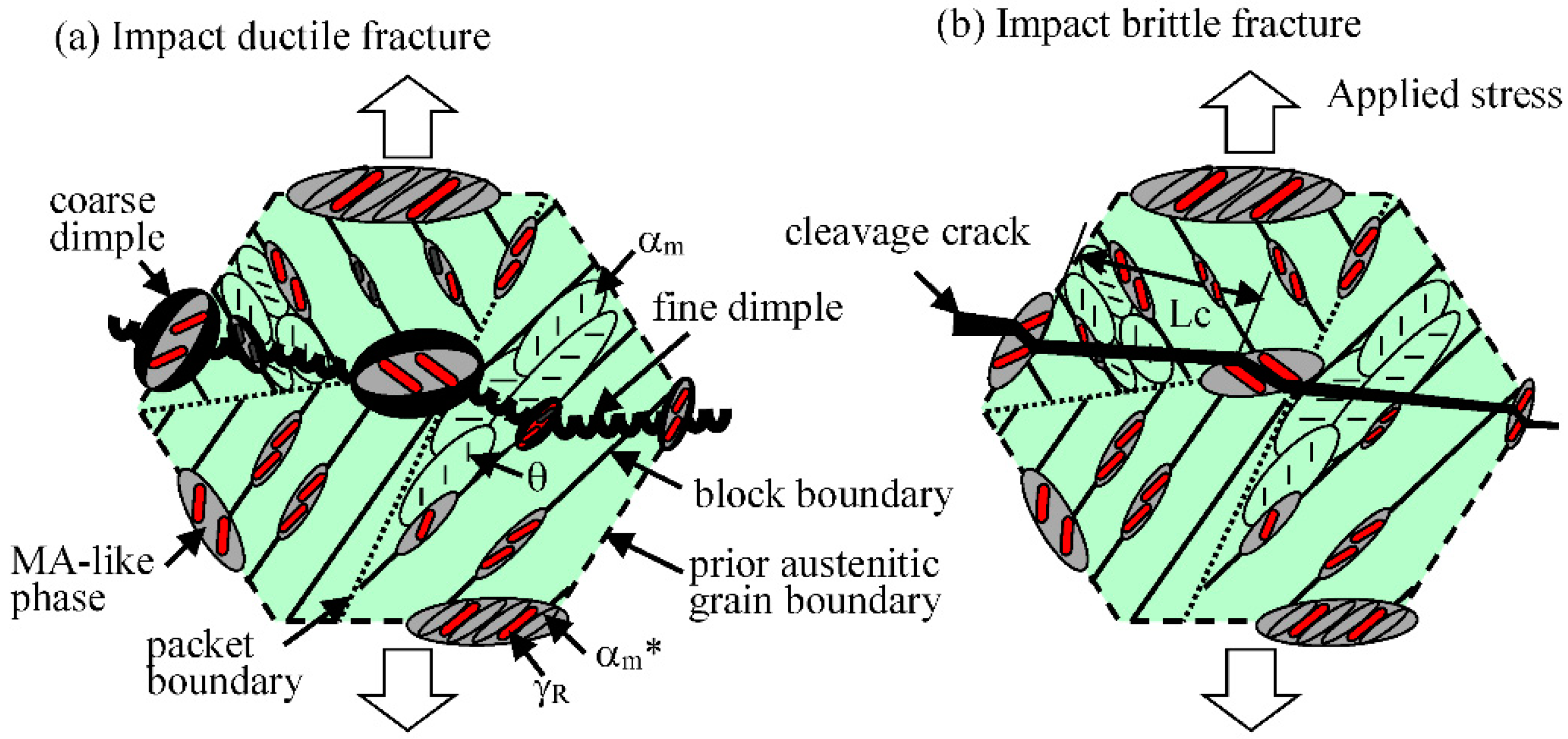
Figure 7 depicts the fracture mechanism of ductile and brittle impact fractures of TM steel [14]. In a case of ductile impact fracture, MA-like phases play an important role in suppressing the void initiation and promoting the preferential void growth at the MA-like phase/matrix interface (Figure 7a). In a case of brittle impact fracture, on the other hand, the MA-like phases also inhibit the initiation of cleavage cracking, as shown in Figure 7b, because they reduce the facet size of cleavage crack and the strain-induced transformation of the retained austenite relaxes plastically the localized stress concentration. With this, the superior impact properties of TM steel are believed to be caused by the characteristic microstructure of (1) to (3) mentioned in the last of Section 2.2.
2.4. Fatigue Properties
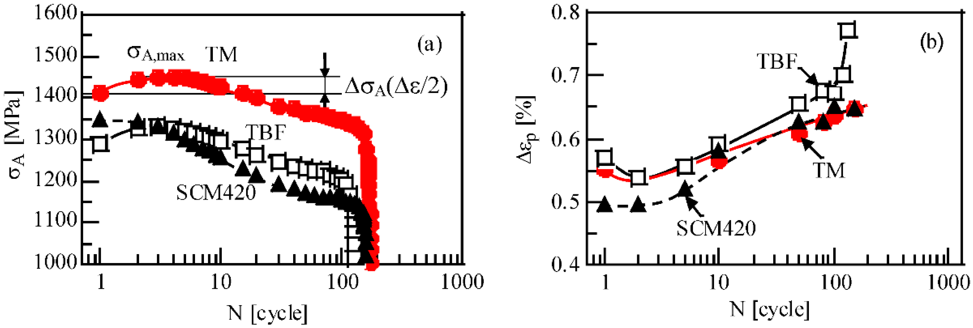
TM steel exhibits large fatigue hardening with subsequent softening in the same way as TBF steel (Figure 8a) [2,3,8,20], although commercial low alloy martensitic steel (SCM420 steel) softens during the cyclic deformation. Regardless of the high stress amplitude, a longer failure time and a larger plastic strain amplitude than those of SCM420 steel are also observed in the TM steel (Figure 8b), although the plastic strain is smaller than that of TBF steel. This cyclic hardening is mainly caused by “mean internal stress hardening” and “transformation hardening” [20] which result from the characteristic microstructures such as (1), (2) and (3) mentioned in the last of Section 2.2.
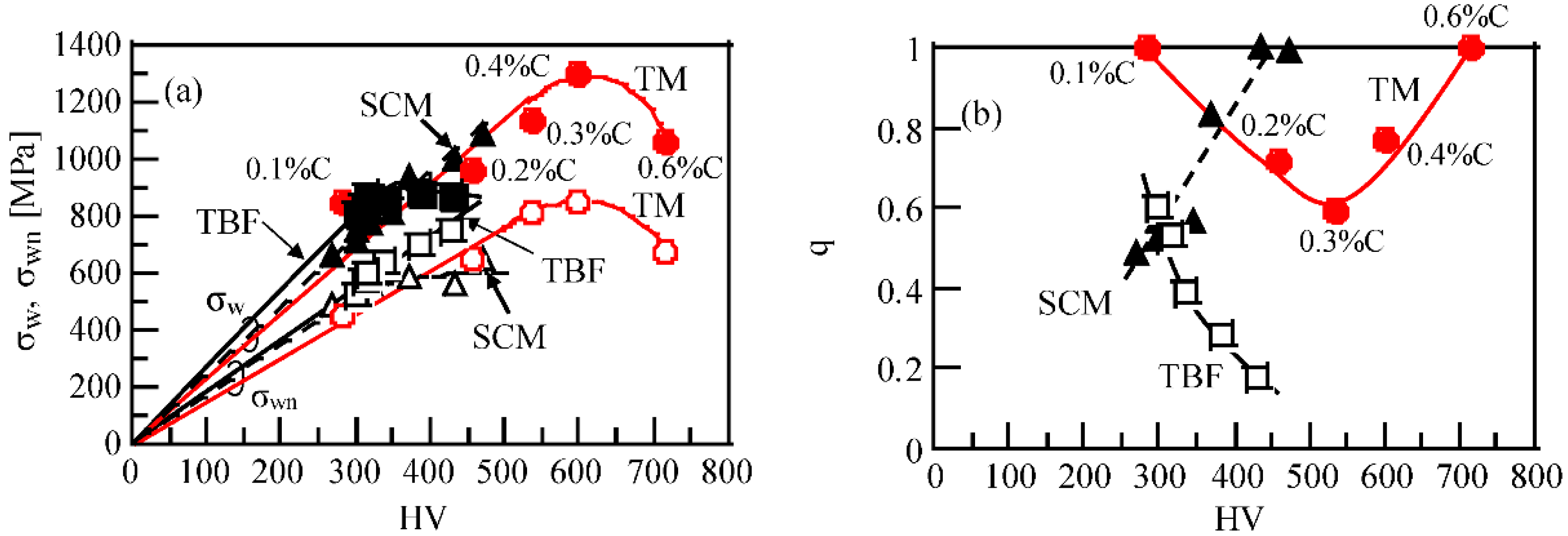
Figure 9 shows fatigue limits of smooth and notched specimens of (0.1–0.6)%C–1.5%Si–1.5%Mn TM steels with different carbon content [13,19] and the “notch-sensitivity factor q” [67] defined by the following equation,
where Kf and Kt are fatigue-notch factor (= σw/σwn; σw, σwn: fatigue limits of smooth and notched specimens, respectively) and stress concentration factor (1.9 in this study), respectively. Both fatigue limits of smooth and notched specimens increase with increasing carbon content in steels between 0.1%C and 0.4%C. The notch-sensitivity factor is the minimum in 0.3%C steel. Notched fatigue limits of the steels containing 0.2%C to 0.4%C are higher than those of SCM420, 435 and 440 steels with different carbon content. The notch-sensitivity factors of the TM steels are lower than those of SCM420, 435 and 440 steels. However, TBF steels possess relatively higher notch fatigue limits and far lower notch sensitivity factor than TM steels [7]. Similar tendency is also reported for fatigue limits in Q&P steels [24,27,28,41].
q = (Kf − 1)/(Kt − 1)
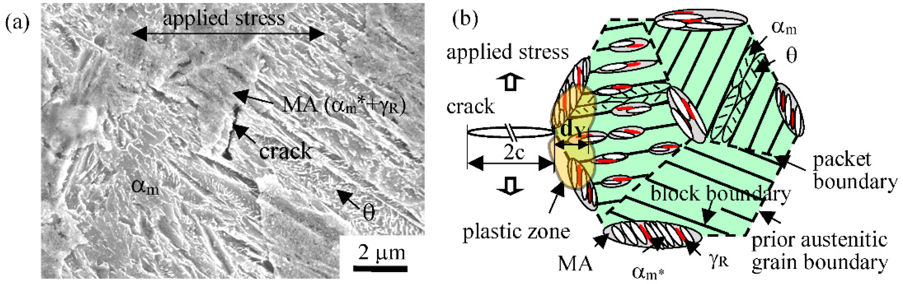
In general, fatigue limits of smooth and notched specimens are principally controlled by fatigue crack initiation and propagation stages, respectively. Figure 10a shows a SEM image illustrating a fatigue crack initiated on the surface of a notched specimen of TM steel [13]. According to Knott [68], the plastic zone size dY of crack tip under plane strain condition (Figure 10b) can be estimated from the following equation:
where YS is the yield stress, and K is the stress intensity factor defined as σ(πc)1/2, σ is the applied stress, and c is the crack length. From Figure 10a, it appears that the fatigue crack initiates in the wide lath martensite structure and is stopped at the MA-like phase [13]. In the 0.4%C steel, the plastic zone size is estimated to be about 2.0 μm if the fatigue crack length at the first stage is 2c = 30 μm, equivalent to the prior austenitic grain size, and the applied stress is corresponding to the fatigue limit. The plastic zone always includes some retained austenite particles in MA-like phase (see Figure 10b) because the interparticle path of MA-like phase is 0.5 to 2.0 μm (Figure 2b). Therefore, the plastic relaxation by the strain-induced transformation of retained austenite can be expected to take place always in the plastic zone during fatigue deformation. In conclusion, the high notch fatigue limits of TM steels can be considered to be principally caused by an increase in volume fraction of hard phase, plastic relaxation and crack closure via the strain-induced martensite transformation of metastable retained austenite, as well as a very small amount of carbide. Tomita et al. [41] also reports the similar improving mechanism for fatigue strength in 0.6%C–1.5%Si–0.8%Mn steel.
dY = K2/(6πYS2)
It is very difficult to compare the fatigue limits of TM steels with other AHSSs because fatigue tests are not conducted under the same fatigue mode and stress ratio. However, from comparison of several references [1,4,6,7,9,27,28,41,42,44,45,46,47,48], we can conclude that TM steels possess the high fatigue limits compared to the conventional quenched and tempered martensitic steels, in the same way as several AHSSs such as TBF steels [1,4,6,7,9], Q&P steels [27,28] and nanostructured bainitic steels [41,42,44,45,46,47,48,49].
3. Heat-Treated and Subsequently Fine-Particle Peened TM Steels
3.1. Surface-Hardened Layer Properties
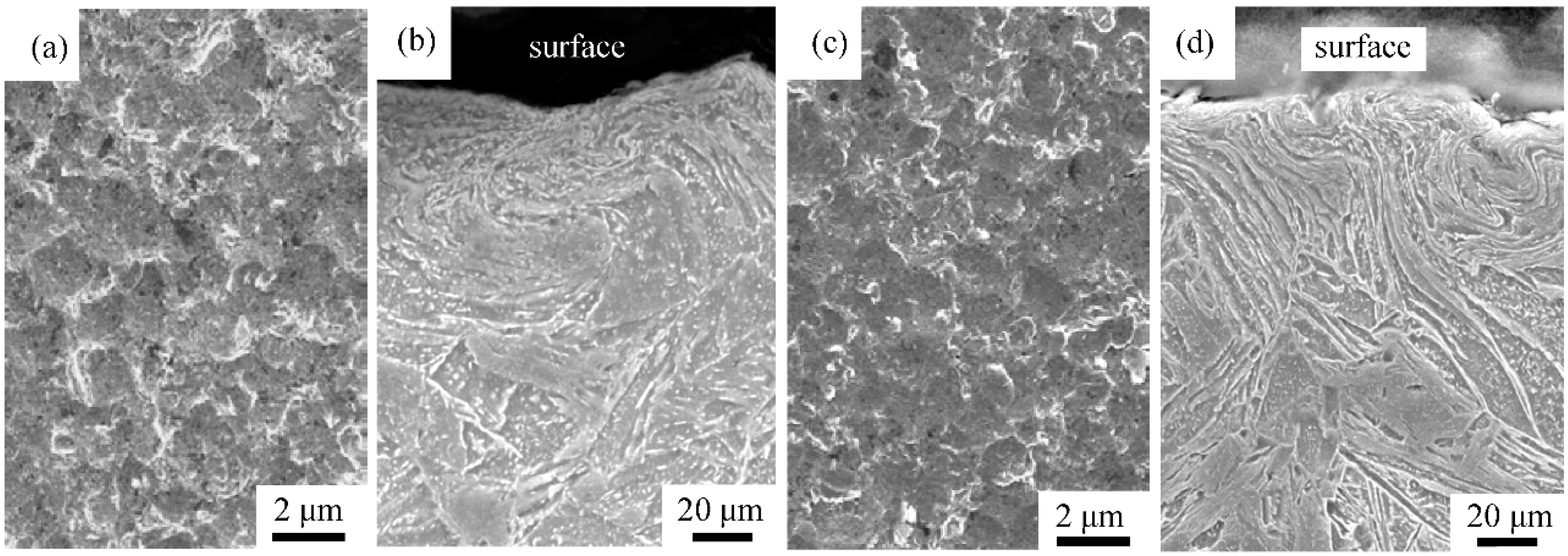
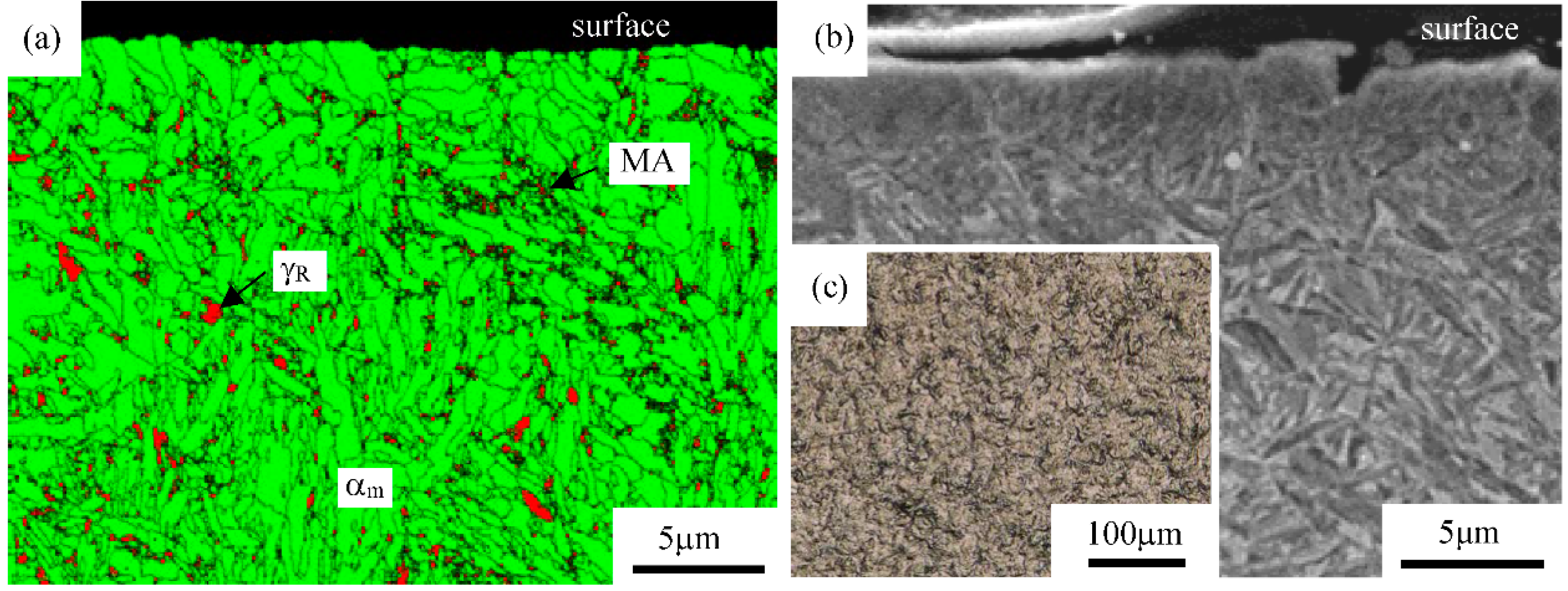
When heat-treated 0.2%C–1.5%Si–1.5%Mn–1.0%Cr TM and JIS-SNCM420 steels (0.2%C–0.2%Si–0.5%Mn–0.6%Cr–0.2%Mo–1.7%Ni, quenched and tempered at 200 °C for 3600 s) are subjected to fine-particle peening under arc-height of 0.104 mm (N) at room temperature [62], the microstructures just below the surface are considerably refined and severely deformed without white layer (a nanosized or amorphous structure) [69], in the same way as TBF steel [60,61] (Figure 11b,d). In this case, arc-height of fine-particle peening is quantified using Almen strip of N type and the coverage is 300%. The maximum roughness height (Rz, JIS B0601:2001) on the surface of both steels is less than 4 μm because of the use of the small shot particles (steel ball of 70 μm diameter) (Figure 11a,c).
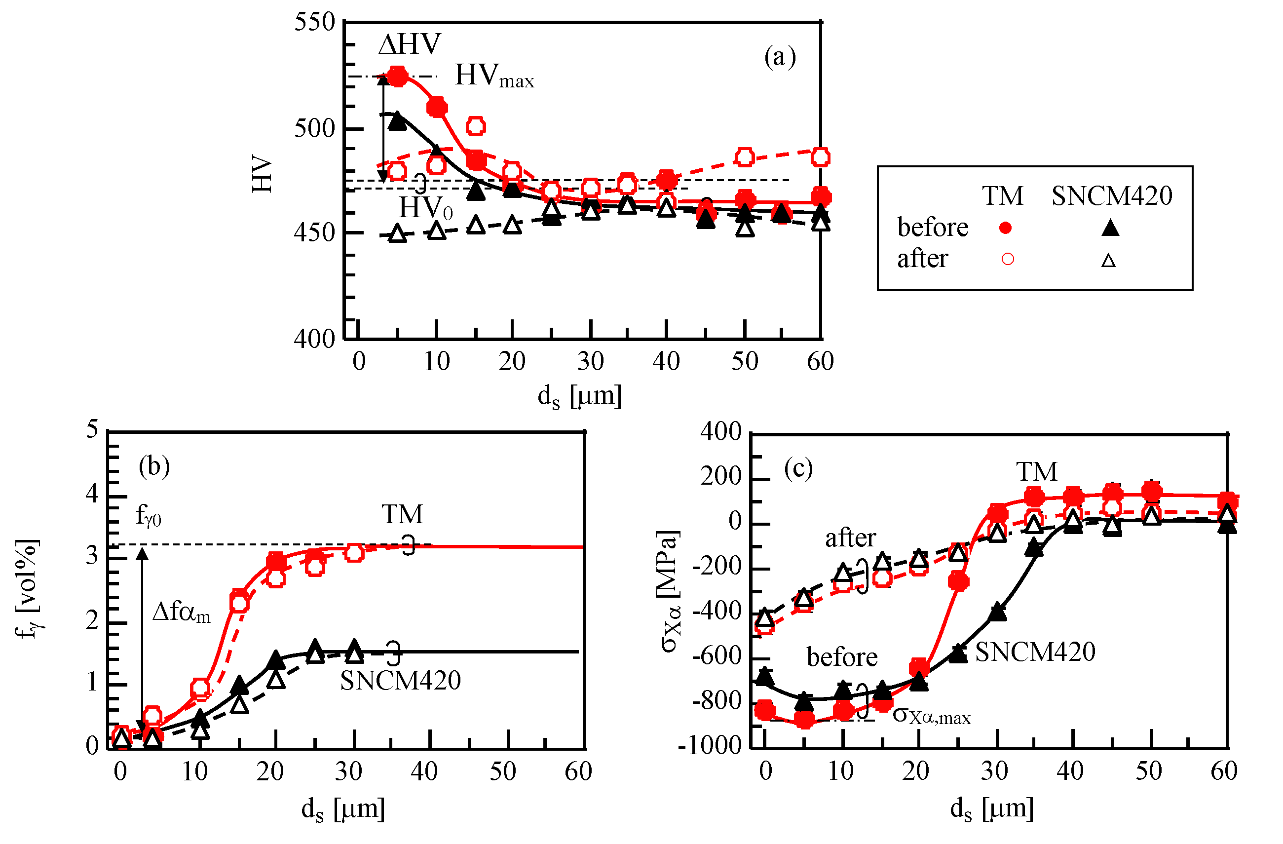
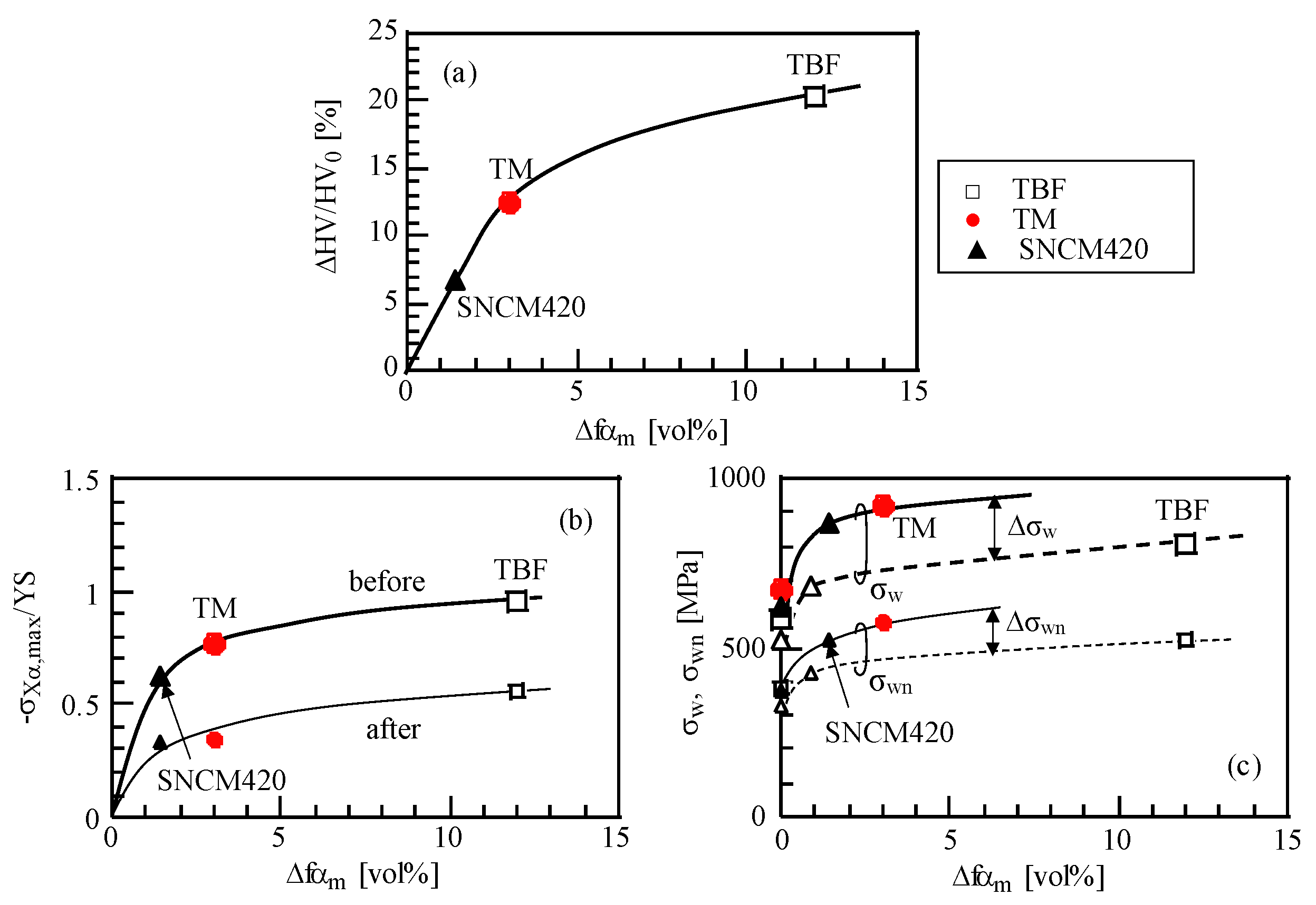
The distributions of Vickers hardness, volume fraction of untransformed retained austenite, and X-ray residual stress of the α(bcc) phase in the surface-hardened layer of the TM and SNCM420 steel specimens are shown in Figure 12 [62]. The depth of the surface-hardened layer before fatigue testing is approximately 20 μm in both steels; the maximum Vickers hardness increment (ΔHV, see Figure 12a) of the TM steel is larger than that of the SNCM420 steel. Most of the retained austenite transforms to martensite near the surface (Figure 12b). The ratio of the ΔHV to HV0 (initial Vickers hardness, see Figure 12a) of TM steel increases with increasing volume fraction of strain-induced martensite (Δfαm), in the same manner as that of the TBF steel (Figure 13a) [61]. High compressive residual stresses occur in the α(bcc) phase of both steels before fatigue testing (Figure 12c). The compressive residual stress of the TM steel is larger than that of the SNCM420 steel. Maximum compressive residual stresses before fatigue are obtained at a depth of approximately 5–10 μm from the surface in both steels.
The maximum Vickers hardness and maximum compressive residual stress increase with increasing Δfαm (Figure 13a,b). This indicates that the differences in Vickers hardness and compressive residual stress between both steels result from the differences in the Δfαm. The difference in the compressive residual stress is also associated with the expansion strain that occurs on the strain-induced martensite transformation.
After fatigue tests at the stress amplitude corresponding to fatigue limit, the surface-hardened layer is considerably softened in both steels (Figure 12a), with a slight decrease in the retained austenite fraction (Figure 12b). In particular, the Vickers hardness in the surface-hardened layer of SNCM420 steel is much lower than the original Vickers hardness. This behavior resembles cyclic softening of Figure 8a. It is noteworthy that the Vickers hardness of the TM steel increases even interior of the surface-hardened layer after fatigue deformation. Significant decreases in the compressive residual stress occur in both steels after fatigue test, although the compressive residual stress of the TM steel was slightly higher than that of SNCM420 steel (Figure 12c).
3.2. Fatigue Strength
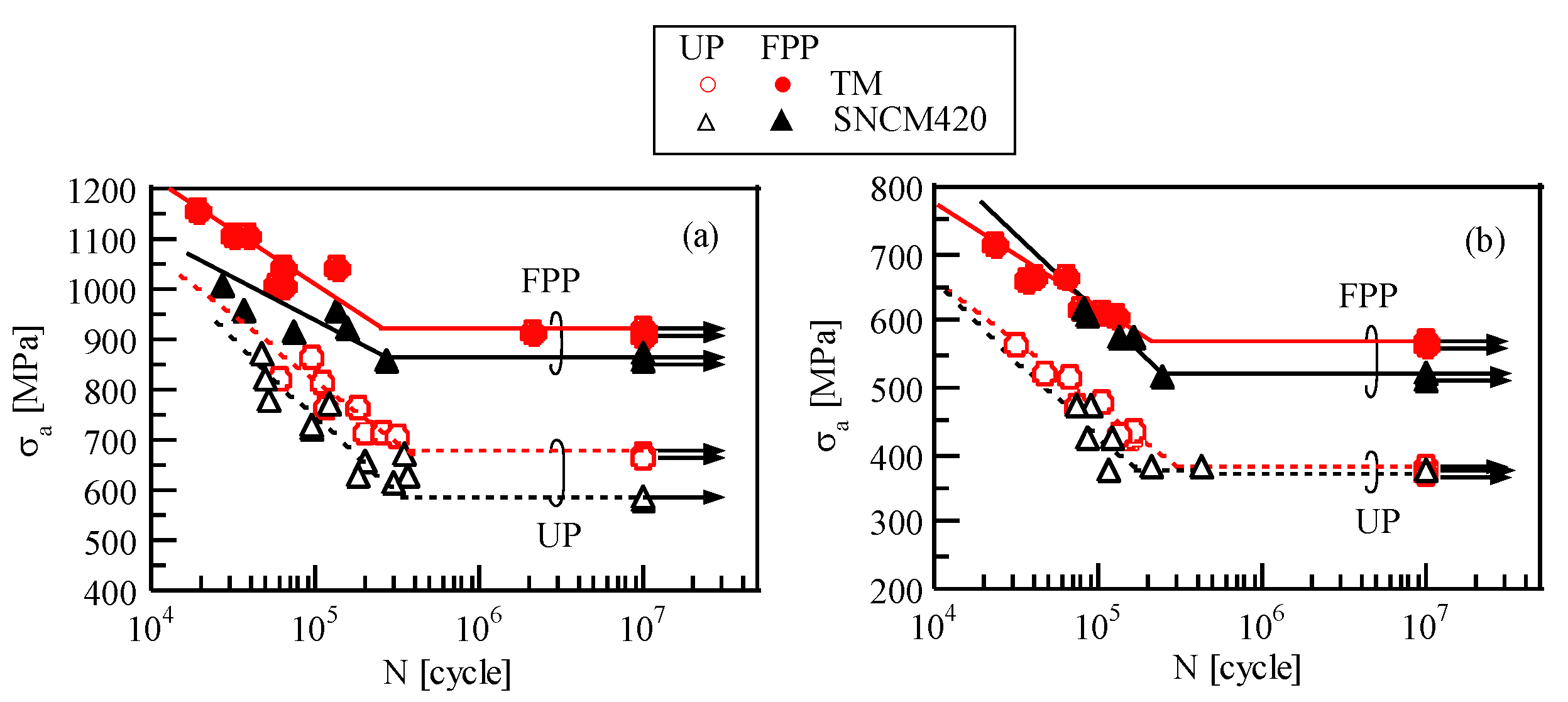
Heat-treated TM steel subjected to fine-particle peening under arc-height of 0.104 mm (N) achieves higher fatigue limits than SNCM420 steel, especially for the notched specimen (Figure 14). The TM steel also exhibits lower notch sensitivity factor q than the SNCM420 steel, although the q value for unpeened TM steel is higher than that for unpeened SNCM420 steel. It is considered that the fatigue limits of smooth and notched specimens in both steels are apparently enhanced by Δfαm, because the fatigue limits increase with increasing Δfαm (Figure 13c) [62]. In Figure 13c, fatigue limits of SNCM420 steel tempered at 430 °C are added for the purpose of reference.
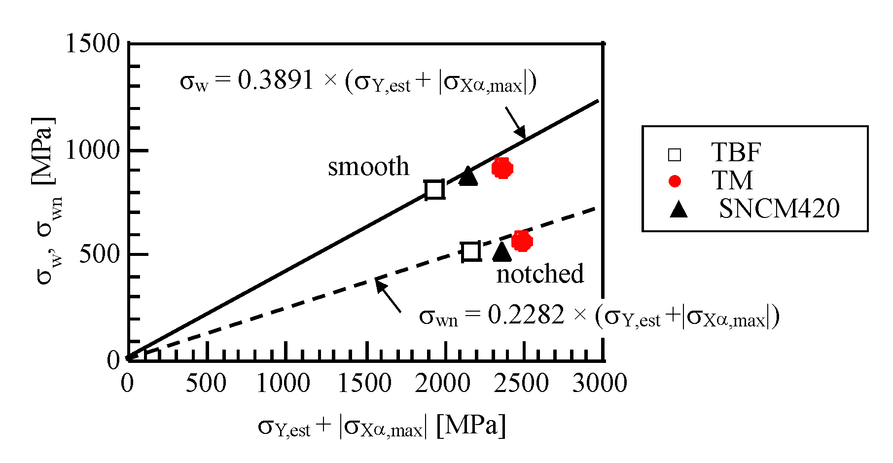
Matsui et al. [55] reported that the sum of estimated yield stress (σY,est) and the absolute value of maximum compressive residual stress of α(bcc) phase (|σXα,max|) is related to the fatigue limit in JIS-SCM822H steel (0.22%C–0.27%Si–0.74%Mn–0.17%Cu–0.06%Ni–1.09%Cr–0.36%Mo) subjected to shot peening under arc-heights of 0.30 mm (N), 0.55 mm (A) and 0.25 mm (C) after gas-carburizing, as follows:
σw = 0.3891 × (σY,est + |σXα,max|).
The value of σY,est can be estimated from HVmax by:
where YS/TS is the yield ratio (assumed by Matsui et al. [55] to be 0.95).
σY,est = (HVmax/3) × 9.80665 × (YS/TS),
The relationships between fatigue limits of smooth and notched specimens (σw and σwn) and σY,est +|σXα,max| for the TM and SNCM420 steels are shown in Figure 15 [62]. The σws of the TM and SNCM420 steels exhibit the same relationship as those by Matsui et al. [55], despite no carburizing. For a case of notched specimen of both steels, the following empirical equation is found:
σwn = 0.2282 × (σY,est + |σXα,max|).
4. Vacuum-Carburized and Subsequently Fine-Particle Peened TM Steels
4.1. Surface-Hardened Layer Properties
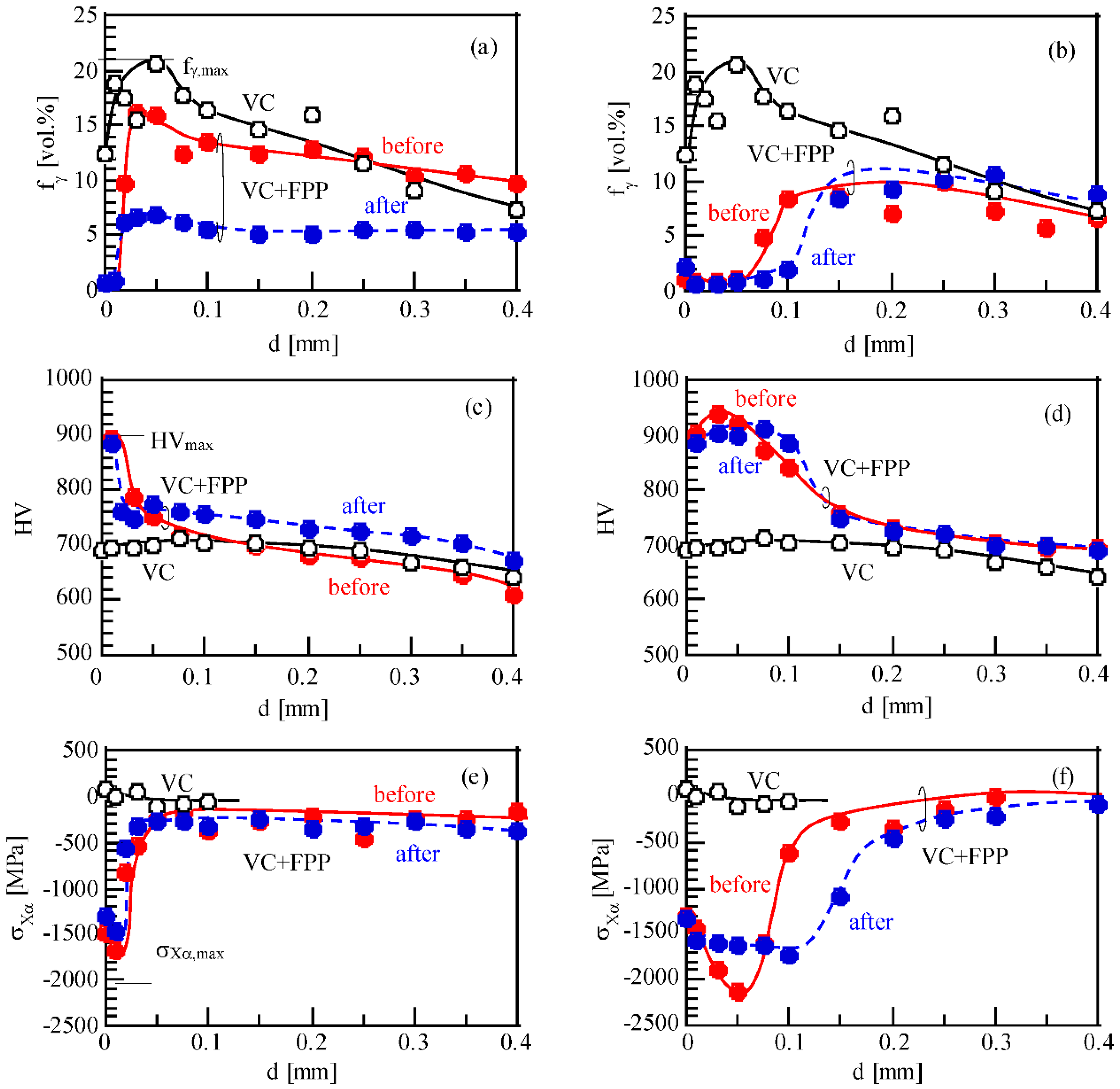
The surface hardened layer of 0.2%C–1.5%Si–1.5%Mn–1.0%Cr–0.2%Mo TM steel subjected to vacuum carburization under carbon potential of 0.8 mass% contains a large amount of retained austenite and a small amount of the MA-like phase, although coarsened microstructure appears near the surface (Figure 16a) [63]. The retained austenite fraction achieves to the maximum value (20.5 vol %) at a depth of 50 μm (Figure 17a). Two types of retained austenite, i.e., an island type in the matrix and a filmy type in the MA-like phase, appear in the steels (Figure 16a). A majority of the MA-like phase seems to be clustered along the prior austenitic, packet, and block boundaries. Vickers hardness of the as-vacuum-carburized TM steel is 713 at maximum (Figure 17c) and residual stress of α(bcc) phase is about −100 MPa (Figure 17e).
After fine-particle peening, maximum roughness height of vacuum-carburized TM steel increases with incresing arc-height (Figure 18b), although the surface roughness is nearly the same under arc-heights lower than 0.21 mm (N). The typical surface image is shown in Figure 16c. White layer [69], which plays an important role in the fatigue strength and wear resistance is formed on the surface of the vacuum-carburized TM steel subjected to fine-particle peening under arc-heights higher than 0.41 mm (N). A distinct white layer is not formed on the surface in case of arc-heights lower than 0.21 mm (N) (Figure 16b). In the vacuum-carburized TM steel subjected to fine-particle peening under arc-height lower than 0.21 mm (N), the maximum retained austenite fraction is obtained at a depth of 50 μm (Figure 17a). The maximum Vickers hardness and the maximum compressive residual stress are attained at the depths of 10–50 μm. It is noteworthy that the Vickers hardness and compressive residual stress attain to the maximum values on surface or at near surface, as well as a large amount of untransformed retained austenite, when fine-particle peening is conducted under arc-height of 0.104 and 0.21 mm (N) (Figure 17c,e). The depths referring to their maximum values increase with increasing arc-height for the fine-particle peening (Figure 17b,d,f). In a case of higher arc-height, a larger amount of the retained austenite transforms to martensite (Figure 17b).
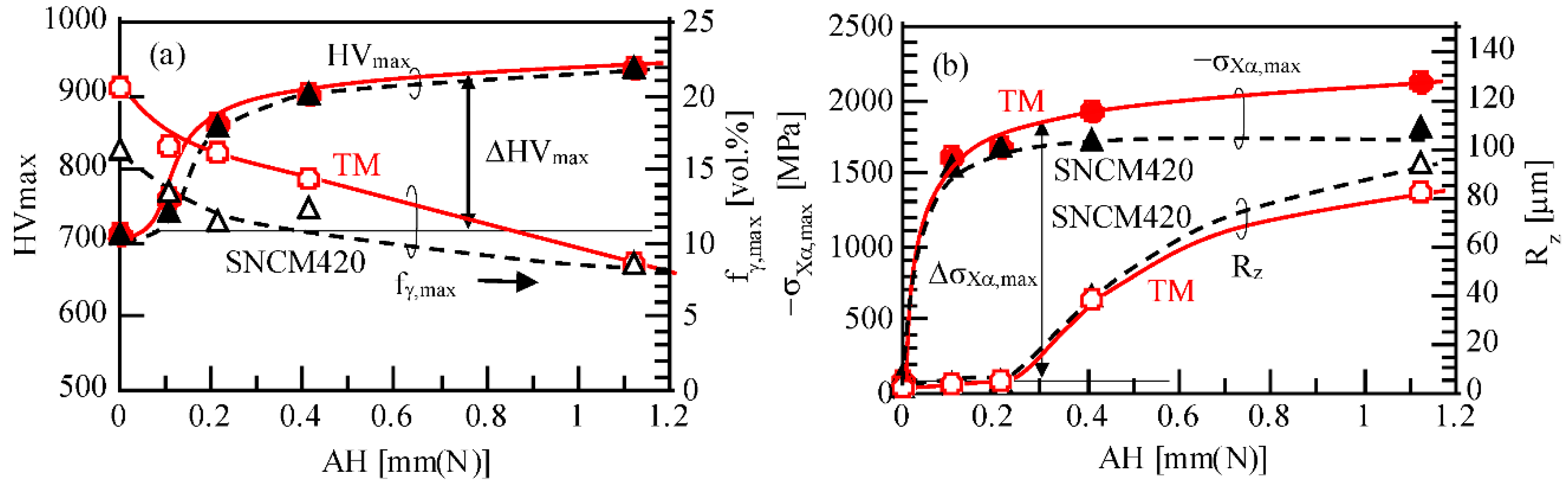
In vacuum-carburized TM and SNCM420 steels, the maximum volume fraction of retained austenite decreases with increasing arc-height (Figure 18a). On the other hand, the maximum Vickers hardness, the maximum residual stress and the maximum roughness height increase with increasing arc-height (Figure 18). The TM steel exhibits higher retained austenite fraction and compressive residual stress compared with SNCM420 steel, although the maximum Vickers hardness of both steels is almost the same. According to Sugimoto et al. [63], the maximum Vickers hardness and the maximum residual stress are mainly developed by severe plastic deformation, with a small contribution of the strain-induced martensitic transformation of the retained austenite.
4.2. Fatigue Properties
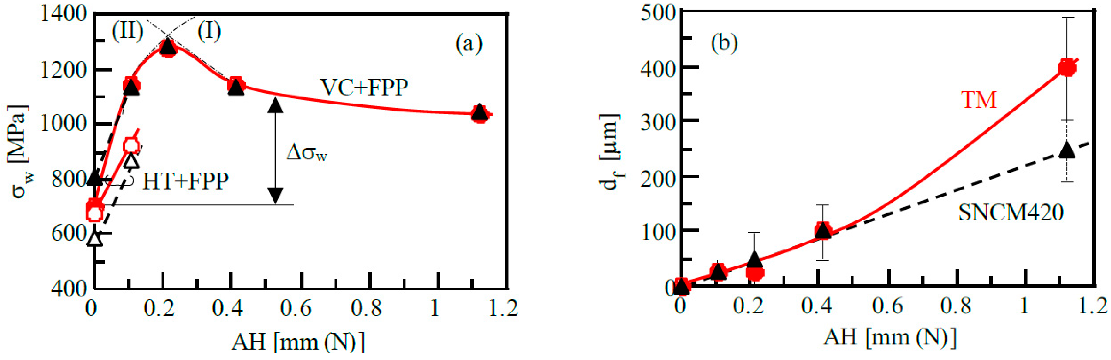
When vacuum-carburized TM and SNCM420 steels were subjected to fine-particle peening under arc-height of 0.21 mm (N), the fatigue limits of both steels exhibit the maximum values in an arc-height range of 0.104 to 1.22 mm (N) (Figure 19a) [64]. Moreover, the values of fatigue limit of both steels are similar, except for the fatigue limits of the vacuum-carburized steels. Kato et al. [53] also reported that the same arc-height achieved the highest fatigue limit in gas-carburized SCM822H steel (0.20%C–0.20%Si–0.75%Mn–0.15%Cu–0.10%Ni–1.10%Cr–0.15%Mo). The maximum increment in the fatigue limit (Δσw in Figure 19a) and the percentage increase of vacuum-carburized TM steel due to fine-particle peening are 574 MPa and 82% at maximum, respectively. By the comparison of the fatigue limits with those [62] of heat-treated TM steels subjected to fine-particle peening under arc-height of 0.104 mm (N), the increase in the fatigue limit (Δσw = 440 MPa) is greater than that (Δσw = 244 MPa) of heat-treated steels (Figure19a). The increase in the fatigue limit is greater than those of gas-carburized martensitic steel subjected to shot peening or fine particle peening [57]. The optimum arc-height value for fatigue limit may vary if fine-particle peening is conducted under different shot material, angle of attack, velocity, etc. According to Sugimoto et al. [65], vacuum carburization followed by fine-particle peening increases notch sensitivity factor for fatigue because only few increase in the notch fatigue limit is obtained compared to that of smooth specimen.
During fatigue deformation, a large amount of untransformed retained austenite transforms to martensite in vacuum-carburized TM steel subjected to fine-particle peening under low arc-height (Figure 17a). According to study [62] using heat-treated TM steel (containing retained austenite fraction of 3.1 vol %) subjected to fine-particle peening under the arc-height of 0.104 mm (N), the Vickers hardness and the residual stress in the surface-hardened layer considerably decreased during a fatigue test at a stress amplitude corresponding to the fatigue limit. In this study, however, their declines are relatively slight and the Vickers hardness at a depth of more than 50 μm increases during fatigue deformation in vacuum-carburized TM steel subjected to fine particle peening under arc-height of 0.21 mm (N) (Figure 17c). The strain-induced martensite fraction during fatigue deformation of vacuum-carburized and fine-particle peened TM steel is far higher than that of heat-treated TM steel subjected to fine particle peening (Figure 17a). Therefore, this result indicates that the strain-induced martensite transformation of a large amount of untransformed retained austenite during fatigue deformation compensates large decreases in Vickers hardness and compressive residual stress and highly maintains the properties during fatigue deformation. Resultantly, the small declines of the Vickers hardness and compressive residual stress during fatigue deformation is considered to increase considerably the fatigue limit.
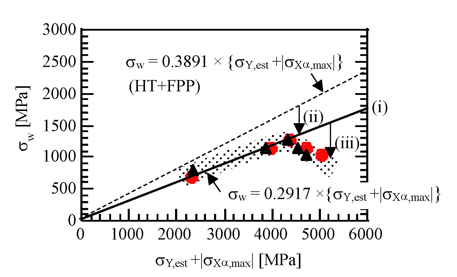
In Figure 20, the fatigue limits of vacuum-carburized TM steel subjected to fine-particle peening under the arc-height of 0.104 and 0.21 mm (N) reduce by decline (ii), compared to those of heat-treated TM steel although they linearly increase with increasing σY,est + |σXα,max| (line (i)). Meanwhile, the fatigue limits under arc-height of 0.41 and 1.12 mm (N) shift down by decline (iii), despite higher maximum Vickers hardness and maximum compressive residual stress in the surface-hardened layer than those under lower arc-height. Sugimoto et al. [64] explain the declines (ii) and (iii) as follows.
The declines in fatigue limits of vacuum-carburized TM steel are related to the depth of fish-eye crack from surface because most of the fatigue failure occurrs by fish-eye cracks (Figure 21), different from that of heat-treated TM steel [62]. The fish-eye crack depth increases with increasing arc-height of fine-particle peening (Figure 19b and Figure 21). Therefore, decline (ii) in fatigue limit is considered to be caused by fish eye fracture. Decline (iii) in fatigue limits is associated with deep fish-eye fracture and a small amount of strain-induced martensite transformation during fatigue deformation (Figure 17b). In this case, superior surface-hardened layer properties and a white layer formed by fine particle peening under the arc-height higher than 0.41 mm (N) hardly contribute to increase the fatigue limit (Figure 21b), although a little strain-induced martensite plays a role in slight plastic relaxation of the localized stress concentration [70].
5. Conclusions
The as-heat-treated TM steels possessed excellent impact toughness (high Charpy impact absorbed value and low ductile-brittle transition temperature) and high fatigue strength (large cyclic softening, high fatigue limit and low notch-sensitivity). When the steels are subjected to fine-particle peening after heat-treatment, the fatigue limits of smooth and notched specimens increased considerably, accompanied with low notch sensitivity. Vacuum carburization and subsequent fine-particle peening increased further the fatigue strength of the steels, except notch fatigue limit. The increased fatigue limits were principally associated with high Vickers hardness and compressive residual stress just below the surface, resulting from the severe plastic deformation and the strain-induced martensitic transformation of metastable retained austenite, as well as low surface roughness and fatigue crack initiation depth.
Further increases in the mechanical properties are possible by hot-forging prior to case-hardening, which brings on an increase in retained austenite fraction and a refined microstructure. Resultantly, the hot-forging is expected to improve the toughness and fatigue strength [12,15,18], in the same way as TBF steels [71,72,73]. The use of C, Cr and Mo bearing TM steels makes easy to manufacture the hot-forged parts as drivetrains, Diesel engine common rail systems, and others [40] and resultantly achieve the lightweight and low fuel consumption, instead of conventional high-strength low alloy steels. It is greatly hoped that many researchers interest in the hot-forging of TM steel and investigate the mechanical properties, such as fatigue strength, toughness and wear property of the case-hardening hot-forging products.
Acknowledgments
This study was supported by a Grant-in-Aid for Scientific Research (B), the Ministry of Education, Science, Sports and Culture, Japan (No. 2013-25289262).
Conflicts of Interest
The authors declare no conflict of interest.
References
- Sugimoto, K.; Kobayashi, M.; Inoue, K.; Sun, X.; Soshiroda, T. Fatigue strength of TRIP-aided bainitic sheet steels. Tetsu-to-Hagane 1998, 52, 559–565. [Google Scholar] [CrossRef]
- Sugimoto, K.; Kobayashi, M.; Inoue, K.; Masuda, S. Fatigue-hardening behavior of TRIP-aided bainitic steels. Tetsu-to-Hagane 1999, 85, 856–862. [Google Scholar] [CrossRef]
- Sugimoto, K.; Song, S.; Inoue, K.; Kobayashi, M.; Masuda, S. Effect of prestraining on low cycle fatigue properties of low alloy TRIP steels. J. Soc. Mater. Sci. Jpn. 2001, 50, 657–664. [Google Scholar] [CrossRef]
- Song, S.; Sugimoto, K.; Kandaka, S.; Futamura, A.; Kobayashi, M.; Masuda, S. Effects of prestraining on high cycle fatigue strength of high strength low alloy TRIP steels. J. Soc. Mater. Sci. Jpn. 2001, 50, 1091–1097. [Google Scholar] [CrossRef]
- Sugimoto, K. Fracture strength and toughness of ultrahigh-strength TRIP aided steels. Mater. Sci. Technol. 2009, 25, 1108–1117. [Google Scholar] [CrossRef]
- Sugimoto, K.; Yoshikawa, N. Advanced high-strength TRIP-aided steels for ultra high pressure DI-diesel engine common rail. In Proceedings of the 3rd International Conference on Stainless Steel in Cars and Trucks (SCT2011), Stuttgart, Germany, 5–9 June 2011; pp. 365–372. [Google Scholar]
- Yoshikawa, N.; Kobayashi, J.; Sugimoto, K. Notch fatigue properties of advanced TRIP-aided bainitic ferrite steels. Metall. Mater. Trans. A 2012, 43, 4129–4136. [Google Scholar] [CrossRef]
- Zhou, Q.; Qian, L.; Meng, J.; Zhao, L.; Zhang, F. Low-cycle fatigue behavior and microstructure evolution in a low carbon carbide-free bainitic steel. Mater. Des. 2015, 85, 487–496. [Google Scholar] [CrossRef]
- El-Din, H.N.; Showaib, E.A.; Zaafarani, N.; Refaiy, H. Structure-properties relationship in TRIP type bainitic ferrite steel austempered at different temperatures. Int. J. Mech. Mater. Eng. 2017, 12, 3. [Google Scholar] [CrossRef]
- Sugimoto, K.; Hojo, T.; Kobayashi, J. Critical assessment of TRIP-aided bainitic ferrite steels. Mater. Sci. Technol. 2017, 33, 2005–2007. [Google Scholar] [CrossRef]
- Kobayashi, J.; Song, S.; Sugimoto, K. Microstructure and retained austenite characteristics of ultrahigh-strength TRIP-aided martensitic steels. ISIJ Int. 2012, 52, 1124–1129. [Google Scholar] [CrossRef]
- Kobayashi, J.; Sugimoto, K.; Arai, G. Effects of hot-forging process on combination of strength and toughness in ultrahigh-strength TRIP-aided martensitic steels. Adv. Mater. Res. 2012, 409, 696–701. [Google Scholar] [CrossRef]
- Kobayashi, J.; Yoshikawa, N.; Sugimoto, K. Notch-fatigue strength of advanced TRIP-aided martensitic steels. ISIJ Int. 2013, 53, 1479–1486. [Google Scholar] [CrossRef]
- Kobayashi, J.; Ina, D.; Nakajima, Y.; Sugimot, K. Effects of microalloying on the impact toughness of ultrahigh-strength TRIP-aided martensitic steels. Metall. Mater. Trans. A 2013, 44, 5006–5017. [Google Scholar] [CrossRef]
- Sugimoto, K.; Kobayashi, J.; Hojo, T. Mechanical properties of TRIP-aided martensitic steels for hot-worked automotive drivetrain components. In Proceedings of the 4th International Conference on Steels in Cars and Trucks (SCT), Braunschweig, Germany, 15–19 June 2014; pp. 21–28. [Google Scholar]
- Kobayashi, J.; Ina, D.; Futamura, A.; Sugimoto, K. Fracture toughness of an advanced ultrahigh-strength TRIP-aided steels. ISIJ Int. 2014, 54, 955–962. [Google Scholar] [CrossRef]
- Pham, D.V.; Kobayashi, J.; Sugimoto, K. Effects of microalloying on stretch-flangeability of ultrahigh-strength TRIP-aided martensitic steel sheet. ISIJ Int. 2014, 54, 1943–1951. [Google Scholar] [CrossRef]
- Hojo, T.; Kobayashi, J.; Kochi, T.; Sugimoto, K. Effects of thermomechanical processing on microstructure and shear properties of 22SiMnCrMoB TRIP-aided martensitic steel. Iron Steel Technol. Mag. 2015, 12, 102–110. [Google Scholar]
- Sugimoto, K.; Srivastava, A.K. Microstructure and mechanical properties of a TRIP-aided martensitic steel. Metall. Microstr. Anal. 2015, 4, 344–354. [Google Scholar] [CrossRef]
- Sugimoto, K.; Hojo, T. Fatigue hardening behavior of a 1.5 GPa Grade TRIP-aided martensitic steel. Metall. Mater. Trans. A 2016, 47, 5272–5279. [Google Scholar] [CrossRef]
- Zhao, P.; Cheng, C.; Gao, G.; Hui, W.; Misra, R.D.K.; Bai, B.; Weng, Y. The potential significance of microalloying with niobium in governing very high cycle fatigue behavior of bainit/martensite multiphase steels. Mater. Sci. Eng. A 2016, 650, 438–444. [Google Scholar] [CrossRef]
- Speer, J.G.; Matlock, D.K.; De Cooman, B.C.; Schroth, J.G. Carbon partitioning into austenite after martensite transformation. Acta Mater. 2003, 51, 2611–2622. [Google Scholar] [CrossRef]
- Speer, J.G.; De Moor, E.; Findley, K.O.; Matlock, D.K.; De Cooman, B.C.; Edmonds, D.V. Analysis of microstructure evolution in quenching and partitioning automotive sheet steel. Metall. Mater. Trans. A 2011, 42, 3591–3601. [Google Scholar] [CrossRef]
- Cerny, I.; Mikulova, D.; Sis, J.; Masek, B.; Jirkova, H.; Malina, J. Fatigue properties of a low alloy 42SiCr steel heat treated by quenching and partitioning process. Proc. Eng. 2011, 10, 3310–3315. [Google Scholar] [CrossRef]
- Toji, Y.; Matsuda, H.; Herbig, M.; Choi, P.; Raabe, D. Atomic-scale analysis of carbon partitioning between martensite and austenite by atom probe tomography and correlative transmission electron microscopy. Acta Mater. 2014, 65, 215–228. [Google Scholar] [CrossRef]
- Wu, R.; Li, W.; Zhou, S.; Zhong, S.; Wang, L.; Jin, X. Effect of retained austenite on the fracture toughness of quenching and partitioning (Q&P)-treated sheet steels. Metall. Mater. Trans. A 2014, 45, 1892–1902. [Google Scholar]
- De Diego-Calderon, I.; Rodriguez-Calvillo, A.; Lara, A.; Molina-Aldareguia, J.M.; Petrov, R.H.; De Knijf, D.; Sabirov, I. Effect of microstructure on fatigue behavior of advanced high strength steels produced by quenching and partitioning and the role of retained austenite. Mater. Sci. Eng. A 2015, 641, 215–224. [Google Scholar] [CrossRef]
- Zhao, P.; Zhang, B.; Cheng, C.; Misra, R.D.K.; Gao, G.; Bai, B.; Weng, Y. The significance of ultrafine film-like retained austenite in governing very high cycle fatigue behavior in an ultrahigh-strength MN–SI–Cr–C steel. Mater. Sci. Eng. A 2015, 645, 116–121. [Google Scholar] [CrossRef]
- Speer, J.G.; De Moor, E.; Clarke, A.J. Critical assessment 7: Quenching and partitioning. Mater. Sci. Technol. 2015, 31, 3–9. [Google Scholar] [CrossRef]
- Seo, E.J.; Cho, L.; Estrin, Y.; De Cooman, B.C. Microstructure-mechanical properties relationships for quenching and partitioning (Q&P) processed steel. Acta Mater. 2016, 113, 124–139. [Google Scholar]
- Gao, G.; An, B.; Zhang, H.; Guo, H.; Gui, X.; Bai, B. Concurrent enhancement of ductility and toughness in an ultrahigh strength lean alloy steel treated by bainite-based quenching-partitioning-tempering process. Mater. Sci. Eng. A 2017, 702, 104–112. [Google Scholar] [CrossRef]
- Miller, R.L. Ultrafine-grained microstructures and mechanical properties of alloy steels. Metall. Trans. 1972, 3, 905–912. [Google Scholar] [CrossRef]
- Furukawa, T. Dependence of strength-ductility characteristics on thermal history in low carbon 5 wt-%Mn steels. Mater. Sci. Technol. 1989, 5, 465–470. [Google Scholar] [CrossRef]
- Furukawa, T.; Huang, H.; Matsumura, O. Effects of carbon content on mechanical properties of 5% Mn steels exhibiting transformation induced plasticity. Mater. Sci. Technol. 1994, 10, 964–969. [Google Scholar] [CrossRef]
- Nakada, N.; Tsuchiyama, T.; Takaki, S.; Miyano, N. Temperature dependence of austenite nucleation behavior from lath martensite. ISIJ Int. 2011, 51, 299–304. [Google Scholar] [CrossRef]
- Sugimoto, K.; Tanino, H.; Kobayashi, J. Impact toughness of medium Mn transformation-induced plasticity-aided steels. Steel Res. Int. 2015, 86, 1151–1160. [Google Scholar] [CrossRef]
- Rana, R.; Gibbs, P.J.; De Moor, E.; Speer, J.G.; Matlock, D.K. A composite modeling analysis of the deformation behavior of medium manganese steels. Steel Res. Int. 2015, 86, 1139–1150. [Google Scholar] [CrossRef]
- Tsuchiyama, T.; Inoue, T.; Tobata, J.; Akama, D.; Takaki, S. Microstructure and mechanical properties of a medium manganese steel treated with interrupted quenching and intercritical annealing. Scr. Mater. 2016, 122, 36–39. [Google Scholar] [CrossRef]
- Qi, X.Y.; Du, L.X.; Hu, J.; Misra, R.D.K. High-cycle fatigue behavior of low-C medium-Mn high strength steel with austenite-martensite submicron-sized lath-like structure. Mater. Sci. Eng. A 2018, 718, 477–482. [Google Scholar] [CrossRef]
- Raedt, H.W.; Wilke, F.; Ernst, C.S. Light weight forging initiative phase II: Lightweight design potential for a light commercial vehicle. ATZ 2015, 118, 48–52. [Google Scholar]
- Tomita, Y.; Kijima, F.; Morioka, K. Modified austempering effect on bending fatigue properties of Fe-0.6C-1.5Si-0.8Mn steel. Z. Metallkd. 2000, 91, 43–46. [Google Scholar]
- Bhadeshia, H.K.D.H. Nanostructure bainite. Proc. R. Soc. Lond. A 2010, 466, 3–18. [Google Scholar] [CrossRef]
- Yang, J.; Wang, T.S.; Zhang, B.; Zhang, F.C. High-cycle bending fatigue behavior of nanostructured bainitic steel. Scr. Mater. 2012, 66, 363–366. [Google Scholar] [CrossRef]
- Sourmail, T.; Caballero, F.G.; Garcia-Mateo, C.; Smanio, V.; Ziegler, C.; Kunts, M. Evaluation of potential of high Si high C steel nanostructured bainite for wear and fatigue applications. Mater. Sci. Technol. 2013, 29, 1166–1173. [Google Scholar] [CrossRef]
- Shendy, B.R.; Yoozbashi, M.N.; Avishan, B.; Yazdani, S. An investigation on rotating bending fatigue behavior of nanostructured low-temperature bainitic steel. Acta Metall. Sin. 2014, 27, 233–238. [Google Scholar] [CrossRef]
- Rementeria, R.; Morales-Rivas, L.; Kuntz, M.; Garcia-Mateo, C.; Kerscher, E.; Sourmail, T.; Caballero, F.G. On the role of microstructure in governing the fatigue behavior of nanostructured banitic steels. Mater. Sci. Eng. A 2015, 630, 71–77. [Google Scholar] [CrossRef]
- Müller, I.; Rementeria, R.; Caballero, F.G.; Kuntz, M.; Sourmail, T.; Kerscher, E. A constitutive relationship between fatigue limit and microstructure in nanostructured bainitic steels. Materials 2016, 9, 831–849. [Google Scholar] [CrossRef] [PubMed]
- Müller, I.; Rementeria, R.; Caballero, F.G.; Kuntz, M.; Kerscher, E. Correlation of fatigue limit and crack growth threshold value to the nanobainite microstructure. Solid State Phenom. 2016, 258, 314–317. [Google Scholar] [CrossRef]
- Egami, N.; Kagaya, C.; Inoue, N.; Takeshita, H.; Mizutani, H. Hybrid surface modification of SCM415 material by vacuum carburizing and fine particle peening. Jpn. Soc. Mech. Eng. A 2000, 66, 1936–1942. [Google Scholar] [CrossRef]
- Torres, M.A.S.; Voorwald, H.J.C. An evaluation of shot peening, residual stress and stress relaxation on the fatigue life of AISI 4340 steel. Int. J. Fatigue 2002, 24, 877–886. [Google Scholar] [CrossRef]
- Shaw, B.A.; Aylott, C.; O’Hara, P.; Brimble, K. The role of residual stress on the fatigue strength of high performance gearing. Int. J. Fatigue 2003, 25, 1279–1283. [Google Scholar] [CrossRef]
- Eto, H.; Matsui, K.; Jin, Y.; Ando, K. Influence of retained austenite, strain-induced martensite and pre-loaded stress upon compressive residual stress with shot peening method. Jpn. Soc. Mech. Eng. A 2003, 69, 733–740. [Google Scholar] [CrossRef]
- Kato, M.; Matsumura, Y.; Ishikawa, R.; Kobayashi, Y.; Ujihashi, S. Influence of shot peening condition on the fatigue strength of the carburizing steel. Electr. Furn. Steel 2008, 79, 69–76. [Google Scholar] [CrossRef]
- Koshimune, M.; Matsui, K.; Takahashi, K.; Nakano, W.; Ando, K. Influence of hardness and residual stress on fatigue limit for high strength steel. Trans. Jpn. Soc. Spring Eng. 2009, 54, 19–26. [Google Scholar] [CrossRef]
- Matsui, K.; Koshimune, M.; Takahashi, K.; Ando, K. Influence of shot peening method on rotating bending fatigue limit for high strength steel. Trans. Jpn. Soc. Spring Eng. 2010, 55, 7–12. [Google Scholar] [CrossRef]
- Davies, D.P.; Jenkins, S.L. Influence of stress and environment on the fatigue strength and failure characteristics of case carburized low alloy steels for aerospace applications. Int. J. Fatigue 2012, 44, 234–244. [Google Scholar] [CrossRef]
- Bagherifard, S.; Guagliano, M. Fatigue behavior of a low-alloy steel with nanostructured surface obtained by severe shot peening. Eng. Fract. Mech. 2012, 81, 56–68. [Google Scholar] [CrossRef]
- Dalaei, K.; Karlsson, B. Influence of shot peening on fatigue durability of normalized steel subjected to variable amplitude loading. Int. J. Fatigue 2012, 38, 75–83. [Google Scholar] [CrossRef]
- Bagherifard, S.; Fernandez-Pariente, I.; Ghelichi, R.; Guagliano, M. Fatigue behavior of notched steel specimens with nonaocrystallized surface obtained by severe shot peening. Mater. Des. 2013, 46, 497–503. [Google Scholar] [CrossRef]
- Natori, M.; Song, S.; Sugimoto, K. The effects of fine particle peening on surface residual stress of a TRIP-aided bainitic ferrite steel. J. Soc. Mater. Sci. Jpn. 2014, 63, 662–668. [Google Scholar] [CrossRef]
- Natori, M.; Mizuno, Y.; Song, S.; Sugimoto, K. Effects of fine particle peening on fatigue strength of TRIP-aided bainitic ferrite steel. J. Soc. Mater. Sci. Jpn. 2015, 64, 620–627. [Google Scholar] [CrossRef]
- Sugimoto, K.; Mizuno, Y.; Natori, M.; Hojo, T. Effects of fine particle peening on fatigue strength of a TRIP-aided martensitic steel. Int. J. Fatigue 2017, 100, 206–214. [Google Scholar] [CrossRef]
- Sugimoto, K.; Hojo, T.; Mizuno, Y. Surface-hardened layer properties of newly developed case-hardening steel. ISIJ Int. 2018, 58, 727–733. [Google Scholar] [CrossRef]
- Sugimoto, K.; Hojo, T.; Mizuno, Y. Effects of fine particle peening conditions on the rotational bending fatigue strength of a vacuum-carburized transformation-induced plasticity-aided martensitic steel. Metall. Mater. Trans. A 2018, 49, 1552–1560. [Google Scholar] [CrossRef]
- Sugimoto, K.; Hojo, T.; Mizuno, Y. Effects of vacuum-carburizing conditions on the fatigue strength of a transformation-induced plasticity-aided martensitic steel. Mater. Sci. Technol. 2018, 34, 743–750. [Google Scholar] [CrossRef]
- Koistinen, D.P.; Marburger, R.E. A general equation describing the extent of the austenite-martensite transformation in pure iron carbon alloys and plain carbon steel. Acta Metall. 1959, 7, 59–60. [Google Scholar] [CrossRef]
- Dieter, G.E. Mechanical Metallurgy (SI Metric Edition); McGraw-Hill: Singapore, 1988; p. 403. [Google Scholar]
- Knott, J.F. Fundamentals of Fracture Mechanics; Baifukan: Tokyo, Japan, 1977; p. 138. [Google Scholar]
- Umemoto, M. Nanocrystallization of steels by severe plastic deformation. Mater. Trans. 2003, 44, 1900–1911. [Google Scholar] [CrossRef]
- Sakaki, T.; Sugimoto, K.; Fukuzato, T. Role of internal stress for continuous yielding of dual-phase steels. Acta Metall. 1983, 31, 1737–1746. [Google Scholar] [CrossRef]
- Sugimoto, K.; Sato, S.; Arai, G. Hot forging of ultra high-strength TRIP-aided steel. Mater. Sci. Forum 2010, 638–642, 3074–3079. [Google Scholar] [CrossRef]
- Sugimoto, K.; Kobayashi, J.; Arai, G. Development of low alloy TRIP-aided steel for hot-forging parts with excellent toughness. Steel Res. Int. 2010, 81, 254–257. [Google Scholar]
- Bleck, W.; Prahl, U.; Hirt, G.; Bambach, M. Designing new forging steels by ICMPE. In Advanced in Production Technology; Brecher, C., Ed.; Springer International Publishing AG: Cham, Switzerland, 2015; pp. 85–98. [Google Scholar]
Figure 1.
Multi-step heat-treatment diagram (austenitizing and subsequent isothermal transforming, followed by partitioning) of TM steel [16]. Isothermal transformation time is tIT = 1000 s. Subscripts “IT” and “P” denote isothermal transforming and partitioning, respectively. OQ: quenching in oil at 50 °C.

Figure 2.
Phase maps of (a) 0.2%C–, (b) 0.4%C– and (c) 0.6%C–1.5%Si–1.5%Mn TM steels subjected to isothermal transforming at 50 °C for 1000 s after austenitizing [13]. Orange and yellowish green phases denote coarse lath-martensite (αm) and MA-like phase (MA), respectively. Dark green dots in MA-like phase are retained austenite (γR). αm* is narrow lath-martensite.

Figure 3.
TEM image of 0.2%C–1.5%Si–1.5%Mn–1.0%Cr TM steel subjected to isothermal transforming at 50 °C for 1000 s [11]. αm: wide lath-martensite, MA: a mixture of narrow lath-martensite (αm*) and filmy retained austenite (γR), θ: carbide.
Figure 3.
TEM image of 0.2%C–1.5%Si–1.5%Mn–1.0%Cr TM steel subjected to isothermal transforming at 50 °C for 1000 s [11]. αm: wide lath-martensite, MA: a mixture of narrow lath-martensite (αm*) and filmy retained austenite (γR), θ: carbide.

Figure 4.
Variations in (a) initial volume fraction (fγ0) and carbon concentration (Cγ0) of retained austenite and (b) volume fractions of MA-like phase (fMA) and carbide (fθ) as a function of carbon content (C) in (0.1–0.6)%C–1.5%Si–1.5%Mn TM steels subjected to isothermal transforming at 50 °C for 1000 s (without partitioning) [13].

Figure 5.
Variations in (a) yield stress or 0.2% offset proof stress (YS), tensile strength (TS), notch tensile strength and notch strength ratio (NSR = TSN/TS) and (b) uniform and total elongations (UEL and TEL) and product of TS and TEl (TS × TEl) as a function of carbon content (C) in (0.1–0.6)%C–1.5%Si–1.5%Mn TM steels [13]. Stress concentration factor of notched specimen is 1.9.

Figure 6.
Relationships between tensile strength (TS) and (a) Charpy impact absorbed value (CIAV) at 25°C and (b) ductile-brittle transition temperature (DBTT) for 0.2%C–1.5%Si–1.5%Mn–(0–1.0)%Cr–(0–0.2)%Mo–(0–1.5)%Ni–0.05%Nb TM steels (●) subjected to isothermal transforming at 200 °C, SCM420 steel tempered at TT = 200 to 600 °C for 3600 s (▲) and TBF steels (□) [14]. The TBF steels have the same composition as TM steels and are subjected to isothermal transforming (or austempering) at 400 °C for 1000 s.

Figure 7.
Illustrations showing (a) ductile and (b) brittle impact fractures for TM steel [14]. αm, αm*, γR, and θ represent wide lath-martensite, narrow lath-martensite, retained austenite, and carbide, respectively. Lc: quasi-cleavage crack path decided by the space between MA-like phases located on prior austenitic grain, packet and block boundaries.

Figure 8.
Variations in (a) stress amplitude (σA) and (b) plastic strain amplitude (Δεp) vs. the number of cycles (N) for 0.2%C–1.5%Si–1.5%Mn TM (●) and TBF (□) steels, and SCM420 steel (▲) [20]. Tests were carried out under tension-compression mode with a stress ratio of −1. Strain amplitude range is Δε = 1.5% and frequency is 1 Hz.

Figure 9.
Variations in (a) fatigue limits of smooth and notched specimens (σw, σwn) and (b) notch sensitivity factor (q) as a function of Vickers hardness (HV) in (0.1–0.6)%C–1.5%Si–1.5%Mn TM steels (○●), 0.2%C–1.5%Si–1.5%Mn–(0–1.0)%Cr–(0–0.2)%Mo–(0–1.5)%Ni TBF steels (□■) and SCM420, 435 and 440 steels (△▲) [7,13]. Fatigue tests are conducted under tension-tension mode (a stress ratio of 0.1) at 25 °C with a sinusoidal wave of 80 Hz. The fatigue limits are decided by the maximum value of stress amplitude (a difference between maximum and minimum stresses) without failure up to 107 cycles.

Figure 10.
(a) SEM image of the initial crack formed on the surface of notched specimen in 0.4%C–1.5%Si–1.5%Mn TM steel, fractured at Nf = 5.0 × 10⁴ cycles under tension-tension mode (a stress ratio of 0.1) at 25 °C with a sinusoidal wave of 80 Hz [13]. (b) An illustration of the plastic zone size (dY) in TM steel depicting the crack tip and distribution of MA-like phases: where αm, αm*, γR, θ and MA represent wide lath-martensite, narrow lath-martensite, retained austenite, carbide and MA-like phase, respectively.

Figure 11.
SEM images of (a,c) top-view of surface and (b,d) cross-sectional side view of surface-hardened layer of the smooth specimens of (a,b) heat-treated 0.2%C–1.5%Si–1.5%Mn–1.0%Cr TM and (c,d) SNCM420 steels subjected to fine-particle peening under arc-height of 0.104 mm (N) [62]. Maximum roughness heights of the TM and SNCM420 steels are Rz = 3.85 and 3.76 μm, respectively.

Figure 12.
Distributions of (a) Vickers hardness (HV), (b) volume fraction of untransformed retained austenite (fγ) and (c) residual stress of the α(bcc) phase (σXα) as a function of depth from the surface (ds) in heat-treated TM (○●) and SNCM420 (△▲) steels subjected to fine-particle peening under arc-height of 0.104 mm (N) before (solid marks) and after (open marks) fatigue testing [62]. Stress amplitudes (σa) of fatigue tests correspond to fatigue limits (TM: σa = 919 MPa; SNCM420: σa = 872 MPa).

Figure 13.
Variations in (a) hardness increment normalized to original hardness (ΔHV/HV0), (b) maximum compressive residual stress before and after fatigue normalized to yield stress (−σXα,max/YS), and (c) fatigue limits of smooth and notched specimens (σw, σwn) as a function of the volume fraction of strain-induced transformed hard martensite (Δfαm) in 0.2%C–1.5%Si–1.5%Mn–1.0%Cr TM and TBF steels and SNCM420 steel subjected to fine-particle peening [62]. Fatigue limits of (c) were measured by rotary bending fatigue tests at 25 °C, using a sinusoidal wave of 3000 rpm and a stress ratio of R = −1. Marks △ in (c) denote the fatigue limits of SNCM420 steel tempered at 430 °C.

Figure 14.
Stress amplitude–number of cycles (σa–N) curves for (a) smooth and (b) notched specimens in 0.2%C–1.5%Si–1.5%Mn–1.0%Cr TM and SNCM420 steels subjected to fine-particle peening (FPP) under arc-height of 0.104 mm (N) and also under unpeened (UP) conditions [62]. Fatigue tests were conducted on a rotating bending fatigue testing machine at 25 °C, using a sinusoidal wave of 3000 rpm and a stress ratio of R = −1.

Figure 15.
Relationship between the sum of estimated yield stress and maximum compressive residual stress (σY,est + σXα,max), and rotary bending fatigue limits (σw, σwn) for smooth and notched specimens of 0.2%C–1.5%Si–1.5%Mn–1.0%Cr TBF and TM steels and SNCM420 steel subjected to fine-particle peening under arc-height of 0.104 mm (N) [62].

Figure 16.
(a) EBSD phase map of 0.2%C–1.5%Si–1.5%Mn–1.0%Cr–0.2%Mo TM steel specimen subjected to vacuum carburization under carbon potential of 0.8 mass% and (b) SEM image of cross-sectional side view of surface-hardened layer and (c) optical image of surface of TM steel subjected to vacuum carburization and subsequent fine-particle peening under arc-height of 0.21 mm (N) by using steel ball of 50 μm [63,64]. Yellowish-green, red and gray regions represent α’-martensite (αm) matrix, retained austenite (γR) phase and martensite-austenite (MA)-like phase, respectively. In (c), maximum roughness height of surface is Rz = 5.1 μm.

Figure 17.
Distributions of (a,b) volume fractions of retained austenite (fγ), (c,d) Vickers hardness (HV), and (e,f) residual stress of the α(bcc) phase (σXα) before (●) and after (●) fatigue test in vacuum-carburized 0.2%C–1.5%Si–1.5%Mn–1.0%Cr–0.2%Mo TM steel subjected to vacuum-carburizing (VC) and then fine-particle peening (FPP) under arc-height of 0.21 mm (N) (a,c,e) and 1.12 mm (N) (b,d,f) [63,64]. Black open marks (○) and lines represent the surface-hardened layer properties of the as-vacuum-carburized steel. The x-axis shows the depth from the surface in mm.

Figure 18.
Variations in (a) the maximum retained austenite fraction (fγ,max) and the maximum Vickers hardness (HVmax) and (b) the maximum compressive residual stress (σXα,max) and maximum roughness height (Rz) as a function of arc-height (AH) in TM (●○) and SNCM420 (▲△) steels subjected to vacuum-carburizing and subsequent fine-particle peening [63].

Figure 19.
Variations in (a) the fatigue limit (σw) and (b) the depth of crack origin from the surface (df) as a function of the arc-height (AH) in TM (●○) and SNCM420 (▲△) steels subjected to vacuum-carburizing and fine-particle peening (VC+FPP) [64]. In (a), marks ○ and △ represent fatigue limits of TM (original retained austenite fraction fγ0 = 3.2 vol %) and SNCM420 (fγ0 = 1.6 vol %) steels subjected to heat-treatment and fine-particle peening (HT+FPP), respectively. (I): increases in Vickers hardness and compressive residual stress, (II): fish-eye crack fracture at a high depth and very few strain-induced martensite transformation. Fatigue tests were conducted on a rotating bending fatigue testing machine at 25 °C, using a sinusoidal wave of 3000 rpm and a stress ratio of R = −1.

Figure 20.
Relationship between the rotary bending fatigue limit (σw) and the sum of estimated yield stress and absolute value of maximum compressive residual stress (σY,est + |σXα,max|) of TM (●) and SNCM420 (▲) steels subjected to vacuum-carburizing and subsequent fine-particle peening [64]. (i): σw of vacuum-carburized and subsequently fine-particle peened steels, (ii): fish-eye crack fracture at a low depth, (iii): fish-eye crack fracture at a high depth and very few strain-induced transformation during fatigue deformation. HT+FPP: heat-treatment plus subsequent fine particle peening.

Figure 21.
Distributions of surface-hardened layer properties and illustrations of initiation and propagation stages of fish-eye cracks in the vacuum-carburized TM steel subjected to fine-particle peening under arc-heights of (a) 0.104 and 0.21 mm (N) and (b) 0.41 and 1.12 mm (N) [64]. fγ: volume fraction of retained austenite; HV: Vickers hardness;|σXα,max|: absolute value of residual stress in the α(bcc) phase.

© 2018 by the authors. Licensee MDPI, Basel, Switzerland. This article is an open access article distributed under the terms and conditions of the Creative Commons Attribution (CC BY) license (http://creativecommons.org/licenses/by/4.0/).
Share and Cite
MDPI and ACS Style
Sugimoto, K.-i.; Hojo, T.; Srivastava, A.K. An Overview of Fatigue Strength of Case-Hardening TRIP-Aided Martensitic Steels. Metals 2018, 8, 355. https://doi.org/10.3390/met8050355
AMA Style
Sugimoto K-i, Hojo T, Srivastava AK. An Overview of Fatigue Strength of Case-Hardening TRIP-Aided Martensitic Steels. Metals. 2018; 8(5):355. https://doi.org/10.3390/met8050355
Chicago/Turabian StyleSugimoto, Koh-ichi, Tomohiko Hojo, and Ashok Kumar Srivastava. 2018. "An Overview of Fatigue Strength of Case-Hardening TRIP-Aided Martensitic Steels" Metals 8, no. 5: 355. https://doi.org/10.3390/met8050355
Note that from the first issue of 2016, this journal uses article numbers instead of page numbers. See further details here.