1. Introduction
As a solid state joining process, friction stir welding (FSW) was invented by the welding insitute TWI in the UK with the original purpose to weld light metals such as aluminum and magnesium alloys, which has been demonstrated to be very difficult by traditional fusion welding methods [
1,
2]. Since FSW is performed at a temperature lower than the melting point of the materials to be welded, FSW can produce joints with fewer defects or porosity, low residual stresses, etc., compared with other fusion welding methods [
3,
4]. The FSW technique has developed very rapidly since its emergence and it has now been expanded to many high melting point metallic materials, including Cu, Ti, Fe, stainless steels, and even high carbon steels, which were considered to be unweldable materials by fusion welding methods because of the formation of the brittle martensite phase [
5,
6,
7,
8]. Therefore, with the increasing effort to improve fuel efficiency in industry, the use of the FSW technique must be in strong demand in the near future for the welding of light materials, especially aluminum and magnesium alloys.
Recently, the FSW of certain types of ultrafine grained (UFGed) materials has been investigated. UFGed materials are those that generally have an average grain size of less than 1 µm. UFGed materials have an increased length of grain boundaries acting as obstacles for moving dislocation and therefore exhibit superior properties at ambient temperature to their coarse grained counterparts, which also makes them attractive candidates for a range of potential applications in the automotive, aerospace and biomedical industries. There are many severe plastic deformation (SPD) techniques like accumulative roll bonding (ARB), equal channel angular pressing (ECAP), and high pressure torsion (HPT) to produce UFGed metallic materials, among which the ARB technique can be used to produce UFGed materials in bulk plate form [
9]. The welding or joining of UFGed materials is therefore becoming more and more important. Obviously, the UFGed materials cannot be welded by the general fusion welding methods, since the molten pool generated during the welding process will inevitably destroy the UFGed structure and result in a much coarser grain size in the solidified butt. The UFGed alloys like the 1050, 1100, 6016 Al alloys and IF steel prepared by the ARB technique have also been successfully subjected to the FSW process [
10,
11,
12,
13,
14,
15]. It was revealed that a hardness reduction did take place in the FSW processed materials with the UFGed structure due to the coarsening of the grain size. Although the initial UFGed structure is still very difficult to be retained in the stir zone, the degradation of the mechanical properties was significantly reduced.
However, the dissimilar FSW involved with UFGed materials has never been reported according to the best of our knowledge. The FSW of dissimilar alloys has been significantly studied including dissimilar aluminum alloys, Al/Mg alloys, Al/Steel pairs, etc. The main salient feature of FSW of dissimilar metals and alloys is thought to be the variation in asymmetry or the degree of symmetry with reference to the weld centerline [
16]. For example, Lee et al. evaluated the joint microstructure of the dissimilar welds between cast A356 and wrought 6051 aluminum alloys produced at various welding speeds [
17]. Palanivel et al. [
18] studied the effect of the tool rotational speed and pin profile on the microstructure and tensile strength of dissimilar FSW between the AA5083-H111 and AA6351-T6 aluminum alloys. They found that joint strength was affected due to the variations in the materials behavior. It is evident that an important aspect in the FSW of dissimilar materials is the selection of the appropriate alloys for the advancing and the retreating sides to obtain the optimum mixing and weld properties due to the asymmetric material flow in the joints. It was found that the maximum tensile strength was achieved for the dissimilar FSW AA2024/AA7075 aluminum alloy joints only when the 2024 Al alloy was located on the advancing side [
19]. Kwon et al. successfully obtained Al/Mg dissimilar FSW joints when the AZ31 alloy and Al alloy were located on the RS and AS, respectively. However, the reason of the work-piece configuration was not explained in detail [
20]. According to the investigation of dissimilar FSW between Al and Cu alloys, the suitable configuration and even the amount of offset of the tool from the joint centerline were considered to play an important role in obtaining high joints properties [
21,
22,
23]. More recently, Sun et al. conducted the dissimilar spot FSW between the UFGed 1050Al and 6061-T6 aluminum alloys [
24]. However, the UFGed materials have not been reported to be dissimilar FSW processed with other materials.
In this study, the dissimilar friction stir butt welding was carried out between the UFGed 1050 Al and 6061-T6 aluminum alloys in order to expand the application of UFGed materials. After welding, the microstructure and mechanical properties of the joints were characterized and discussed.
3. Results and Discussion
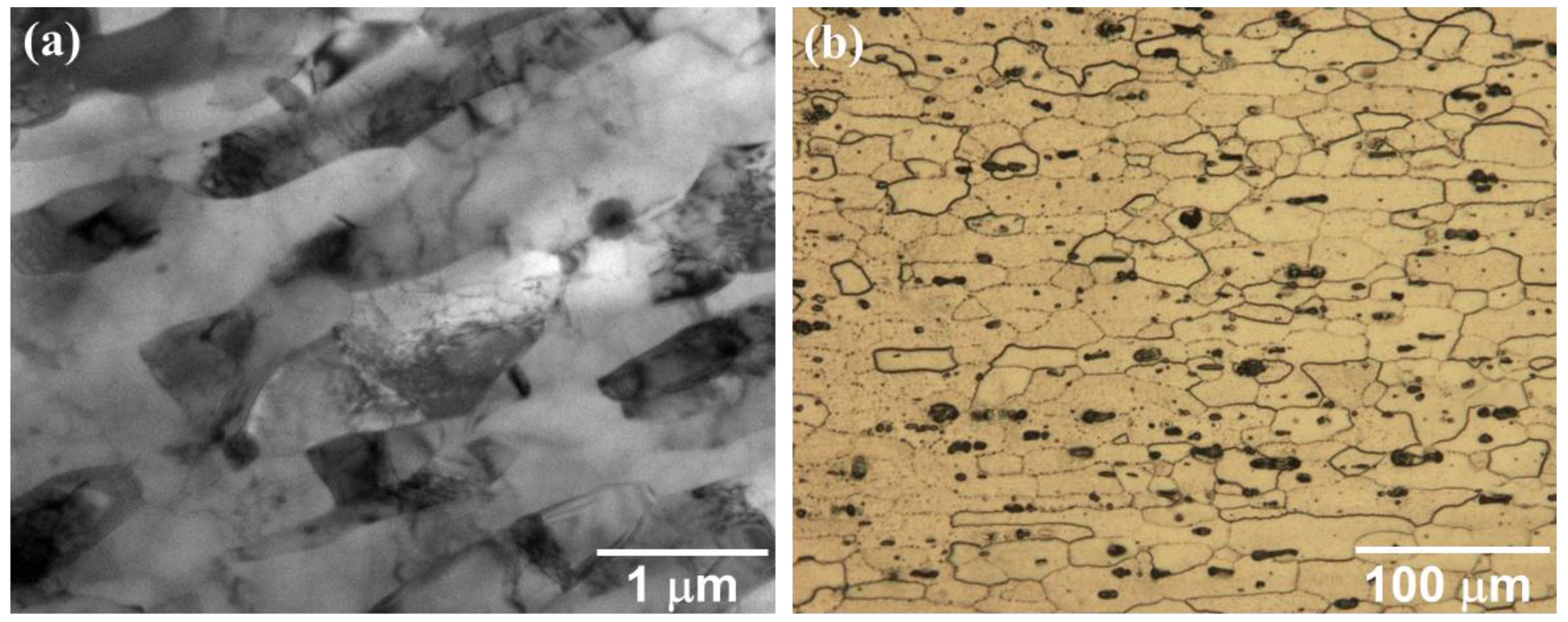
Figure 1 shows the microstructure of the two types of base metals. The UFGed 1050 aluminum alloys have a lamellar structure with an average lamellar width of about 300 nm as shown in
Figure 1a, which is the typical microstructure of the ARB processed materials. These lamellar shaped grains normally have a boundary spacing or grain width much smaller than 1 µm. In addition, the elongated grains in the ARB processed materials are generally surrounded by high angle boundaries, a grain misorientation angle larger than 15°, and high fraction of high angle boundaries of more than 70%. The 6061-T6 aluminum alloys have a coarse equiaxial grain structure with an average grain size of about 18 µm as shown in
Figure 1b. As a typical precipitate hardened aluminum alloy, the mechanical properties of the 6061 Al alloy slightly depend on the grain size of the alloy, but are strongly dominated by the volume fraction, size and distribution of the strengthening precipitates. The 6061 alloy under T6 heat treatment consists of a high density of needle-shape precipitates and a low density of β-Mg
2Si precipitates [
25].
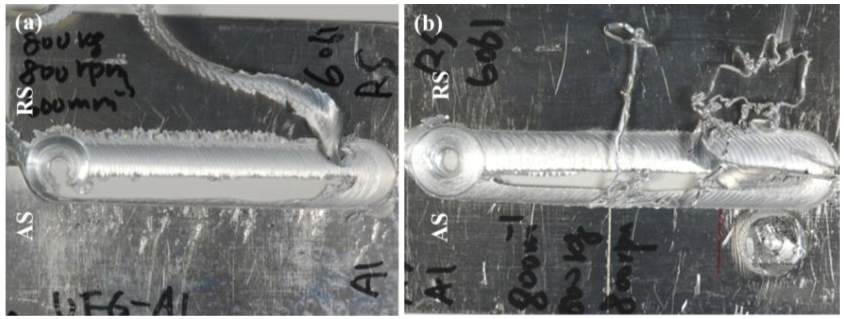
Figure 2 is the photos of the samples produced by FSW at different revolutionary pitches, in which the UFGed 1050 and 6061-T6 aluminum plates were placed on the AS and RS side, respectively. It was found that the dissimilar FSW between these two materials could never been successful. During every welding process, a large defect was formed in the UFGed 1050 aluminum plates and the defect became larger when decreasing the welding speed, as shown in the figures. It was noted that the dissimilar FSW between two aluminum alloys might be difficult since they have quite different deformation characteristics at high temperature. Because the rotating tool on the AS shows the same direction of self-rotation and traveling along the butt interface, the material in the AS generally experiences a higher strain rate and higher temperature than that in the RS [
26,
27]. Therefore, the materials with a low melting point are usually placed on the RS during the dissimilar welding process between two materials with quite different melting points, for example, dissimilar FSW between aluminum and steel alloys [
28,
29]. Sometimes the rotating tool also needs to be offset from the butt interface toward the lower melting temperature materials in order to prevent tool wear or overheating of the lower melting materials. In this study, although the 1050 and 6061 aluminum alloys had very similar melting points, the UFGed 1050 aluminum had a very unstable microstructure, which easily resulted in the dynamic recrystallization and subsequent grain growth at elevated temperature during the welding process. When the UFGed 1050 Al plate was placed on the AS, the materials became very soft and would flow into the RS with the rotation of the tool. However, the 6061 Al on the RS was still hard to be plasticized due to the relatively lower temperature and strain rate. The softened 1050 Al could not be stirred into the 6061 Al on the RS and finally was extruded outside stir zone. As a result, a defect was formed on the AS due to the insufficient amount of the materials. Therefore, placing the UFGed materials on the AS was not suitable for the dissimilar FSW in this study.
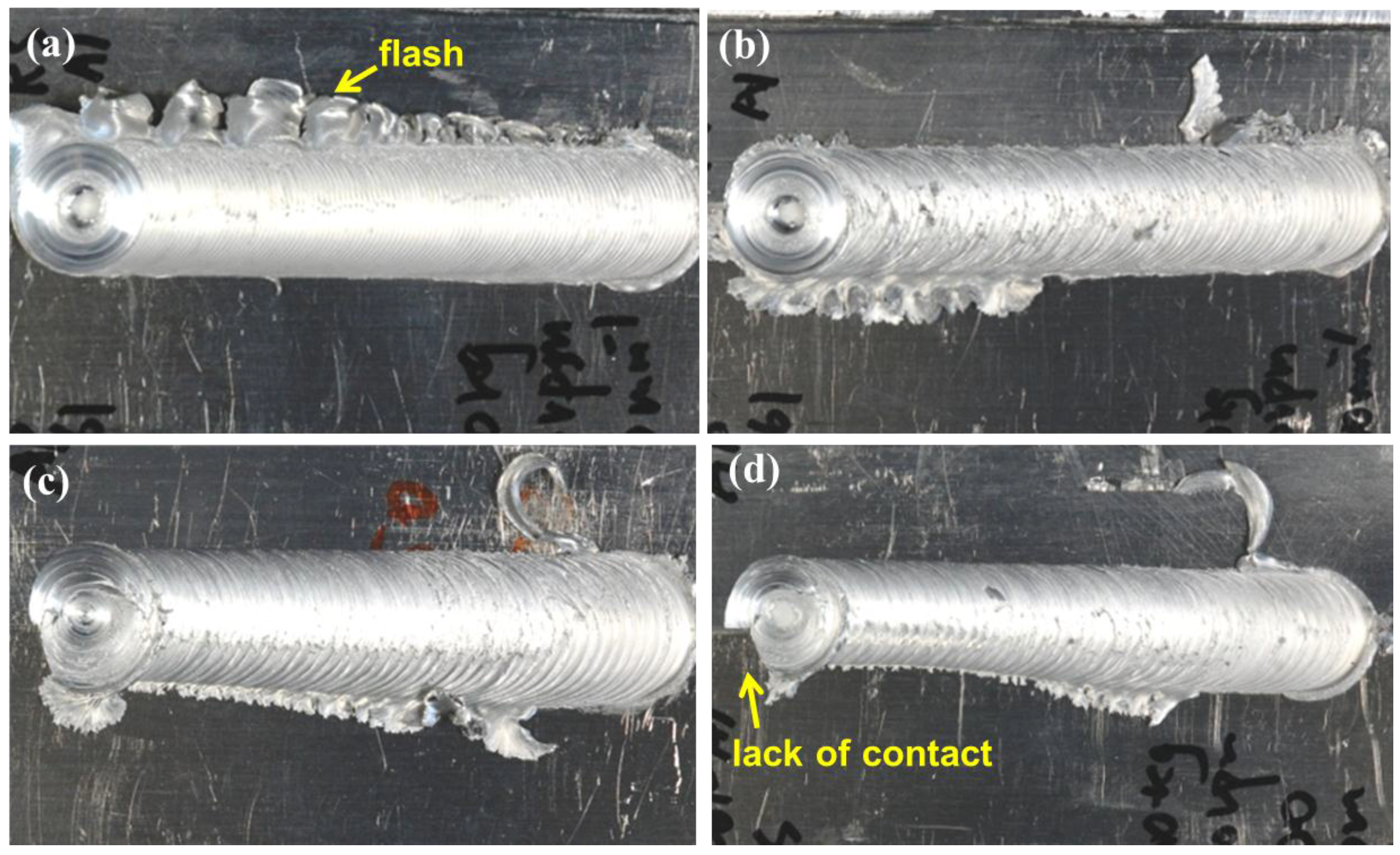
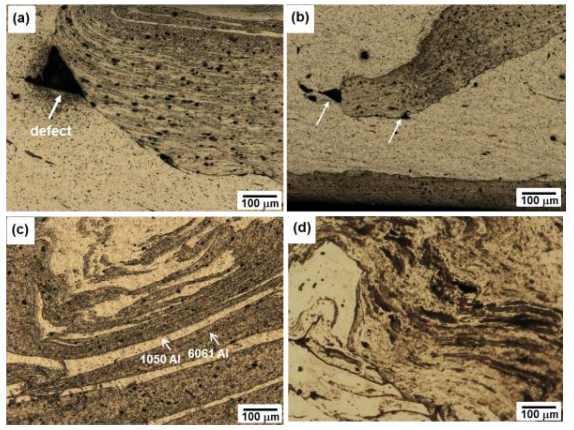
Figure 3 shows photos of the samples produced at different welding speeds, in which the UFGed 1050 Al and 6061-T6 Al alloys were placed on the RS and AS, respectively. The welding was successfully done at the wide revolutionary pitches from 0.5 to 1.25 mm/rev and no obvious defects could be observed based on the appearance of the joints as shown in
Figure 3a,b. However, it was found that at a larger revolutionary pitch of speed of 1 or 1.25 mm/rev, the width of the welding seam became smaller and smaller with the increasing welding distance. It was proposed that the heat input was not sufficient at the higher welding speed during welding process, and the rotating tool could not penetrate deep enough to make the tool shoulder touch the sample surface completely. As a result, a lack of contact between the tool shoulder and the surface of the work-piece was formed, as shown by the arrow in
Figure 3d. Due to the very different material flow of the two materials, the interface could still be observed on the surface of the joint centerline. At the lower revolutionary pitch of less than 0.75 mm/rev, the welding process became very stable and a homogeneous welding seam was obtained, except that a slightly more flash formed on the retreating side of the joint welded at a revolutionary pitch of 0.5 mm/rev. It was revealed that the FSW of dissimilar aluminum alloys should be conducted with suitable locations and in this study the UFGed aluminum plates should be put on the RS.
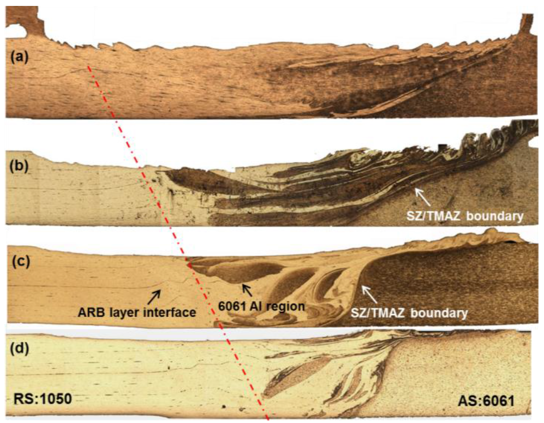
Figure 4 shows the cross-sectional macrostructure of the dissimilar FSW joints between the UFGed 1050 Al and 6061-T6 Al alloy plates, which were obtained at different revolutionary pitches ranging from 0.5 to 1.25 mm/rev. Since the 6061-T6 Al alloy was etched black using Keller’s reagent, the interface and mixing status of the two materials could be readily discerned in the joints. The entire stir zone of the FSW joint consists of the shoulder-affected zone and probe-affected zone. The shoulder affected zone becomes larger at higher rotation speed or lower welding speed, while the probe affected zone shows less sensitive to the welding condition. This has been recently confirmed by the investigation with an adjustable rotating tool [
30]. As a result, a crown-like stir zone is generally formed along the transverse direction, especially for thin plates like in this study. It can be found that the area of the stir zone became larger with the decreasing welding speed for all the samples. At higher revolutionary pitch of 1 and 1.25 mm/rev, the bending of the interface between the alternative layers of the aluminum sheets was observed in the UFGed 1050 Al side near the stir zone as shown by the arrow in
Figure 4c. Generally, a well chemically etched cross-section of the friction stir weld reveals an onion-ring structure in the stir zone with a round flow pattern formed by bright and dark lamellae in the dissimilar aluminum joints [
31,
32]. However, in this study the round flow pattern containing bright and dark lamellae was not observed in the stir zone, probably due to the relatively smaller thickness of the plates. In contrast, roughly two kinds of mixing types could be classified. One was the mixing of dissimilar materials caused by the lower heat input at the high revolutionary pitches of 1 and 1.25 mm/rev. In this case, the size of the stir zone was small and only several prismatic blocks of the 6061 alloy were found in the stir zone. Most of the stir zone was composed of the 1050 Al alloys probably due to its lower viscosity than 6061 alloy at high temperature. In addition, the TMAZ/SZ boundary close to the 6061 Al side was very sharp and nearly vertical, which indicated that the probe-affected zone was very limited due to the fast traveling speed. The other kind of mixing was caused by the higher heat input at the lower revolutionary pitches of 0.75 and 0.5 mm/rev. The shoulder affected zone became much larger and expand downward to the probe affect zone. The material flow of the two materials in the stir zone was stronger and the boundary between the TMAZ/SZ near the 6061-T6 Al side declined more to the base metal. As a result, more material of the 6061-T6 Al alloy was plastically deformed and pushed into the stir zone. Especially, at the low revolutionary pitch of 0.5 m/rev, the two materials could not be easily discerned any more in the stir zone due to the severe mechanical mixing by the rotating tool.
Figure 5 shows the enlarged OM images of the stir zone of the dissimilar FSW joints produced at the different welding speeds. In all the figures except for
Figure 5d, the white and black areas indicated the 1050 Al and the 6061 Al alloys, respectively. As shown in
Figure 4, only several large blocks of the 6061 Al alloys were mixed in the stir zone at the high welding speed.
Figure 5a,b show the boundary between the 6061 Al blocks and the surrounding 1050 Al produced at the revolutionary pitches of 1.25 and 1 mm/rev, respectively. A couple of small welding defects could be distinguished at the corner of the 6061-T6 region. The formation of the defects might be caused by the insufficient plastic deformation at the lower heat input. In addition, it is interesting to note that deformed UFGed 1050 Al layers were observed to be mixed in the region of the 6061-T6 aluminum alloy. In most of the large 6061-T6 blocks, a large number of small segments of white color, which corresponded to the 1050 Al alloy were observed. However, the 6061-T6 aluminum materials were never found to be distributed inside the 1050 Al area. When the revolutionary pitch decreased to 0.75 mm/rev, the mixing of the two materials became much stronger. However, large stripe-like areas of the two different materials were still alternatively distributed together as shown in
Figure 5c. When the revolutionary pitch further decreased to 0.5 mm/rev, the mixing became quite complete and the two different materials could not be easily discerned under by OM observation, as shown in
Figure 5d.
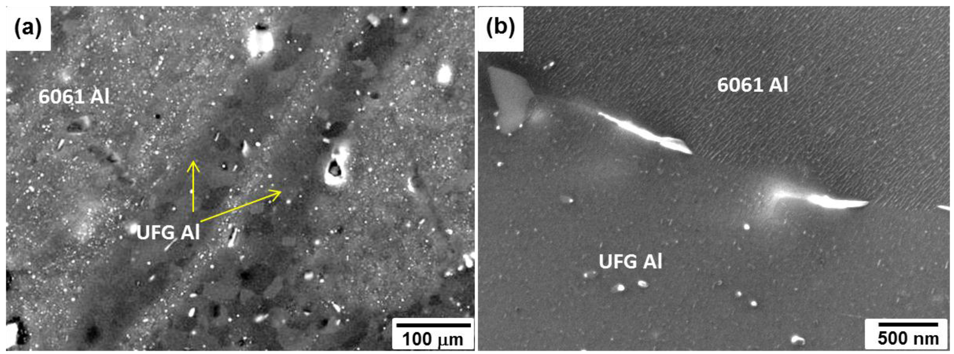
To reveal how the two materials were mixed in the stir zone, SEM observations of the cross-sectional microstructure of the joints were carried out. As a typical example,
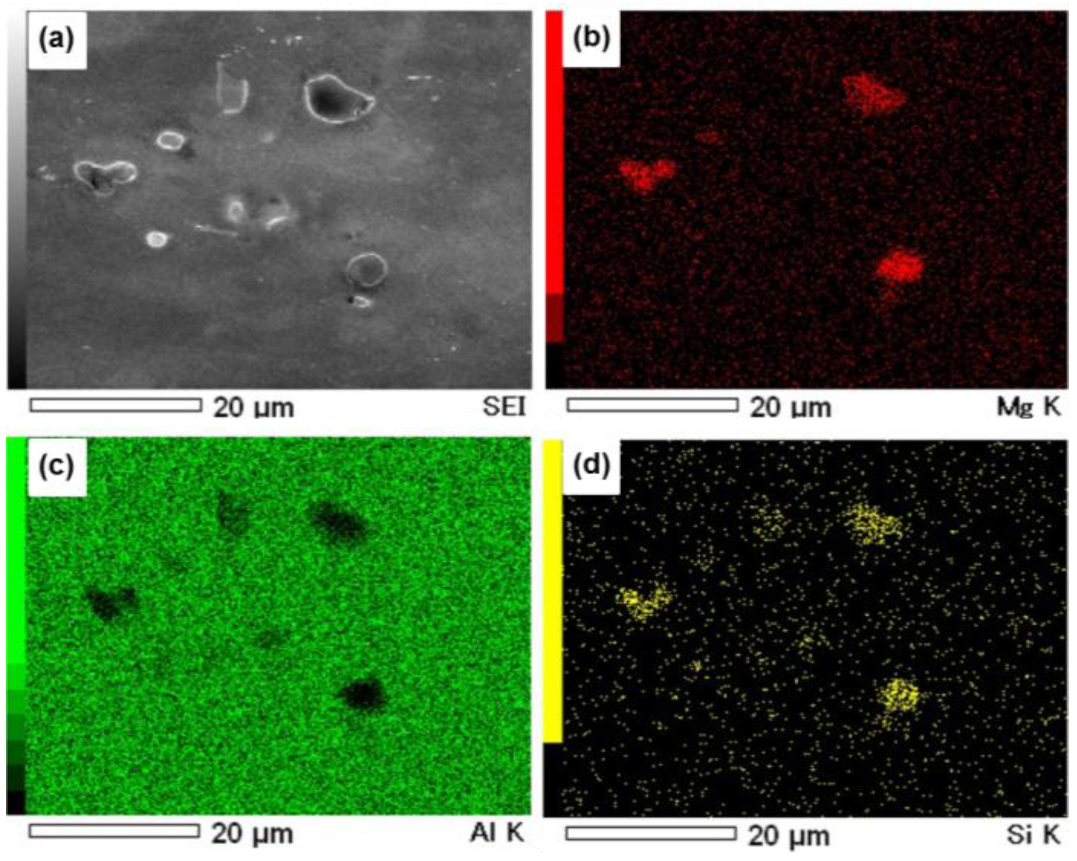
Figure 6 shows the microstructure of the joints produced at a revolutionary pitch of 0.75 mm/rev. In most parts of the area it showed a very high density of white particles, while in the other parts particles were hardly observed. From the element mapping by Energy Dispersive X-ray Spectroscopy EDS measurement as shown in
Figure 7, the particles were confirmed to be the Mg
2Si phase. The coarsening of the Mg
2Si particles in the 6061 Al alloy area due to the quite high heat input generated during the FSW process, was also observed in the FSW of similar 6xxx aluminum alloys [
33]. The distribution of particles in the 6061-T6 Al alloy made it easy to be distinguished from the area of the 1050 Al, which contained no particles. The 1050 Al part was like a long stripe with a width of about 10 µm in the mixture of the two materials, which was very likely caused by the flow stress during welding.
Figure 6b shows the boundary between the 6061 and 1050 Al alloys. The Mg
2Si particles were found distributed on the boundary, which played a role in pinning of the migration of the grain boundary during the welding process. In addition, sub-grains with the average size of several nanometers were formed inside the 6061 Al grains, which were also found in the dissimilar friction stir spot welding between UFGed 1050 and 6061-T6 Al alloys [
24].
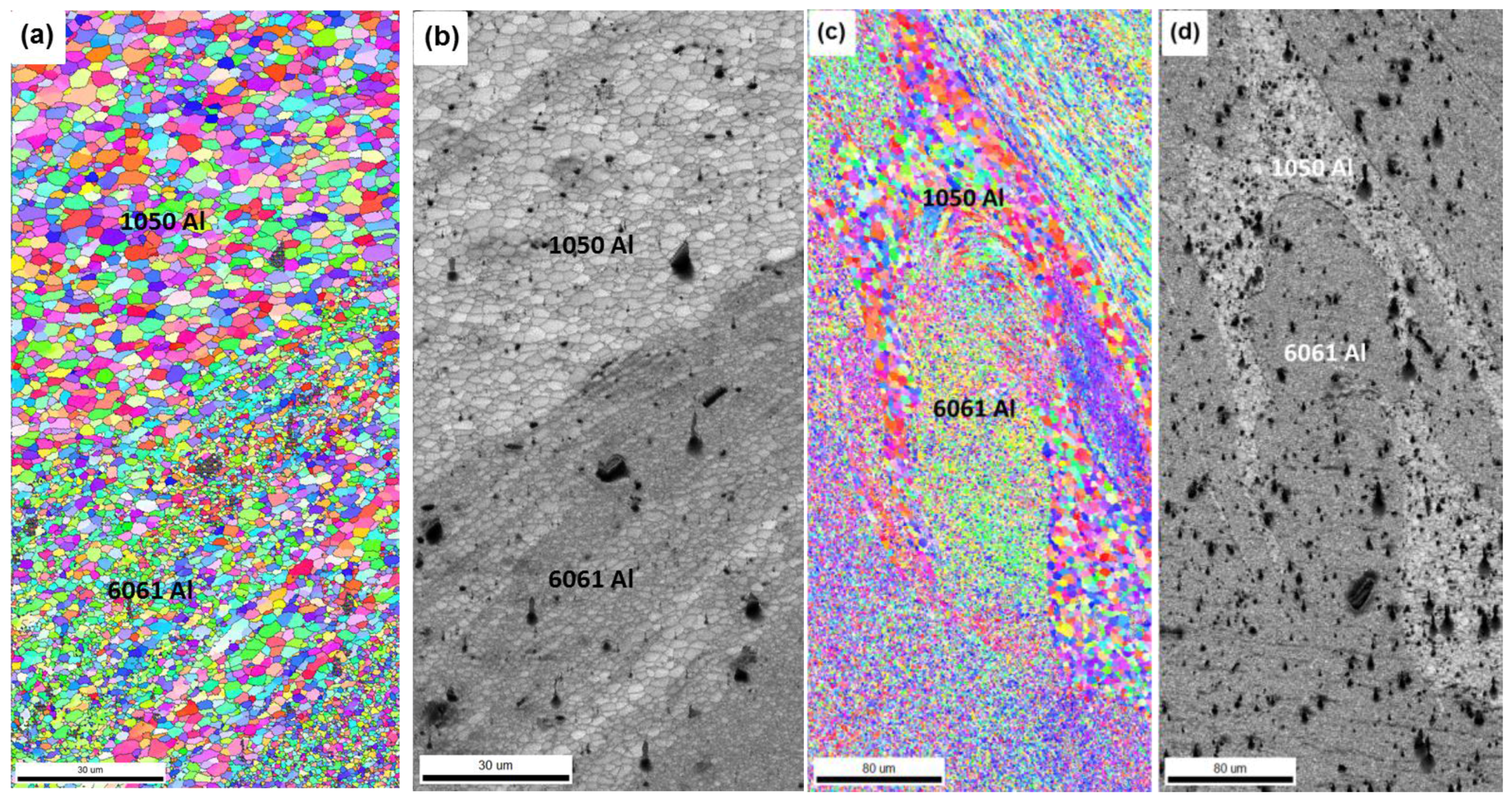
Figure 8 shows the EBSD maps measured in the mixed area of the stir zone, in which only the high angle boundary larger than 15° was plotted. The black area in the maps indicated the distribution of the coarsened Mg
2Si precipitates due to the generated Kikuchi pattern with a low confidence index (CI) value.
Figure 8a shows the EBSD-IPF map of the mixed area in the stir zone of the joint produced at a revolutionary pitch of 0.75 mm/rev. An obvious bimodal structure containing two types of grains with quite different grain size could be observed. One type of grain structure had a larger average grain size of about 2.6 µm, while the other type of grain structure had a smaller average grain size of about 1.1 µm.
Figure 8b shows the corresponding image quality (IQ) map, in which the matrix of the 6061 Al alloy contains additional elements like Mg and Cu and therefore its crystalline lattice deviated from that of the pure Al. Another reason for the low IQ value of the 6061 Al region might be caused by the formation of a high density of subgrain, in which the density of dislocation might be higher. Therefore, the area with the larger grain size corresponded to the 1050 Al alloys, while the area with the smaller grain size corresponded to the 6061 Al alloys.
Figure 8c,d shows the IPF and IQ map of the joint produced at a revolutionary pitch of 0.5 mm/rev, when a higher heat was generated during welding. The mixing of the two materials became stronger; however, it still can be distinguished due to their quite different grain size and IQ value. In this case, the average grain size of the 1050 Al and 6061 Al were 4.5 and 1.5 µm, respectively. With the increase in the heat input during welding, the grain growth of the 1050 Al increases faster than that of the 6061 Al alloys.
It is interesting to note that in the stir zone the 1050 Al showed an average grain size quite larger than 300 nm of the BM, while the 6061 Al showed a fairly refined microstructure compared with that 18 µm of the BM. In addition, both 1050 Al and 6061Al had equiaxial grain structure and large fraction of high angle grain boundary, indicating the occurrence of dynamic recrystallization. Because FSW is a kind of high strain rate plastic deformation at high temperature, the evolution of the grain structure in the stir zone during the FSW strongly depends on the initial microstructure such as the grain boundary structure, grain size, dislocation density, etc., of the base metal [
34]. Usually, when the FSW process is applied to the conventional metals or alloys, a very refined microstructure will be formed in the stir zone of the joints. The grain refinement process is generally believed to be driven by the grain subdivision or the continuous dynamic recrystallization, termed geometric dynamic recrystallization which was first recognized by Humphreys and McQeen [
35,
36,
37]. The continuous dynamic recrystallization is characterized by a strain-induced progressive rotation of the subgrains with little boundary migration during the FSW process and is prone to occur at grain boundary in aluminum alloys with a high level of solute like Mg and Zn, by progressive lattice rotation.
The pure Al alloy has a high stacking fault energy and the UFGed 1050 Al produced by the SPD process generally showed a fairly unstable microstructure upon heat treatment. That is because unlike conventional metals or alloys, the as-ARB processed materials contain a large quantity of vacancies and dislocations generated by the severe plastic deformation. Therefore, the UFGed alloys are very likely to be structurally recovered at a relatively low temperature to decrease the defect density within the grains. At the same time, continuous grain growth took place and the mean grain size increased. Similarly, during the dissimilar FSW process in this study, the area of the 1050 Al showed a fairly coarse grain structure, which resulted in an obvious hardness reduction in the stir zone.
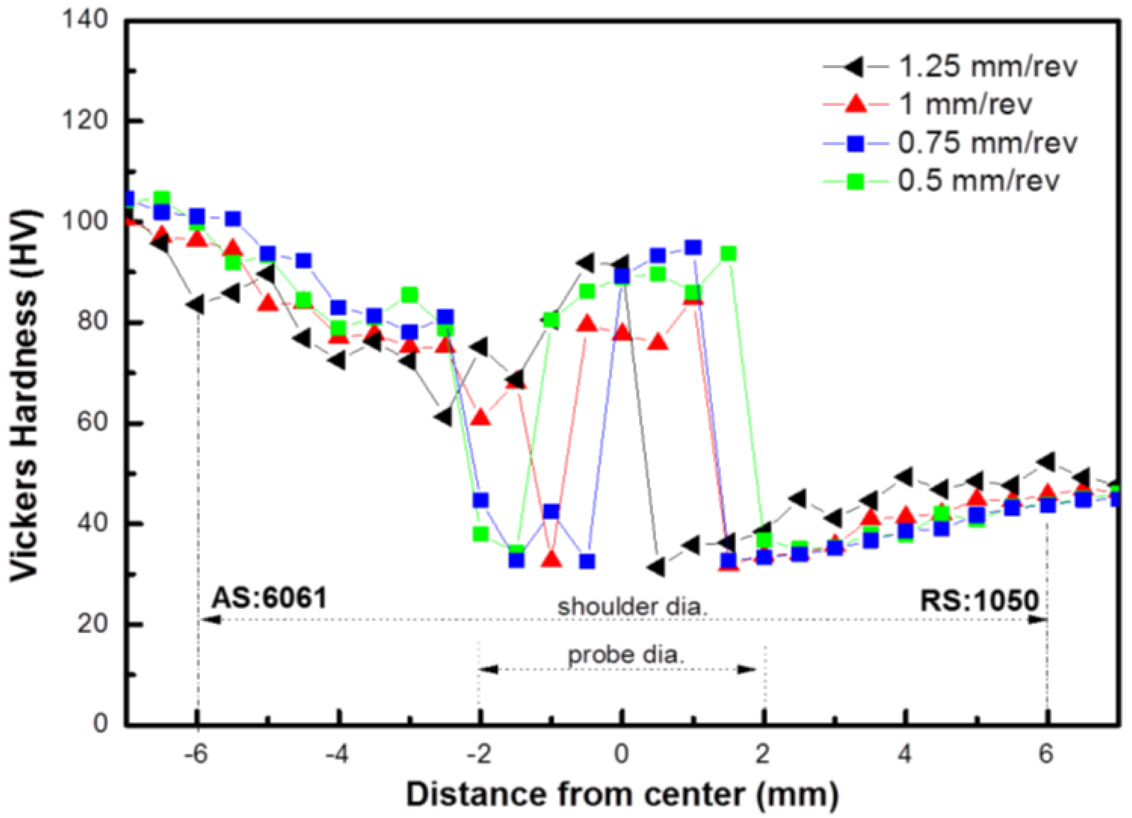
Figure 9 shows the microhardness profile for the dissimilar FSW joints produced at different welding speeds. The variation in the hardness value corresponded to the typical microstructural zones. For all the specimens, the base metal of both the UFGed 1050 and 6061-T6 Al alloys showed the highest value. From the BM to HAZ, a gradual decrease in microhardness was observed for both materials. For the 6061-T6 alloy, the decrease was due to the accelerated solid solution of precipitates and the simultaneous occurrence of coarsening of particles caused by the weld thermal cycles. However, the stir zone also showed some regions with a high hardness value similar to that of the base metal, which was caused by the significantly refined grain size, while in the UFG 1050 Al side, the decrease in the hardness was mainly caused by the grain growth and the dislocation density.
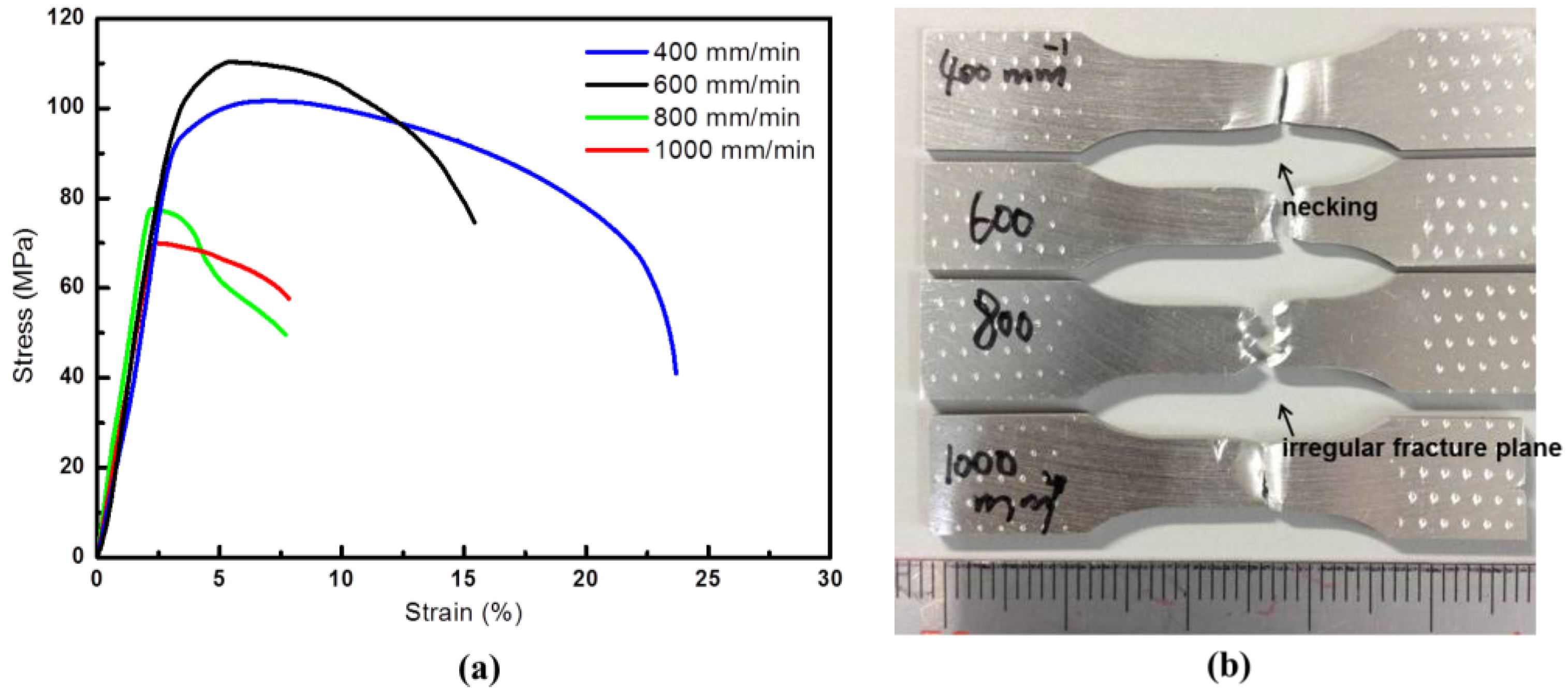
Figure 10 shows the tensile strain-stress curves of the specimens produced at different welding speed. For the specimens produced at the revolutionary pitches of 1.25 and 1 mm/rev, both the tensile strength and elongation were lower than the other specimens produced at the smaller revolutionary pitches. It is proposed that the mixing of the two materials was not sufficient and several large blocks of different materials were formed in the stir zone. In addition, a couple of defects with several micrometers in size were found at the corner of the 6061-T6 aluminum block that may more or less decrease the strength of the joints. When the revolutionary pitch decreased to 0.75 or 0.5 mm/rev, the high heat input enhanced the plastic deformation and therefore led to further mixing of the two materials in the stir zone. The microstructure of the stir zone also became more homogeneous. As a result, the tensile strength and elongation increased to about 110 MPa and 13% for the sample welded at 0.75 mm/rev and 110 MPa and 22.5% for the sample welded at 0.5 mm/rev. The largest joint efficient was therefore about 55% with respect to the UFG 1050 Al base metal. However, the joints strength was still much larger than the ultimate strength of the commercial coarse grain structured 1050 Al alloy. However, too much heat input in the joints produced at 0.5 mm/rev resulted in serious grain growth of both materials, especially the 1050 Al alloy parts. The tensile strength slightly decreased again, however, with compensation of a much increased elongation.
From the photos showing the appearance of the fractured tensile specimen, the joints produced at high welding speeds showed a brittle fracture, and even some irregular zigzag edges near the fracture plane could be found. In contrast, the joints produced at a revolutionary pitch of 0.5 mm/rev showed obvious necking near the fractured plane, indicative of ductile failure of the specimen.
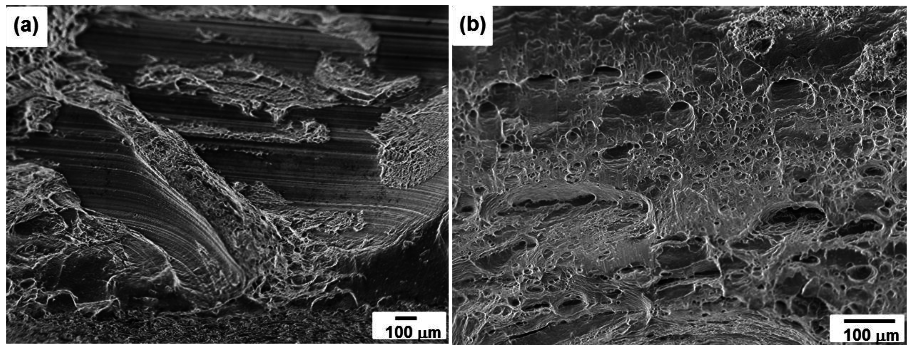
Figure 11 shows the morphologies of the fracture plane after tensile testing of the dissimilar FSW joints produced at 1 and 0.5 mm/rev, corresponding to the brittle and ductile kinds of fracture mode. For the specimen produced at 1 mm/rev, several irregular fractured planes were observed as shown in
Figure 11a. Some dimple patterns could be found in some of the fracture planes, while some other planes showed tearing of the specimens. For the specimen produced at a welding speed of 0.5 mm/rev, the fracture plane had typical dimple patterns as shown in
Figure 11b, indicating ductile failure of the specimen.


