
18Ni300 Maraging Steel Lattice Structures Fabricated via Laser Powder Bed Fusion—Mechanical Behavior and Gas Permeability
 ,
,  , and
, and
Abstract
:1. Introduction
2. Experimental Procedure
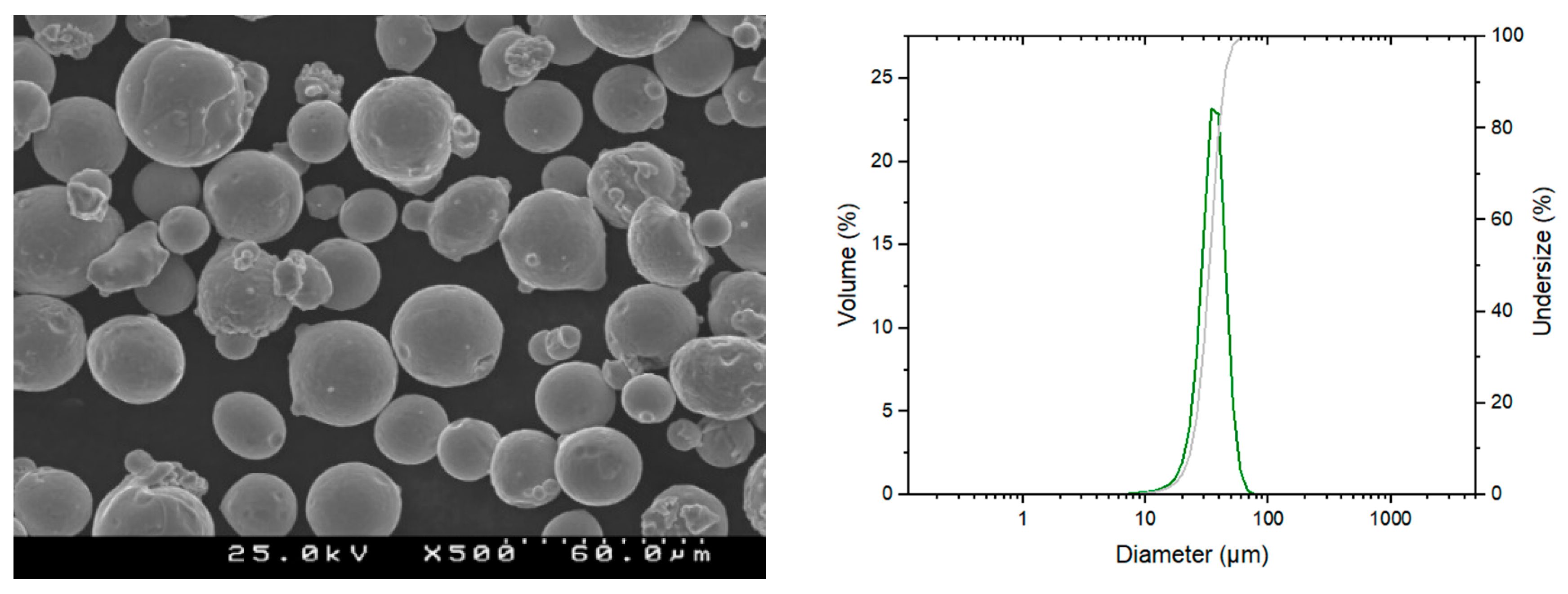
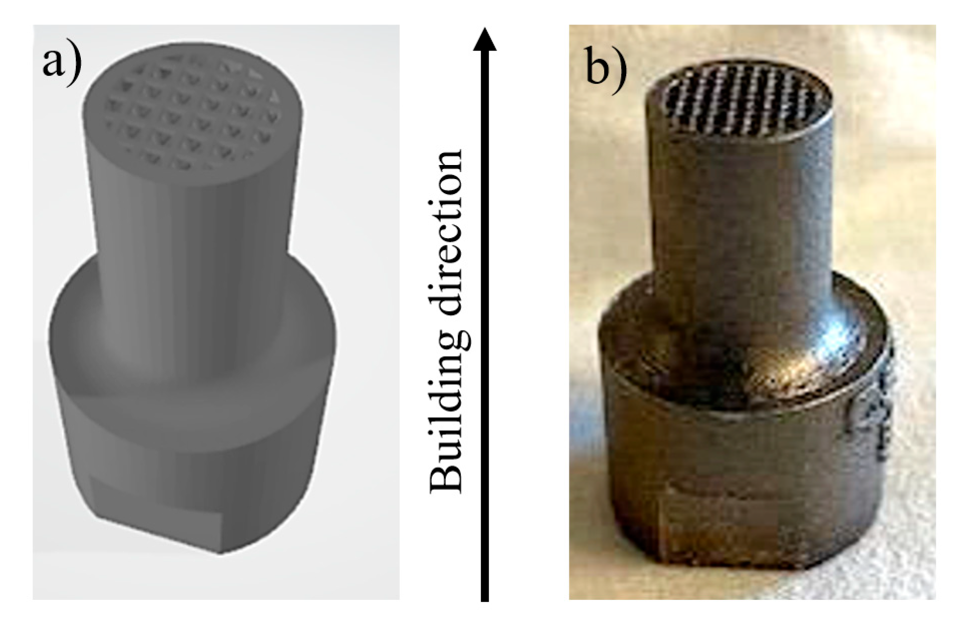
2.1. Materials and SLM Fabrication Details

| Element | Ni | Co | Mo | Ti | C | Others |
|---|---|---|---|---|---|---|
| wt. (%) | 17 to 19 | 7 to 10 | 4.5 to 5.2 | 0.3 to 1.2 | ≤0.03 | Bal. |
2.2. Post-Fabrication Heat Treatment
2.3. Characterization and Testing
2.3.1. Lattice Structures’ Characterization
2.3.2. Phase Identification and Microstructure
2.3.3. Compression Tests
2.3.4. Permeability Tests
3. Results and Discussion
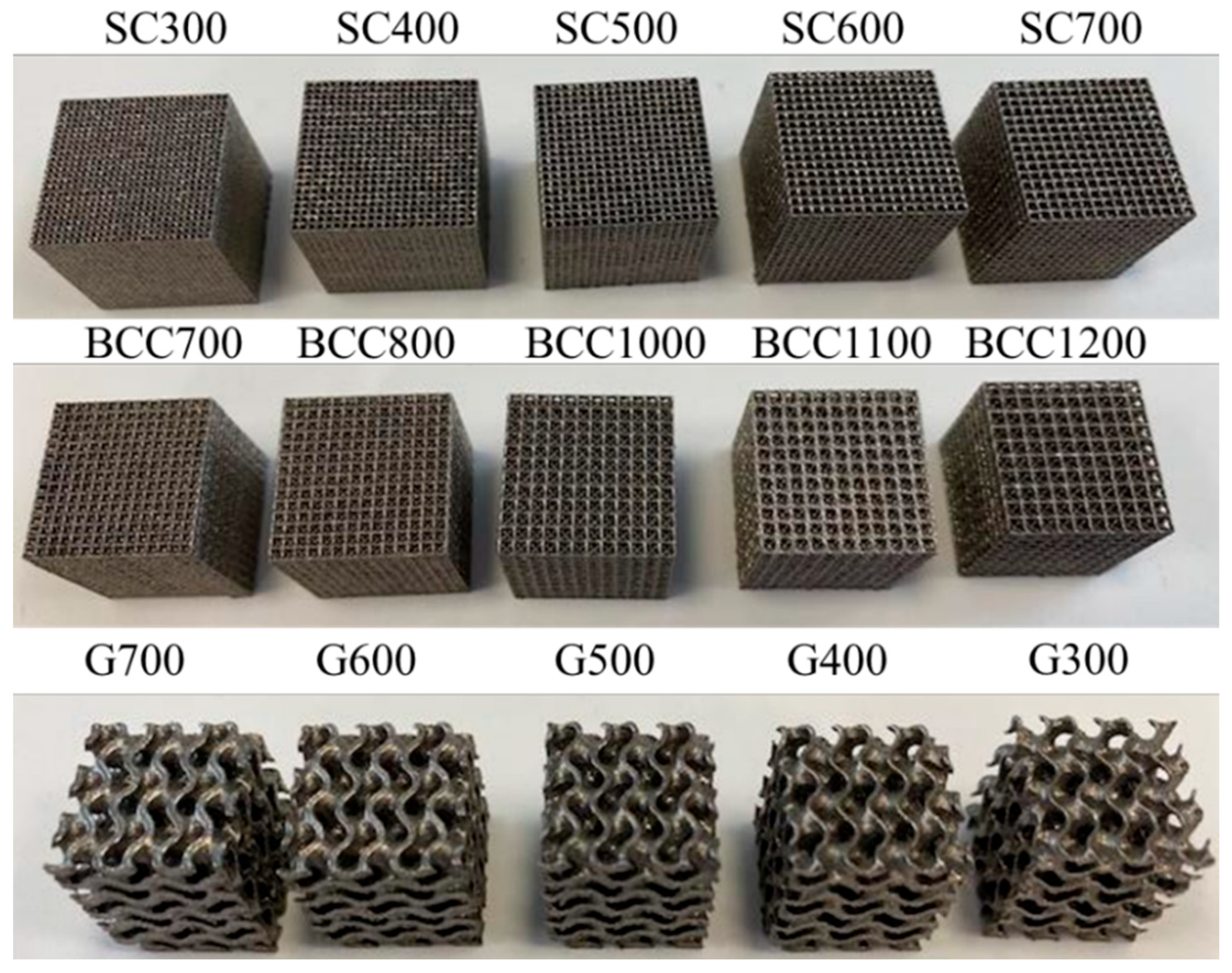
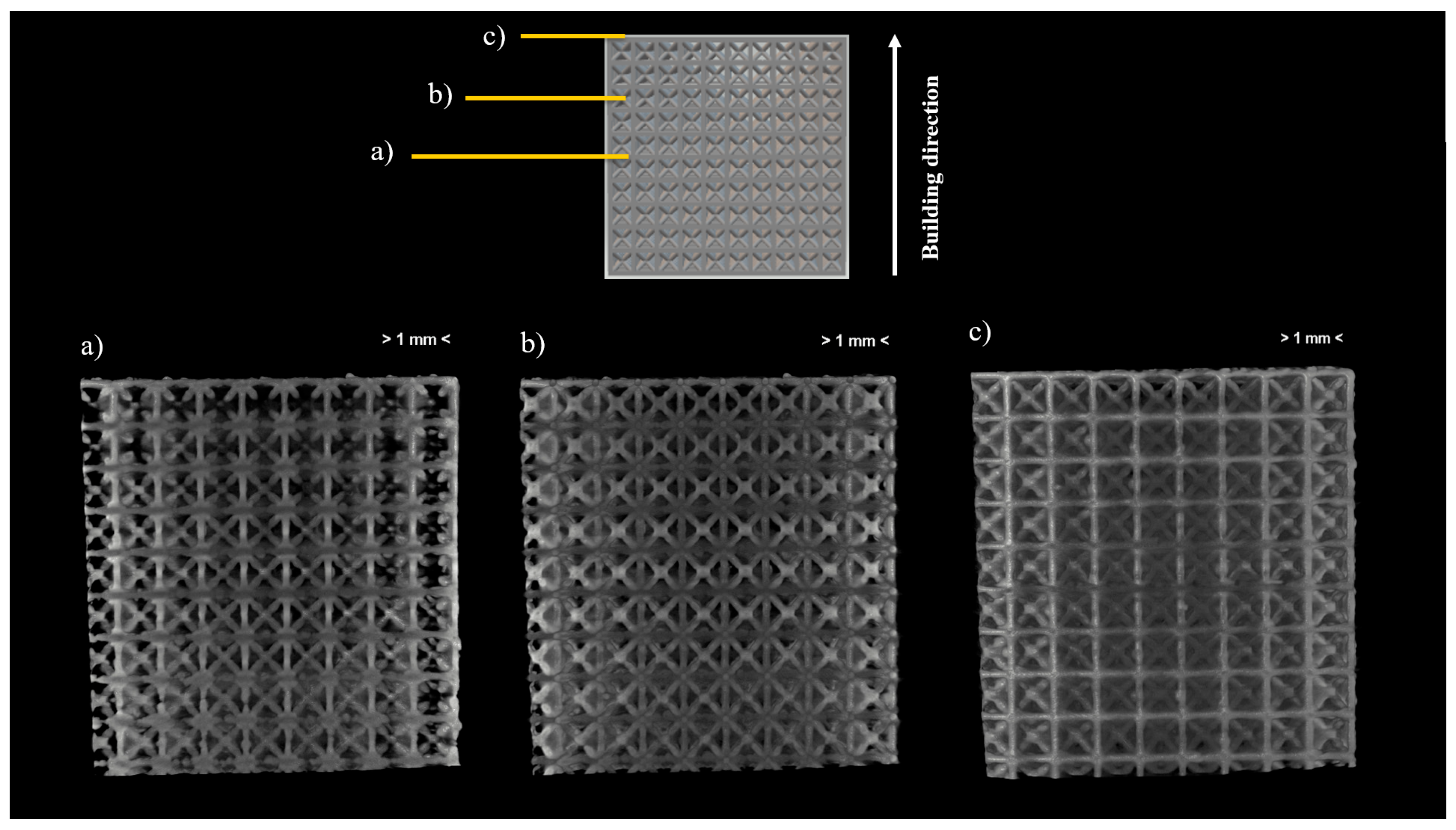
3.1. Morphological and Dimensional Characterization
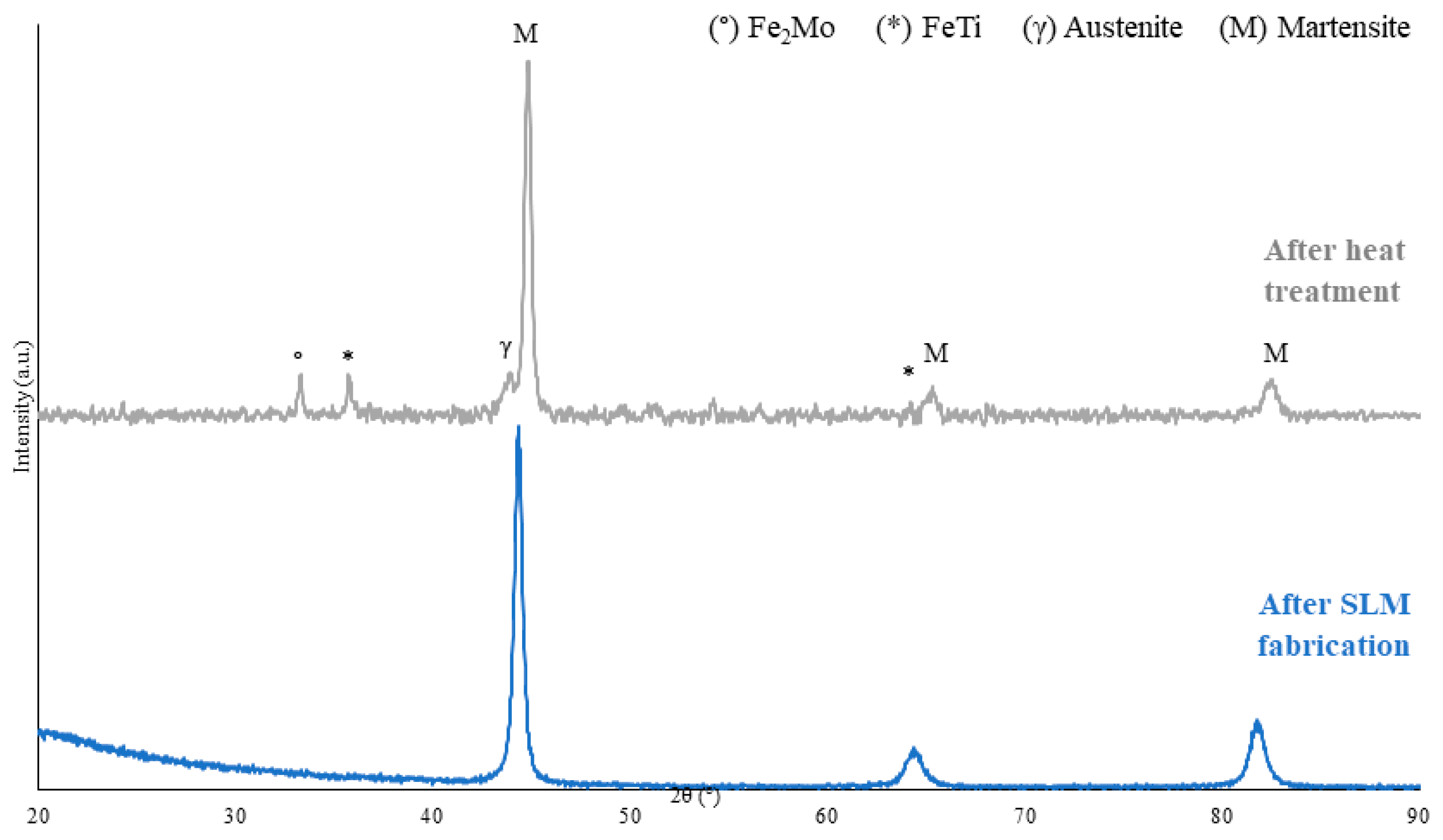
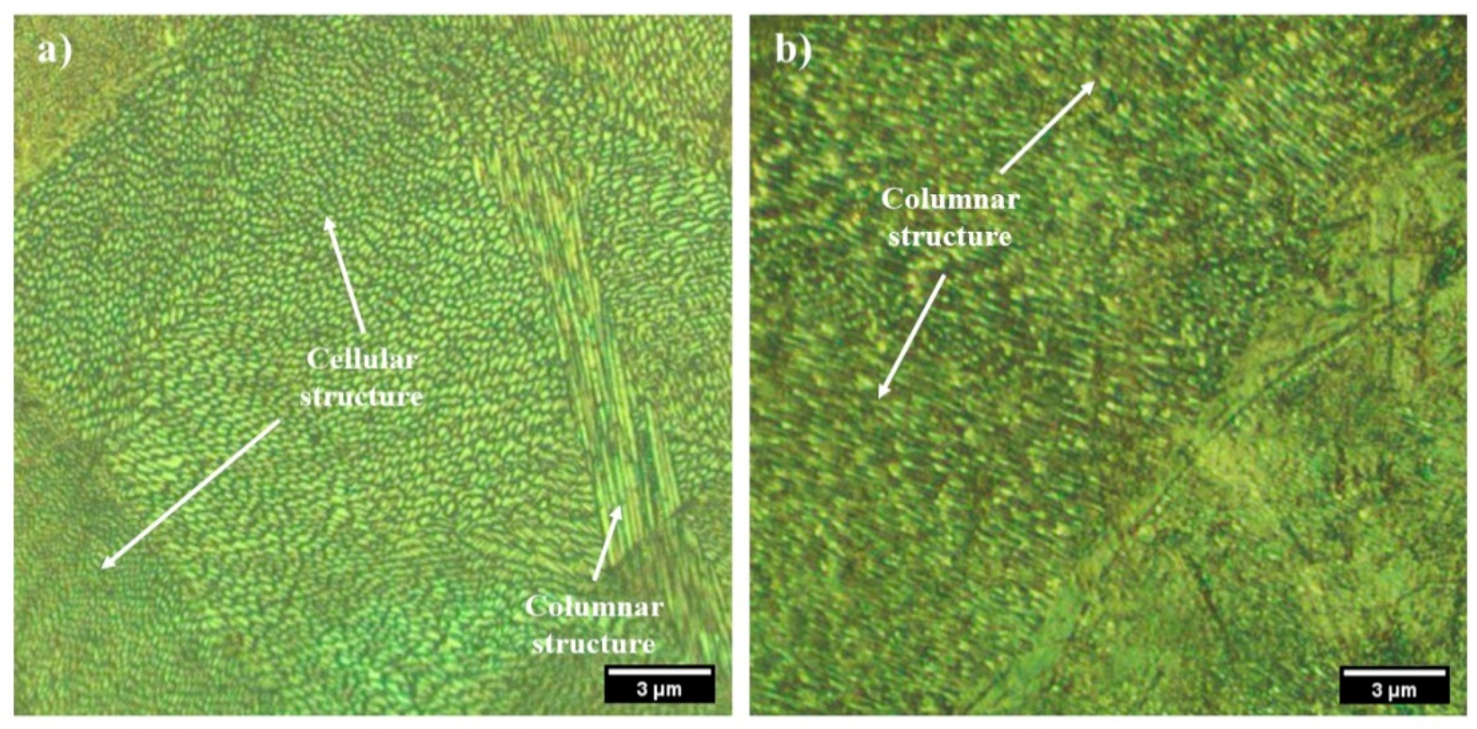
3.2. Phase Identification and Microstructure
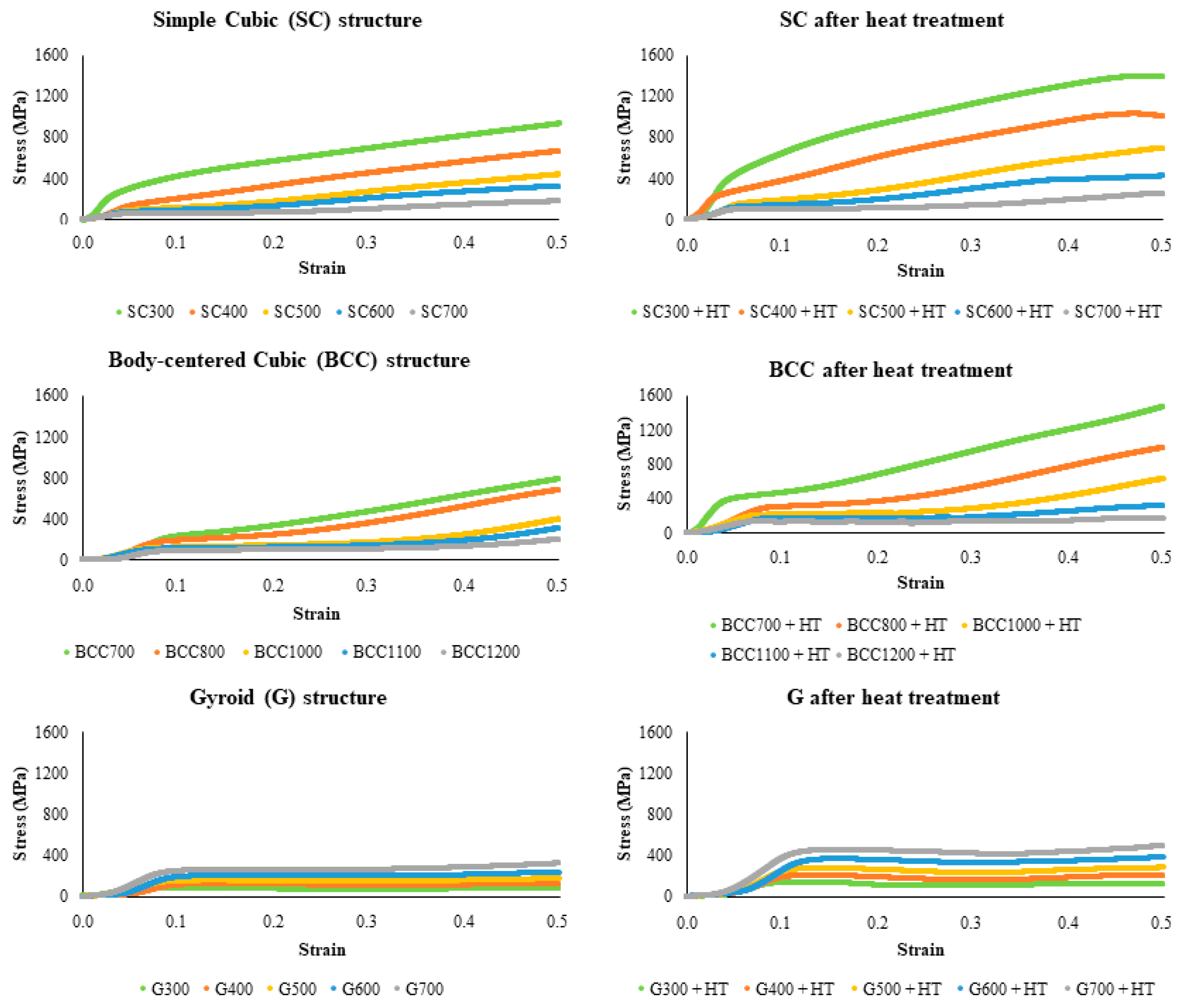
3.3. Mechanical Testing
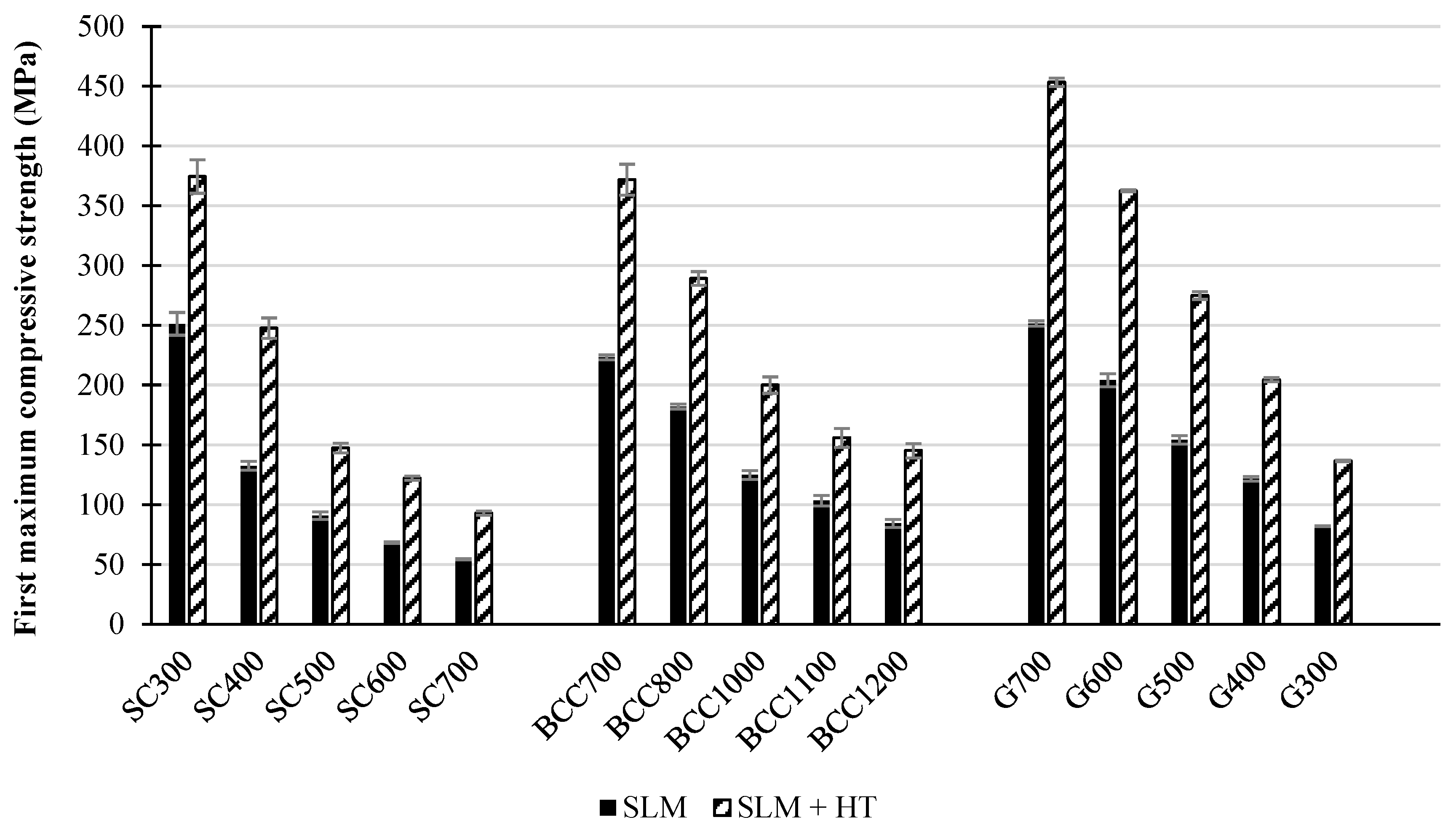
3.3.1. First Maximum Compressive Strength
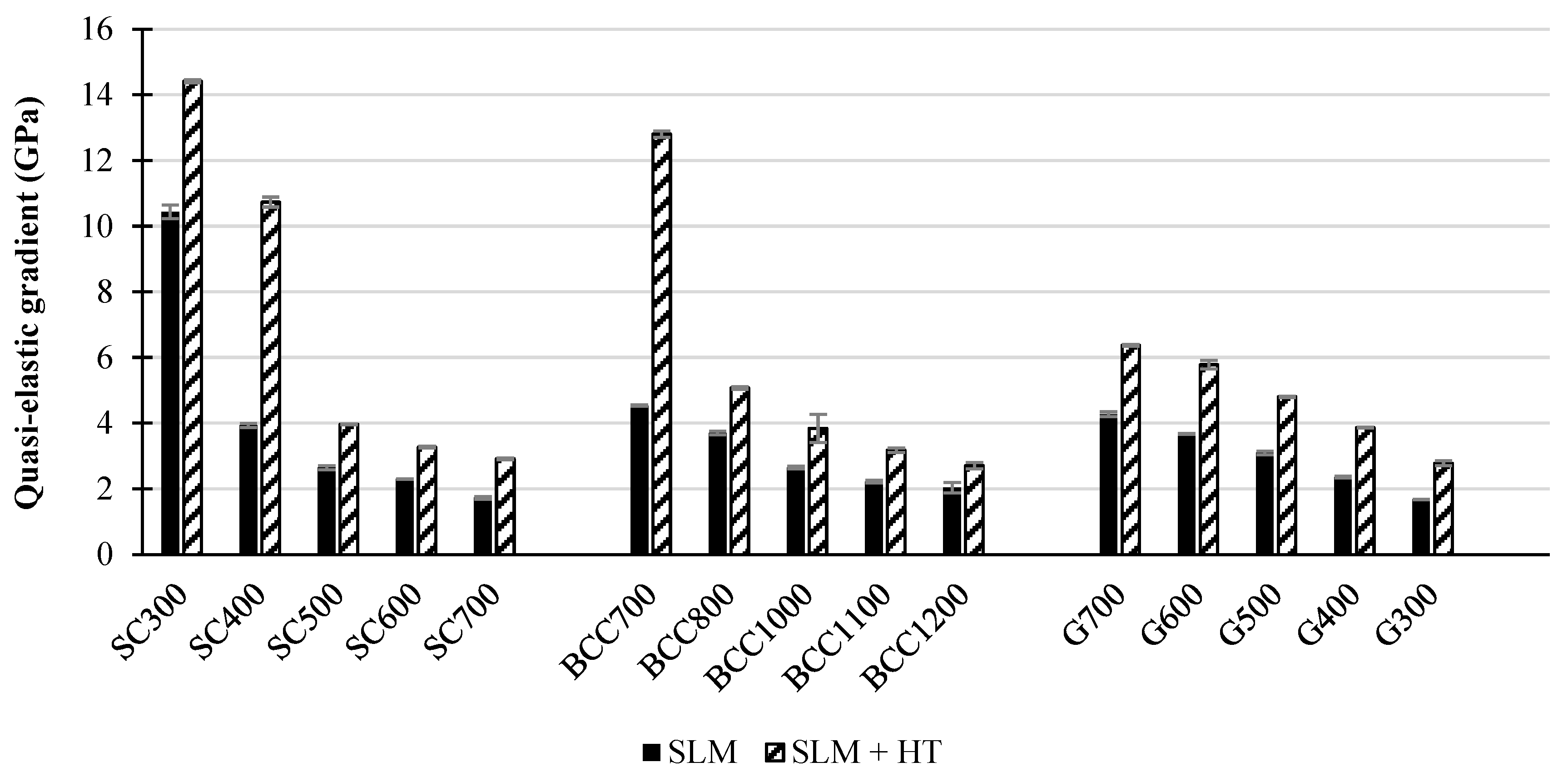
3.3.2. Quasi-Elastic Gradient
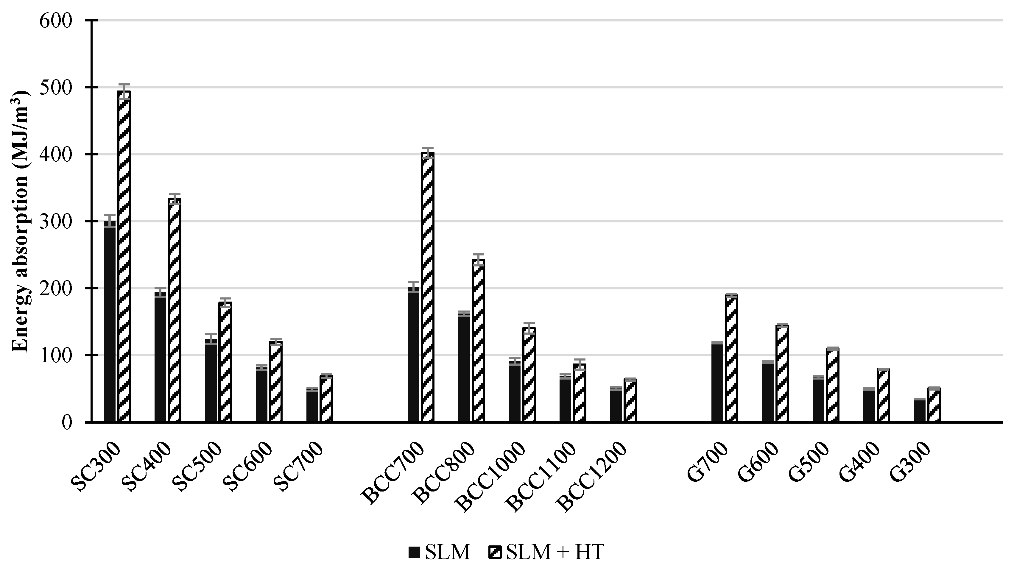
3.3.3. Energy Absorption (W)
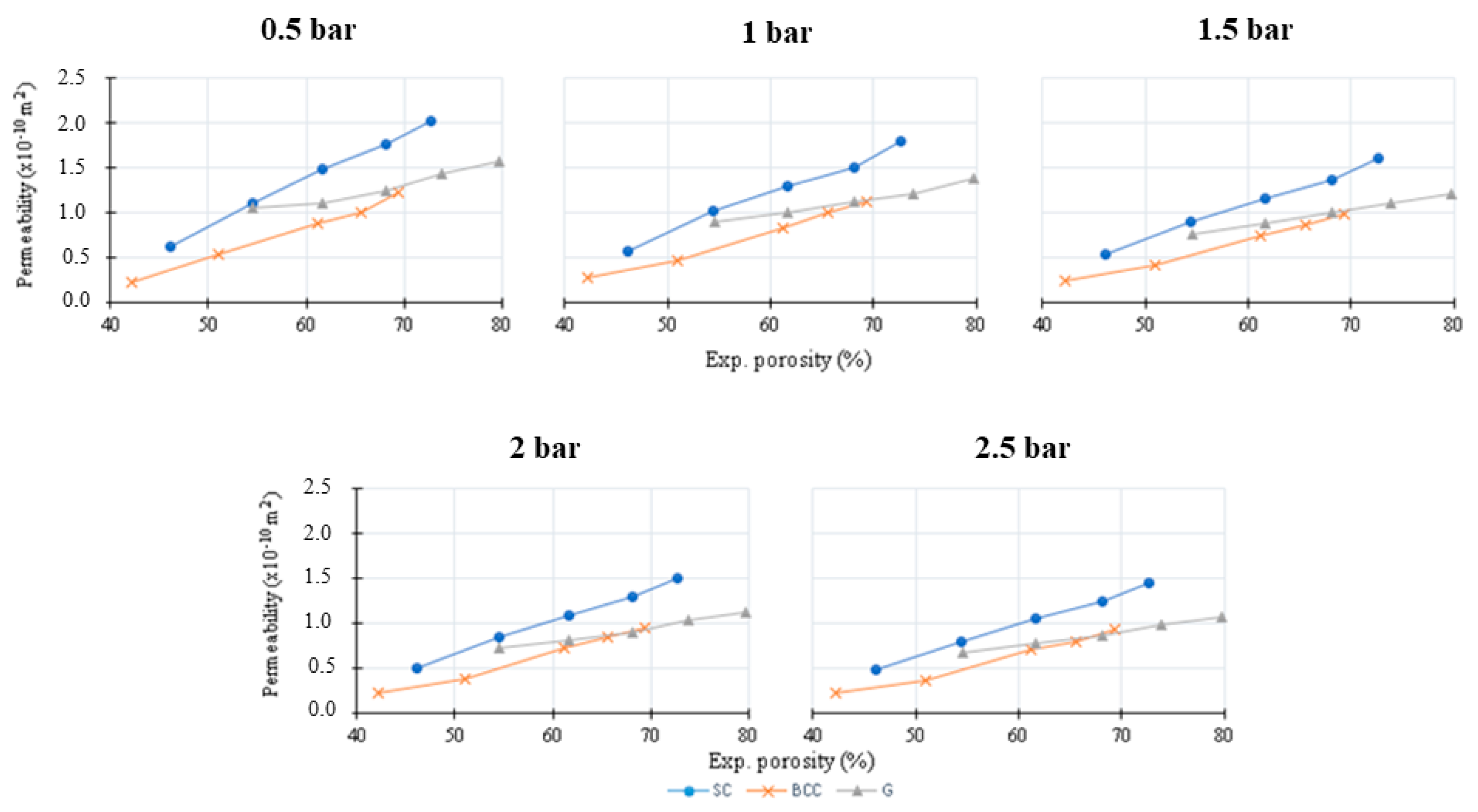
3.4. Permeability Testing
4. Conclusions
Author Contributions
Funding
Data Availability Statement
Acknowledgments
Conflicts of Interest
References
- Maconachie, T.; Leary, M.; Lozanovski, B.; Zhang, X.; Qian, M.; Faruque, O.; Brandt, M. SLM lattice structures: Properties, performance, applications and challenges. Mater. Des. 2019, 183, 108137. [Google Scholar] [CrossRef]
- Babamiri, B.B.; Askari, H.; Hazeli, K. Deformation mechanisms and post-yielding behavior of additively manufactured lattice structures. Mater. Des. 2020, 188, 108443. [Google Scholar] [CrossRef]
- Helou, M.; Kara, S. Design, analysis and manufacturing of lattice structures: An overview. Int. J. Comput. Integr. Manuf. 2018, 31, 243–261. [Google Scholar] [CrossRef]
- Riva, L.; Ginestra, P.S.; Ceretti, E. Mechanical characterization and properties of laser-based powder bed-fused lattice structures: A review. Int. J. Adv. Manuf. Technol. 2021, 113, 649–671. [Google Scholar] [CrossRef]
- Zadpoor, A.A. Mechanical performance of additively manufactured meta-biomaterials. Acta Biomater. 2019, 85, 41–59. [Google Scholar] [CrossRef] [PubMed]
- Mahshid, R.; Hansen, H.N.; Højbjerre, K.L. Strength analysis and modeling of cellular lattice structures manufactured using selective laser melting for tooling applications. Mater. Des. 2016, 104, 276–283. [Google Scholar] [CrossRef]
- Chouhan, G.; Gunji, B. Additive manufacturing TPMS lattice structures: Experimental study on airflow resistivity. Results Mater. 2023, 20, 100478. [Google Scholar] [CrossRef]
- ISO 17296-2:2015; Additive Manufacturing—General Principles—Part 2: Overview of Process Categories and Feedstock. ISO: Geneva, Switzerland, 2015. Available online: https://www.iso.org/standard/61626.html (accessed on 5 February 2022).
- Nouri, A.; Rohani Shirvan, A.; Li, Y.; Wen, C. Additive manufacturing of metallic and polymeric load-bearing biomaterials using laser powder bed fusion: A review. J. Mater. Sci. Technol. 2021, 94, 196–215. [Google Scholar] [CrossRef]
- Sola, A.; Nouri, A. Microstructural porosity in additive manufacturing: The formation and detection of pores in metal parts fabricated by powder bed fusion. J. Adv. Manuf. Process. 2019, 1, e10021. [Google Scholar] [CrossRef]
- Monroy, K.; Delgado, J.; Ciurana, J. Study of the pore formation on CoCrMo alloys by selective laser melting manufacturing process. Procedia Eng. 2013, 63, 361–369. [Google Scholar] [CrossRef]
- Qi, D.; Yu, H.; Liu, M.; Huang, H.; Xu, S.; Xia, Y.; Qian, G.; Wu, W. Mechanical behaviors of SLM additive manufactured octet-truss and truncated-octahedron lattice structures with uniform and taper beams. Int. J. Mech. Sci. 2019, 163, 105091. [Google Scholar] [CrossRef]
- Dallago, M.; Zanini, F.; Carmignato, S.; Pasini, D.; Benedetti, M. Effect of the geometrical defectiveness on the mechanical properties of SLM biomedical Ti6Al4V lattices. Procedia Struct. Integr. 2018, 13, 161–167. [Google Scholar] [CrossRef]
- Yan, C.; Hao, L.; Hussein, A.; Raymont, D. Evaluations of cellular lattice structures manufactured using selective laser melting. Int. J. Mach. Tools Manuf. 2012, 62, 32–38. [Google Scholar] [CrossRef]
- Giganto, S.; Martínez-Pellitero, S.; Barreiro, J.; Zapico, P. Influence of 17-4 PH stainless steel powder recycling on properties of SLM additive manufactured parts. J. Mater. Res. Technol. 2022, 16, 1647–1658. [Google Scholar] [CrossRef]
- Wang, Y.; Guo, W.; Xie, Y.; Li, H.; Zeng, C.; Xu, M.; Zhang, H. In-situ monitoring plume, spattering behavior and revealing their relationship with melt flow in laser powder bed fusion of nickel-based superalloy. J. Mater. Sci. Technol. 2024, 177, 44–58. [Google Scholar] [CrossRef]
- Takata, N.; Nishida, R.; Suzuki, A.; Kobashi, M.; Kato, M. Crystallographic features of microstructure in maraging steel fabricated by selective laser melting. Metals 2018, 8, 440. [Google Scholar] [CrossRef]
- Laleh, M.; Sadeghi, E.; Revilla, R.I.; Chao, Q.; Haghdadi, N.; Hughes, A.E.; Xu, W.; De Graeve, I.; Qian, M.; Gibson, I.; et al. Heat treatment for metal additive manufacturing. Prog. Mater. Sci. 2023, 133, 101051. [Google Scholar] [CrossRef]
- Dehgahi, S.; Sanjari, M.; Ghoncheh, M.H.; Shalchi Amirkhiz, B.; Mohammadi, M. Concurrent improvement of strength and ductility in heat-treated C300 maraging steels produced by laser powder bed fusion technique. Addit. Manuf. 2021, 39, 101847. [Google Scholar] [CrossRef]
- Mutua, J.; Nakata, S.; Onda, T.; Chen, Z.C. Optimization of selective laser melting parameters and influence of post heat treatment on microstructure and mechanical properties of maraging steel. Mater. Des. 2018, 139, 486–497. [Google Scholar] [CrossRef]
- Ferreira, D.F.S.; Miranda, G.; Oliveira, F.J.; Oliveira, J.M. Predictive models for an optimized fabrication of 18Ni300 maraging steel for moulding and tooling by Selective Laser Melting. J. Manuf. Process. 2021, 70, 46–54. [Google Scholar] [CrossRef]
- Kučerová, L.; Zetková, I.; Jeníček, Š.; Burdová, K. Hybrid parts produced by deposition of 18Ni300 maraging steel via selective laser melting on forged and heat treated advanced high strength steel. Addit. Manuf. 2020, 32, 101108. [Google Scholar] [CrossRef]
- Blakey-Milner, B.; Gradl, P.; Snedden, G.; Brooks, M.; Pitot, J.; Lopez, E.; Leary, M.; Berto, F.; du Plessis, A. Metal additive manufacturing in aerospace: A review. Mater. Des. 2021, 209, 110008. [Google Scholar] [CrossRef]
- Guo, Y.; Yang, H.; Lin, G.; Jin, H.; Shen, X.; He, J.; Miao, J. Thermal performance of a 3D printed lattice-structure heat sink packaging phase change material. Chin. J. Aeronaut. 2021, 34, 373–385. [Google Scholar] [CrossRef]
- Park, S.J.; Lee, J.H.; Yang, J.; Heogh, W.; Kang, D.; Yeon, S.M.; Kim, S.H.; Hong, S.; Son, Y.; Park, J. Lightweight injection mold using additively manufactured Ti-6Al-4V lattice structures. J. Manuf. Process. 2022, 79, 759–766. [Google Scholar] [CrossRef]
- Timercan, A.; Sheremetyev, V.; Brailovski, V. Mechanical properties and fluid permeability of gyroid and diamond lattice structures for intervertebral devices: Functional requirements and comparative analysis. Sci. Technol. Adv. Mater. 2021, 22, 285–300. [Google Scholar] [CrossRef] [PubMed]
- Ali, D.; Sen, S. Finite element analysis of mechanical behavior, permeability and fluid induced wall shear stress of high porosity scaffolds with gyroid and lattice-based architectures. J. Mech. Behav. Biomed. Mater. 2017, 75, 262–270. [Google Scholar] [CrossRef] [PubMed]
- Ma, S.; Tang, Q.; Feng, Q.; Song, J.; Han, X.; Guo, F. Mechanical behaviours and mass transport properties of bone-mimicking scaffolds consisted of gyroid structures manufactured using selective laser melting. J. Mech. Behav. Biomed. Mater. 2019, 93, 158–169. [Google Scholar] [CrossRef]
- Dhinakar, A.; Li, B.E.; Chang, Y.C.; Chiu, K.C.; Chen, J.K. Air permeability of maraging steel cellular parts made by selective laser melting. Materials 2021, 14, 3118. [Google Scholar] [CrossRef]
- ASTM B213-20; Standard Test Methods for Flow Rate of Metal Powders Using the Hall Flowmeter Funnel. ASTM: West Conshohocken, PA, USA, 2020.
- Maraging Steel M300 Powder for Additive Manufacturing. 2017. Available online: www.renishaw.com/additive (accessed on 20 November 2023).
- Ferreira, D.F.S.; Vieira, J.S.; Rodrigues, S.P.; Miranda, G.; Oliveira, F.J.; Oliveira, J.M. Dry sliding wear and mechanical behaviour of selective laser melting processed 18Ni300 and H13 steels for moulds. Wear 2022, 488–489, 204179. [Google Scholar] [CrossRef]
- ISO 13314:2011; Mechanical Testing of Metals—Ductility Testing—Compression Test for Porous and Cellular Metals. ISO: Geneva, Switzerland, 2011.
- Król, M.; Snopiński, P.; Czech, A. The phase transitions in selective laser-melted 18-NI (300-grade) maraging steel. J. Therm. Anal. Calorim. 2020, 142, 1011–1018. [Google Scholar] [CrossRef]
- Vishwakarma, J.; Chattopadhyay, K.; Santhi Srinivas, N.C. Effect of build orientation on microstructure and tensile behaviour of selectively laser melted M300 maraging steel. Mater. Sci. Eng. A 2020, 798, 140130. [Google Scholar] [CrossRef]
- Guo, L.; Zhang, L.; Andersson, J.; Ojo, O. Additive manufacturing of 18% nickel maraging steels: Defect, structure and mechanical properties: A review. J. Mater. Sci. Technol. 2022, 120, 227–252. [Google Scholar] [CrossRef]
- Bajaj, P.; Hariharan, A.; Kini, A.; Kürnsteiner, P.; Raabe, D.; Jägle, E.A. Steels in additive manufacturing: A review of their microstructure and properties. Mater. Sci. Eng. A 2020, 772, 138633. [Google Scholar] [CrossRef]
- Bai, Y.; Wang, D.; Yang, Y.; Wang, H. Effect of heat treatment on the microstructure and mechanical properties of maraging steel by selective laser melting. Mater. Sci. Eng. A 2019, 760, 105–117. [Google Scholar] [CrossRef]
- Chadha, K.; Tian, Y.; Bocher, P.; Spray, J.G.; Aranas, C. Microstructure evolution, mechanical properties and deformation behavior of an additively manufactured maraging steel. Materials 2020, 13, 2380. [Google Scholar] [CrossRef] [PubMed]
- Chen, Y.; Liu, C.; Yan, H.; Fan, Y.; Wang, J.; Cui, Y. Effect of gas nitriding on 316 L stainless steel lattice manufactured via selective laser melting. Surf. Coat. Technol. 2022, 441, 128559. [Google Scholar] [CrossRef]
- Kempen, K.; Yasa, E.; Thijs, L.; Kruth, J.P.; van Humbeeck, J. Microstructure and mechanical properties of selective laser melted 18Ni-300 steel. Phys. Procedia 2011, 12, 255–263. [Google Scholar] [CrossRef]


| Parameter | Value |
|---|---|
| Laser power (P) | 250 W |
| Scanning speed (v) | 1000 mm/s |
| Hatch distance (d) | 75 µm |
| Layer thickness (t) | 50 µm |
| Build plate temperature (T) | 170 °C |
| Volumetric energy density (E) | 54.14 J/mm3 |
| Structure | A (µm) | B (µm) | Porosity (%) | |
|---|---|---|---|---|
 | SC300 | 300 | 300 | 48.53 |
| SC400 | 400 | 59.04 | ||
| SC500 | 500 | 66.64 | ||
| SC600 | 600 | 72.33 | ||
| SC700 | 700 | 76.66 | ||
 | BCC700 | 300 | 700 | 50.69 |
| BCC800 | 800 | 57.06 | ||
| BCC1000 | 1000 | 66.74 | ||
| BCC1100 | 1100 | 70.43 | ||
| BCC1200 | 1200 | 73.53 | ||
| Structure | T (µm) | Number of Unit Cells | Porosity (%) | |
|---|---|---|---|---|
 | G700 | 700 | 3 | 54.06 |
| G600 | 600 | 60.76 | ||
| G500 | 500 | 67.38 | ||
| G400 | 400 | 73.95 | ||
| G300 | 300 | 80.43 | ||
| SC 300 | SC 400 | SC 500 | SC 600 | SC 700 | |
|---|---|---|---|---|---|
| Top |  |  |  |  |  |
| Lateral |  |  |  |  |  |
| BCC 700 | BCC 800 | BCC 1000 | BCC 1100 | BCC 1200 | |
| Top |  |  |  |  |  |
| Lateral |  |  |  |  |  |
| G 700 | G 600 | G 500 | G 400 | G 300 | |
| Top |  |  |  |  |  |
| Lateral |  |  |  |  |  |
| Structure | Porosity (%) | |||
|---|---|---|---|---|
| CAD | Experimental | % Difference (Exp.-CAD) | ||
| Average | S.D. | |||
| SC300 | 48.53 | 45.77 | 0.89 | −5.7% |
| SC400 | 59.04 | 54.50 | 0.41 | −7.7% |
| SC500 | 66.64 | 61.48 | 0.84 | −7.7% |
| SC600 | 72.33 | 68.14 | 0.45 | −5.8% |
| SC700 | 76.66 | 72.44 | 0.33 | −5.5% |
| BCC700 | 50.69 | 42.55 | 0.67 | −16.1% |
| BCC800 | 57.06 | 50.58 | 0.52 | −11.4% |
| BCC1000 | 66.74 | 60.99 | 0.47 | −8.6% |
| BCC1100 | 70.43 | 65.37 | 0.53 | −7.2% |
| BCC1200 | 73.53 | 68.42 | 0.71 | −6.9% |
| G700 | 54.06 | 55.11 | 0.12 | 1.9% |
| G600 | 60.76 | 61.69 | 0.12 | 1.5% |
| G500 | 67.38 | 68.41 | 0.18 | 1.5% |
| G400 | 73.95 | 74.02 | 0.10 | 0.1% |
| G300 | 80.43 | 79.88 | 0.09 | −0.7% |
Disclaimer/Publisher’s Note: The statements, opinions and data contained in all publications are solely those of the individual author(s) and contributor(s) and not of MDPI and/or the editor(s). MDPI and/or the editor(s) disclaim responsibility for any injury to people or property resulting from any ideas, methods, instructions or products referred to in the content. |
© 2023 by the authors. Licensee MDPI, Basel, Switzerland. This article is an open access article distributed under the terms and conditions of the Creative Commons Attribution (CC BY) license (https://creativecommons.org/licenses/by/4.0/).
Share and Cite
Oliveira, D.F.; Vieira, J.S.; Duarte, I.; Vincze, G.; Oliveira, J.M.; Miranda, G. 18Ni300 Maraging Steel Lattice Structures Fabricated via Laser Powder Bed Fusion—Mechanical Behavior and Gas Permeability. Metals 2023, 13, 1982. https://doi.org/10.3390/met13121982
Oliveira DF, Vieira JS, Duarte I, Vincze G, Oliveira JM, Miranda G. 18Ni300 Maraging Steel Lattice Structures Fabricated via Laser Powder Bed Fusion—Mechanical Behavior and Gas Permeability. Metals. 2023; 13(12):1982. https://doi.org/10.3390/met13121982
Chicago/Turabian StyleOliveira, D. F., J. S. Vieira, I. Duarte, G. Vincze, J. M. Oliveira, and G. Miranda. 2023. "18Ni300 Maraging Steel Lattice Structures Fabricated via Laser Powder Bed Fusion—Mechanical Behavior and Gas Permeability" Metals 13, no. 12: 1982. https://doi.org/10.3390/met13121982