Article

A Comparison of Photoelastic and Finite Elements Analysis in Internal Connection and Bone Level Dental Implants

by
Cristina Herráez-Galindo
1,2,
Daniel Torres-Lagares
1,2,
Álvaro-José Martínez-González
3,
Andrea Pérez-Velasco
3,
Eusebio Torres-Carranza
1,2,
María-Angeles Serrera-Figallo
1,2,* and
José-Luis Gutiérrez-Pérez
1,2
1
Faculty of Dentistry, University of Seville, 41009 Seville, Spain
2
Virgen del Rocio University Hospital, 41013 Seville, Spain
3
ICEMM S.L.U., 8. Oficina 0-08, Edificio Antares, Calle las Fábricas, 28923 Madrid, Spain
*
Author to whom correspondence should be addressed.
Metals 2020, 10(5), 648; https://doi.org/10.3390/met10050648
Submission received: 7 April 2020 / Revised: 15 May 2020 / Accepted: 16 May 2020 / Published: 18 May 2020

Abstract

:
This study is a contribution to our understanding of the mechanical behaviour of dental implants through the use of the finite element and the photoelastic methods. Two internal connection and bone level dental implants with different design have been analysed (M-12 by Oxtein S.L., Zaragoza, Spain, and ASTRA, from Dentsply Sirona, Charlotte, NC, USA), evaluating the stress distribution produced by axial stresses and a comparison has been established between them, as well as between the two methods used, in order to validate the adopted hypotheses and correlate the numerical modelling performed with experimental tests. To load the implant in laboratory testing, a column was placed, such that the loading point was about 9.3 mm from the upper free surface of the resin plate. This column connects the implant with the weights used to define the test load. In turn, support for both plates was achieved by two 6 mm bolts 130 mm apart and located on a parallel line with the resin (flush with the maximum level of the implant), at a depth of 90 mm. The results obtained with both methods used were similar enough. The comparison of results is fundamentally visual, but ensures that, at least in the range of forces used, both methods are similar. Therefore, the photoelastic method can be used to confirm in a real way the virtual conditions of the finite element models, with the implications in the investigation of dental implants that this entails.

1. Introduction

The use of implants to replace tooth loss has become standard practice in dentists’ daily practice. Different types of implants have been designed, tested and presented on the market in order to provide prosthetic, anatomical, aesthetic and functional solutions in patients with partial or total tooth loss for various reasons such as periodontal disease [1,2,3,4,5]. Despite being an ideal solution with a high success rate, implants are subject to several types of possible complications: incomplete osseointegration, deficient bone mineral density [6,7], parafunctional habits such as bruxism [6,8], biomechanical problems [6,7,9], problems with surrounding soft tissue, as well as harmful effects of non-axial loading of the implant [6,7].
Unlike natural teeth, implants lack periodontal ligament, therefore, they are designed to form a rigid joint with the surrounding bone [1,3,10]. This type of joint makes any movement that the implant or the prosthesis undergoes, directly affect the bone in contact with the implant (bone-implant-contact or BIC). Osseointegration of implants, therefore, is affected by biomechanical stimuli such as occlusal forces [1,2,6,8,11,12]. When stress distribution is not adequate, these occlusal loadings can become pathological [13,14,15], giving rise to bone resorption surrounding the implants, thus compromising their prognosis [1,2,6,8,12].
Once osseointegration has taken place, loading transmission and dissipation along the implant depends on several factors: implant design (connection, the abutment, threads, chemical composition of its surface) [16,17,18], bone type and density, type of force generated [6] and adjustment of the prosthesis on the implant [19,20].
Currently there are many implant systems on the market and their reliability is based on different clinical studies [4,5]. Implant design plays an essential role in the dissipation of forces, this is why nowadays parallel or conical walls can be found, with internal or external connection and different thread designs, these latter being an essential characteristic, since it has been shown that the stress generated is much greater on thread edges and less on their interiors [6,19,20,21,22,23,24].
The type of implant connection is one of the factors most affecting its maintenance with good long-term functionality [25,26]. Most authors agree on the superiority of the internal connection compared to the external one, which tends to suffer from irregularly distributed micromovements [25,27]. The advantages of the Morse cone connection type are to be highlighted, in which stress distribution is much more even [16,21,25,26].
Due to all these factors it is essential to study the biomechanical behaviour of implants, which are designed to be capable of withstanding and distributing occlusal forces [25,26,27]. For this, several decades ago bioengineering studies began to be introduced into dentistry. Some of these are finite element analysis (FEA) [6] and photoelasticity [9]. Other methods are related to real tests that present difficulties in finding perfect test situations and the destruction, in many cases, of the prototype.
The aim of this study is to validate finite element models in dental implants by means of photoelasticity studies by analysing the mechanical behaviour of two implants in a specific loading state.

2. Materials and Methods

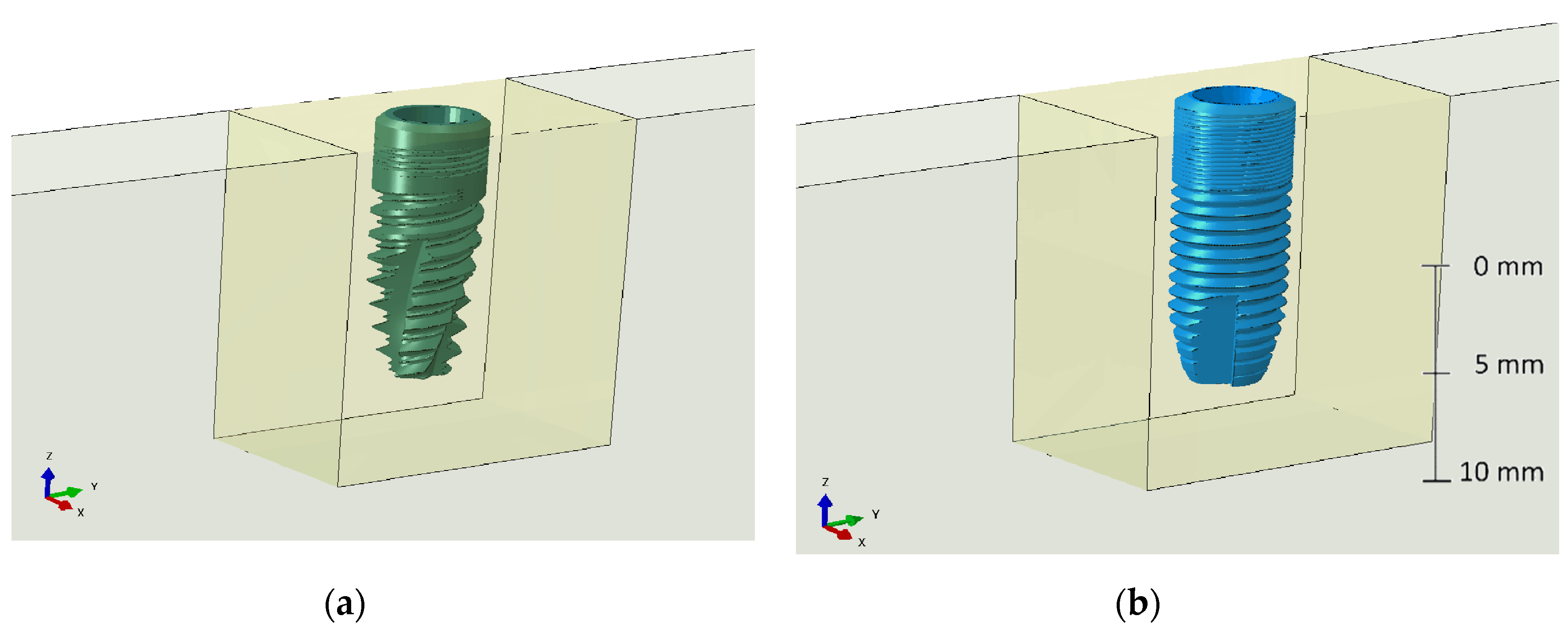
2.1. Dental Implants

In order to develop this study, our group used two 4 mm implants with 13 mm length, both with an internal connection. Described below are their main characteristics (Figure 1):
  • M-12 (Oxtein S.L., Zaragoza, Spain): Double internal hexagon conical implant, grade IV titanium and sand-blasted Large-grift Acid-etched (SLA, surface treated with argon plasma). It presents coronal microthreads, double U-threads in the middle third and minithreads in the roots which increase the contact surface with the bone.
  • ASTRA (Dentsply Sirona, Charlotte, NC, USA): Parallel wall internal double hexagon implant, grade IV titanium, surface blasted with titanium dioxide and modified with fluoride.

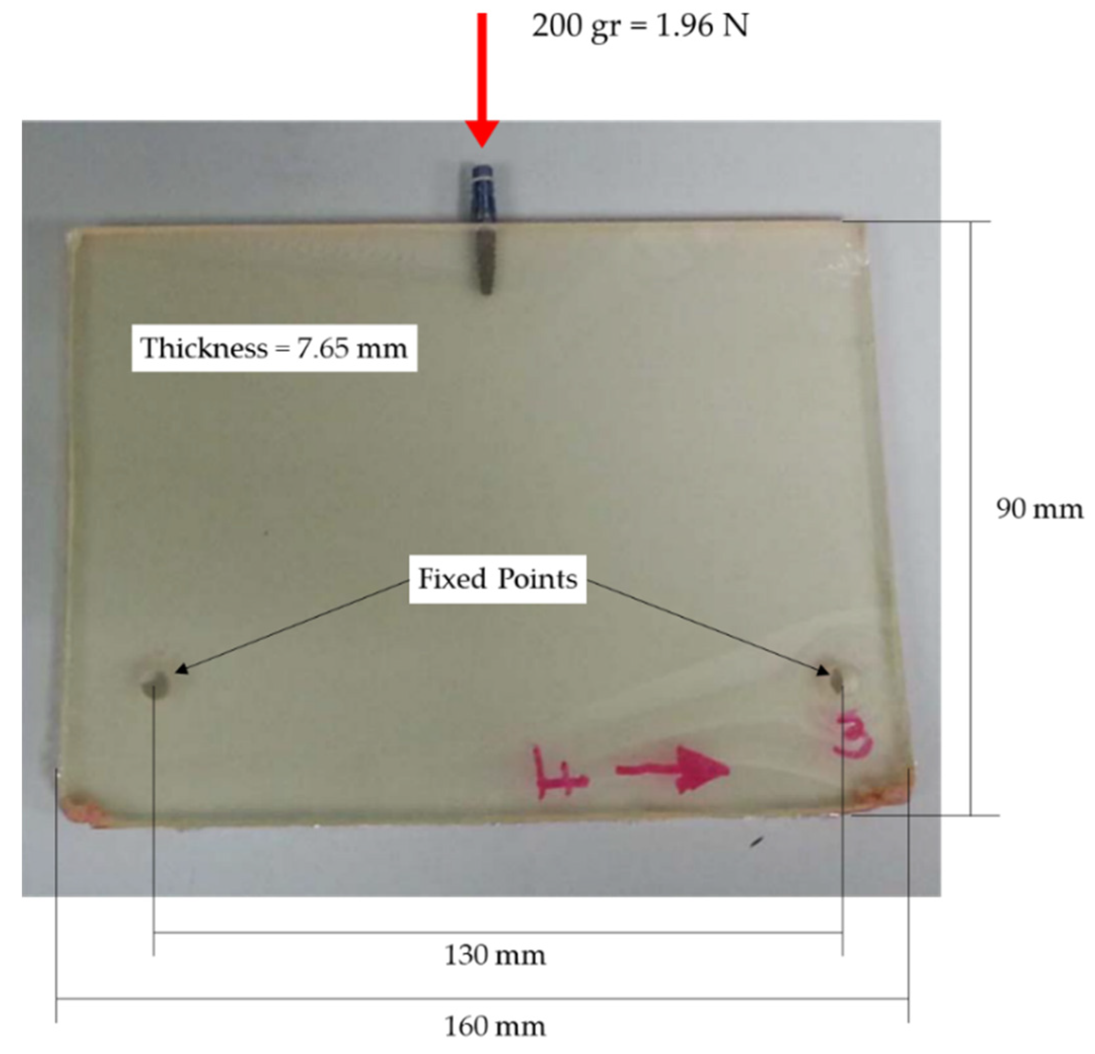
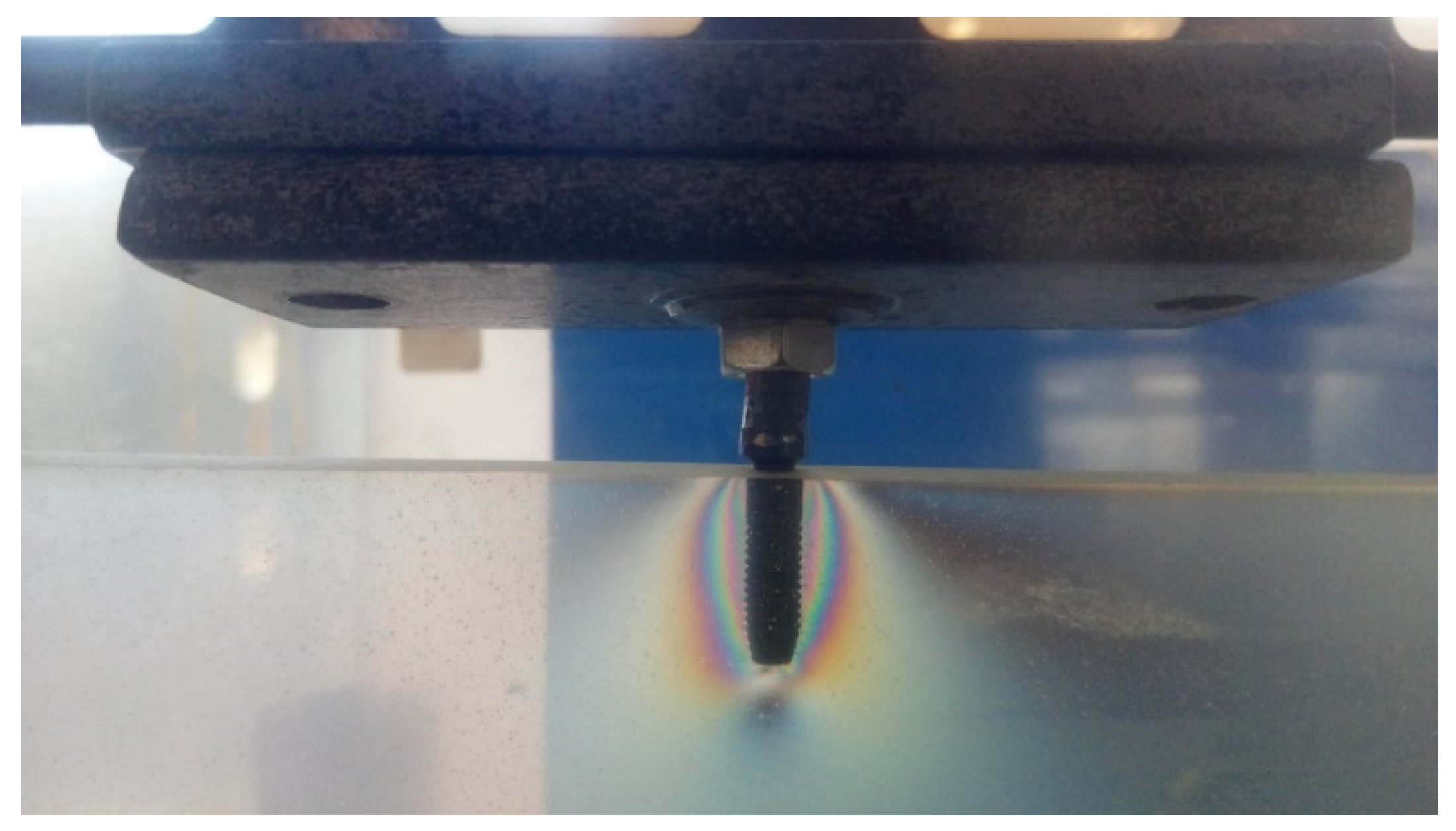
2.2. Photoelastic Models

Once the model implants for the study had been chosen, they were embedded in a polymeric material (EPOFER EX/401 epoxy resin, Feroca, S.A., Madrid, Spain) which seeks to simulate pristine bone. Both implants were subjected to photoelasticity tests after receiving loadings which will be specified later. The main characteristics of the polymer blocks are as follows (Table 1): EPOFER EX/401 epoxy resin; test tube thickness 7.65 mm; Young modulus 16,800 MPa; fringe factor 0.2; mean hot temperature 65 °C

Loadings Applied

Both implants are tested under a compression loading state of 200 g. This load has been chosen to improve the resolution of the isochromatic fringes close to the implant thread. Because the mechanical behaviour of the bone is linear under masticatory forces, results and conclusions from this study can be extrapolated to higher loads or real masticatory forces.
Figure 2 shows the geometry and load condition of the photoelastic test. To correctly load the implant in laboratory testing, a column was placed, such that the loading point was about 9.3 mm from the upper free surface of the resin plate. This column connects the implant with the weights used to define the test load (Figure 3). In turn, support for both plates was achieved by two 6 mm bolts 130 mm apart and located on a parallel line with the resin (flush with the maximum level of the implant), at a depth of 90 mm.

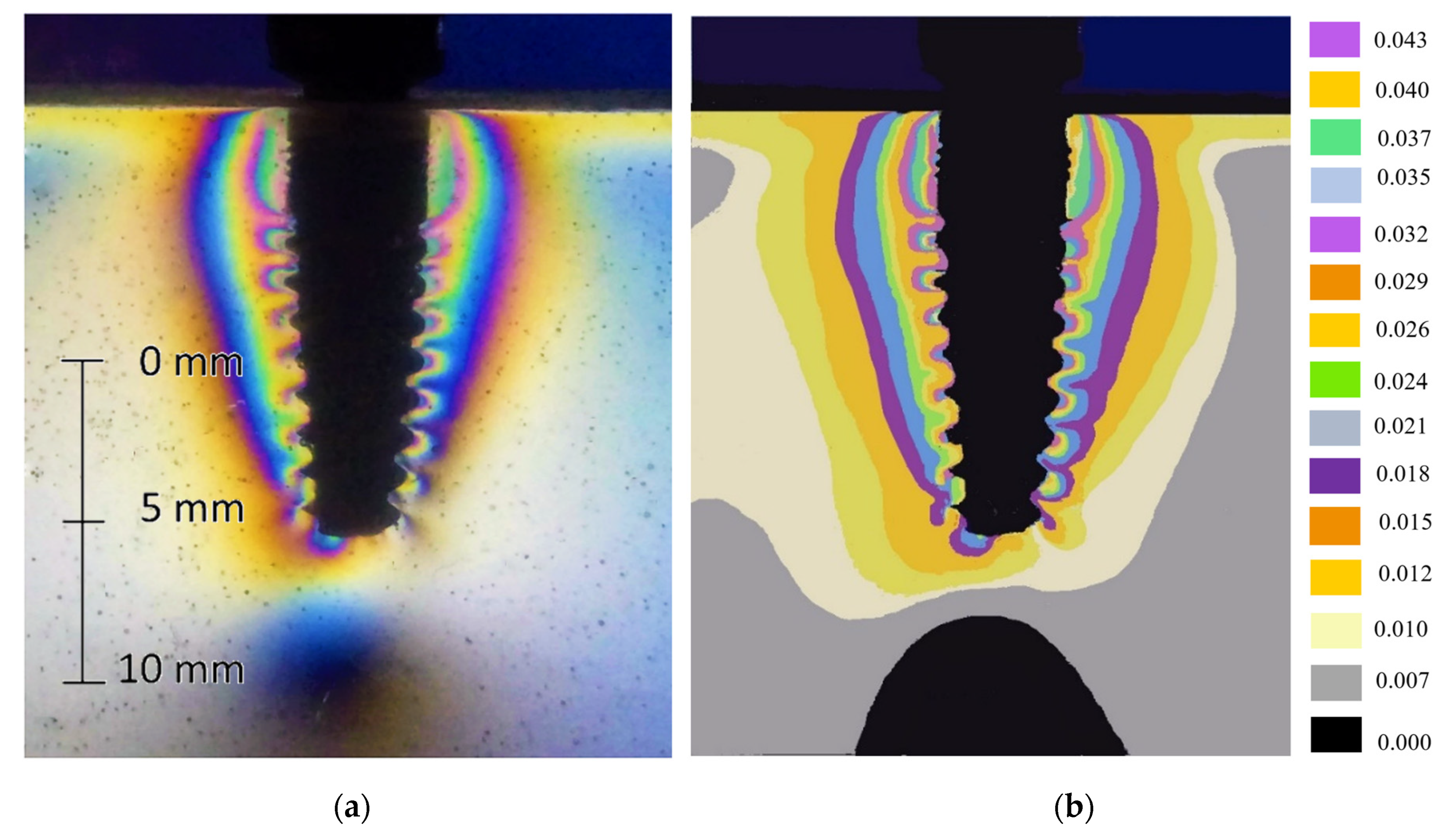
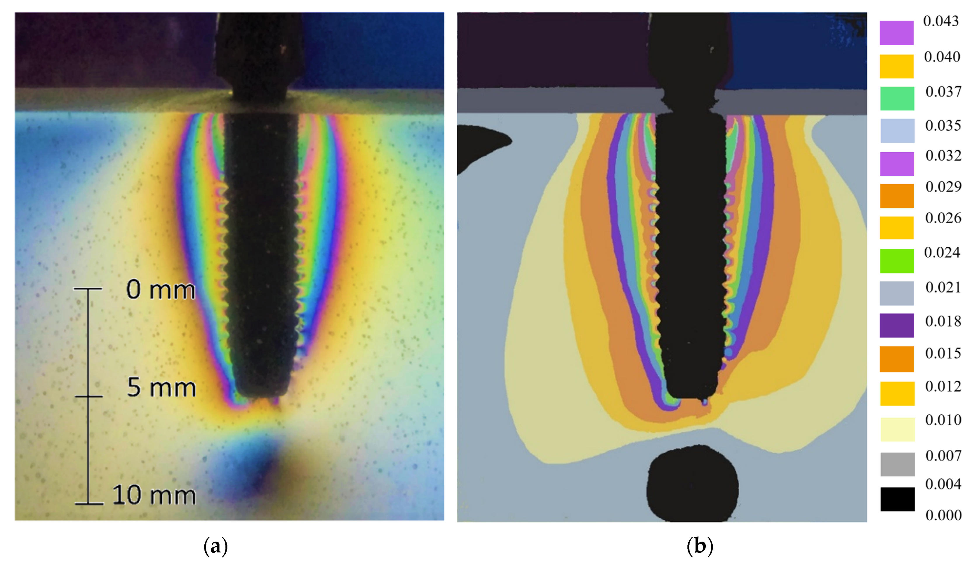
2.3. Photoelastic Analysis

Photoelasticity is a method for analysing and recording mechanical stresses on components such as test tubes or transparent plastic models, which under mechanical loading have a refractive optical effect on receiving polarized light [1,28]. Using this type of light, the stress distribution and distortion on polymeric materials on certain zones of a given structure can be studied and investigated. On applying loading as the polarized light passes through transparent material, a pattern of polarization filters is generated which allow the stress distribution to be represented in colours. Thus the concentration of forces can be ascertained in those zones with sudden geometric changes, being capable of measuring the direction and magnitude of the stress generated on the material [1,28,29,30]. This method is very helpful in implantology, providing useful information on the behaviour of implants under loadings that are similar to clinical behaviour [1,9,29]. Observation through a polarization mounting of birefringent material subjected to loading reveals the formation of colour fringe patterns associated with the main stresses on the material. In the table below is the ratio between the colours of the isochromatic fringes and the corresponding fringe order (Table 2):
The isochromatic fringes represent the place of the point of same difference of the main stresses σ1 − σ2, which is proportional to fringe order. This network of isostatics are made up of two families of orthogonal curves and shape the stress invariant which will be used in this study as an evaluation criterion. Therefore, each colour has an implicit fringe order, the null stress one being the one associated with black ((σ1 − σ2) = (n · f)/e) [31,32].
Being:
  • σ1σ2 the stress for each isochromatic fringe.
  • e the thickness of the resin plate.
  • n the fringe order.
  • f the fringe factor.
For the first part of this study, the photoelastic method was employed, where a polariscope with circular crossed polarizers (Meadowlark Optics, Inc., Frederick, CO, USA) at 90° is used. Each model was mounted in the loading frame and subjected to a compression static loading of 200 g. Subsequently, the resin temperature was increased above that of the glass transition (60 °C), until thermal homogenization was reached. Thereupon, to achieve the measurement of photoelasticity, a cross-linked polariser and a circular analyser were used, in order to obtain a network of isochromatics, by means of which it is possible to ascertain the value of the stress invariant. Finally, both heated test tubes were photographed, the distorted elastic at room temperature for the level of loading applied being negligible.

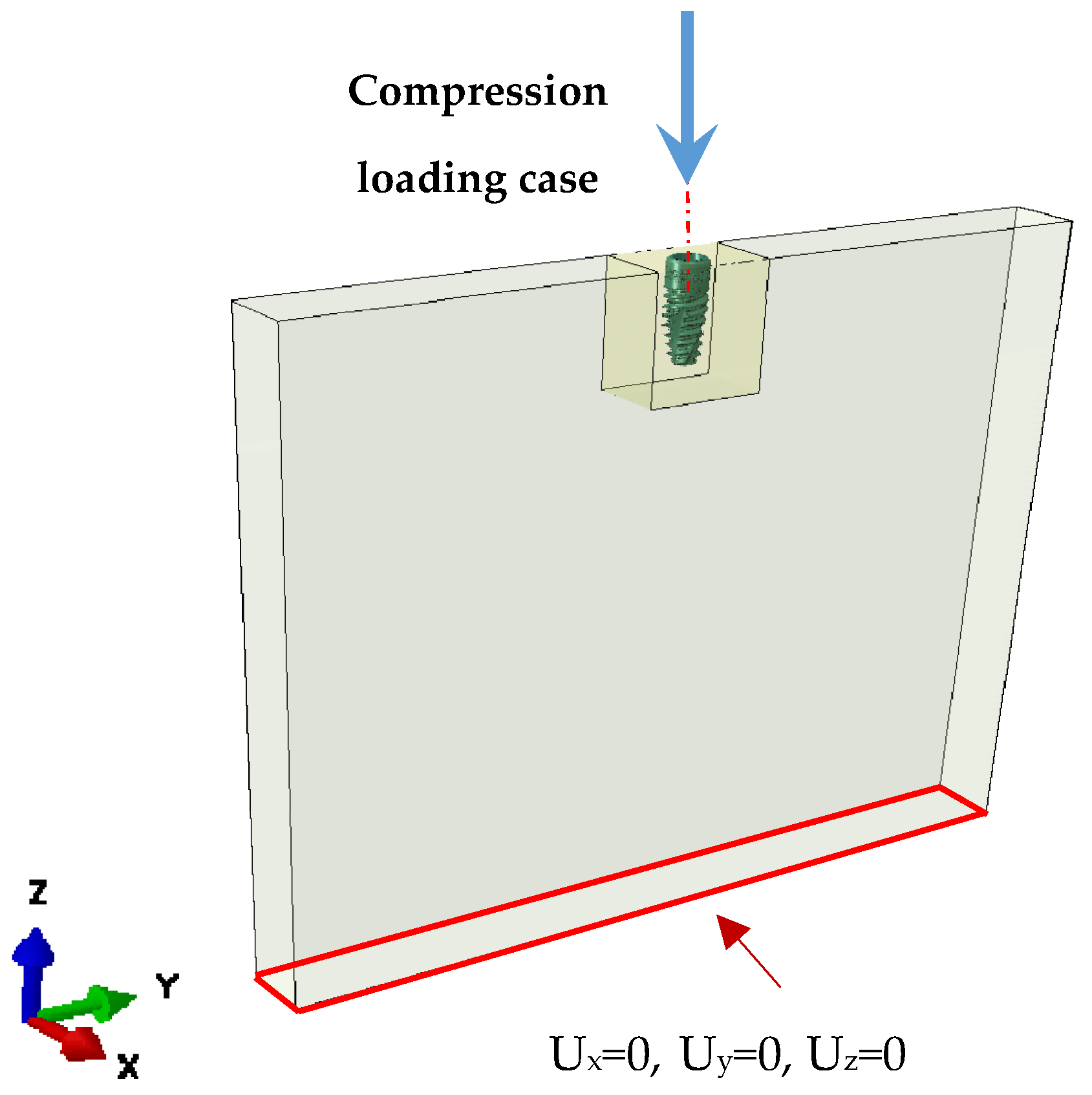
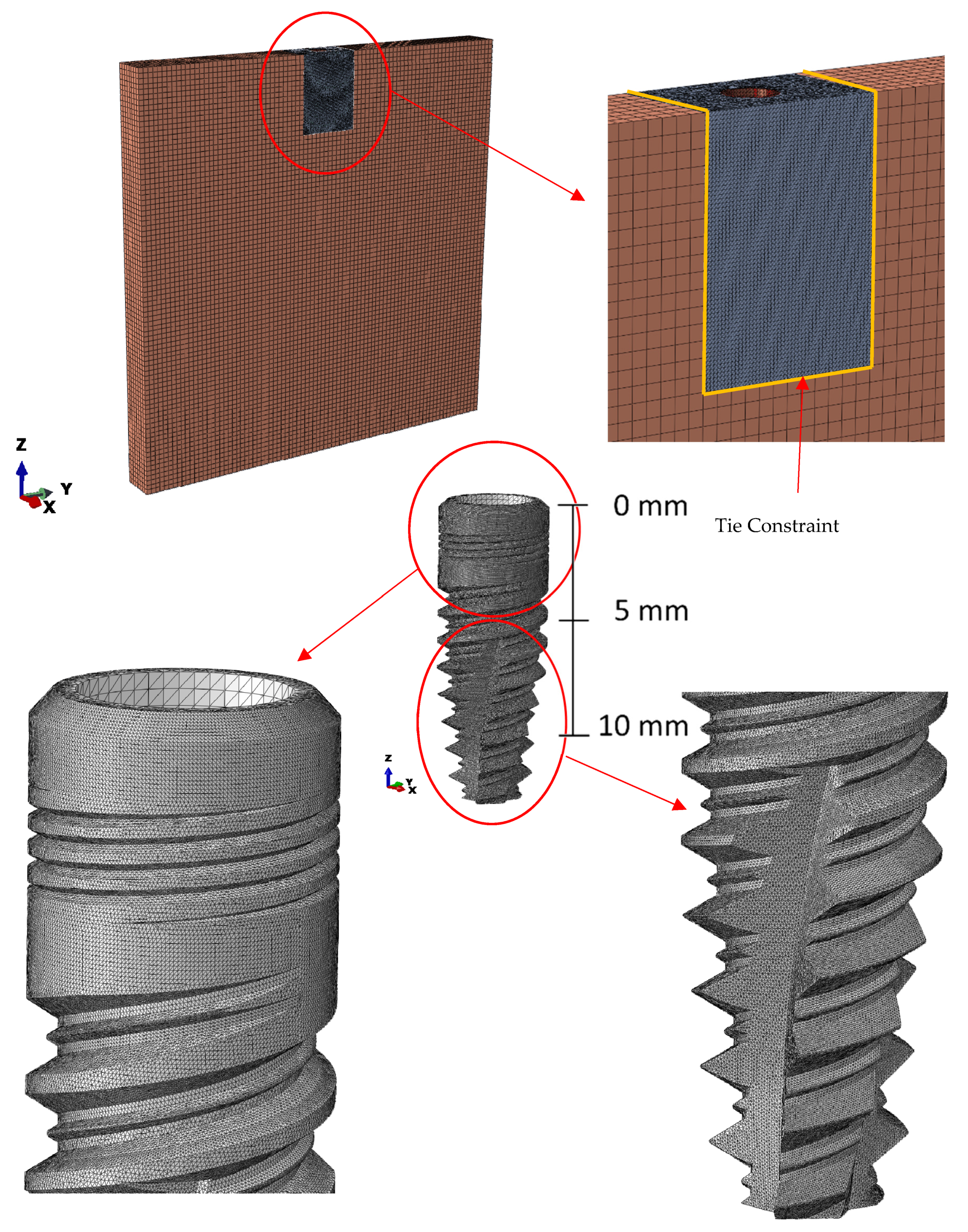
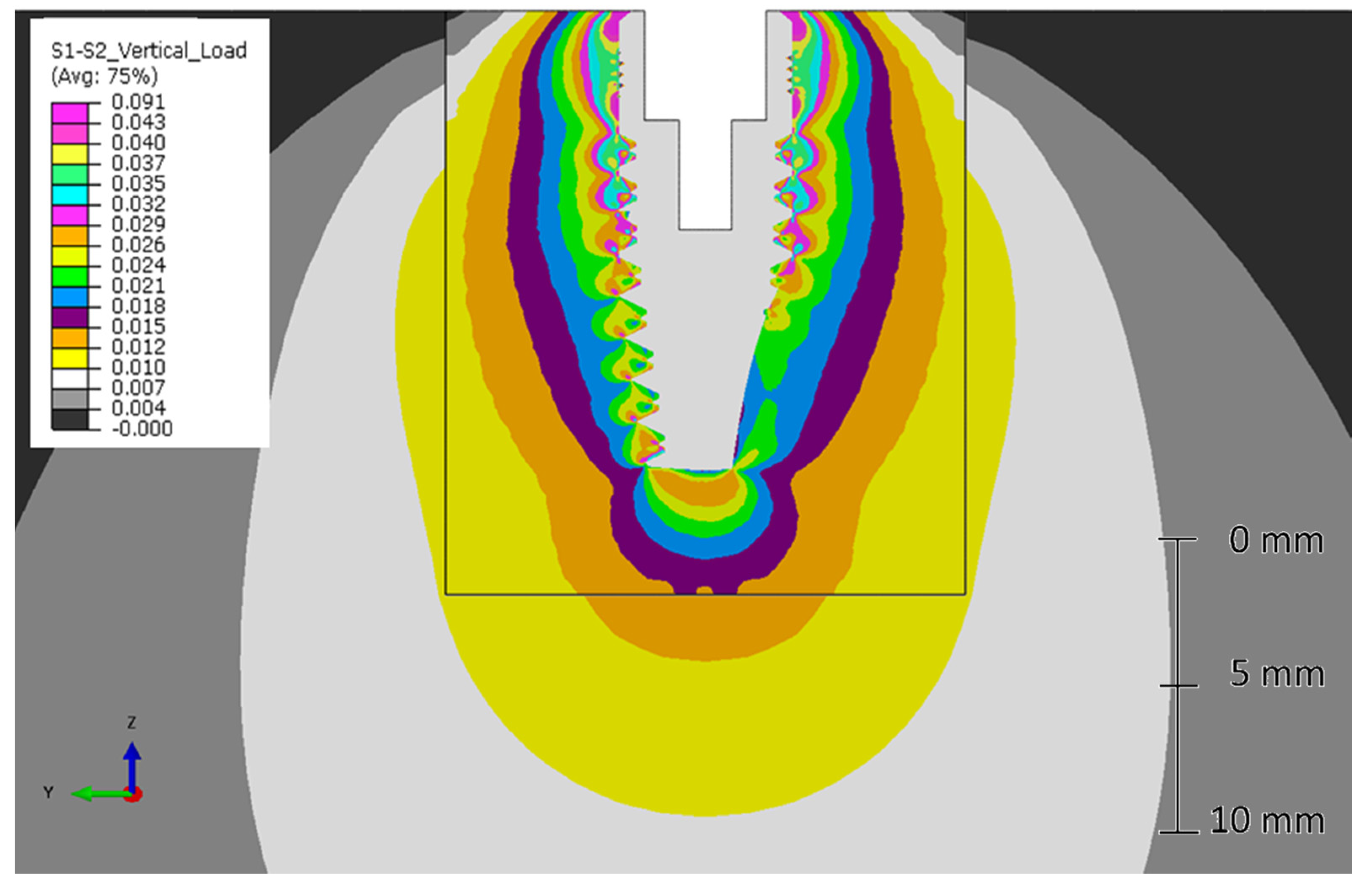
2.4. Finite Elements Analysis (FEA)

All ratio analyses have been carried out by applying finite element analysis (FEA) using the commercial Abaqus Standard 6.14.2 software package (Dassault Systèmes, Vélizy-Villacoublay, France). The mesh of the two materials has been achieved using first order tetrahedral C3D4 elements, and a isotropic elastic constitutive material model has been used for both components, resin and implant, with properties those defined in Table 1. A rigid interaction between implant and resin has been used.
For modelling the resin, two sizes of mesh have been considered, the smaller magnitude one being the one that is closer to the implant with a mean size of 0.05 mm, and the coarse mesh one being in zones furthest from the object of study, with a mean element size of 1 mm. Both partitions are joined by means of a tie constrain, which defines a kinematic constraint between the boundary nodes (Figure 4 and Figure 5). These model partitions have been defined due to computing reasons, those zones not so close to the implant being of less interest. In turn, encastre boundary conditions have been imposed on the base.
To reproduce perfect adherence between the resin and the implant, the bond between both parts has been modelled as totally binding. The loading application point has been located at 9.3 mm from the upper surface of the cortical bone and has been distributed by employing a rigid interpolation element in order to impose restrictions between the degrees of freedom of set of nodes and the movement of a rigid body, defined by a reference node.

3. Results

After applying the process described, the stress state obtained has been observed using the photoelasticity tests and the finite element model, for each of the implants being studied.
Next, the forces obtained are presented after subjecting both implants to compression loadings. In the case of the experimental tests, post-processing of said images is required in order to determine the fringe orders so that the stress map can be read and compared with the one obtained by the finite element model.
For image treatment, several digitisation techniques have been employed using mathematical algorithms. Firstly, the image has been indexed for the purpose of reducing the colour palette and discretising the RGB domain, all of this without losing important information for each of the fringe orders. Subsequently, each of them has been grouped by similarity to create each of the fringes, and finally, edge softening filters have been applied to mitigate the noise caused by indexing the image (Figure 6, Figure 7, Figure 8 and Figure 9).
In the stress state of both implants, it can be seen that the major overload occurs in the cervical zone of the implant (implant neck). The rest of the loading is distributed along the apical zone, producing a concentration of forces at each of the teeth of the thread. This effect is altered by the relief channels, which produce a localized discharge, causing the force to be redistributed, loading other zones of the implant, as happens in the low zones of the prosthesis.

4. Discussion

In this study two dental implant models under vertical loads are compared (ASTRA 4013 and M-12), using photoelasticity (Figure 6 and Figure 8) and finite elements (Figure 7 and Figure 9). Both techniques have been evaluated taking into account that the resin, which models the bone behaviour, has a slightly higher stiffness than cortical bone and D1 bone type, and significantly higher than bone types D2, D3 and D4 according to Misch’s bone mineral density classification [6]. Because the bone strength behaviour under normal loads is mainly lineal, and the stiffness ratio between the implant and the bone/resin is very high for both materials, it is expected that results can be extrapolated to real implant/bone interaction. This hypothesis should be analysed in future works.
Geremizadeh et al. [9] had already carried out a similar study in which three types of internal connection implants with different thread designs were compared. They looked at the results obtained on applying axial and oblique (25°) forces in an FEA and photoelasticity study (concordant results), recommending microthreads in the neck zone of the implants and V threads in the rest of the assembly.
In this study the same forms of stress flow in the cervical and apical zones of the implant were seen, produced by the threads of these points using both methods. However, using finite element analysis they did observe certain stress bulbs in the lower apical zones of both implants which were not perceptible in the photoelasticity tests. This is due to the loading level applied, which is adequate for correct visualization of the stress concentration in zones near the threads. To be able to perceive said force distribution in the low zone of the prosthesis, the loading level must be increased and monochromatic light used which throws up whole fringe orders. The 3D effect of adding up stresses arising from photoelasticity is not reproducible using numerical models. For this reason, a correction factor of 2 has been applied for both models (Figure 6 and Figure 8), for both the M-12 implant and the ASTRA implant, in order to establish a correlation between the stress state of the finite element model and the one obtained in the laboratory.
Due to the overlapping of forces in the photoelasticity tests, the effect that the bone extraction channels have on stress distribution cannot be appreciated, an effect which can be assessed in the numerical models and which substantially condition the mechanical behaviour of the dental prostheses [6].
Finite element analysis (FEA) is an especially effective tool for researchers. It is a non-invasive method which, by means of a computer program, is capable of recreating and analysing the biomechanics and the way in which forces affect biological systems such as dental implants. In this way, stress distribution can be checked and analysed over the geometry of the systems of interest [33,34]. These types of study have become a simple and quick means of predicting the clinical behaviour of implants once placed in the natural medium. Implants behave in a different way depending on their design and location in cortical or trabecular bone [33,35,36,37,38].
These types of study are frequent in implant analysis. Although, roughly speaking, the implants studied could present similar characteristics in trabecular and cortical bone (following the Misch classification) [39], slight differences have been detected between both implants due to their design. Whilst the ASTRA implant presents less stress on the trabecular bone, the M-12 one, on the other hand, obtained greater loading distribution on cortical bone [6].
In this study the same forms in stress flow were observed, produced by the threads in the cervical and apical zones of the implant by both methods. However, a comparison can be established between both prostheses and their behaviour under axial loadings:
The M-12 model comprises a coarse thread with a shorter length of thread in the cervical zone of the implant compared with the ASTRA model. Consequently, the fine thread with a longer length of thread in the second implant makes it acquire a greater stress bulb in the cervical zone compared with the first one. In other words, the increment of the threaded surface in the cervical zone produces higher stress concentration in the zone (M-12 implant).
In turn, the M-12 model comprises a greater thread pitch in the apical zone compared with the ASTRA model, affecting stress distribution. In this way, the lower thread pitch in the second implant makes the stresses distribute better in in the thread contact area of the apical zone, resulting in lower stress bulbs at each of them. Thus, the apical aggressiveness of the implant threads with the stress generated could be related.
This mechanical behaviour and loading distribution that has been observed in each of the implants will notably affect the stress state of the different types of bone that exist in the jaws in terms of density [6,39].
There are many studies in which implant behaviour on receiving stress is analysed using finite element analysis [6,33,35,37]. This is perhaps due to the importance of understanding the behaviour of implants in the bone. The stresses transmitted and the limits the implants withstand must be understood, given that excess stress can cause remodelling of crestal bone at the implant neck. Stresses may be distributed evenly to prevent loss of implant success [1,9,40]. It is known that cortical bone is 65% more susceptible to shearing forces [19,41].
In the studies by Pelizzer et al. [16] and Gioiato et al. [1] internal and external connection implant behaviour under oblique and axial stresses of 150 and 100 N respectively were compared. In the first of the studies a similar and symmetric stress distribution across all the implants was obtained, although they highlighted the greatest differences at the cervical and apical thirds which they attributed not only to the type of connection, but also to the shape of the threads, implant design and the presence of microthreads in the neck. In the present study, the importance of the threads at the neck in the stress transmission which implants receive has been properly corroborated. Gioiato et al. focussed on the survival of the implants on making cantilever crowns (in this case of two units) [1]. To determine the ideal length of the cantilevers many characteristics had to be analysed amongst which are to be found the number and size of the implants, the quality of surrounding bone, possible parafunctional habits of the patient, as well as distribution of the implants and the type of antagonist [1,42].
Other authors have carried out photoelastic analyses focusing solely on internal connection implants, something which, as it has already mentioned earlier, provides better results generally. Zanatta et al. concluded that the Morse connection offered better dissipation of stresses at the implant neck [19]. Some years earlier, Tonella et al. anticipated these better results of the Morse cone, although they pointed out that these results were limited to cases of unitary implants, obtaining better stress distribution with another type of internal connection in cases of bridges over three-unit implants [25]. Recent studies reported FEM-based design (optimization) of thread angle [43] for dental implant, or for hip implant [44]. In these studies, bone extracellular matrix (ECM) orientation direction as one of bone quality parameter determining bone strength mirrors FEM results (principal stress) [45].
Forces applied on the majority of implants range between 100 N and 200 N, although is known that maximum masticatory forces can reach up to 400 N [39,46].
Being able to relate the results obtained using these two methods provides us with a more reliable vision of the behaviour of these implants on natural bone. They are non-invasive analyses which help improve or update the geometric designs of dental implants.

5. Conclusions

The finite element method is a useful technique to evaluate the interaction between implant and bone from a mechanical point of view. This technique has been validated by photoelasticity test for two different implants, achieving a good correlation between both techniques, and taking into account the limitations of the photoelasticity technique, related mainly to the superimposition of the optical results through thickness for a test with a non-plane-stress condition.
Both techniques have been used to evaluate two implants with significant design differences in the implant neck and apical threads. Those differences in the design thread lead to lower stress on the trabecular bone for the ASTRA implant in comparison with the M-12 one. On the other hand, greater stress distribution on the cortical bone are obtained for the ASTRA implant in comparison with the M-12 one.

Author Contributions

Conceptualization, D.T.-L., Á.-J.M.-G. and J.-L.G.-P.; formal analysis, C.H.-G., A.P.-V. and M.-A.S.-F.; funding acquisition, D.T.-L.; investigation, C.H.-G. and A.P.-V.; methodology, D.T.-L., Á.-J.M.-G., M.-A.S.-F. and J.-L.G.-P.; project administration, M.-A.S.-F.; resources, C.H.-G.; software, Á.-J.M.-G. and A.P.-V.; supervision, E.T.-C. and J.-L.G.-P.; validation, M.-A.S.-F.; writing—original draft, C.H.-G., D.T.-L., Á.-J.M.-G., A.P.-V., E.T.-C., M.-A.S.-F. and J.-L.G.-P.; writing—review & editing, C.H.-G., D.T.-L., Á.-J.M.-G., A.P.-V., E.T.-C., M.-A.S.-F. and J.-L.G.-P. All authors have read and agreed to the published version of the manuscript.

Funding

This project was funded by Oxtein Iberia SL. (Zaragoza, Spain).

Conflicts of Interest

The authors declare no conflict of interest.

References

  1. Goiato, M.C.; Shibayama, R.; Gennari Filho, H.; de Medeiros, R.A.; Pesqueira, A.A.; dos Santos, D.M.; de Araújo, C.A. Stress distribution in implant-supported prostheses using different connection systems and cantilever lengths: Digital photoelasticity. J. Med. Eng. Technol. 2016, 40, 35–42. [Google Scholar] [CrossRef] [PubMed]
  2. Lin, D.; Li, Q.; Li, W.; Duckmanton, N.; Swain, M. Mandibular bone remodeling induced by dental implant. J. Biomech. 2010, 43, 287–293. [Google Scholar] [CrossRef] [PubMed]
  3. Gaviria, L.; Salcido, J.P.; Guda, T.; Ong, J.L. Current trends in dental implants. J. Korean Assoc. Oral Maxillofac. Surg. 2014, 40, 50–60. [Google Scholar] [CrossRef] [PubMed]
  4. Las Casas, E.B.; Ferreira, P.C.; Cimini, C.A., Jr.; Toledo, E.M.; Barra, L.P.; Cruz, M. Comparative 3D finite element stress analysis of straight and angled wedge-shaped implant design. Int. J. Oral Maxillofac. Implant. 2008, 23, 215–222. [Google Scholar]
  5. Coray, R.; Zeltner, M.; Özcan, M. Fracture strength of implant abutments after fatigue testing: A systematic review and a meta-analysis. J. Mech. Behav. Biomed. Mater. 2016, 62, 333–346. [Google Scholar] [CrossRef]
  6. Azcarate-Velázquez, F.; Castillo-Oyagüe, R.; Oliveros-López, L.G.; Torres-Lagares, D.; Martínez-González, Á.J.; Pérez-Velasco, A.; Lynch, C.D.; Gutiérrez-Pérez, J.L.; Serrera-Figallo, M.Á. Influence of bone quality on the mechanical interaction between implant and bone: A finite element analysis. J. Dent. 2019, 88, 103161. [Google Scholar] [CrossRef]
  7. Khorshid, H.E.; Hamed, H.A.; Aziz, E.A. Complications, risk factors, and failures of immediate functional loading of implants placed in the completely edentulous maxillae: A report of 3 consecutive cases. Implant Dent. 2014, 23, 125–131. [Google Scholar] [CrossRef]
  8. Marcián, P.; Zikmund, T.; Kaiser, J.; Borák, L.; Wolff, J.; Horáčková, L. Micro finite element analysis of dental implants under different loading conditions. Comput. Biol. Med. 2018, 96, 157–165. [Google Scholar] [CrossRef]
  9. Geramizadeh, M.; Katoozian, H.; Amid, R.; Kadkhodazadeh, M. Comparison of finite element results with photoelastic stress analysis around dental implants with different threads. Dent. Med. Probl. 2018, 55, 17–22. [Google Scholar] [CrossRef] [Green Version]
  10. Abduo, J.; Bennani, V.; Waddell, N.; Lyons, K.; Swain, M. Assessing the fit of implant fixed prostheses: A critical review. Int. J. Oral Maxillofac. Implant. 2010, 25, 506–515. [Google Scholar]
  11. Marcián, P.; Borák, L.; Valášek, J.; Kaiser, J.; Florian, Z.; Wolff, J. Finite element analysis of dental implant loading on atrophic and non-atrophic cancellous andcortical mandibular bone—A feasibility study. J. Biomech. 2014, 47, 3830–3836. [Google Scholar] [CrossRef] [PubMed]
  12. Serino, G.; Turri, A. Extent and location of bone loss at dental implants in patients with peri-implantitis. J. Biomech. 2011, 44, 267–271. [Google Scholar] [CrossRef] [PubMed]
  13. Lee, J.I.; Lee, Y.; Kim, N.Y.; Kim, Y.L.; Cho, H.W. A photoelastic stress analysis of screw- and cement-retained implant prostheses with marginal gaps. Clin. Implant. Dent. Relat. Res. 2013, 15, 735–749. [Google Scholar] [CrossRef] [PubMed]
  14. Lekholm, U.; Adell, R.; Brånemark, P.-I. Complications. In Tissue Integrated Prostheses: Osseointegration in Clinical Dentistry; Brånemark, P.-I., Zarb, G.A., Albrektsson, T., Eds.; Quintessence, Pubishing, Co.: Chicago, IL, USA, 1985; pp. 233–240. [Google Scholar]
  15. Assif, D.; Marshak, B.; Schmidt, A. Accuracy of implant impression techniques. Int. J. Oral. Maxillofac. Implants. 1996, 11, 216–222. [Google Scholar] [CrossRef]
  16. Pellizzer, E.P.; Carli, R.I.; Falcón-Antenucci, R.M.; Verri, F.R.; Goiato, M.C.; Villa, L.M. Photoelastic analysis of stress distribution with different implant systems. J. Oral. Implantol. 2014, 40, 117–122. [Google Scholar] [CrossRef]
  17. Brunski, J.B. In vivo bone response to biomechanical loading at the bone dental-implant interface. Adv. Dent. Res. 1999, 13, 99–119. [Google Scholar] [CrossRef]
  18. Kasemo, B.; Lausmaa, J. Biomaterial and implant surfaces: A surface science approach. Int. J. Oral Maxillofac. Implants. 1988, 3, 247–259. [Google Scholar]
  19. Zanatta, L.C.; Dib, L.L.; Gehrke, S.A. Photoelastic stress analysis surrounding different implant designs under simulated static loading. J. Craniofac. Surg. 2014, 25, 1068–1071. [Google Scholar] [CrossRef]
  20. Baggi, L.; Cappelloni, I.; Di Girolamo, M.; Maceri, F.; Vairo, G. The influence of implant diameter and length on stress distribution of osseointegrated implants related to crestal bone geometry: A three-dimensional finite element analysis. J. Prosthet. Dent. 2008, 100, 422–431. [Google Scholar] [CrossRef] [Green Version]
  21. Misch, C.E.; Strong, T. Scientific rationale for dental implant design. In Contemporary Implant Dentistry; Misch, C.E., Ed.; Elsevier: St. Louis, MO, USA, 1999; pp. 200–229. [Google Scholar]
  22. Chun, H.J.; Cheong, S.Y.; Han, J.H.; Heo, S.J.; Chung, J.P.; Rhyu, I.C.; Choi, Y.C.; Baik, H.K.; Ku, Y.; Kim, M.H. Evaluation of design parameters of osseointegrated dental implants using finite element analysis. J. Oral Rehabil. 2002, 29, 565–574. [Google Scholar] [CrossRef]
  23. Abususse, N.H.; Pagni, G.; Rebaudi, A.; Wang, H.-L. The effect of thread pattern implant osseointegration. Clin. Oral Implants Res. 2009, 21, 129–136. [Google Scholar]
  24. Barbier, L.; Schepers, E. Adaptive bone remodeling around oral implants under axial and nonaxial loading conditions in the dog mandible. Int. J. Oral Maxillofac. Implants. 1997, 12, 215–223. [Google Scholar] [PubMed]
  25. Tonella, B.P.; Pellizzer, E.P.; Falcón-Antenucci, R.M.; Ferraço, R.; de Faria Almeida, D.A. Photoelastic analysis of biomechanical behavior of single and multiple fixed partial prostheses with different prosthetic connections. J. Craniofac. Surg. 2011, 22, 2060–2263. [Google Scholar] [CrossRef] [PubMed]
  26. Balfour, A.; O’Brien, G. Comparative study of antirotational single tooth abutments. J. Prosthet. Dent. 1995, 73, 36–43. [Google Scholar] [CrossRef]
  27. Çehreli, M.; Duyck, J.; De Cooman, M.; Puers, R.; Naert, I. Implant design and interface force transfer. A photoelastic and strain-gauge analysis. Clin. Oral Implants Res. 2004, 15, 249–257. [Google Scholar] [CrossRef] [PubMed]
  28. Goiato, M.C.; Tonella, B.P.; do Prado Ribeiro, P.; Pellizzer, E.P. Methods used for assessing stresses in buccomaxillary prostheses: Photoelasticity, finite element technique, and extensometry. J. Craniofac. Surg. 2009, 20, 561–564. [Google Scholar] [CrossRef]
  29. Shinde, S.B.; Hirmukhe, S.S.; Dhatrak, P.N. Photoelastic stress analysis: A review. In Proceedings of the 5th National Conference RDME, Pune, India, 10–11 March 2016. [Google Scholar]
  30. Philips, J.W. Experimental Stress Analysis, 2nd ed.; Board of Trustees at University of Illinois: Urbana, IL, USA, 1998. [Google Scholar]
  31. Muñiz, C.; Castillo, W. Ensayos de Fotoelasticidad en Probetas de Metacrilato; Facultad de Ciencias, Tecnología y Ambiente, Universidad Centroamericana: Manuagua, Nicaragua, 2010. [Google Scholar]
  32. Vitantonio, E.M.; Reynoso, A.C.; Rasia, R.J. Análisis Experimental de Tensiones en Piezas Dentarias con Diversas Preparaciones y Desgastes; Facultad de Odontología, Universidad Nacional del Rosario: Rosario, Argentina, 2003. [Google Scholar]
  33. Raaj, G.; Manimaran, P.; Kumar, C.D.; Sadan, D.S.; Abirami, M. Comparative Evaluation of Implant Designs: Influence of Diameter, Length, and Taper on Stress and Strain in the Mandibular Segment-A Three-Dimensional Finite Element Analysis. J. Pharm. Bioallied. Sci. 2019, 11 (Suppl. 2), S347–S354. [Google Scholar]
  34. Rees, J.S. An investigation into the importance of the periodontal ligament and alveolar bone as supporting structures in finite element studies. J. Oral Rehabil. 2001, 28, 425–432. [Google Scholar] [CrossRef]
  35. Geramizadeh, M.; Katoozian, H.; Amid, R.; Kadkhodazadeh, M. Three-dimensional optimization and sensitivity analysis of dental implant thread parameters using finite element analysis. J. Korean Assoc. Oral Maxillofac. Surg. 2018, 44, 59–65. [Google Scholar] [CrossRef] [Green Version]
  36. Gosavi, S.P.; Dhatrak, P.N.; Narkar, K.M. Optimisation of dental implant. Int. Eng. Res. J. 2015, 3, 4319–4323. [Google Scholar]
  37. Pirjamalineisiani, A.; Sarafbidabad, M.; Jamshidi, N.; Esfahani, F.A. Finite element analysis of post dental implant fixation in drilled mandible sites. Comput. Biol. Med. 2017, 81, 159–166. [Google Scholar] [CrossRef] [PubMed]
  38. Geng, J.P.; Tan, K.B.; Liu, G.R. Application of finite element analysis in implant dentistry: A review of the literature. J. Prosthet. Dent. 2001, 85, 585–598. [Google Scholar] [CrossRef] [PubMed] [Green Version]
  39. Misch, C.E. Dental Implant Prosthetics, 2nd ed.; Mosby: St. Louis, MO, USA, 2015. [Google Scholar]
  40. Alkan, I.; Sertgöz, A.; Ekici, B. Influence of occlusal forces on stress distribution in preloaded dental implant screws. J. Prosth. Dent. 2004, 91, 319–325. [Google Scholar] [CrossRef] [PubMed]
  41. Guo, E. Mechanical properties of cortical and cancellous bone tissue. In Bone Mechanics Handbook, 2nd ed.; Cowin, S.C., Ed.; CRC Press: Boca Raton, FL, USA, 2001; pp. 1–23. [Google Scholar]
  42. Rangert, B.; Jemt, T.; Jörneus, L. Forces and moments on Branemark implants. Int. J. Oral Maxillofac. Implant. 1989, 4, 241–247. [Google Scholar]
  43. Kuroshima, S.; Nakano, T.; Ishimoto, T.; Sasaki, M.; Inoue, M.; Yasutake, M.; Sawase, T. Optimally oriented grooves on dental implants improve bone quality around implants under repetitive mechanical loading. Acta Biomater. 2017, 48, 433–444. [Google Scholar] [CrossRef] [Green Version]
  44. Noyama, Y.; Nakano, T.; Ishimoto, T.; Sakai, T.; Yoshikawa, H. Design and optimization of the oriented groove on the hip implant surface to promote bone microstructure integrity. Bone 2013, 52, 659–667. [Google Scholar] [CrossRef]
  45. Ishimoto, T.; Nakano, T.; Umakoshi, Y.; Yamamoto, M.; Tabata, Y. Degree of biological apatite c-axis orientation rather than bone mineral density controls mechanical function in bone regenerated using rBMP-2. J. Bone Miner. Res. 2013, 28, 1170–1179. [Google Scholar] [CrossRef]
  46. Cicciù, M.; Cervino, G.; Bramanti, E.; Lauritano, F.; Lo Gudice, G.; Scappaticci, L.; Rapparini, A.; Guglielmino, E.; Risitano, G. FEM analysis of mandibular prosthetic overdenture supported by dental implants: Evaluation of different retention methods. Comput. Math. Methods Med. 2015, 2015, 943839. [Google Scholar] [CrossRef] [Green Version]
Figure 1. Detailed representation of the view of the implants used in the study (a) M-12 implant; (b) ASTRA 4013 implant.
Metals 10 00648 g001
Figure 2. Photoelastic Test. Geometry, boundary conditions and load.
Metals 10 00648 g002
Figure 3. Photoelastic test. General view.
Metals 10 00648 g003
Figure 4. Boundary conditions and loading states for the M-12 implant model.
Metals 10 00648 g004
Figure 5. Mesh for the M-12 implant model.
Metals 10 00648 g005
Figure 6. (σ1 − σ2) Stress map, [MPa], for M-12 implant subjected to axial loading, obtained using photoelasticity. (a) Real test image; (b) digitised image with factorised scale.
Metals 10 00648 g006
Figure 7. (σ1 − σ2) Stress map, [MPa], for M-12 implant subjected to axial loading, obtained using Finite Element Analysis. Peak stress of 0.091 MPa located in the interaction between the implant and the resin in the upper free surface zone has been suppressed, because it is considered as non-representative and derived from finite element modelling and singularities.
Metals 10 00648 g007
Figure 8. (σ1 − σ2) Stress map, [MPa], for ASTRA implant subjected to axial loading, obtained using photoelasticity. (a) Real test image; (b) Digitised image with factorised scale.
Metals 10 00648 g008
Figure 9. (σ1 − σ2) Stress map, [MPa], for ASTRA implant subjected to axial loading, obtained using Finite Element Analysis. Peak stress of 0.071 MPa located in the interaction between the implant and the resin in the upper free surface zone has been suppressed because it is considered as non-representative and derived from finite element modelling and singularities.
Metals 10 00648 g009
Table 1. Representative table of baseline data employed in the numerical models of the blocks and dental implants.
Data Employed in the Numerical Models Young Modulus (GPa)Poisson’s Ratio
Implants110.00.3
Resin16.80.4
Table 2. Sequence of the chromatic map in elasticity tests and associated fringe order.
ColourFringe OrderColourFringe Order
Black0Blue2.2
Grey0.28Green2.4
White0.45Yellow2.7
Yellow0.6Pink3
Orange0.8Blue3.1
Purple1Green3.3
Blue1.08Yellow3.7
Green1.22Pink4
Yellow1.39Green4.3
Orange1.63Yellow4.7
Pink2Pink5

