Mathematical Approach to Improve the Thermoeconomics of a Humidification Dehumidification Solar Desalination System


1
Facultad de Ingeniería, Universidad Autónoma de Yucatán, Av. Industrias No Contaminantes por Anillo Periférico Norte, Apdo. Postal 150, Cordemex, Mérida 97310, Yucatán, Mexico
2
Ingeniería Eléctrica-Maestría en Tecnologías de la Información, Tecnológico Nacional de México/Instituto Tecnológico Superior de Huauchinango, Av. Tecnológico No. 80, Col. 5 de Octubre, Huauchinango 73173, Puebla, Mexico
3
Department of Mechanical Engineering, Faculty of Engineering and Technology, International Islamic University, Islamabad 44000, Pakistan
4
Programa de Maestría y Doctorado en Ingeniería, Especialidad en Sistemas Eléctricos de Potencia, Universidad Nacional Autónoma de México, Ciudad de México 04510, Mexico
*
Author to whom correspondence should be addressed.
Mathematics 2021, 9(1), 33; https://doi.org/10.3390/math9010033
Submission received: 24 June 2020
/
Revised: 5 October 2020
/
Accepted: 15 October 2020
/
Published: 25 December 2020
(This article belongs to the Special Issue Applications of Mathematical Models in Engineering)
Abstract
:Water desalination presents a need to address the growing water-energy nexus. In this work, a literature survey is carried out, along an application of a mathematical model is presented to enhance the freshwater productivity rate of a solar-assisted humidification-dehumidification (HDH) type of desalination system. The prime novelty of this work is to recover the waste heat by reusing the feedwater at the exit of the condenser in the brackish water storage tank and to carry out the analysis of its effectiveness in terms of the system’s yearly thermoeconomics. The developed mathematical model for each of the components of the plant is solved through an iterative procedure. In a parametric study, the influence of mass flow rates (MFRs) of inlet air, saline water, feedwater, and air temperature on the freshwater productivity is shown with and without the waste heat recovery from the condensing coil. It is reported that the production rate of water is increased to a maximum of 15% by recovering the waste heat. Furthermore, yearly analysis has shown that the production rate of water is increased to a maximum of 16% for June in the location of Taxila, Pakistan. An analysis is also carried out on the economics of the proposed modification, which shows that the cost per litre of the desalinated water is reduced by ~13%. It is concluded that the water productivity of an HDH solar desalination plant can be significantly increased by recovering the waste heat from the condensing coil.
1. Introduction
Water covers almost 71% of the total Earth’s surface [1]. Sea contains 97% of the total water of the Earth [2] and the remaining 3% is stored in the form of rivers, glaciers, underground water storage, and lakes, etc. The freshwater is not evenly distributed in the world, as some geography near the equator has less availability of freshwater. The seawater contains a large number of salts. Therefore, it is not feasible to be used for household, agricultural, or commercial purposes [3]. Considering this aspect, desalination is an important need of the human being. In this regard, Manju et al. [4] provided an extensive review of the need for a desalination system to overcome future freshwater demand for India. Among many desalination processes [5], some can be energy inefficient, costly, and/or can have environmental impacts (CO2 emissions and other dangerous byproducts as referenced by [6]) depending on the design parameters [7].
The use of solar radiation is undergoing intensive research for the desalination process [5] since solar energy is a low-grade heat source considering the exergetic usefulness [8]. In this aspect, Reif et al. [9] focused on the desalination system powered by solar energy and reviewed its potential and challenges. Considering the need of the modern world, Giwa et al. [10] proposed recent advances in the solar-assisted humidification-dehumidification (HDH) type desalination system in terms of improved design and productivity. Afterwards, Kabeel et al. [11] and Hamed et al. [12] developed an experimental setup for the solar power HDH type of desalination system. Kabeel et al. [11] concluded that the condenser with a cylindrical shell and corrugated fins led to an increase in the rate of heat transfer, the cellulose of 5 mm gives higher productivity as compared to the usage of cellulose of 7 mm under both natural and forced flow circulation. Whereas, Hamed et al. [12] concluded that average productivity of the desalination unit is 22 litres per day with an estimated cost of 0.0578 USD per litre, the best operating time during the day is between 1 and 5 pm, and the productivity of the unit increases as the temperature of the water which is entering the humidifier is increased. Balaji et al. [13] carried out the numerical analysis of HDH desalination system by developing code in ‘C’ language to study the performance for various operating conditions. Their results have indicated that increasing the mass flow rate of air increases the gain-output-ratio and they reported that the economic feasibility of the system is in the lower range because no external sources were used.
Zhani et al. [14] also developed a prototype of a solar-assisted HDH desalination system and tested it for the weather conditions of Tunisia during the summer season (June, July, and August). They concluded that their proposed system is quite efficient technically, however it lacks in economic efficiency. Owing to the requirement of a large surface area for solar energy collection, Elminshawy et al. [15] proposed to run the desalination system using two energy sources i.e., solar as well as a low-grade heat source. Elminshawy et al. [15] also developed an analytical model and the results were compared with the experimental results. It was concluded that the cost of the water is 0.014 USD per litre, and this corresponds to a fuel-saving equivalent to 1844 kg per hour.
Narayan et al. [16] evaluated the potential of a solar-driven humidification-dehumidification desalination plant for small-scale decentralized water production, presented [17] the thermodynamic analysis of desalination cycles, introduced [18] an experimental investigation on the thermal design of humidification dehumidification desalination system, and also presented [19] a thermodynamic balancing of HDH desalination by mass extraction and injection. The authors, in their reference work [17], concluded that the air-heated cycles reported in the literature are insufficient, a dehumidifier is more vital than the humidifier to the performance of a conventional water-heated cycle, and the varied pressure systems can have a better performance than a single pressure system. The authors, in their reference work [18], summarized that, for a water-heated closed-air-open-water humidification, a dehumidification system without any mass extraction represents a maximum gained-output-ratio. Similarly, the authors in their reference work [19] concluded that the uncertainty of the final results with the approximation of the air being saturated to all the points in the humidification and dehumidification process seems to be reasonably small based on the boundary layer data from Thiel and Lienhard [20].
Summers et al. [21] presented a comparison of the energy efficiency of a single-stage membrane distillation desalination cycles in various configurations and reported that the rate-limiting processes and their impact on gained-output-ratio can be determined from the development model, and a single-stage vacuum membrane distillation is inherently limited by the low temperature of condensation which results from the reduction in pressure. McGovern [22] presented the performance limits of zero and single extraction humidification-dehumidification desalination systems and reported that the usage of an ideal gas model for water vapour and the air is highly accurate to model HDH systems, the influence of salinity at 35,000 parts per million is to reduce the change in moist air humidity ratio and enthalpy by approximating 1% and 3%, respectively, for a feed temperature of 25 °C and a top air temperature of 70 °C.
Mistry et al. [23] carried out an entropy generation analysis of desalination technologies, including multiple effect distillation, HDH, reverse osmosis, mechanical vapour compression, membrane distillation, and multistage flash, and also presented [24] the effect of entropy generation rate on the performance indicators, i.e., gained output ratio, of HDH desalination cycles. In summary, the authors in reference work [24] has reported that for any given cycle, there is a specific mass flow rate ratio that simultaneously minimizes the entropy generation rate and maximizes the gained-output-ratio; in other words, it corresponds that the minimization of specific irreversibility leads to peak performance.
Sharqaw et al. [25] presented the exergy calculations of seawater with applications in desalination systems and reported that the ideal mixture models give flow exergy values that are far from the actual ones and the exergetic efficiency can differ by 80% for some cases, and in another article, Sharqaw et al. [26] also presented the optimum thermal design of such desalination systems and reported that the optimum mass flow rate ratio is always greater than unity, as increasing the effectiveness of the humidifier and dehumidifier increases the recovery ratio almost linearly, and the higher maximum temperature can yield a higher gained-output-ratio.
Some authors like Khalifa et al. [27] carried out experimental and theoretical research on water desalination using a direct contact membrane distillation. The authors developed an analytical model based on heat and mass transfer equations and utilized it to predict the temperature difference across the membrane surfaces and then calculating the vapour pressure difference leading to the permeate flux. It was noted that the productivity of the system is very promising since a permeate flux of 100 kg/m2·h was achieved at 90 °C for hot feed side and 5 °C for cold side steam.
Several researchers also carried out investigations to integrate the desalination unit with thermal energy storage. In this case, Summers et al. [28] proposed the design and optimization of an air heating solar collector with phase changing material integrated with an HDH desalination plant. A two-dimensional transient finite element method was developed, and it was reported that a layer of phase-changing material of 8 cm below the absorber plate is sufficient to produce a consistent output temperature yielding a thermal efficiency of 35%. Moreover, the phase changing material can produce consistent air outlet temperature throughout the day or night.
Several other researchers integrated the desalination unit with other types of energy systems. In a work of Sulaiman et al. [29], the authors integrated the desalination plant with a parabolic trough solar air collector and evaluated two configurations of open-water open-air desalination units with collector installed before the humidifier or between the humidifier and dehumidifier. It was reported that the second configuration with the collector between the humidifier and the dehumidifier has much more advantages than the other configuration. Whereas the gained-output-ratio of the first and second configuration were 1.5 and 4.7, respectively. In a work of Lawal et al. [30], the authors integrated the HDH desalination system with a heat pump and concluded that the maximum gain-output-ratio of 8.88 and 7.63 is obtained at 80% components effectiveness using a mass flow rate ratio of 0.63 and 1.3 for modified air heated and water heated cycle, respectively.
Gabrielli and Mazzotti [31] presented a solar-driven HDH process for water desalination analyzed and optimized via an equilibrium theory and concluded it as an immediate tool for easily determining the optimal system operation. Gabra et al. [32] presented the mathematical models for the components constructed using CARNOT toolbox in a MATLAB environment and the results have shown that FOPID (fractional-proportional–integral–derivative) controlled offers a superior dynamic and static performance and reported that it can be automatically adjusted to compensate the weather changes.
As noted, significant research has been conducted on solar-assisted HDH desalination systems focusing on various design improvements with an objective to enhance the thermoeconomics of the system. One of the works in the performance and cost-effectiveness of a solar-driven humidification-dehumidification desalination system is presented by Zubair et al. [33] in which the capital cost. including supply well, equipment costs, and building costs, were considered. A multi-location (six locations in Saudi Arabia) analysis has concluded that the highest annual output is noted for Sharurah and lowest for Dhahran. Similarly, Jamil et al. [34] also reported the thermoeconomics of desalination system and concluded that the levelized cost of water production can be variable for various type of desalination system, for example, the production cost of reverse osmosis, mechanical vapour compression, multi-effect evaporation/desalination, multistage flash, and thermal vapour compression are 0.9 ± 0.3$/m3, 1.0 ± 0.5$/m3, 1.5 ± 0.5$/m3, 2.0 ± 0.5$/m3, and 2.7 ± 0.8$/m3, respectively. Likewise, Jamil et al. [34] presented that the hybrid desalination plants like energy recovery devices along with the reverse osmosis can have the lowest water production cost at 0.7 ± 0.2$/m3, leading us to the conclusion that further system improvement is needed to cope with the uncertain water security situation in the future.
One of the improvement can be related with the internal heat recovery mechanisms within the same desalination system and Xu et al. [35] has emphasized that the ongoing research on HDH desalination system has demonstrated that the internal heat recovery is a significant and potential method for improving the system performance and reducing the freshwater cost. Strictly speaking, conventionally, the HDH systems are driven by a low-grade heat source in the form of a waste heat recovery from another energy system. However, in this work, the authors are emphasizing the waste heat recovery option within the processing circuit of the desalination plant. Although, in literature, some research is available on different types of waste heat recovery procedures either with integration with another external energy resource or from an internal resource. However, this area needs more research to fully understand the potential and benefits of internal waste heat recovery.
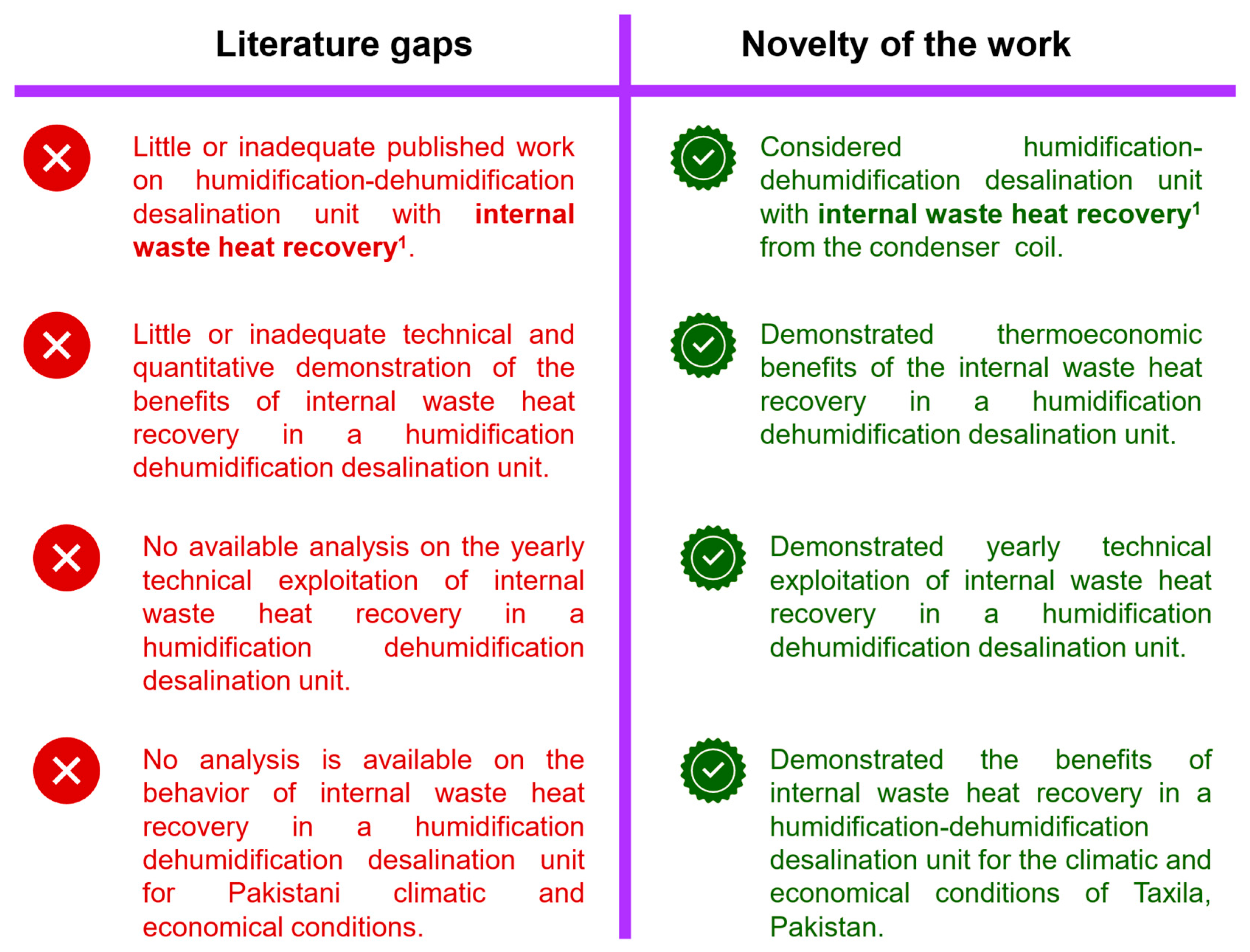
Therefore, in this work, an opportunity of waste heat recovery is identified in HDH desalination and the system behaviour is reported with and without this waste heat recovery. The waste heat is recovered from the condenser coil by supplying it back to the hot water tank. Although, a variety of research is available on different strategies and methodologies of waste heat recovery within the system and/or integration with other energy systems; nevertheless, no research is focused on the practical thermoeconomic benefits of the HDH desalination plant with waste heat recovery from the condenser coil. The summary of various waste heat recovery in desalination plants is reported in Table 1 along with the identified gaps with the literature, thus highlighting the novelty of the work. Additionally, the waste heat recovery from the system would influence the system performance. However, it would also be a subject to the local conditions, either in terms of climate to influence the thermal indicators or in terms of economic conditions to influence the levelized cost of water production. Therefore, it is very important to realize the analysis of the desalination plant considering the local climatic and economic conditions. This aspect is still missing in the literature and needs more research. Another pivot point of the analysis is that a single-day demonstration of the waste heat recovery in the desalination plant might not be enough (see Table 1 as most of the analysis is based on a selected duration), because the solar integration makes the performance transient. Therefore, a yearly analysis demonstrating the pros and cons of the internal waste heat recovery has quite a significance. Therefore, in conclusion from this discussion, and based on the identified literature gaps, there is still a need to strengthen the research area of the yearly demonstration of waste heat recovery considering the local climatic and economic conditions to fully understand the gain of the system. A checklist is included in Figure 1, highlighting various literature gaps in the literature along with the novelty of the work.
In this work, using a mathematical model and simulations for actual solar irradiance, assessment of improvements in the productivity of the proposed system is presented. The improvement in the HDH system is proposed in terms of recovering waste energy from the feed water at the exit of the dehumidification part of the system. Usually, water leaving the condenser has relatively higher enthalpy. The prime novelty of this work is to present a yearly thermoeconomic analysis of the solar-assisted humidification dehumidification desalination plant by recovering the energy from the wasted feed water enthalpy while considering the local conditions.
Here, the proposed solar-assisted HDH desalination system utilizes the feed water at the exit of the condenser/dehumidification coil by reusing it in the brackish water storage tank. This allows the waste heat recovery (WHR) for the HDH desalination system and lessens the requirement of secondary energy sources. The governing mathematical model for the flat-plate solar collector, humidification chamber, and dehumidification chamber is solved through an iterative procedure [36]. The mass and energy balance on the brackish water storage is also solved including waste heat recovery from the condensing coil. A parametric study in which the influence of mass flow rate (MFR) of inlet air, saline water, feedwater, and temperature of the air on the freshwater productivity with and without waste heat recovery is conducted. Moreover, a yearly assessment of the proposed HDH system is also carried out to study the impact of waste energy recovery. In this regard, the data of the Taxila city (Pakistan) are used for solar irradiance over the complete year. A comparison of solar-assisted HDH desalination system with and without waste heat recovery is presented for the complete year; thereby indicating the impact of energy recovery. An economic analysis is also presented to reflect the advantages of waste heat recovery in terms of the cost of the desalinated water.
2. System Description
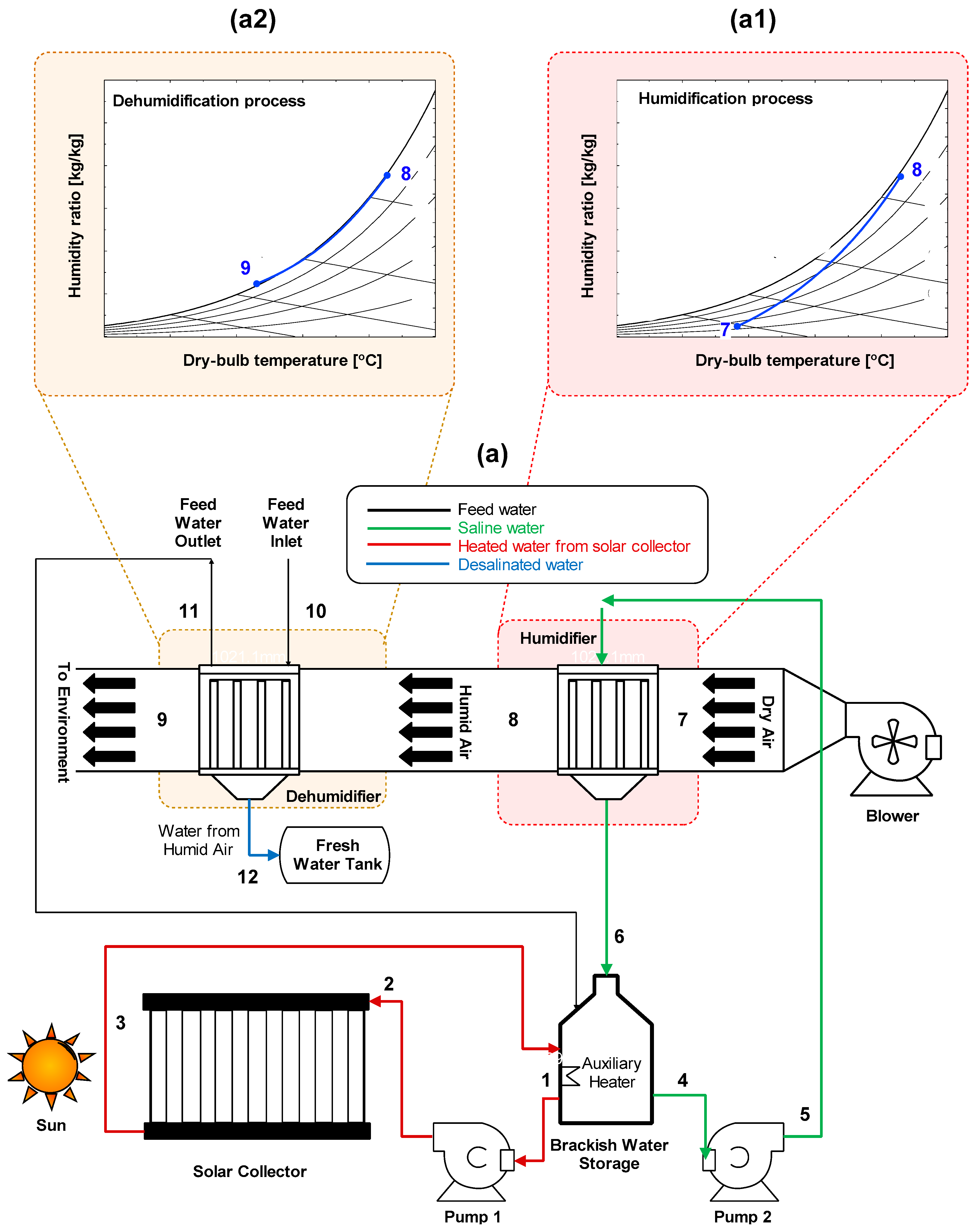
A schematic diagram of the desalination system working on humidification and dehumidification along with waste heat recovery from the condenser/dehumidification section is presented in Figure 2. Saline water is pumped into the solar collector (state 2) from brackish water storage (state 1). Water is heated in the solar collector and re-enters the heated brackish water storage at state 3.
Afterwards, the salty water is pumped to the humidification section from state 4 to 5 where it comes in direct contact with the ambient air entering at state 7. Depending on the climatic conditions, ambient air blown through the humidification chamber at state 7 where it absorbs moisture from the falling film of water. The saturated moist air leaves the humidification section at state 8, whereas the remaining salty water is re-circulated to the brackish water storage. The corresponding psychometric description of this process is presented in Figure 2a1 in which the air leaves at the saturation conditions [49].
The moist air at state 8 enters the dehumidification section where feed/cooling water is circulated at a relatively high flow rate to facilitate dehumidification. As a result, fresh condensed water is collected in a tank at state 12, and the air leaves the system to the environment. The corresponding dehumidification process is described on a psychometric chart as in Figure 2a2 [49].
The feed water at exit 11 of the dehumidification section has relatively high enthalpy because it receives heat from the humid air. In this work, the heat from this feed water is recovered by supplying it back to the brackish water storage tank.
There can be many practical ways to collect the condensed water from the dehumidification section. For instance, in other configurations of thermal desalination, Patel et al. [52] and Nayi et al. [53] have shown that an outlet pipe supported with a trough placed inside assembly of a solar still can be used and finally the condensed water can be collected in a beaker outside. In a theoretical and experimental study of seawater desalination based on humidification-dehumidification technique, Mohamed et al. [54] have demonstrated that the freshwater can be collected at the bottom of the condensation coil for a vertical section. In another work, Rajaseenivasan et al. [55] presented an experimentally verified HDH system with a dual-purpose collector and employed a horizontal flow shell-and-tube heat exchanger with the condensed water collected at the bottom from the end of the dehumidifier. Another configuration is demonstrated by Xu et al. [56] in which a novel enhanced HDH method with weakly compressed air and internal heat recovery based on traditional mechanical vapour compression is developed in which the moist air is used as a working fluid instead of a vapour. In this experimentally developed configuration [57], the freshwater is extracted from the evaporator-condenser assembly having airflow in the horizontal direction.
3. Mathematical Model
The thermal performance of the solar-assisted desalination plant is evaluated by developing a mathematical [58] expression of the components involved such as solar collector, brackish water storage, humidifier [59], and dehumidifier.
3.1. Flat Plate Solar Collector
Ioan Sarbu and Calin Sebarchievici [60] have reported that the flat-plate collectors are the heart of any solar energy collection system designed for operation in the low-temperature range (less than 60 °C) [60] or the medium temperature range (less than 100 °C) [60]. It is used to absorbed solar energy, convert it into heat, and then to transfer that heat to a stream of liquid (as in this case). They use both direct and diffuse solar radiations [60], do not require tracking of the sun [60], and require little maintenance [60]. They are mechanically simpler than concentrating collectors [60]. The major applications of these units are in solar water heating, building heating, air conditioning, and industrial process heating [60]. For quasi-steady-state conditions [61] at a given solar time, along with other standard assumptions [62,63,64], the following energy balance equation can be written
where:
The temperature of the absorber plate is calculated through an iterative method by the solution of Equations (1)–(5) coupled with:
The total absorbed solar radiation (S) is evaluated by considering the beam and diffused components of incident solar radiation along with the incorporation of optical losses (i.e., transmittance-absorptance product).
The transmittance-absorptance product is calculated separately for beam and diffused radiation.
Fresnel’s expressions [61] are derived for the reflection of unpolarized radiation passing from medium 1 to medium 2 with different refractive indexes given the angle of incidence and refraction for the parallel and perpendicular components of the beam and diffused radiation. This procedure gives two Fresnel’s expressions of the beam and diffused radiation with averaged parallel and the perpendicular component of each one, and finally, it is used to calculate the transmissivity of solar radiation from the glass cover to the absorber plate.
Along with that, the incident angle for direct radiation is the angle of incidence, given by:
Afterwards, Snell’s law [61] is utilized to obtain the refractive angles from the glazing.
By taking into account the top heat loss coefficient only, the overall heat loss coefficient is computed as follows.
The bottom and side heat loss coefficients are considered negligible. Practically, it can be made possible through the usage of insulation materials which can be glass mineral roll [65], rice husk and sunflower stalks [66], petiole piece, fibres and gypsum [67], and mineral wool [68]. The convective heat transfer coefficient is calculated using [61,69]:
The method proposed in [70] is used to compute the Nusselt number between the absorber plate and the glass cover.
The radiative heat transfer coefficient is given by:
3.2. Water Storage Tank
In this research study, the feed water of the dehumidifier is being re-used in the brackish water storage, therefore, a mass and energy balance is of key importance. A mass and energy balance applied on the storage tank yields:
3.3. Humidifier
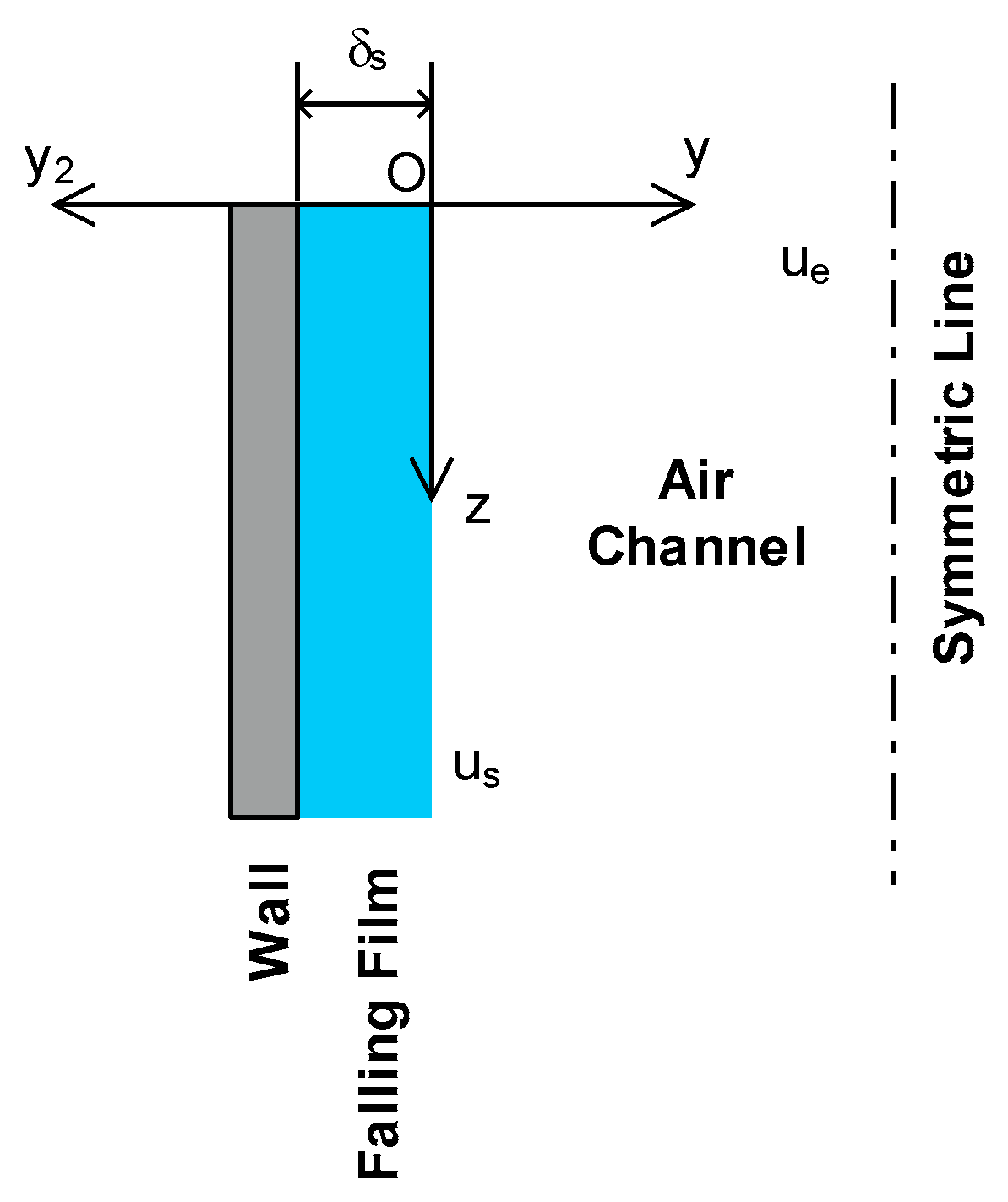
The humidification section consists of a falling film of water with accompanying airflow. It is assumed that the process is quasi-steady with negligible heat loss. The falling film is an assumed laminar with a smooth liquid-gas interface. Figure 3 shows a typical element in the humidifier section with accompanying zones. The mean velocity of a falling film is calculated using the following equation [71]:
With the thickness of the falling film, given by [72]:
![Mathematics 09 00033 i001]()

The solution of Equation (18) requires the following boundary condition [73]:
Eams [74] predicted the water evaporation rate as shown in Equation (20).
Knudson constant of evaporation [75] is written in terms of the coefficient of evaporation:
whereas the coefficient of evaporation is calculated using [74]:
Considering the evaporation affecting the heat transfer coefficient , the concept of wet bulb coefficient of heat transfer as proposed by MacLaine-Cross and Banks [76] can be used to correct the heat transfer coefficient. It can be written as:
where is derived from the wet-bulb coefficient, given by [76]:
3.4. Dehumidifier/Condenser Section
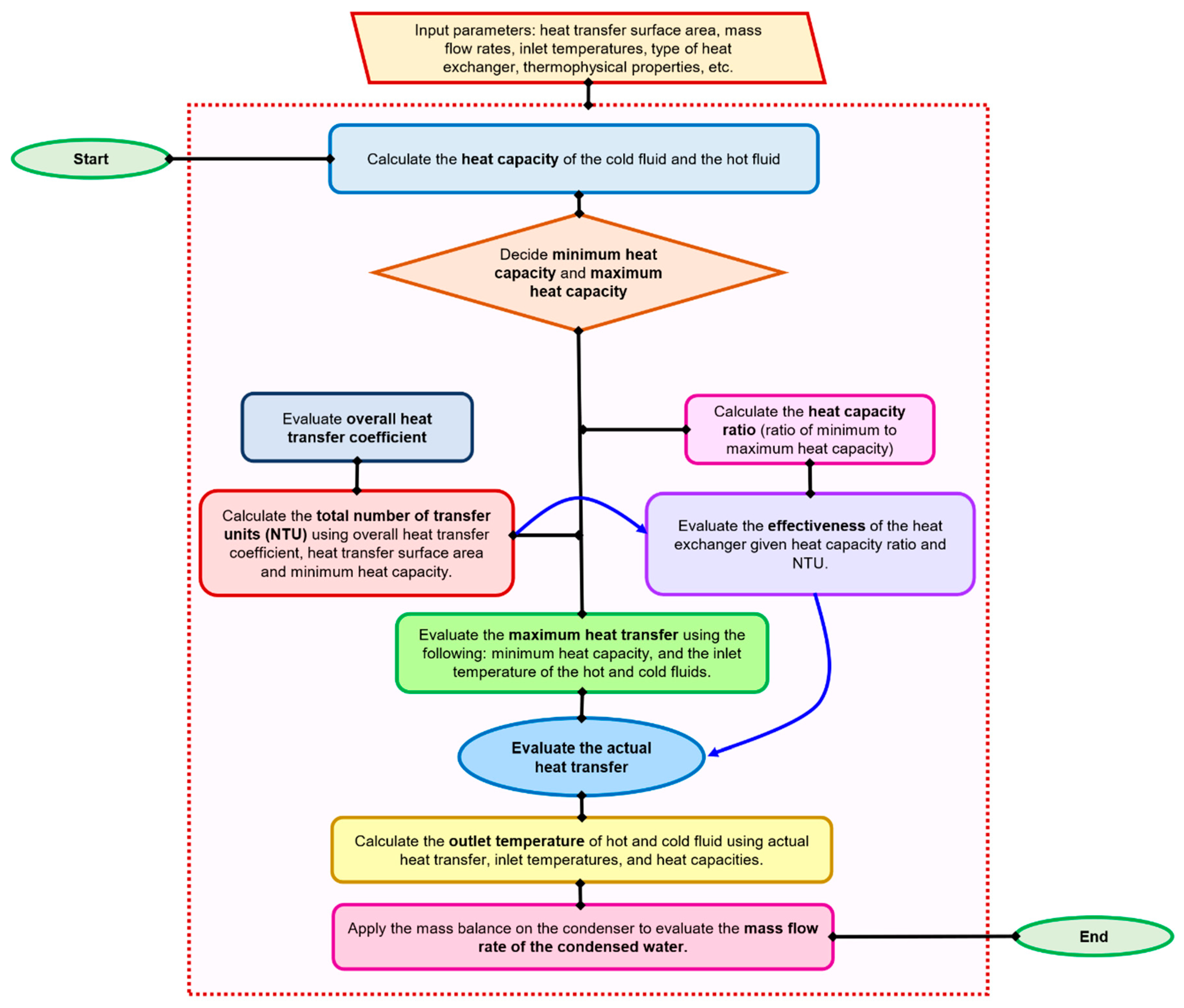
The efficacy of the condenser, modelled as a counter-flow concentric heat exchanger, is computed using NTU (Number of Transfer Units) method [77,78,79] which is used to calculate the rate of heat transfer in heat exchangers when there is an insufficient data to evaluate the Log-Mean-Temperature-Difference [77,78,79].
Therefore, in NTU method, the effectiveness of the heat exchanger is calculated which can be converted into the actual heat transfer of the heat exchanger. It also involves the calculation of minimum heat capacity (Cmin) and maximum heat capacity (Cmax) which can be either heat capacity of the cold fluid or the hot fluid depending on whichever can be minimum or maximum. The evaluation of U is carried out using the thermal resistance diagram by computing the convective heat transfer coefficient of the humidifier and feed water. Once the actual heat transfer is calculated, it can be used to evaluate the outlet temperatures of both steam and finally, the mass balance can give the quantity of the condensed fresh water. This methodological framework is presented in a stepwise format as in Figure 4.
3.5. Auxilary Equations
The auxiliary equations aids in the extraction of the temperature-dependent thermophysical properties of different fluids. These are mostly empirical equations and their usage in this work was practised with precaution in which the limit of each model is verified with the database of Engineering Equation Solver [80] before the final implementation.
The thermal conductivity of the dry air is given by [81]:
The thermal conductivity of the water vapour is given by [81]:
The thermal conductivity of the humid air is given by [81]:
The latent heat of vaporization is given by [82]:
The specific heat of dry air is given by [81]:
The specific heat of water vapour is given by [81]:
Finally, the specific heat of humid air is calculated using [81]:
The dynamic viscosity of dry air in terms of the temperature is given by [81]:
The dynamic viscosity of water vapour is given by [81]:
Finally, for the humid air, the dynamic viscosity is [81]:
4. Benchmarking of Simulation Results
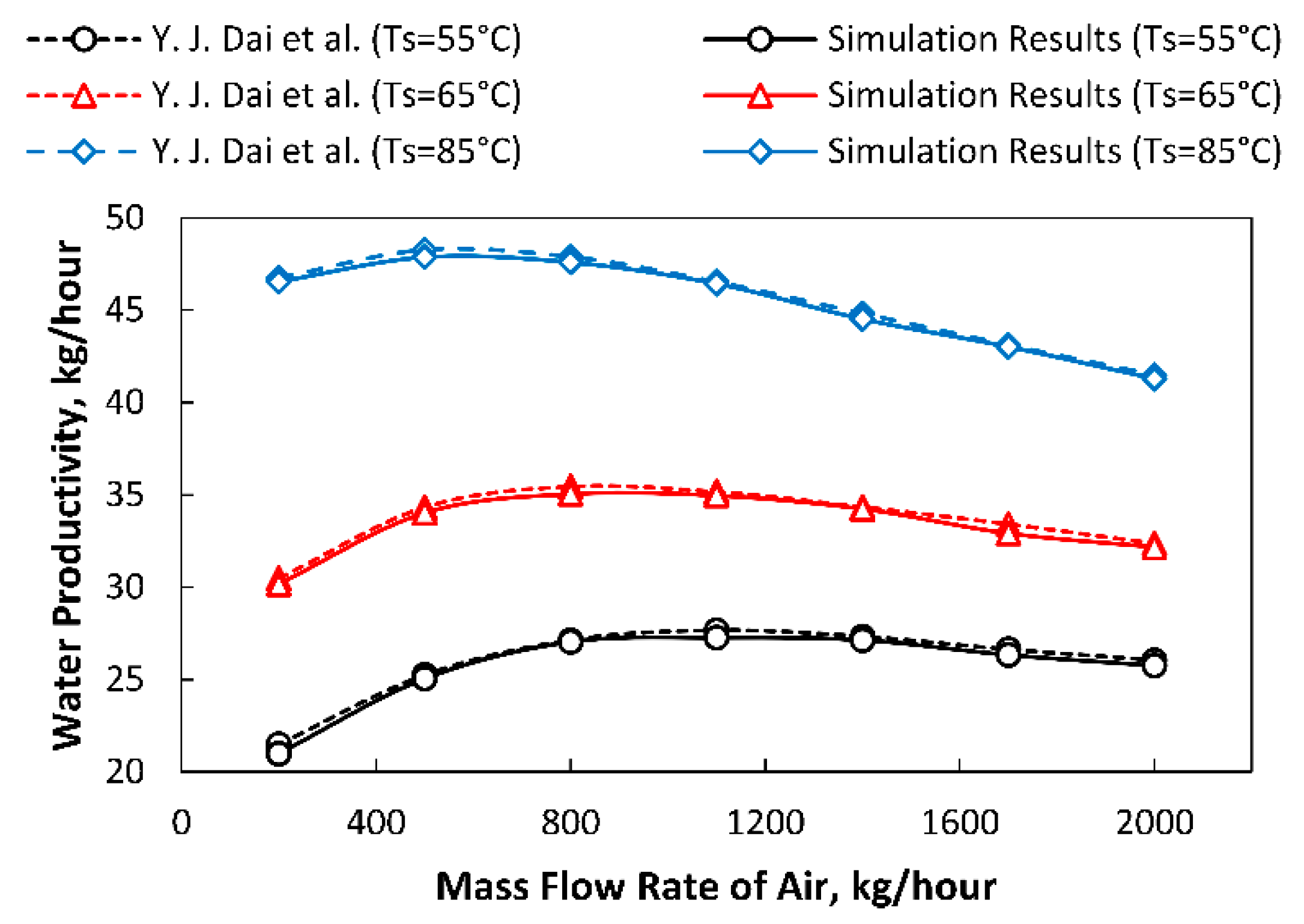
The benchmarking of the current simulation results is accomplished by comparison with the experimental and the simulation results of Dai et al. [75] without considering the waste heat recovery of the feedwater from the condensing coil. A solar desalination study having humidification and dehumidification processes, both mathematically and experimentally, was presented. All of the conditions considered by Dai et al. [75] are codified in MATLAB simulation and the desired results are obtained. The initial conditions for this benchmarking are: inlet temperature of the air is 35 °C, inlet relative humidity is 40%, MFR of saline water is 1500 kg/h, the NTUs of condensing coil are 4, the MFR of cooling coil is 2500 kg/h, and the incident solar radiation is 700 W/m2. The humidifier is 0.6m long and has a cross-sectional area of 0.56m2. Considering these input parameters in the developed code, the compliance between the current simulation results and the simulation results of Dai et al. [75] are shown in Figure 5 in which the variation in water productivity is shown with changing MFR of working air along with different water film temperature. A maximum discrepancy of 2.33% is observed between both simulation results. The discrepancy is caused by the advanced modelling of solar collector adapted by the authors as compared to the relatively simplified mathematical model of [75]. It is to be stressed here that the feed water recirculation (waste heat recovery) [83] is not included for this comparison to fully replicate the conditions of [75].
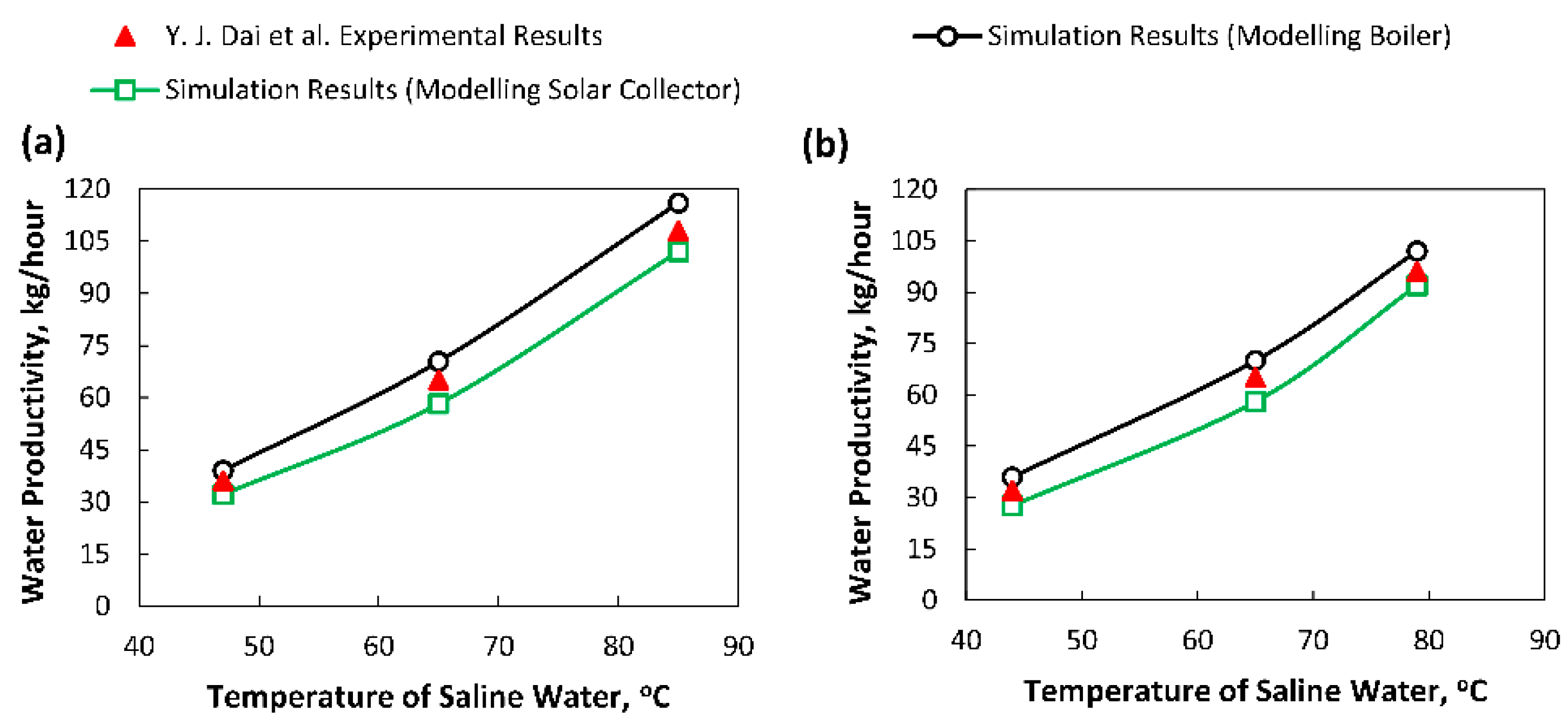
The results of the simulation study are also benchmarked by comparison with the experimental results of Dai et al. [75]. A comparison is carried out for two cases. For the case, I, the MFR of air is 615.6 kg/h, and the ambient relative humidity is 54%. For case II: the MFR of air is 661.8 kg/h, and relative humidity is 49%. For both cases: the ambient air temperature is ~22 °C, the feedwater temperature is ~19 °C, the MFR of saline water is 2310 kg/h and the MFR of feed water in condensing coil is 3780 kg/h. Here it is stressed that the authors of [75] replaced the solar collector by a boiler to obtain quick lab results during experimentation. The authors of the current work carried out analysis by considering the solar collector. Subsequently, an analysis is also carried out by solving the boiler as a heat input. The analysis considering boiler and solar collector along with experimental data of [75] for each of the case I and case II is shown in Figure 6a,b. It can be observed here that the water productivity level for the solar collector is lower than the experimental data points because the heat loss coefficient (UL) for the solar collector case is contributing significantly which was absent in the experimental setup of [75]. However, the water productivity level for the case in which the authors simulated the boiler is higher than the experimental data points because of the assumptions considered in Section 3.3. Based on this discussion, the maximum discrepancy observed for this benchmarking is ~8% for both cases as reported in Figure 6a,b which is a plot between the temperature of saline water and water productivity level.
5. Results and Discussion
This work aims to recover the heat from the condensing coil. Therefore, in this section, different parameters are varied to observe their effect on freshwater productivity with and without the waste heat recovery.
5.1. Mass Flow Rate (MFR) of Inlet Air Effect on Freshwater Production
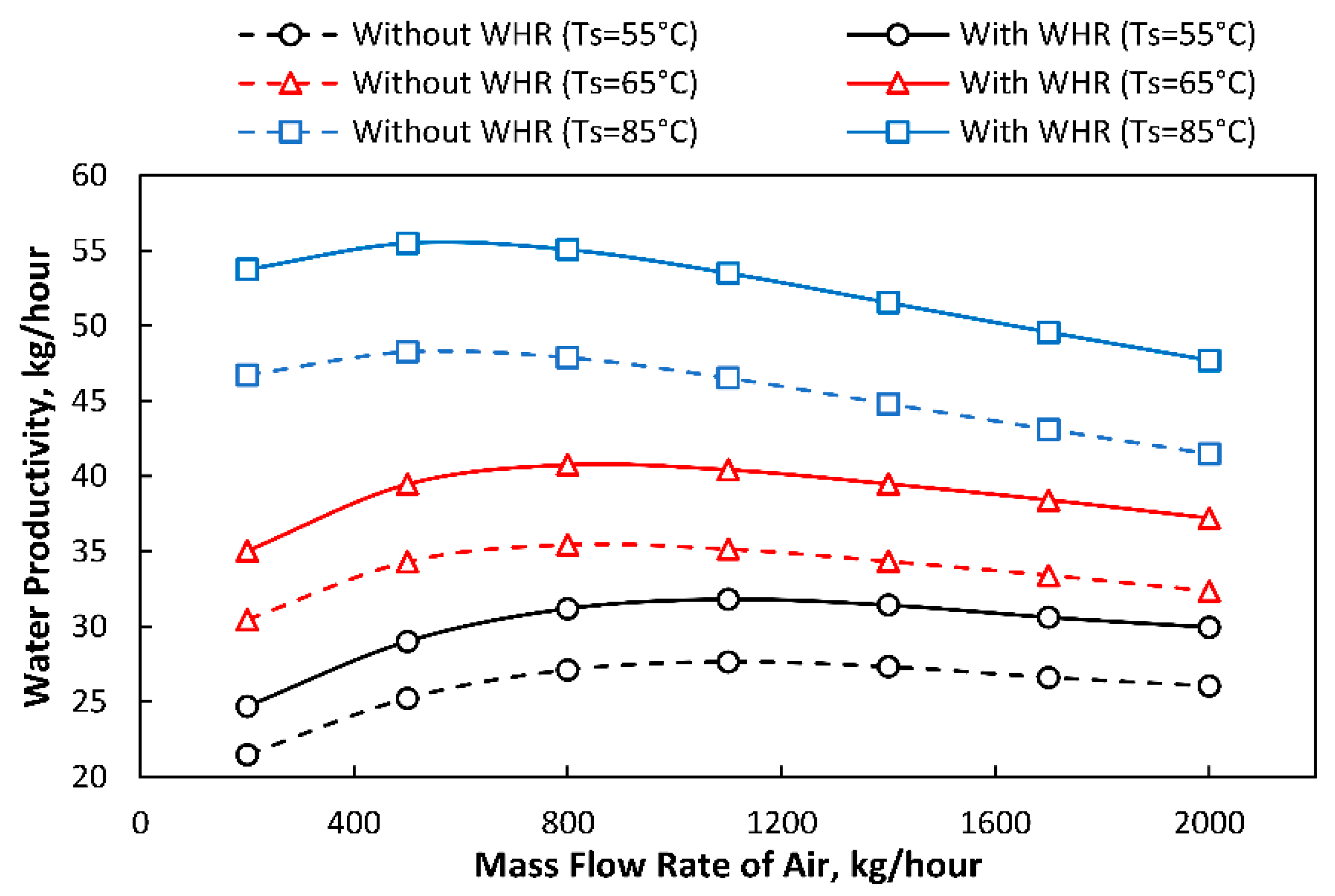
The intake of MFR of air is an important parameter in a desalination unit because it determines the blowing power. Therefore, simulations are carried out to observe the influence of MFR of air on water productivity with and without waste heat recovery from the condensing coil and it is presented in Figure 7.
It is observed that the water productivity is increased with the increase in MFR of air because the tendency of moisture transfer increases; therefore, water productivity attains a maximum value at 500–800 kg/h of MFR of air. However, water productivity decreases significantly after 1100 kg/h of MFR of air. It is because very high values of MFR of air do not give sufficient time to an air in the humidification section to cause effective evaporation; therefore, as a result, the water productivity decreases. Dai et al. [75] recommended a range of 500–800 kg/h of the MFR of air for the HDH desalination unit, which can be also observed here. It is also observed that elevating the temperature of the saline water also increases the productivity of freshwater. However, it is deduced from Figure 5 that recovering the heat from the condensing coil by reusing the feedwater in the brackish water storage significantly increases the freshwater productivity. It is reported that ~14% of freshwater productivity is increased for an MFR of 800 kg/h by waste heat recovered from the condensing coil at a saline water temperature of 85 °C.
5.2. Mass Flow Rate (MFR) of Saline Water Effect on Freshwater Production
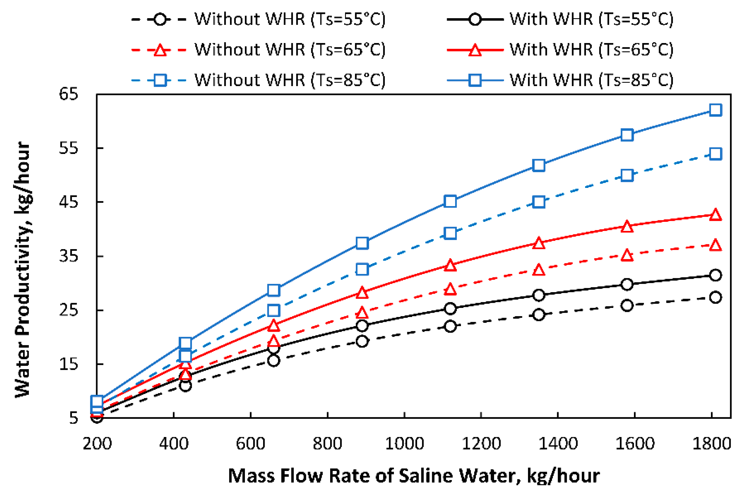
Several simulations are carried out to observe the effect of MFR of saline water on freshwater productivity from the dehumidifier/condenser. It can be observed from Figure 8 that an increase in the MFR of the saline water increases the water production rate. It is because a high MFR of saline water contributes to a high Reynolds number, thus increasing the heat transfer coefficient between the water and air mixture in the humidification section, which yields higher values of water productivity. It can also observe that increasing the saline water temperature increases the freshwater productivity. Since the mass transfer coefficient is a strong function of temperature, therefore, it contributes towards a more effective mass transfer of water vapours to air. Furthermore, it is observed that the freshwater productivity also increases by waste heat recovered. Here, an increase of ~15% in water productivity is reported by waste heat recovery from the condensing coil for a saline water MFR of 1800 kg/h at a water film temperature of 85 °C.
5.3. Mass Flow Rate (MFR) of Feedwater Effect on Freshwater Productivity
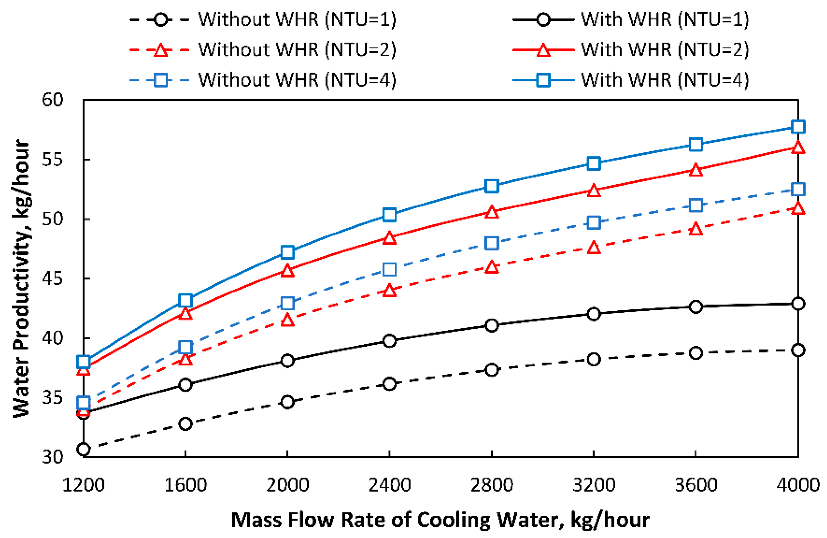
The MFR of cooling water in the condensing coil is changed from 1200 kg/h to 4000 kg/h and its influence on freshwater productivity is studied. The simulation was carried out on three different values (1, 2, and 4) of NTU of the condensing coil. The influence of waste heat recovery is also presented here.
It can be witnessed in Figure 9 that the hourly freshwater production is directly proportional to the MFR of the cooling water because its increment decreases the surface temperature of the condenser which can increase condensation rate. Furthermore, water productivity is increasing with the increase in the NTU of the condensing coil. A higher value of NTU corresponds to a higher value of the overall heat transfer coefficient in the condensing coil. Therefore, it increases the actual heat transfer; and as a result, the hourly freshwater production is increased. Furthermore, here it is shown that the hourly production rate of freshwater is increased to 10% by waste heat recovered from the condensing coil at an MFR of cooling water of 4000 kg/h.
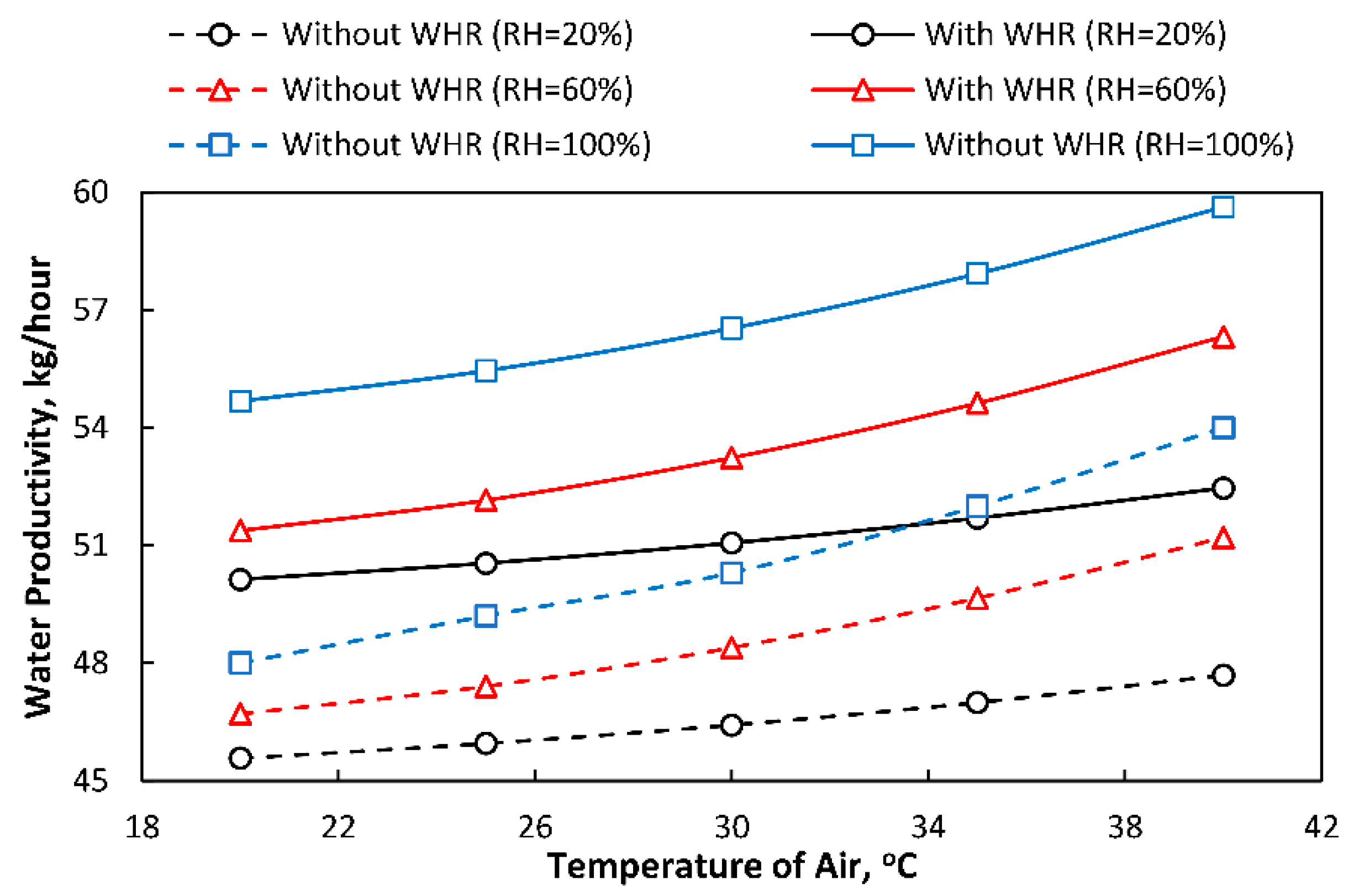
5.4. Effect of the Temperature of the Air on Freshwater Productivity
In this section, a simulation is carried out to study the effect of the ambient air temperature on the freshwater productivity. These results are important as they will govern the applicability of the desalination unit. Since this desalination unit is working on humidification principle; therefore, the ambient air conditions are crucial. The behaviour is reported in Figure 10.
It is observed that the hourly freshwater production rate is directly proportional to the ambient temperature of air because the increment in it enhances the heat and mass transfer characteristics in the humidification chamber. Furthermore, it is reported that the freshwater production rate is also directly proportional to the relative humidity at the exit of the humidification chamber (state 8). This is because higher relative humidity at the exit of the humidification section indicates a small difference between the dry bulb and the dew point temperature of the air which is an assertive parameter towards condensation. It is also reported here that the hourly freshwater production rate is increased to ~11% by waste heat recovered from the condensing coil at an ambient air temperature of 45 °C at full saturation conditions at the exit of the humidification chamber.
5.5. Yearly Analysis of Freshwater Productivity with and without Waste Heat Recovery
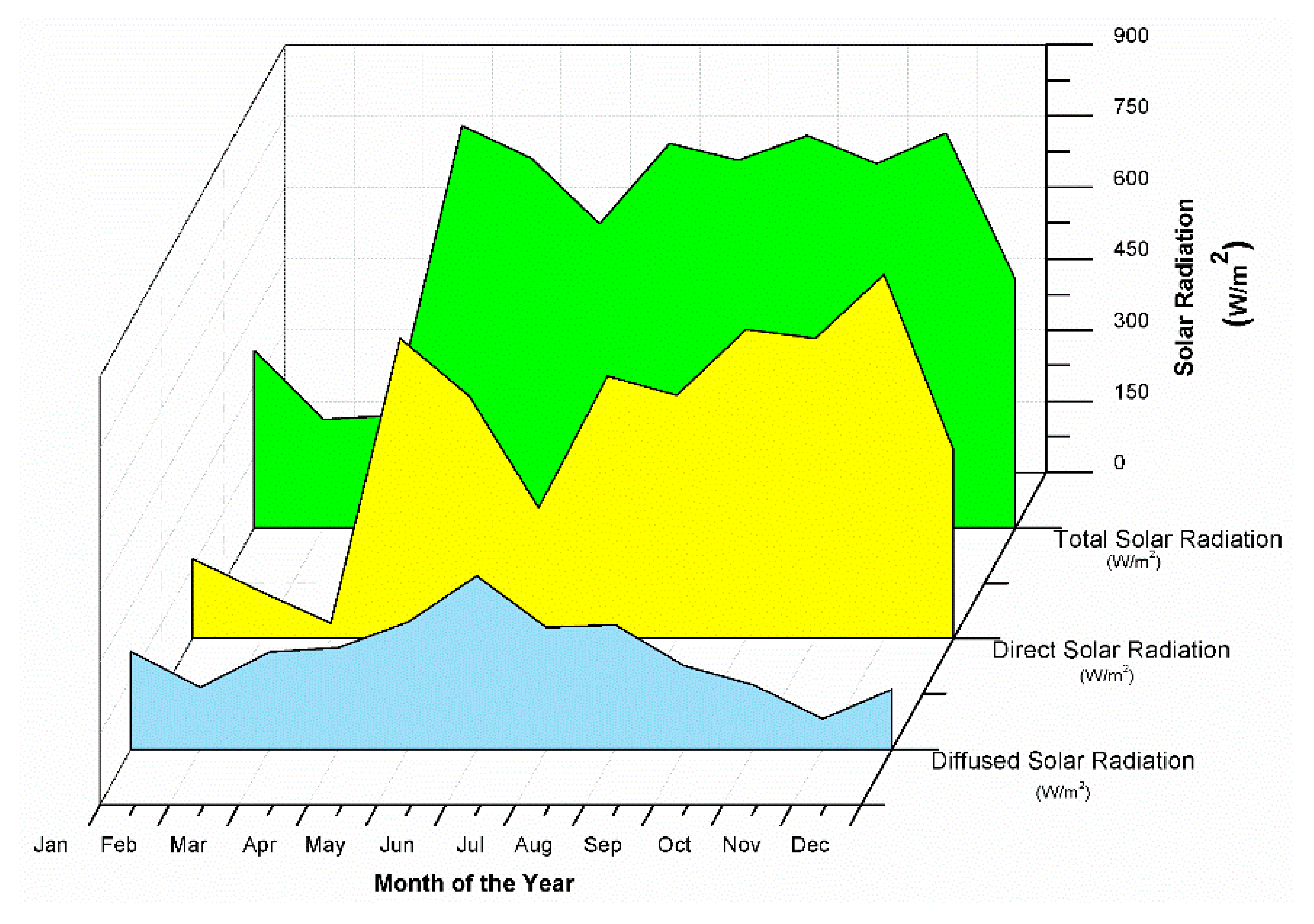
In this section, an analysis is carried out to observe the freshwater productivity rate yearly. As the plant uses solar radiation for heating, therefore its actual output will be important for different days of the year. For this purpose, the selected day of each month is used for the calculation of flat-plate solar collectors. Table 2 shows the representative day of each month [84] that is selected to carry out an analysis. Selected data such as ambient temperature, ambient relative humidity, and velocity for analysis purposes are reported in Table 2. The solar radiation data, including total incident, beam, and diffuse radiation for Taxila, is presented in Figure 11.
Figure 12 shows the yearly freshwater productivity from the solar-assisted desalination HDH plant with and without waste heat recovery from the condensing coil. The lower freshwater production rate is observed for April and May. Although a significant amount of solar radiation is experienced in these months (Figure 11) but the region of Taxila (33.745833, 72.7875) experiences high wind velocities in these months. Therefore, it increases the overall heat transfer coefficient of the solar collector, which yields lower water production rates. The highest freshwater production rate is observed for July where the incident radiation is maximum, and the wind velocities are low. The water production rate in November, December, January, and February are relatively high. Even though low ambient temperatures are observed in these months, but relatively higher values of incident radiation and lower wind velocities are observed; therefore, the water production rate is also relatively high. The water production rate in August is low because Taxila experiences very high humidity this month; therefore, it decreases the potential of the humidification process in the desalination unit. One important phenomenon can be observed from Figure 12 that the water production is high for each month of the year if the waste heat from the condensing coil is recovered. It is reported here that the freshwater productivity is increased by ~16% for June by recovering the waste heat from the condensing coil.
6. Economic Assessment
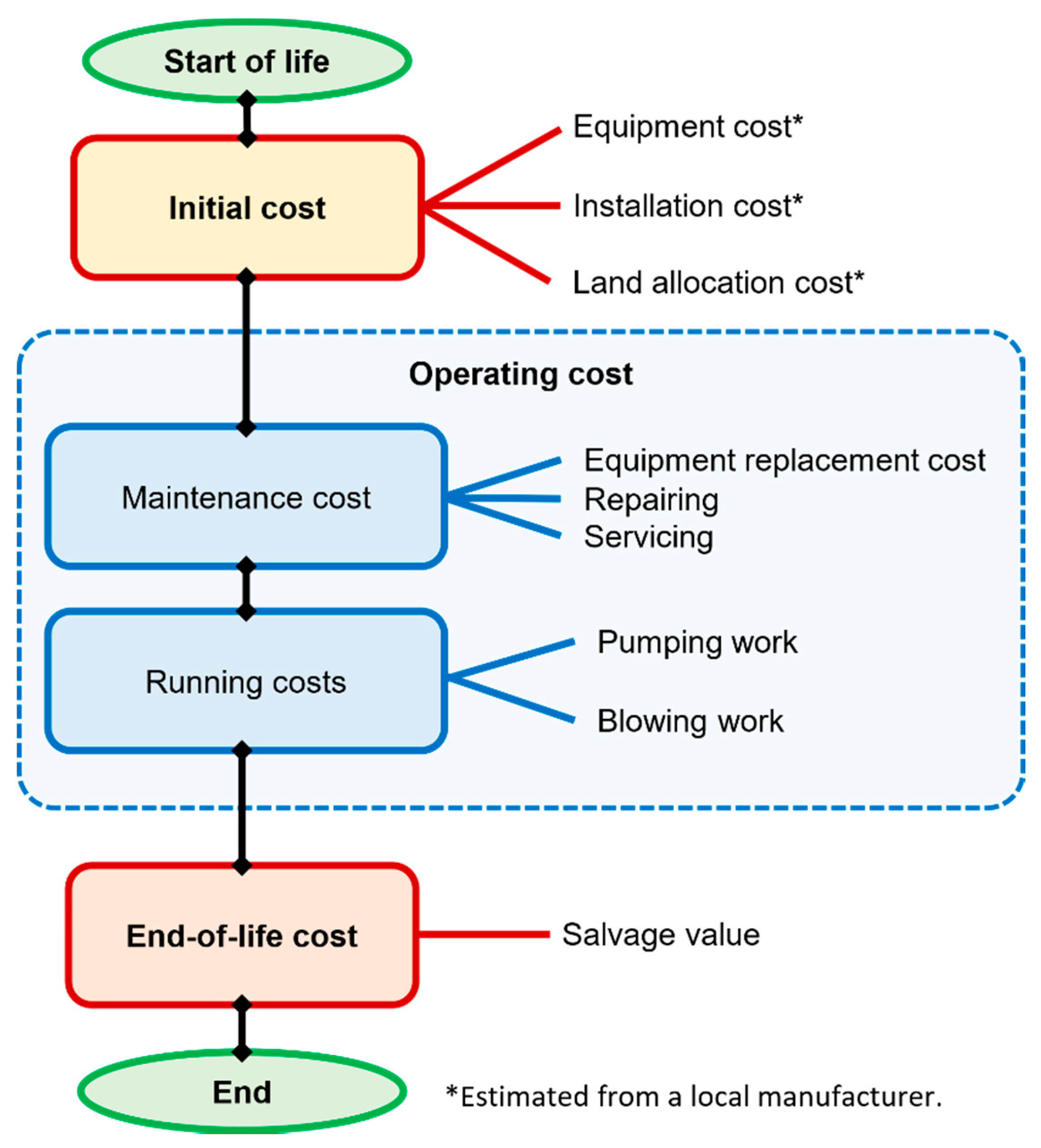
Kaya et al. [6] carried out a levelized cost analysis for solar-energy-powered seawater desalination in the Emirate of Abu Dubai and considered multi-stage flash and multi-effect distillation coupled with thermal power plants while mentioning that these thermal desalination methods are responsible for more than 90% of the desalination capacity in the Emirate. The findings of the article [6] suggest that the analysis considering the levelized cost of water for a combination of solar PV and a reverse osmosis system is technologically well-positioned in terms of cheap and clean desalination systems. The authors of reference [6] considered total capital cost, annual energy consumption with a required solar energy system to balance a zero in the grid along with the chemical costs and overhead cost yielding a final levelized cost of water. A similar approach is adopted here in which the economic assessment involves an estimation of the levelized cost of water production using the total cost of ownership method, which involves capital cost, maintenance cost, energy cost, and salvage value. This process is depicted in Figure 13.
The following variables are considered for the economical assessment. Solar collector: The thickness of the glass cover is 3 mm, the emittance of the glass is 0.88, the refractive index of glass is 1.526, the refractive index of air is 1, the absorptance factor of the absorber plate is 0.94, the extinction coefficient of the glass is 32 m−1, the area of absorber plate is 1.5 m2, the number of tubes are 20, having an effective length of 20 m, while the spacing between the tubes is 50 mm, with each tube thickness of 1 mm, having an outdoor diameter of 10 mm, and the mass flow rate of water at the inlet of the solar collector is 0.005 kg/s. Humidifier: The length of the section is 1 m with a width of 600 mm and a height of 20 mm, the total mass flow rate is 0.05 kg/s. Dehumidifier: The total heat transfer surface area is 1.5 m2, the temperature of water at the inlet of the condenser is 20 °C, the feed water mass flow rate is 0.01 kg/s, the inner diameter of tubes is 5 mm, the total number of tubes are 20 having an effective length of 10 m, and the shell diameter is 200 mm. Turbomachinery: The isentropic efficiency of pumps and blowers is 0.85, the mechanical efficiency of pumps is 0.96, and the mechanical efficiency of blowers is 0.90. Based on these data, the total initial cost of the system including the land and the equipment cost is estimated from the local manufacturers and comes out to be 18,000 PKR.
For an interest rate of 4%, and a life expectancy of 10 years, the capital recovery factor is given by:
The first annual cost can be calculated using the initial cost, and the capital recovery factor, given by:
The maintenance cost is considered 5% of the first annual cost. The total running cost of the equipment involves the annual energy consumption given by:
The energy consumption of the pump is calculated by considering the enthalpy difference times mass flow rate corrected by its mechanical efficiency, and it is given by [85]:
where is the mass flow rate (kg/s) of water in the section, is the enthalpy (kJ/kg) and is the mechanical efficiency of pump which is considered 0.96 [86]. The blower is calculated by considering the pressure drop and it is given by [87]:
The details of the parameters used in Equation (39) is given as follows:
- The pressure drop is calculated by considering the hydraulic calculation formulas, and it is given by:where is the friction factor, is the non-dimensional Reynolds number, is the effective length of the channel, is the hydraulic diameter, is the density of air, and is the averaged velocity of the channel calculated using the ratio of volume flow rate per unit cross-sectional area. These parameters are calculated for humidifier and dehumidifier section differently and finally, the aggregation of both pressure differences gives the total pressure difference. The friction factor is given by the empirical formula:The aspect ratio is a comparison between the shorter and the longer side of the cross-section of the air channel given by:
- is the internal efficiency of the fan which is considered 0.75 [88].
- is the mechanical efficiency of the fan which is considered 0.9 [89].
- is the motor capacity coefficient which is 1.1 [90].
For an industrial rate of the cost of electricity at 12 PKR/kWh, the annual running cost is 8,176,000 PKR. The salvage value is calculated using the sinking fund factor, given by:
Finally, the total annual cost is calculated using the balance of life cycle costs, given by:
With this methodology, the production cost of desalinated water is 17.16 PKR/litre (0.15 USD/litre) without waste heat recovery and it is 14.85 PKR/litre (0.13 USD/litre) with waste heat recovery. Therefore, the production cost of the water is decreased by ~13% by recovering the waste heat from the condensing coil.
7. Conclusions
In this research paper, a simulation is carried out for the humidification-dehumidification (HDH) type of desalination system in which the emphasis is given to the performance of the plant by recovering the heat from the condensing coil by reusing the feed water in the brackish water storage tank. The feedwater is recirculated because it has relatively high enthalpy as it absorbs energy in the dehumidification process of air. The mathematical model of the system is simulated, and the results are validated by comparing them with the previously published experimental and numerical results without waste heat recovery. Afterwards, an extensive parametric study is conducted in which MFR of inlet air, saline water, feedwater, and the temperature of ambient air are varied. It is observed that; for all cases, the freshwater productivity rate is increased to a maximum of 15% by recovering the heat from the condensing coil. The yearly analysis of freshwater was carried out and it is observed that the freshwater productivity is increased to a maximum of ~16% in June. Furthermore, economic analysis has demonstrated that the cost of desalinated water is decreased by ~13% by recovering the heat from the condensing coil and it is 0.13 USD/litre. It is concluded that the proposed system enhances the performance of an existing HDH desalination system.
However, this work is a theoretical analysis of the waste heat recovery from the condenser of the desalination system, which is finally a physical connection, in the form of piping and tubing, from the dehumidifier to the storage tank. This piping can contribute to some practical limitation in the cycle and other studies considering the ‘design for manufacturing and assembly’ are suggested before the mass-scale production.
Author Contributions
Conceptualization, R.T., and N.A.S.; methodology, R.T., and N.A.S.; software, R.T.; validation, R.T. and N.A.S.; formal analysis, R.T., J.T.J., N.A.S., and S.K.; investigation, R.T., J.T.J., N.A.S., and S.K.; resources, J.T.J.; data curation, R.T.; writing—original draft preparation, R.T.; writing—review and editing, R.T., J.T.J., N.A.S., and S.K.; visualization, R.T.; supervision, N.A.S.; project administration, S.K.; funding acquisition, J.T.T. All authors have read and agreed to the published version of the manuscript.
Funding
Tecnológico Nacional de México / Instituto Tecnológico Superior de Huauchinango, Av. Tecnológico No. 80, Col. 5 de Octubre, Huauchinango 73173, Puebla, México.
Acknowledgments
The first author, Rasikh Tariq, is thankful for the financial support granted by CONACYT (‘Consejo Nacional de Ciencia y Tecnología’ as in Spanish); with the following details CVU no. 949314, scholarship no. 730315, to pursue a postgraduate degree in Universidad Autónoma de Yucatán, Mexico. The authors are thankful for the financial support of Instituto Tecnológico Superior de Huauchinango. The second author, Jacinto Torres Jimenez, is thankful to CONACYT for the SNI (‘Sistema Nacional de Investigadores’ as in Spanish) system.
Conflicts of Interest
The authors declare no conflict of interest. The funders had no role in the design of the study; in the collection, analyses, or interpretation of data; in the writing of the manuscript, or in the decision to publish the results.
Nomenclature
| Letters | |
| Ac | Collector Area, m2 |
| cp | Specific Heat of Air, J/kg. K |
| d | Thickness of Film, m |
| Diameter of collector tubes, m | |
| Effectiveness of dehumidifier | |
| Fin efficiency | |
| Collector heat removal factor | |
| Collector efficiency factor | |
| g | Gravitational acceleration, m/s2 |
| h | Convective Heat Transfer Coefficient, W/m2. K |
| hnumber | Enthalpy, J/kg |
| H | Enthalpy, kJ/kg |
| I | Radiation, W/m2 |
| m | Mass flow rate, kg/s |
| M | Molecular Weight of Water |
| HDH | Humidification-Dehumidification |
| P | Pressure, Pa |
| Qu | Useful heat gain, W |
| R | General Gas Constant, J/mol. K |
| Rayleigh number | |
| S | Absorbed Solar Radiation, W/m2 |
| T | Temperature, K |
| U | Heat Transfer Coefficient, W/m2. K |
| u,v | Velocity, m/s |
| Spacing between the collector tubes, m | |
| Wj | Water Evaporation Rate, kg/m2 |
| WER | Waste Heat Recovery |
| y, z | Coordinate system, m |
| Subscript | |
| a | Air |
| s | Saturated |
| v | Vapor |
| w | Water |
| d | Diffused Radiation |
| Symbols | |
| α | Thermal Diffusivity, m2/s |
| Thermal absorptivity of absorber plate of the solar collector | |
| β | Title Angle, degree |
| Transmittance-absorptance product | |
| ε | Knudson Coefficient of Evaporation |
| Emissivity of absorber plate | |
| Latitude angle | |
| Reflectance of a single cover | |
| Dynamic viscosity of water, kg/m.s | |
| Mass flow rate of saline water per unit width of the wall, kg/s/m | |
| Earth’s declination angle | |
| δs | Falling Film Water Thickness, m |
| λ | Latent Heat of Water, kJ/kg |
| ρ | Density, kg/m3 |
| θe | Angle of Incidence, Degree |
| ω | Absolute Humidity of Air, kg/kg |
| Hour Angle | |
| Superscript | |
| s | Related to Solar Collector |
| h | Related to Humidifier |
References
- Sharshir, S.W.; Peng, G.; Yang, N.; El-Samadony, M.O.A.; Kabeel, A.E. A continuous desalination system using humidification–Dehumidification and a solar still with an evacuated solar water heater. Appl. Therm. Eng. 2016, 104, 734–742. [Google Scholar] [CrossRef]
- Zhang, L.Z.; Li, G.P. Energy and economic analysis of a hollow fiber membrane-based desalination system driven by solar energy. Desalination 2017, 404, 200–214. [Google Scholar] [CrossRef]
- Predescu, A.; Truică, C.-O.; Apostol, E.-S.; Mocanu, M.; Lupu, C. An Advanced Learning-Based Multiple Model Control Supervisor for Pumping Stations in a Smart Water Distribution System. Mathematics 2020, 8, 887. [Google Scholar] [CrossRef]
- Manju, S.; Sagar, N. Renewable energy integrated desalination: A sustainable solution to overcome future fresh-water scarcity in India. Renew. Sustain. Energy Rev. 2017, 73, 594–609. [Google Scholar] [CrossRef]
- Chandrashekara, C.; Yadav, A. Water desalination system using solar heat: A review. Renew. Sustain. Energy Rev. 2017, 67, 1308–1330. [Google Scholar]
- Kaya, A.; Tok, M.; Koc, M. A Levelized Cost Analysis for Solar-Energy-Powered Sea Water Desalination in The Emirate of Abu Dhabi. Sustainability 2019, 11, 1691. [Google Scholar] [CrossRef] [Green Version]
- Abdelkareem, M.A.; Assad, M.E.H.; Sayed, E.T.; Soudan, B. Recent progress in the use of renewable energy sources to power water desalination plants. Desalination 2018, 435, 97–113. [Google Scholar] [CrossRef]
- Rabbani, M.; Ratlamwala, T.A.H.; Dincer, I. Transient energy and exergy analyses of a solar based integrated system. J. Sol. Energy Eng. Trans. ASME 2014, 137, 011010. [Google Scholar] [CrossRef]
- Reif, J.H.; Alhalabi, W. Solar-thermal powered desalination: Its significant challenges and potential. Renew. Sustain. Energy Rev. 2015, 48, 152–165. [Google Scholar] [CrossRef]
- Giwa, A.; Akther, N.; Al Housani, A.; Haris, S.; Hasan, S.W. Recent advances in humidification dehumidification (HDH) desalination processes: Improved designs and productivity. Renew. Sustain. Energy Rev. 2016, 57, 929–944. [Google Scholar] [CrossRef]
- Kabeel, A.E.; Hamed, M.H.; Omara, Z.M.; Sharshir, S.W. Experimental study of a humidification-dehumidification solar technique by natural and forced air circulation. Energy 2014, 68, 218–228. [Google Scholar] [CrossRef]
- Hamed, M.H.; Kabeel, A.E.; Omara, Z.M.; Sharshir, S.W. Mathematical and experimental investigation of a solar humidification-dehumidification desalination unit. Desalination 2015, 358, 9–17. [Google Scholar] [CrossRef]
- Bakthavatchalam, B.; Rajasekar, K.; Habib, K.; Saidur, R.; Basrawi, F. Numerical analysis of humidification dehumidification desalination system. Evergreen 2019, 6, 9–17. [Google Scholar] [CrossRef]
- Zhani, K.; Ben Bacha, H. Experimental investigation of a new solar desalination prototype using the humidification dehumidification principle. Renew. Energy 2010, 35, 2610–2617. [Google Scholar] [CrossRef]
- Elminshawy, N.A.S.; Siddiqui, F.R.; Sultan, G.I. Development of a desalination system driven by solar energy and low grade waste heat. Energy Convers. Manag. 2015, 103, 28–35. [Google Scholar] [CrossRef]
- Narayan, G.P.; Sharqawy, M.H.; Summers, E.K.; Lienhard, J.H.; Zubair, S.M.; Antar, M.A. The potential of solar-driven humidification-dehumidification desalination for small-scale decentralized water production. Renew. Sustain. Energy Rev. 2010, 14, 1187–1201. [Google Scholar] [CrossRef]
- Narayan, G.P.; Sharqawy, M.H.; Lienhard, V.J.H.; Zubair, S.M. Thermodynamic analysis of humidification dehumidification desalination cycles. Desalin. Water Treat. 2010, 16, 339–353. [Google Scholar] [CrossRef] [Green Version]
- Narayan, G.P.; John, M.G.S.; Zubair, S.M.; Lienhard, J.H. Thermal design of the humidification dehumidification desalination system: An experimental investigation. Int. J. Heat Mass Transf. 2013, 58, 740–748. [Google Scholar] [CrossRef]
- Narayan, G.P.; Chehayeb, K.M.; McGovern, R.K.; Thiel, G.P.; Zubair, S.M.; Lienhard, V.J.H. Thermodynamic balancing of the humidification dehumidification desalination system by mass extraction and injection. Int. J. Heat Mass Transf. 2013, 57, 756–770. [Google Scholar] [CrossRef] [Green Version]
- Thiel, G.P.; Lienhard, J.H. Entropy generation in condensation in the presence of high concentrations of noncondensable gases. Int. J. Heat Mass Transf. 2012, 55, 5133–5147. [Google Scholar] [CrossRef] [Green Version]
- Summers, E.K.; Arafat, H.A.; Lienhard, V.J.H. Energy efficiency comparison of single-stage membrane distillation (MD) desalination cycles in different configurations. Desalination 2012, 290, 54–66. [Google Scholar] [CrossRef]
- McGovern, R.K.; Thiel, G.P.; Narayan, G.P.; Zubair, S.M.; Lienhard, V.J.H. Performance limits of zero and single extraction humidification-dehumidification desalination systems. Appl. Energy 2013, 102, 1081–1090. [Google Scholar] [CrossRef]
- Mistry, K.H.; McGovern, R.K.; Thiel, G.P.; Summers, E.K.; Zubair, S.M.; Lienhard, J.H. Entropy Generation Analysis of Desalination Technologies. Entropy 2011, 13, 1829–1864. [Google Scholar] [CrossRef] [Green Version]
- Mistry, K.H.; Lienhard, J.H.; Zubair, S.M. Effect of entropy generation on the performance of humidification- dehumidification desalination cycles. Int. J. Therm. Sci. 2010, 49, 1837–1847. [Google Scholar] [CrossRef] [Green Version]
- Sharqawy, M.H.; Lienhard, V.J.H.; Zubair, S.M. On exergy calculations of seawater with applications in desalination systems. Int. J. Therm. Sci. 2011, 50, 187–196. [Google Scholar] [CrossRef]
- Sharqawy, M.H.; Antar, M.A.; Zubair, S.M.; Elbashir, A.M. Optimum thermal design of humidification dehumidification desalination systems. Desalination 2014, 349, 10–21. [Google Scholar] [CrossRef]
- Khalifa, A.; Ahmad, H.; Antar, M.; Laoui, T.; Khayet, M. Experimental and theoretical investigations on water desalination using direct contact membrane distillation. Desalination 2017, 404, 22–34. [Google Scholar] [CrossRef]
- Summers, E.K.; Antar, M.A.; Lienhard, J.H. Design and optimization of an air heating solar collector with integrated phase change material energy storage for use in humidification-dehumidification desalination. Sol. Energy 2012, 86, 3417–3429. [Google Scholar] [CrossRef]
- Al-Sulaiman, F.A.; Zubair, M.I.; Atif, M.; Gandhidasan, P.; Al-Dini, S.A.; Antar, M.A. Humidification dehumidification desalination system using parabolic trough solar air collector. Appl. Therm. Eng. 2015, 75, 809–816. [Google Scholar] [CrossRef]
- Lawal, D.; Antar, M.; Khalifa, A.; Zubair, S.; Al-Sulaiman, F. Humidification-dehumidification desalination system operated by a heat pump. Energy Convers. Manag. 2018, 161, 128–140. [Google Scholar] [CrossRef]
- Gabrielli, P.; Mazzotti, M. Solar-Driven Humidification-Dehumidification Process for Water Desalination Analyzed and Optimized via Equilibrium Theory. Ind. Eng. Chem. Res. 2019, 58, 15244–15261. [Google Scholar] [CrossRef] [Green Version]
- Gabra, B.; Rady, M.; Ghany, A.M.A.; Shamseldin, M.A. Modelling and control of solar-driven humidification–dehumidification desalination plant. J. Electr. Syst. Inf. Technol. 2019, 6, 7. [Google Scholar] [CrossRef] [Green Version]
- Zubair, M.I.; Al-Sulaiman, F.A.; Antar, M.A.; Al-Dini, S.A.; Ibrahim, N.I. Performance and cost assessment of solar driven humidification dehumidification desalination system. Energy Convers. Manag. 2017, 132, 28–39. [Google Scholar] [CrossRef]
- Jamil, M.A.; Shahzad, M.W.; Zubair, S.M. A comprehensive framework for thermoeconomic analysis of desalination systems. Energy Convers. Manag. 2020, 222, 113188. [Google Scholar] [CrossRef] [PubMed]
- Xu, H.; Zhao, Y.; Dai, Y.J. Experimental study on a solar assisted heat pump desalination unit with internal heat recovery based on humidification-dehumidification process. Desalination 2019, 452, 247–257. [Google Scholar] [CrossRef]
- Tariq, R.; Sheikh, N.A.; Xamán, J.; Bassam, A. An innovative air saturator for humidification-dehumidification desalination application. Appl. Energy 2018, 228, 789–807. [Google Scholar] [CrossRef]
- Ahmed, H.A.; Ismail, I.M.; Saleh, W.F.; Ahmed, M. Experimental investigation of humidification-dehumidification desalination system with corrugated packing in the humidifier. Desalination 2017, 410, 19–29. [Google Scholar] [CrossRef]
- Yildirim, C.; Solmuş, I. A parametric study on a humidification-dehumidification (HDH) desalination unit powered by solar air and water heaters. Energy Convers. Manag. 2014, 86, 568–575. [Google Scholar] [CrossRef]
- Yuan, G.; Wang, Z.; Li, H.; Li, X. Experimental study of a solar desalination system based on humidification-dehumidification process. Desalination 2011, 277, 92–98. [Google Scholar] [CrossRef]
- Deniz, E.; Çınar, S. Energy, exergy, economic and environmental (4E) analysis of a solar desalination system with humidification-dehumidification. Energy Convers. Manag. 2016, 126, 12–19. [Google Scholar] [CrossRef]
- Khalilzadeh, S.; Hossein Nezhad, A. Utilization of waste heat of a high-capacity wind turbine in multi effect distillation desalination: Energy, exergy and thermoeconomic analysis. Desalination 2018, 439, 119–137. [Google Scholar] [CrossRef]
- Ishaq, H.; Dincer, I.; Naterer, G.F. New trigeneration system integrated with desalination and industrial waste heat recovery for hydrogen production. Appl. Therm. Eng. 2018, 142, 767–778. [Google Scholar] [CrossRef]
- Elsaid, K.; Taha Sayed, E.; Yousef, B.A.A.; Kamal Hussien Rabaia, M.; Ali Abdelkareem, M.; Olabi, A.G. Recent progress on the utilization of waste heat for desalination: A review. Energy Convers. Manag. 2020, 221, 113105. [Google Scholar] [CrossRef]
- Shafieian, A.; Khiadani, M. A multipurpose desalination, cooling, and air-conditioning system powered by waste heat recovery from diesel exhaust fumes and cooling water. Case Stud. Therm. Eng. 2020, 21, 100702. [Google Scholar] [CrossRef]
- Xu, L.; Chen, Y.-P.; Wu, P.-H.; Huang, B.-J. Humidification–Dehumidification (HDH) Desalination System with Air-Cooling Condenser and Cellulose Evaporative Pad. Water 2020, 12, 142. [Google Scholar] [CrossRef] [Green Version]
- He, W.F.; Han, D.; Zhu, W.P.; Ji, C. Thermo-economic analysis of a water-heated humidification-dehumidification desalination system with waste heat recovery. Energy Convers. Manag. 2018, 160, 182–190. [Google Scholar] [CrossRef]
- He, W.F.; Xu, L.N.; Han, D. Parametric analysis of an air-heated humidification-dehumidification (HDH) desalination system with waste heat recovery. Desalination 2016, 398, 30–38. [Google Scholar] [CrossRef]
- Santosh, R.; Kumaresan, G.; Selvaraj, S.; Arunkumar, T.; Velraj, R. Investigation of humidification-dehumidification desalination system through waste heat recovery from household air conditioning unit. Desalination 2019, 467, 1–11. [Google Scholar] [CrossRef]
- Abdelmoez, W.; Mahmoud, M.S.; Farrag, T.E. Water desalination using humidification/dehumidification (HDH) technique powered by solar energy: A detailed review. Desalin. Water Treat. 2014, 52, 4622–4640. [Google Scholar] [CrossRef]
- Mahmoud, M.S.; Farrag, T.E.; Mohamed, W.A. Experimental and Theoretical Model for Water Desalination by Humidification–dehumidification (HDH). Procedia Environ. Sci. 2013, 17, 503–512. [Google Scholar] [CrossRef] [Green Version]
- Patel, V.; Patel, R.; Patel, J. Theoretical and experimental investigation of bubble column humidification and thermoelectric cooler dehumidification water desalination system. Int. J. Energy Res. 2020, 44, 890–901. [Google Scholar] [CrossRef]
- Patel, S.K.; Modi, K.V. Techniques to improve the performance of enhanced condensation area solar still: A critical review. J. Clean. Prod. 2020, 268, 122260. [Google Scholar] [CrossRef]
- Nayi, K.H.; Modi, K.V. Pyramid solar still: A comprehensive review. Renew. Sustain. Energy Rev. 2018, 81, 136–148. [Google Scholar] [CrossRef]
- Mohamed, A.S.A.; Ahmed, M.S.; Shahdy, A.G. Theoretical and experimental study of a seawater desalination system based on humidification-dehumidification technique. Renew. Energy 2020, 152, 823–834. [Google Scholar] [CrossRef]
- Rajaseenivasan, T.; Srithar, K. Potential of a dual purpose solar collector on humidification dehumidification desalination system. Desalination 2017, 404, 35–40. [Google Scholar] [CrossRef]
- Xu, H.; Sun, X.Y.; Dai, Y.J. Thermodynamic study on an enhanced humidification-dehumidification solar desalination system with weakly compressed air and internal heat recovery. Energy Convers. Manag. 2019, 181, 68–79. [Google Scholar] [CrossRef]
- Xu, H.; Dai, Y.J. Experimental investigation on an enhanced humidification-dehumidification solar desalination system with weakly compressed air and internal heat recovery. In Proceedings of the ISES Solar World Congress 2019 and IEA SHC International Conference on Solar Heating and Cooling for Buildings and Industry 2019, Santiago, Chile, 4–7 November 2019. [Google Scholar]
- Tariq, R.; Hussain, Y.; Sheikh, N.A.; Afaq, K.; Ali, H.M. Regression-Based Empirical Modeling of Thermal Conductivity of CuO-Water Nanofluid using Data-Driven Techniques. Int. J. Thermophys. 2020, 41, 1–28. [Google Scholar] [CrossRef]
- Tariq, R.; Zhan, C.; Ahmed Sheikh, N.; Zhao, X. Thermal Performance Enhancement of a Cross-Flow-Type Maisotsenko Heat and Mass Exchanger Using Various Nanofluids. Energies 2018, 11, 2656. [Google Scholar] [CrossRef] [Green Version]
- Sarbu, I.; Sebarchievici, C. Solar Heating and Cooling Systems: Fundamentals, Experiments and Applications; Elsevier Inc.: London, UK, 2016; ISBN 9780128116630. [Google Scholar]
- Duffie, J.A.; Beckman, W.A. Solar Engineering of Thermal Processes, 4th ed.; John Wiley & Sons: New York, NY, USA, 2013; ISBN 9780470873663. [Google Scholar]
- Noam, L. Thermal Theory and Modeling of Solar Collectors. In Solar Collectors, Energy Storage, and Materials; de Winter, F., Ed.; The MIT Press: Cambridge, MA, USA, 1990; Chapter 4; pp. 99–182. ISBN 9780262041041. [Google Scholar]
- Blaine, F. Parker Design Equations for Solar Air Heaters. Trans. ASAE 1980, 23, 1494–1499. [Google Scholar] [CrossRef]
- Norton, B. Solar Energy Thermal Technology, 1st ed.; Norton, B., Ed.; Springer: London, UK, 1992; Volume 1. [Google Scholar]
- Knauf Insulation TSP SOLAR ROLL (TSP SR)–Glass Mineral Wool Insulation Mats for Thermal Solar Collectors. Available online: https://www.oem.knaufinsulation.com/products/tsp-solar-roll (accessed on 22 September 2020).
- Da Rosa, L.C.; Santor, C.G.; Lovato, A.; Da Rosa, C.S.; Güths, S. Use of rice husk and sunflower stalk as a substitute for glass wool in thermal insulation of solar collector. J. Clean. Prod. 2015, 104, 90–97. [Google Scholar] [CrossRef]
- Nadir, N.; Bouguettaia, H.; Boughali, S.; Bechki, D. Use of a new agricultural product as thermal insulation for solar collector. Renew. Energy 2019, 134, 569–578. [Google Scholar] [CrossRef]
- Beikircher, T.; Osgyan, P.; Reuss, M.; Streib, G. Flat plate collector for process heat with full surface aluminium absorber, vacuum super insulation and front foil. Energy Procedia 2014, 48, 9–17. [Google Scholar] [CrossRef] [Green Version]
- Florez, F.; Fernández de Cordoba, P.; Taborda, J.; Polo, M.; Castro-Palacio, J.C.; Pérez-Quiles, M.J. Sliding Modes Control for Heat Transfer in Geodesic Domes. Mathematics 2020, 8, 902. [Google Scholar] [CrossRef]
- Hollands, K.G.T.; Unny, T.E.; Raithby, G.D.; Konicek, L. Free Convective Heat Transfer Across Inclined Air Layers. J. Heat Transf. 1976, 98, 189. [Google Scholar] [CrossRef]
- Portalski, S. Velocities in film flow of liquids on vertical plates. Chem. Eng. Sci. 1964, 19, 575–582. [Google Scholar] [CrossRef]
- Lamb, S.H. Hydrodynamics, 1st ed.; Courier Corporation: Chelmsford, MA, USA, 1945; Volume 1, ISBN 0486602567. [Google Scholar]
- Anderson, J.D. Mathematical properties of the fluid dynamic equations. In Computational Fluid Dynamics; Springer: Berlin/Heidelberg, Germany, 2009; pp. 77–86. ISBN 9783540850557. [Google Scholar]
- Eames, I.W.; Marr, N.J.; Sabir, H. The evaporation coefficient of water: A review. Int. J. Heat Mass Transf. 1997, 40, 2963–2973. [Google Scholar] [CrossRef]
- Dai, Y.J.; Wang, R.Z.; Zhang, H.F. Parametric analysis to improve the performance of a solar desalination unit with humidification and dehumidification. Desalination 2002, 142, 107–118. [Google Scholar] [CrossRef]
- Maclaine-cross, I.L.; Banks, P.J. A General Theory of Wet Surface Heat Exchangers and its Application to Regenerative Evaporative Cooling. J. Heat Transfer 1981, 103, 579–585. [Google Scholar] [CrossRef]
- Incropera, F.P.; DeWitt, D.P.; Bergman, T.L.; Lavine, A.S. Fundamentals of Heat and Mass Transfer; John Wiley & Sons: Hoboken, NJ, USA, 2007; Volume 7, ISBN 9780471457282. [Google Scholar]
- Tariq, R.; Sheikh, N.A. Numerical heat transfer analysis of Maisotsenko Humid Air Bottoming Cycle—A study towards the optimization of the air-water mixture at bottoming turbine inlet. Appl. Therm. Eng. 2018, 133, 49–60. [Google Scholar] [CrossRef]
- Tariq, R.; Sheikh, N.A.; Bassam, A.; Xamán, J. Analysis of Maisotsenko humid air bottoming cycle employing mixed flow air saturator. Heat Mass Transf. 2018, 55, 1477–1489. [Google Scholar] [CrossRef]
- Klein, S.; Alvarado, F. EES, Engineering Equation Solver; F-Chart Software: Madison, WI, USA, 2015. [Google Scholar]
- Kroger, G. Air Cooled Heat Exchangers and Cooling Towers: Thermal Flow Performance Evaluation and Design. Ph.D. Thesis, Stellenbosch University, Stellenbosch, South Africa, 2004. [Google Scholar]
- Majchrzak, E.; Mochnacki, B. Second-Order Dual Phase Lag Equation. Modeling of Melting and Resolidification of Thin Metal Film Subjected to A Laser Pulse. Mathematics 2020, 8, 999. [Google Scholar] [CrossRef]
- Tariq, R.; Sohani, A.; Xamán, J.; Sayyaadi, H.; Bassam, A.; Tzuc, O.M. Multi-objective optimization for the best possible thermal, electrical and overall energy performance of a novel perforated-type regenerative evaporative humidifier. Energy Convers. Manag. 2019, 198, 111802. [Google Scholar] [CrossRef]
- Klein, S.A. Calculation of monthly average insolation on tilted surfaces. Sol. Energy 1977, 19, 325–329. [Google Scholar] [CrossRef] [Green Version]
- Moran, M.J.; Shapiro, H.N. Fundamentals of Engineering Thermodynamics, Second Edition. Eur. J. Eng. Educ. 1993, 18, 215. [Google Scholar] [CrossRef]
- Sohani, A.; Sayyaadi, H. Thermal comfort based resources consumption and economic analysis of a two-stage direct-indirect evaporative cooler with diverse water to electricity tari ff conditions. Energy Convers. Manag. 2018, 172, 248–264. [Google Scholar] [CrossRef]
- White, F.M. Fluid Mechanics. Book 2009, 17, 864. [Google Scholar] [CrossRef]
- European Commission. On internal Specific Fan Power, SFPint and draft transitional methods. In Technical Assistance Study for the Ventilation Units Product Group; Preliminary DRAFT prepared for the first stakeholder meeting of the Technical Assistance Study; Danish Technological Institute: Taastrup, Denmark, 2016. [Google Scholar]
- Chen, Y.; Luo, Y.; Yang, H. A simplified analytical model for indirect evaporative cooling considering condensation from fresh air: Development and application. Energy Build. 2015, 108, 387–400. [Google Scholar] [CrossRef]
- Toliyat, H.A.; Kliman, G.B. Handbook of Electric Motors; Marcel Dekker: New York, NY, USA, 2004; ISBN 0824741056. [Google Scholar]
Figure 1.
Checklist of various identified literature gaps which are addressed in this work contributing towards its novelty.
Figure 1.
Checklist of various identified literature gaps which are addressed in this work contributing towards its novelty.

Figure 2.
Desalination system scheme with waste heat recovery process (the description of the state numbers 1–12 is discussed in Section 2).
Figure 2.
Desalination system scheme with waste heat recovery process (the description of the state numbers 1–12 is discussed in Section 2).

Figure 3.
Schematic diagram of control volume analysis of the humidification section.

Figure 4.
The methodological framework for the analysis of the dehumidifier.

Figure 5.
Benchmarking of simulation results by comparison with simulation results of Dai et al. [75] without waste heat recovery.
Figure 5.
Benchmarking of simulation results by comparison with simulation results of Dai et al. [75] without waste heat recovery.

Figure 6.
Comparison of simulation results with the experimental results of Dai et al. [75] for (a) case I, (b) case II, without waste heat recovery.
Figure 6.
Comparison of simulation results with the experimental results of Dai et al. [75] for (a) case I, (b) case II, without waste heat recovery.

Figure 7.
Effect of MFR of air on freshwater productivity with and without waste heat recovery.

Figure 8.
Effect of MFR of saline water on water production with and without waste heat recovery.

Figure 9.
Effect of MFR of cooling water on freshwater productivity with and without waste heat recovery.
Figure 9.
Effect of MFR of cooling water on freshwater productivity with and without waste heat recovery.

Figure 10.
Influence of temperature of the air on freshwater productivity with and without waste heat recovery.
Figure 10.
Influence of temperature of the air on freshwater productivity with and without waste heat recovery.

Figure 11.
Distribution of total, beam/direct, and diffused solar radiation.

Figure 12.
Yearly freshwater production rate with and without waste heat recovery.

Figure 13.
A framework of life-cycle-cost analysis adapted for the economic assessment of the desalination plant.
Figure 13.
A framework of life-cycle-cost analysis adapted for the economic assessment of the desalination plant.


Table 1.
Summary of different available waste heat recovery options in desalination systems and their gaps with the proposed scope of work.
Table 1.
Summary of different available waste heat recovery options in desalination systems and their gaps with the proposed scope of work.
| Reference | Description | Findings | Location of the Analysis | Demonstration Dates of the Analysis | Gaps with the Current Work |
|---|---|---|---|---|---|
| [37] | Performance of a humidification dehumidification desalination technology is experimentally investigated in which new corrugated packing aluminium sheets were used in the humidifier. | The production of freshwater using the system can be increased by raising the inlet temperature, the mass flow rate of water entering the humidifier, and the rate of cooling water in the dehumidifier. The authors also concluded that the inlet temperature of the humidifier has a small effect on the productivity of the system as compared to other parameters. The authors also concluded that the waste heat from any industrial source as to be used to run the desalination unit and the total cost per litre of fresh water can be around $0.01 considering hot water as an input source driven from the gas turbine. | - | The focus of the work is on the HDH desalination system driven by a heat source supplied from a waste heat recovery of another energy system and the focus is given to the waste heat recovery on the gas turbines. Additionally, the presented configuration does not utilize the waste heat from the condenser coil. | |
| [38] | The authors carried out a theoretical investigation of a humidification-dehumidification desalination unit for the climatological conditions of Antalya, Turkey. | The authors have concluded that water heating has major importance on clean water production because the heat capacity of water is higher than that of air. Therefore, the solar air heater doesn’t lead to any significant improvement as compared to the usage of water solar collectors in the energy system. The annual clean water production can be around 12 tons given the specified variables. | Antalya, Turkey | August 15, 2011 | The design of the study is completely different in which the focus is on the attainable benefits from the usage of solar air heaters or solar water collectors for the location of Antalya, Turkey. Additionally, the outlet of the cooling water circuit is discharged. |
| [39] | The authors experimentally investigated a solar energy-driven humidification-dehumidification desalination unit constructed by the Chinese Academy of Sciences having a capacity of 1000 litres per day of the water production rate. | The authors have concluded that the outlet temperature can rise to 118 °C when the solar radiation reaches 760 W/m2 for parallel field configuration of the collectors. The water production can reach until 1200 litres per day when the average intensity of solar radiation is around 550 W/m2 and the water production cost can be RMB 19.2 Yuan per m3. | China | October 27 and November 10. | The design of the study is to develop and experimentally test a huge scale desalination plant. In the work, a cooling water pond is considered to extract the water to supply in the condenser coil and re-supplied to the same water pond without considering any waste heat recovery. |
| [40] | A humidification-dehumidification desalination plant is designed and tested for the actual conditions with the following dimensions of analysis: energy, exergy, economic and environmental. | Overall energy and exergy efficiencies of the system can be ranging from 4.1 to 31.54% and 0.03 to 1.867% respectively. The average water production rate can be 10.87 litres per day. The cost of the desalination can be 0.0981 USD per litre and finally, it was concluded that the productivity of the unit can increase with the increase in the temperature of the water and the air in the humidifier. | Karabuk city (longitude: 32.37°E, latitude: 41.12°N), Turkey | Starting from July 2015 for six days from 9:00 am to 6:00 pm | The configuration of the desalination unit is different in which the solar air heater is also considered. The cooling water from the condenser coil is supplied back to the salty water tank; however, no demonstration is carried out to signify its benefits. |
| [41] | A high capacity wind turbine is integrated with the multi-effect desalination system to recover the waste heat from the high capacity wind turbine. | The results have shown that the waste heat in a 7580 kW wind turbine is 231 kW at 140 °C for a wind speed of 11 m/s. The steam produced at 100 °C and 101.3 kPa can be enough to produce 45.069 m3 per day of distilled water which can be sufficient to 4507 people with their daily consumption. The reported rate of return is 6.76% and the payback period is 6.33 years. | - | Although, the integration is very interesting considering its benefits as the wind turbines are installed near a huge source of the water body, and the waste heat of wind turbines can be used to desalinate the saline water. Nevertheless, the concept of waste heat recovery in this article is quite different than the one proposed in this work. | |
| [35] | The authors have presented a novel heat pump with internal heat recovery desalination system based on the humidification-dehumidification process. | The freshwater cost of the two-stage HDH desalination system is reduced by 17.36%, the gained-output-ratio is increased by 55.64%, and the system productivity is increased by 15.51% as compared to a single-stage configuration. The authors also concluded that the productivity of the system is also vulnerably affected by the flow rates of cooling seawater and the working air. | China | - | The focus of the work is to recover the waste heat by using two stages of humidifier called low temperature and high-temperature humidifier. Although, the work is dedicated to the significance of the waste heat, yet the configuration and the type of waste heat recovery are different than the one proposed in this work. Additionally, the findings of this work are very different than the current one. |
| [42] | An integrated trigeneration system for electricity, hydrogen, and freshwater production using waste heat from a glass melting furnace are analyzed. It consisted of a flue gas emitted from a glass melting furnace which is used as a heat source of the system. Afterwards, it consists of a Rankine cycle, a thermochemical Cu-Cl cycle and a reverse osmosis desalination unit. | The Rankine cycle produces 1.9 MW of electricity, its energetic efficiency is 28.9%, and the exergetic efficiency is 31.2%. The energy efficiency of reverse osmosis desalination unit is 62.8% and its exergetic efficiency is 29.6%. Finally, the overall energetic and exergetic efficiencies of the trigeneration integrated system are 39.3% and 40.8% respectively. | The standard reference conditions of temperature and pressure of 20 °C and 1 am, respectively, are used irrespective to any time or regional dynamics. | The trigeneration system is driven by a waste heat recovery unit which is quite different than the concept of internal waste heat recovery presented in this article. | |
| [43] | It is a review article dedicated to the utilization of waste heat in desalination processes and its advances are presented. It is concluded that waste heat has successfully been used to drive different desalination processes and has proven to be a significant economic and environmental benefit. | (The cell is left blank intentionally because these columns are not applicable for reference [43]) | The work does not quantitively present a case study of energetic and economic benefits of a waste heat recovery unit in desalination, as outlined in this work. | ||
| [44] | The authors presented multipurpose desalination, cooling, and air conditioning system powered by waste heat recovery from diesel exhaust fumes and cooling water. | The authors have concluded that the effect of water temperature on the mass flux through the membrane is higher than the hot water mass flow rate. The Coefficient-of-Performance within the range of 0.83–0.88 can be achieved when the heat transfer coefficient is 0.45 while the exhaust gas mass ratio is between 0.37 and 0.53. | - | The configuration, the mode of waste heat recovery, and the analysis in the proposed configuration are different than reference [44]. | |
| [45] | The authors have mentioned that the seawater in copper tubes is usually used in condenser but owing to the drawbacks of pipe erosion; the usage of the air-cooling condenser in place of a water-cooled condenser can be a suitable option. However, the prime challenge is to attain sufficient enough heat flux in air-cooled condensers owing to the poor thermal conductivity of air. Therefore, in the work, the performance of a humidification-dehumidification desalination plant is presented with integration with an air-cooling condenser and cellulose evaporative pad. | Maximum productivity of 120 kg per day was achieved using the humidifier of cellulose pad operating on a water temperature of 49.5 °C. The maximum gained-output-ratio was 0.53 with a maximum coefficient-of-performance of 20.7. | Taiwan | The configuration is not integrated with a solar-driven energy resource; therefore, the time dependency does not have significance. | The configuration is not integrated with a solar-driven source; instead, it utilized an electric heater in the water storage tank. Additionally, the dehumidifier design is different than the one proposed in this work, as the dehumidifier of reference [45] is an air-cooled condenser, and the one presented in the work is the conventional water-cooled condenser. |
| [46] | The authors have presented a configuration in which the heat required to drive the HDH solar desalination plant is recovered from a source (there can be many of them depending on its type). The seawater is appointed to recover the waste heat of any process and based on the mass and energy conservation principles; a mathematical model is derived to simulation the process. Similar work is also presented by the authors in reference [47]. | The results of the simulation have shown that the maximum value of the freshwater at 99.05 kg per hour and of gained-output-ratio at 1.51 is obtained when the balanced condition of the dehumidifier appears at the design conditions. It was also concluded that reducing the seawater spraying temperature and evaluating its humidification effectiveness is beneficial for its thermoeconomic performance. | China | There are many fundamental differences between this and the current work. The HDH system of reference [46] is driven from a waste heat whereas the system in the current work is driven from a solar energy source. Moreover, the concept of waste heat recovery is quite different in both works; where the current work is dedicated to the internal waste heat recovery; whereas, the work of reference [46] focuses on the desalination system delivered from a waste heat recovery unit. | |
| [48] | A hybrid humidification-dehumidification desalination system operated through a waste heat recovered from a vapour compression refrigeration based on a household air-conditioning unit is presented. The heat rejected from the condenser in the form of heated air is utilized to drive the desalination unit. The heat and mass transfer characteristics of various components were simulated using TRNSYS and experimental validation is also carried out. | It is concluded that the average maximum freshwater produced using the waste heat from the vapour-compression refrigeration system for hot and medium (pre-monsoon) climatic conditions were 4.63 kg per hour and 4.13 kg per hour, respectively. The freshwater production rate is higher during the summer season as the ambient air has lower relative humidity and higher temperature. Finally, the economic analysis has indicated that the cost of freshwater produced from the integration is around $0.1658 per kilogram. | Chennai city (12.98° N latitude, 80.17° E longitude), Southern India | Months of March and May. | The configuration, research design, analysis procedure, findings, and conclusion of this work are completely different from the one proposed by Santosh et al. [48]. The recovered waste heat in the work of reference [48] is attained to drive the solar desalination unit from a vapour-compression refrigeration cycle. However, the emphasis of the waste heat recovery is quite different in the case of the current work. |
| [49] | The authors have presented a review article focusing that desalination market has greatly expanded in recent decades and expected to continue growing in the coming years. This study reviews some of the most promising desalination techniques including humidification-dehumidification desalination powered by a solar energy resource. The review focuses on water sources, demand, availability of potable water, and purification method. | It is concluded by the authors that desalination seems to be a reasonable and technically attractive option towards the emerging water-energy scarcity problems. The authors have mentioned that cheap freshwater can be produced from brackish, sea, and ocean water by using solar panels, wind turbines, along with other emerging renewable energy technologies. The authors have mentioned that the HDH system has some advantages for a small-scale decentralized water production which includes simpler brine pretreatment, disposal requirements, and simplified operation and maintenance. It is recommended that a multi-effect closed-air-open-water water-heated system is the most energy efficiency. The authors have also proposed several methods to improve the performance such as water heating and innovative ways of atomization (misting) of the hot water. | The work of reference [49] is a review work and doesn’t quantitatively describe the performance indicators of any desalination plant which is making the current work unique in its novelty. | ||
| [50] | The work presents an experimental and a theoretical model for the utilization of Fresnel lens in solar water desalination system working on the humidification-dehumidification principle. The thermodynamic analysis considering the mass and energy balance equations are developed for the following processes: water heater, humidifier, and other cycle components. The models were solved numerically, and the validation process has shown that the model outcomes are 25% higher than the experimental data owing to some energy losses. | The results have concluded that the Fresnel lens has a good efficiency in the range of ~70% for the clear days. The authors have also concluded that at an inlet water temperature of 90 °C, the flow rates were 27 and 40.8 litre/h/m3 of feed saline water for open and closed systems, respectively. | Egypt | - | The components of the work of reference [50] are different from the current work because the authors of reference [50] have utilized a Fresnel lens; however, the current work utilizes a flat-plate solar collector. Owing to many other basic differences along with problem formulation, research design, and methodology, the outcomes/findings and conclusion of both of the works are quite different. |
| [51] | A humidification-dehumidification desalination unit having bubbler humidifier and thermoelectric cooler for the dehumidification purposes is presented with a theoretical and an experimental justification to evaluate the influence of temperature of air and water, the diameter of the hole on the periphery of circling tube, the height of hot water column, and the air mass flow rate in the performance indicator i.e., production of freshwater. | It is concluded that the achieved daily distillate production was in the range of 7 to 13 litres per day for different operational conditions; whereas the maximum productivity of the system was 12.96 litre per day for a hole diameter of 2mm, the mass flow rate of air of 0.016 kg/s, the water temperature of 60 °C, air temperature of 27 °C, and column height of 7cm. | India | - | The equipment utilized for the humidification and the dehumidification of the work of reference [51] is different from the one employed in this work. |
Table 2.
Parameters for the calculation of water productivity.
| Month | Representative Day [84] | Temperature (°C) | RH (%) | Wind Velocity (m/s) |
|---|---|---|---|---|
| January | 17 | 11.1 | 84 | 3.5 |
| February | 16 | 12.3 | 85 | 2.2 |
| March | 16 | 18.7 | 84 | 4.7 |
| April | 15 | 26.8 | 56 | 10.0 |
| May | 15 | 28.5 | 22 | 9.4 |
| June | 11 | 28.8 | 77 | 4.6 |
| July | 17 | 32.4 | 81 | 2.7 |
| August | 16 | 26.7 | 82 | 3.2 |
| September | 15 | 23.7 | 45 | 4.1 |
| October | 15 | 20.8 | 39 | 2.4 |
| November | 14 | 15.9 | 100 | 1.0 |
| December | 10 | 9.1 | 81 | 1.5 |
Publisher’s Note: MDPI stays neutral with regard to jurisdictional claims in published maps and institutional affiliations. |
© 2020 by the authors. Licensee MDPI, Basel, Switzerland. This article is an open access article distributed under the terms and conditions of the Creative Commons Attribution (CC BY) license (http://creativecommons.org/licenses/by/4.0/).
Share and Cite
MDPI and ACS Style
Tariq, R.; Jimenez, J.T.; Ahmed Sheikh, N.; Khan, S. Mathematical Approach to Improve the Thermoeconomics of a Humidification Dehumidification Solar Desalination System. Mathematics 2021, 9, 33. https://doi.org/10.3390/math9010033
AMA Style
Tariq R, Jimenez JT, Ahmed Sheikh N, Khan S. Mathematical Approach to Improve the Thermoeconomics of a Humidification Dehumidification Solar Desalination System. Mathematics. 2021; 9(1):33. https://doi.org/10.3390/math9010033
Chicago/Turabian StyleTariq, Rasikh, Jacinto Torres Jimenez, Nadeem Ahmed Sheikh, and Sohail Khan. 2021. "Mathematical Approach to Improve the Thermoeconomics of a Humidification Dehumidification Solar Desalination System" Mathematics 9, no. 1: 33. https://doi.org/10.3390/math9010033
Note that from the first issue of 2016, this journal uses article numbers instead of page numbers. See further details here.