
Improvement of the Dynamic Quality of Cantilever Boring Bars for Fine Boring
by
 , and
, and
Gennadii Oborskyi
1,
Alexandr Orgiyan
1,
Vitalii Ivanov
2 ,
,
Anna Balaniuk
1,
Ivan Pavlenko
3 and
and
Justyna Trojanowska
4,*
1
Department of Digital Technologies in Engineering, Institute of Digital Technologies, Design and Transport, Odessa Polytechnic National University, 1, Shevchenko Ave., 1, 65044 Odessa, Ukraine
2
Department of Manufacturing Engineering, Machines and Tools, Faculty of Technical Systems and Energy Efficient Technologies, Sumy State University, 2, Rymskogo-Korsakova St., 40007 Sumy, Ukraine
3
Department of Computational Mechanics Named after V. Martsynkovskyy, Faculty of Technical Systems and Energy Efficient Technologies, Sumy State University, 2, Rymskogo-Korsakova St., 40007 Sumy, Ukraine
4
Department of Production Engineering, Faculty of Mechanical Engineering, Poznan University of Technology, 5, M. Sklodowskej-Curie Sq., 60-965 Poznan, Poland
*
Author to whom correspondence should be addressed.
Machines 2023, 11(1), 7; https://doi.org/10.3390/machines11010007
Submission received: 28 October 2022
/
Revised: 15 December 2022
/
Accepted: 17 December 2022
/
Published: 21 December 2022
(This article belongs to the Special Issue Design and Manufacture of Advanced Machines)
Abstract
:The paper presents ways to reduce the vibrations of special cantilever boring bars mounted on spindle heads of finishing and boring machines. Special cantilever boring bars are designed for machining holes in non-standard conditions, for example, when boring deep holes with l/d>3 (l–hole length, d-hole diameter) or holes with a discontinuous surface. The results of the experiments and theoretical developments, as well as the schemes of the experimental stands, are presented. The investigated methods for reducing fluctuations are the following: the use of a dynamic damper with intermittent cutting elements; the suppression of the normal vibrations of the cutter to the workpiece surface due to the excitation of vibrations directed tangentially to the workpiece surface and not causing processing errors; increased damping in the cutting zone when changing the design of the boring bar. The tuning parameters of the dynamic damper, the logarithmic decrement of vibrations, as well as the conditions for effective damping of vibrations during the interaction of their two coupled forms are given. The results are shown in the tables and graphs.
Keywords:
dynamic damper; parametric vibrations; process innovation; frequency; amplitude; resonance1. Introduction
Additional devices built into the boring bar with mass, rigidity, and damping are used for dynamic vibration damping. It has been established that the efficiency of vibration damping increases significantly with an increase in the number of its elements. An increased number of attached masses leads to antiresonances and an increase in boring quality.
The increased compliance of cantilever boring bars leads to the need for a constructive increase in their rigidity in manufacturing a hard alloy body and damping rods. It provides the possibility of boring deep holes [1]. However, manufacturing a boring bar from a hard alloy significantly increases its cost. In practice, one-element and multi-element dampers are used [2]. Vibration dampers often use viscous or dry friction and their combinations [3]. Many vibration absorbers successfully use particle dampers that effectively dampen vibrations during impacts [2].
Mandrels have been developed to achieve a change in the damping coefficients using dry friction [4]. In [5], the influence of various internal cores on the dynamics of boring units was studied. It is shown that using inner cores made of reinforced hydrocarbon fiber (carbon fiber) embedded in boring units with a large length-to-diameter ratio effectively reduces the vibration level. Boring bars have an inner core made of 31% carbon fiber by volume. Unlike the inner core of CFRP_1, the inner core of CFRP_2 consists of two different carbon fiber materials. The polymer used in carbon fiber is an epoxy resin and a carbon fiber composite material (CFRP_1: Tenax HT 5631; CFRP_2: HS carbon 50K). The installation of internal cores leads to a decrease in bending compliance [5]. CFRP is characterized by high rigidity and strength combined with low density [6,7].
A decrease in the amplitudes of forced vibrations has been studied experimentally and theoretically based on a combined approach: finite element analysis, experimental model analysis, and machining tests [8,9].
Dampers are often used to suppress the vibrations of different spatial forms, for example, longitudinal or transverse, which adversely affect the errors in the shape of cross-sections [10,11]. The problems of vibration cutting were studied to suppress vibrations normal to the machined surface when imposing vibrations tangential to the machined surface [12].
It should be noted that when designing cantilever boring bars, internal channels are often used to supply air to the cutting zone, for example, to remove chips, etc. [13]. In this work, the central axial and radial holes to the right and left of the cutter provide air supply to the cutting zone to increase damping and dampen vibrations. Dynamic dampers equipped with an effective damping material inside the body [14] to reduce cutter wear have been developed and implemented. A damper mounted on a shank made of phosphor bronze was proposed to dampen impacts [15].
The number of elements that make up the oscillation damper’s mass defines them as either single-element or multi-elemental (multi-mass). In metalworking, both single-element and multi-elemental dampers are used. They are esigned to suppress oscillations of different time forms: deterministic (harmonic, periodic pulse, polyharmonic) and random [16].
In the paper [17], shock vibration dampers with hysteresis damping were studied for various shocks arising from the vibration damper. The optimal damper design for a friction-driven nonlinear generator and its effects are described in the paper [18]. The design of the vibration damper, which was used to suppress vibrations, is also given [19].
Numerous studies in machine dynamics provide sound recommendations on the design of their components, tools, the choice of cutting conditions, and special devices that provide a low vibration level.
Based on the analysis of literary sources, it is possible to formulate the purpose and objectives of the research. The work aims to improve the dynamic quality of special cantilever boring bars during fine boring under difficult cutting conditions. For this study, the following specific tasks are formulated:
- -
- To experimentally study the settings of the dynamic vibration damper when boring discontinuous surfaces;
- -
- To investigate the vibrations of special boring bars for boring deep holes with increased damping in the cutting zone;
- -
- To substantiate the possibility of damping self-vibrations during fine boring by forcing vibrations tangential to the machined surface.
Thus, all three tasks correspond to the goal, and the obtained results are aimed at achieving it.
2. Materials and Methods
It should be noted that the optimal settings of dynamic vibration dampers provide reliable, stable cutting when boring solid surfaces. However, the working conditions of the vibration dampers change when boring intermittent surfaces, even if the installation site of the vibration damper is preserved. The operating conditions of the dynamic damper installed in a rotating or fixed boring bar also change, as well as the working conditions of the vibration dampers installed on the fixture [20].
The second group of tasks is related to the design solutions of the elements of the boring bars, ensuring reduced vibrations. At the same time, devices and techniques have been distinguished that change the parameters of the elastic system (structural elements with increased damping, modified mass, or stiffness). Implementing the design features of such boring bars provides increased the damping of the elastic system when the working medium flows into the cutting zone. At the same time, a stable process of boring deep holes with an l/d ratio of up to 12 is realized. In this case, using conventional boring bars is impossible due to the loss of vibration resistance.
The third task is to study the possibilities of vibration damping of the boring bars and the method of vibration cutting. The paper investigates the conditions for suppressing vibrations normal to the surface being machined with the help of excited forced vibrations directed tangentially to this surface. It should be noted that the results of studying the connectivity of vibration modes that occur during boring and milling make it possible to control the vibrations of different spatial forms. It should be noted that the technical literature does not describe the possibility of damping bending vibrations by forced axial vibrations during finishing boring.
The experiments were carried out on stands assembled based on a finishing and boring machine. Boring cutters with carbide inserts were used with geometry: for steel boring main rake angle φ = 60°, auxiliary rake angle φ1 = 15°; for cast iron boring φ = φ1 = 45° [21].
In the experiments, sets of 5 cutting inserts with the same geometry were used. Cutting conditions: cutting speed 100–200 m/min, depth 0.05–0.10 mm, and feed 0.02–0.04 mm/rev [22].
To measure the vibrations, piezoelectric sensors, strain gauges, and inductive sensors were used, connected via a Vibration Detection Device (VDD) to a computer, as well as to a vibrometer. The samples were bored from steel C45 and gray cast iron GI 18.
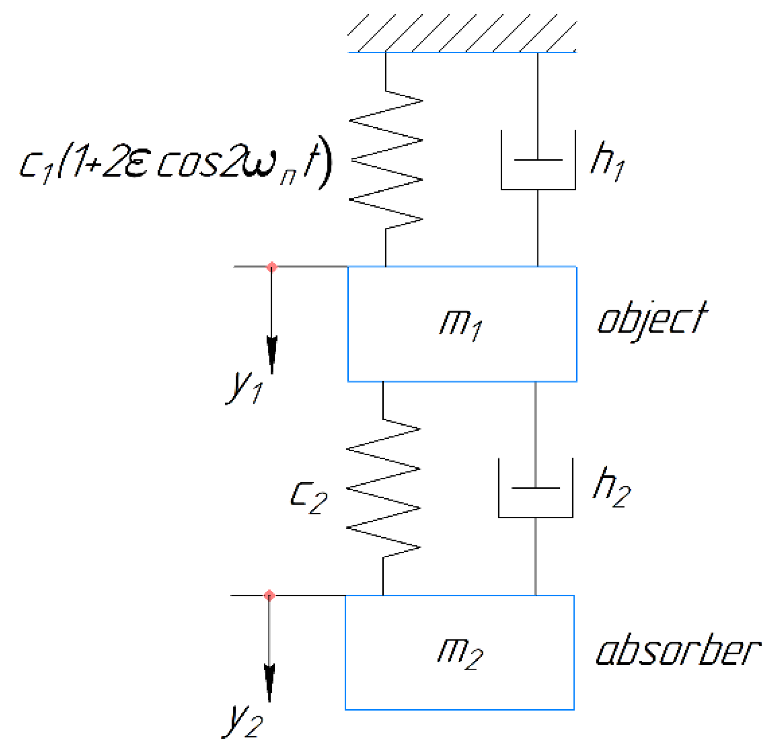
The vibrations of a double-mass system, including an object with variable stiffness and a dynamic vibration damper, can be considered according to the design scheme presented in Figure 1.
Vibration equations have the form:
where , , are the vibration displacements, velocities, and accelerations of the object and the dynamic vibration damper, respectively; are the reduced values of the mass, damping, and stiffness of the object; is the absorber mass; are the stiffness and damping of the absorber–object connection; are the squares of the partial frequencies; equals the mass ratio; is the excitation coefficient. is the frequency of the parametric excitation; t is time.
Substituting into Equation (1) the solution in the form:
where a1, b1, a2, and b2 are the coefficients of the corresponding functions.
After the substitution of expression (2) into Equation (1), the vanishing of the determinant of this system is the condition for the existence of a periodic solution of Equation (1).
After introducing the dimensionless factors , , , , and simplifying equal transformations, we obtain:
This expression allows for finding the excitation coefficient at the boundary of the stability region:
An unlimited increase in occurs at and . These conditions determine the values of the parameters of the dynamic vibration damper, under which the occurrence of parametric resonance is impossible, namely: the partial natural frequency of the damper must be equal to the frequency of the parametric perturbation, and the inelastic resistance of the damper-to-object connection must be as low as possible.
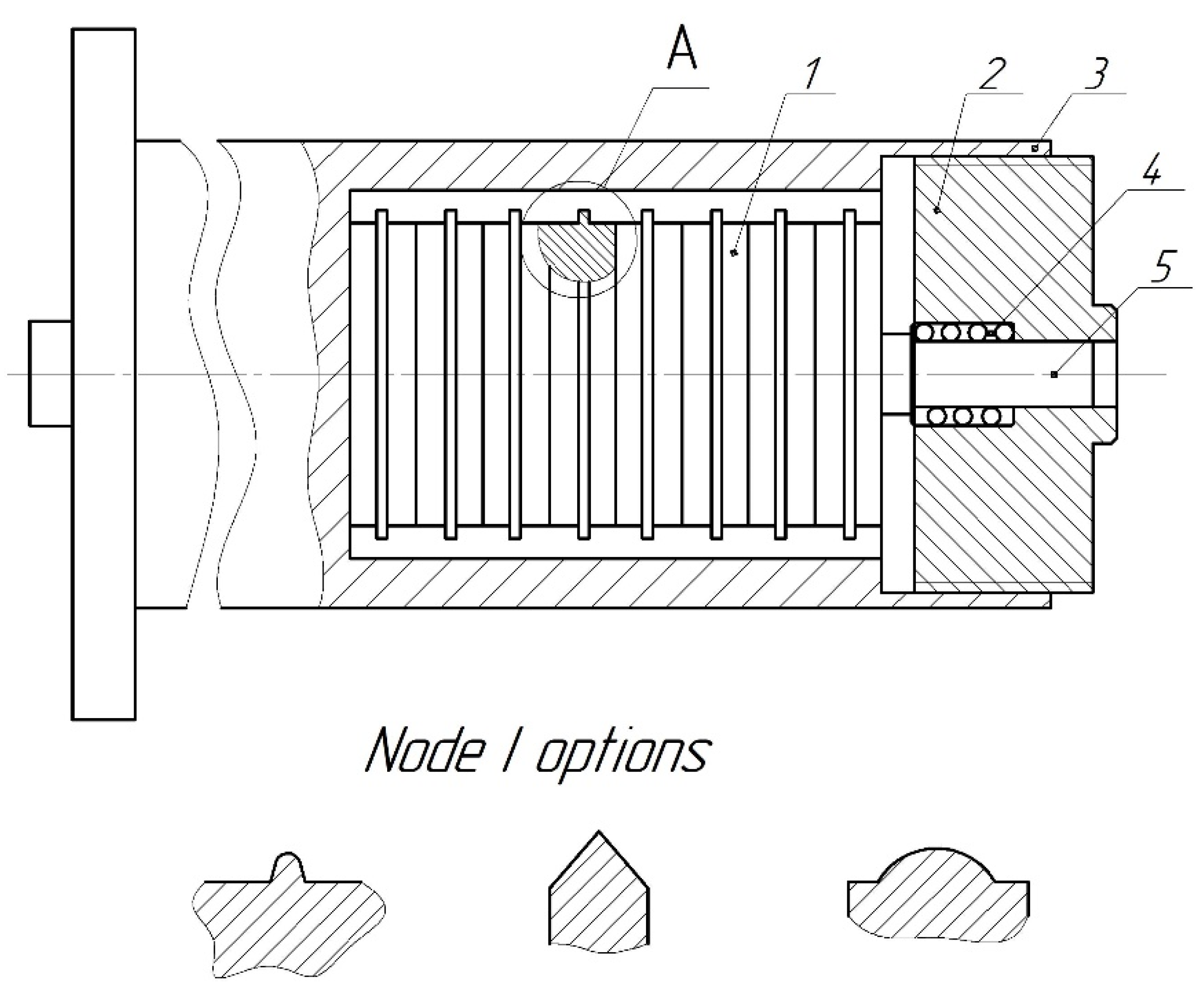
To determine the direction of action of shock pulses transmitted by the damper elements to the boring bar, the design of dampers (Figure 2) with annular protrusions on the disks was studied.
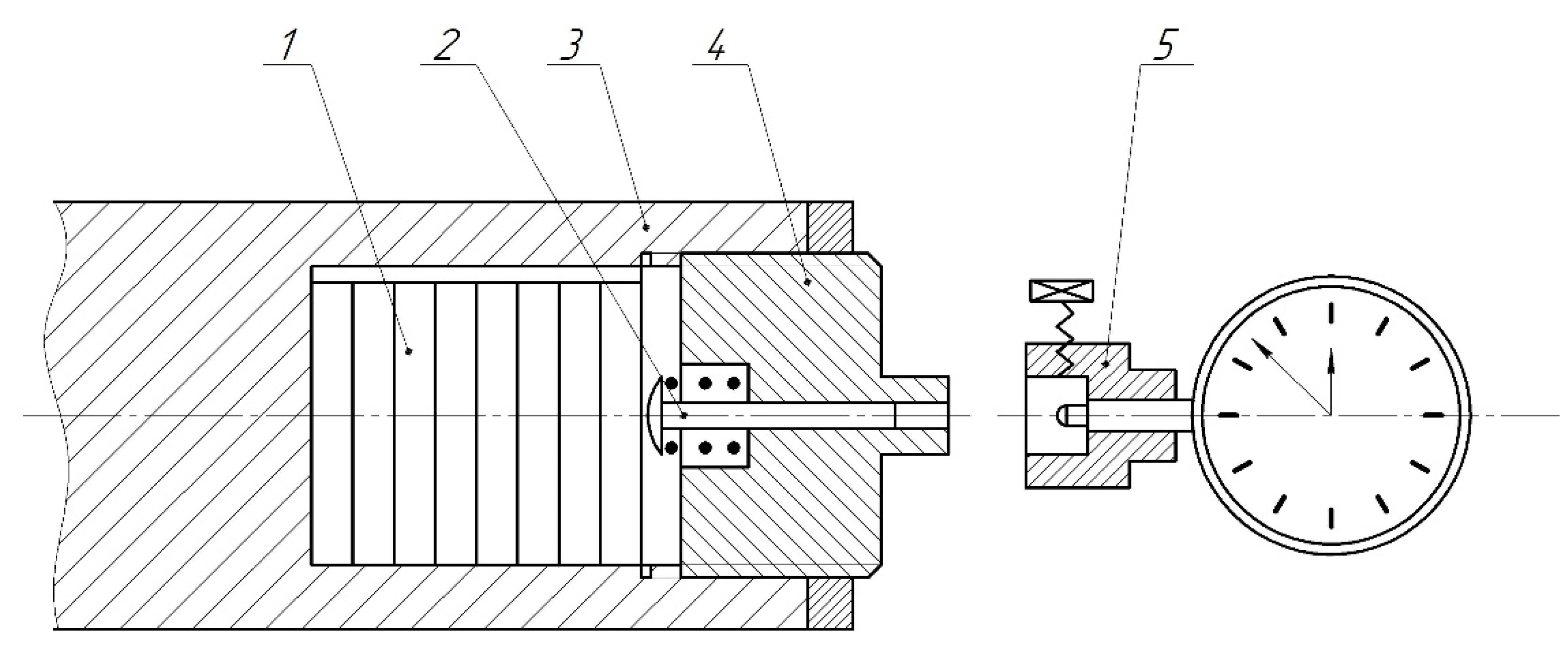
The vibration damper with annular protrusions on the discs 1 is compressed by a spring 4 through a pusher 5. The spring is held by a threaded cap 2, and when it is screwed into the body of the boring bar, the axial compression force N increases. The position of the cover is fixed by a lock nut 3. To determine the direction of action of shock pulses transmitted by the elements of the absorber to the boring bar, a design of a dynamic absorber with annular protrusions on the disks was made. The vibration absorber under study is shock-dynamic and makes it possible to optimize the shock characteristics. It is known that the effect of vibration damping depends significantly on the characteristics of the shock pulse. To increase the impact efficiency, the shock pulse vector is aligned with the axis of symmetry of the disk and its center of gravity. The impact surface of the disk is located in the middle section of the cylindrical surface and is made in the form of an annular protrusion. The shape of the transverse section of the protrusion, which affects the size of the contact area during collisions, is chosen empirically, depending on the efficiency of vibration damping. With optimal grip force, the discs can only move in the direction of the cutting force. The cross-sectional shape of the protrusion and the width of the platform, along which contact is made during impact, is selected depending on the material characteristics from which the disks are made. Note that the shape of the protrusion in the form of an acute angle provides the best damping of the shock pulse. The other two forms of protrusions increase damping in the absorber. The presence of friction in the damper weakens the damping effect. At the same time, the presence of attenuation will expand the frequency range at which the effect of oscillation damping is manifested. When testing the vibration damper, the axial compression forces were determined using a calibration device (Figure 3). When the axial compression force of spring 2, transmitted to disks 1, is changed, pusher 3 moves in the hole of the threaded cover 4. The magnitude of this movement is measured by a dial indicator installed in body 5 of the device, which is fixed on the shank of the threaded cover during adjustment. The device is calibrated by loading the pusher through a dynamometer, with the threaded cover removed from the boring bar.
The efficiency of the dynamic damper was evaluated in two ways: by determining the frequency response of the boring bars ( and 50 mm; = 6–8) and by measuring the vibrations of the boring bars ( = 15, 25, 50, and 70 mm) during boring.
3. Results
3.1. Experimental Results of Dynamic Vibration Dampers for Boring Discontinuous Surfaces
The dependence of the amplitude Ad of vibrations of boring bars with a dynamic vibration damper on the number of damper elements (Figure 4) is nonmonotonic for both test methods. Using a dynamic vibration damper with an optimal value of n equal to 8 leads to a decrease in the vibration amplitude during cutting by a factor of 3–5 compared to a single-element damper.
When studying the frequency characteristics, the ratio of the maximum values , where A0 is the amplitude of vibrations in the system without a damper, is taken as a measure of the efficiency of a dynamic vibration damper. By changes in efficiency: with a joint variation of the diametrical clearance and the force of axial compression of the disks, the values of these parameters were set.
The conditions for effectively using a dynamic vibration damper to process discontinuous surfaces are studied. To study the vibration damper under the conditions of the excitation of parametric resonances alone, we find that the maximum efficiency of the dynamic vibration damper is achieved with its damping coefficient negligible. This result is consistent with the theoretical conclusion (Equation (4)). When the constant component of the cutting force, which leads to parametric excitation of forced vibrations, is included in the consideration, we obtain a non-zero optimal value of the damping coefficient for the linear model of the dynamic vibration damper. The value of obtained in the simulation is approximately 30% less than that calculated by Den Hartog [23]. When studying the frequency characteristics, the ratio of values , where A0 is the vibration amplitude in the system without a damper, is taken as a measure of efficiency.
Full-scale tests of the dynamic damper during the boring of samples with a discontinuous surface were performed by varying the compression force of the disks and the diametric clearance. The results of these tests (Table 1) show that = 15–17 N and somewhat more than when boring solid surfaces and 2bopt = 0.2–0.4 mm. The vibration amplitude of the boring bar, with an installed absorber with optimized parameters, is reduced by about a third.
Table 1 shows the values of the oscillation amplitudes of the boring bar when varying the values of the compression forces and the diametral clearance (hole diameter d = 30 mm, six equally spaced grooves, steel C45, cutting depth t = 0.1 mm, cutting speed v = 200 m/min, and axial feed s = 0.04 mm/rev).
Single-element dynamic vibration dampers reduce the amplitude of vibrations at resonance and increase the limiting compliance of the boring bar by 3–4 times and the multi-element dampers by 5–10 times.
3.2. Airflow Supply to the Cutting Area
Cantilever boring bars with axial and radial holes for supplying cutting fluid or air to the cutting zone are widely used in finishing and boring machines. Such boring bars provide not only increased cooling efficiency of the cutting tool but also the removal of chips from the cutting zone. There are also known proposals to use the reaction of the jet flowing from the boring bar to balance the cutting force. However, the tool’s characteristics and the workpiece’s interaction with the medium flowing out of the boring bar are poorly understood.
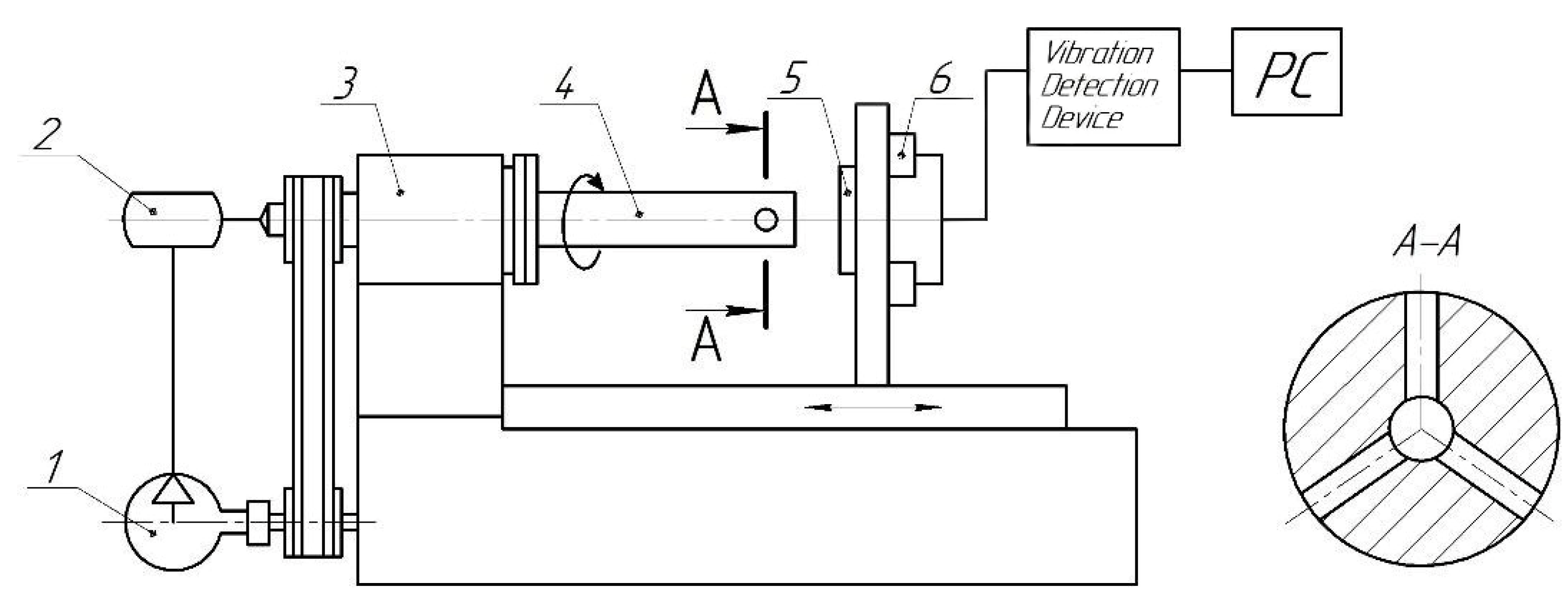
The experimental stand (Figure 5) includes a special boring bar 4 (d1 = 26 mm, l1/d1 = 6.5) with a central axial hole and three radial holes equally spaced from each other, located near the cutter. The boring bar is installed on the spindle head 3 of the finishing and boring machine model 2706B.
The number of outlets can be changed using screw plugs. The air supplied to the cutting zone enters the boring bar from compressor 1 through receiver 2, equipped with a pressure sensor and a hollow spindle. The pressure P at the receiver outlet varied from 0 to 500 kPa in increments of 50 kPa at a constant air flow rate. The inductive sensor 6 measured the elastic displacements of the free end of the boring bar in the presence or absence of the processed sample 5. The signal is transmitted to the PC through the Vibration Detection Device.
The elastic displacements were measured when air flowed through one hole to study the constant component of the force of interaction between the boring bar and the flow. The displacements at the exit of air into the atmosphere and into the gap between the sample’s inner surface and the boring bar’s outer surface were compared. The outlet was installed in the middle part of the sample, the length of which was 30 mm. Measurements with and without rotation of the boring bar were carried out by varying the air pressure and gap.
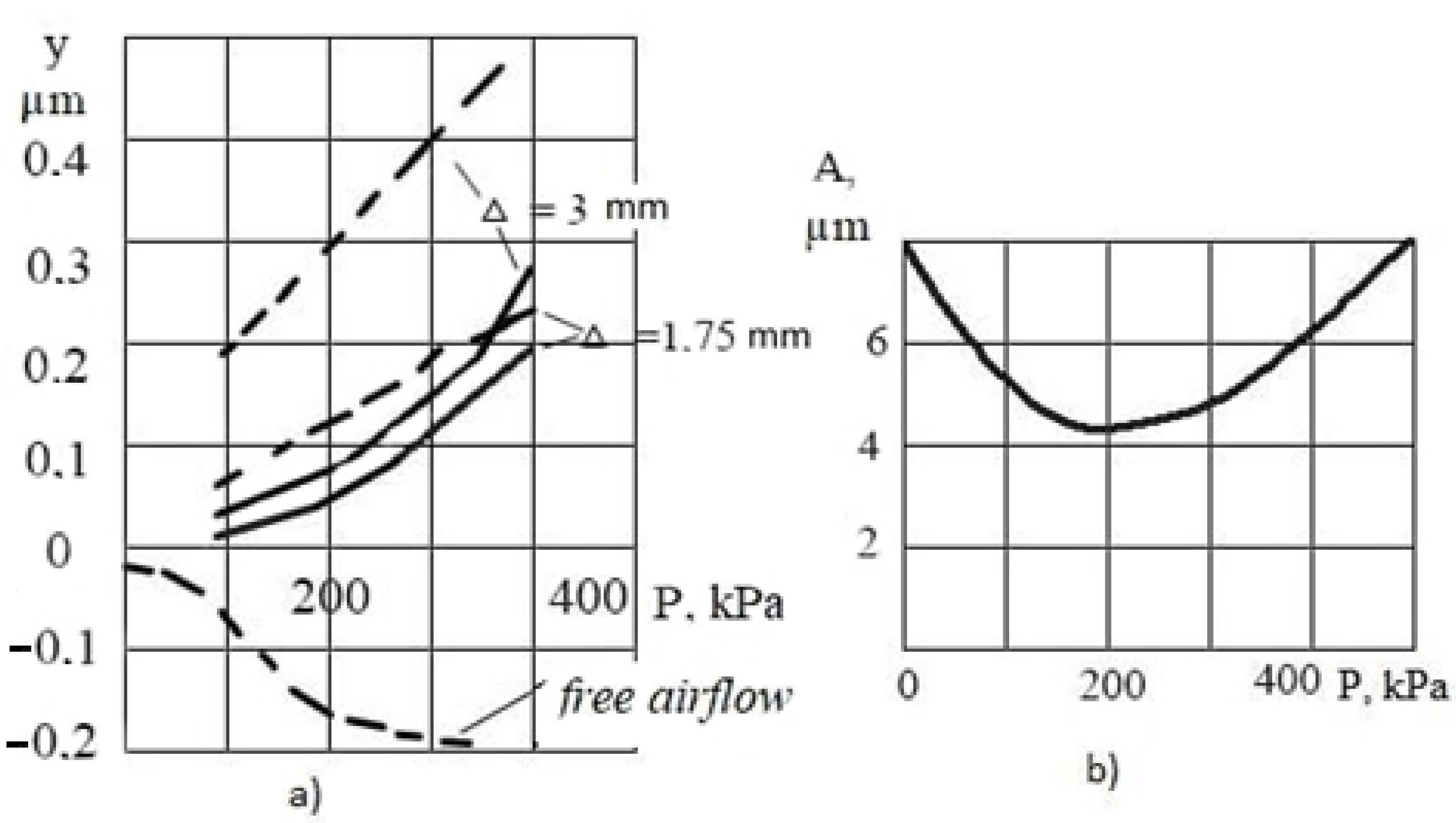
The dependence of elastic displacements y on pressure P at different values of the gap ∆ (Figure 6a) shows that the displacements are directed towards the jet outflow from the boring bar.
As the gap increases, the displacements increase. The rotation of the boring bar leads to a decrease in displacements and the manifestation of the nonlinearity of their dependence on pressure. When the outlet of the boring bar is located outside the sample and the free flow of air into the atmosphere, the elastic displacements are directed opposite to the outflowing flow since the reaction force of the jet causes them. When air flows into the gap between the boring bar and the sample, the pressure drop in the flow creates a force that changes the sign of the displacement.
The conditions of the air outflow and the direction of the force of interaction of the boring bar with the flow during boring change since the movement of the feed leads to a change in the position of the outlet of the boring bar relative to the sample. Therefore, when air flows out through one hole, the force of the interaction of the boring bar with the airflow cannot balance the cutting force along the entire length of the machining, a result of which is that the machined surface deviates from cylindricity, and the use of boring bars with one outlet is irrational. The force of the interaction of the boring bar with the flow does not cause the machined surface to deviate from cylindricity when air flows out through several holes equidistant from each other in one cross-section of the boring bar. The valuable effect of the airflow for such a boring bar increase with increasing damping. With the introduction of the boring bar into the sample hole without an air supply, the value of the logarithmic vibration decrement δ = 0.10 was measured. The measurements δ when air flows through three holes show that with increasing pressure, the logarithmic decrement of vibrations increases, reaching large values δ = 0.23 when flowing into the gap between the boring bar and the boring hole–Δ.
The boring bar was equipped with a boring tool made of Elbor-R. Cylindrical holes with a diameter of 30 mm were machined in samples made of GI18 cast iron at a cutting speed of 250 m/min, a feed rate of 0.04 mm/rev, and a depth of cut of 0.1 mm. The presence of a minimum in the dependence of the amplitude of vibrations of the boring bar during cutting on the air pressure at the receiver outlet at P = 250 kPa was established (Figure 6b). The transition from processing without air supply to processing at optimal pressure leads to a decrease in the amplitude of vibrations by 3–4 times and a decrease in the height of the micro-roughness of the treated surface from 3.0 to 1.1 µm (l/d = 10). In this case, the deviation from roundness reaches values of 1–3 µm.
3.3. Excitation of Vibrations Tangential to the Treated Surface
The results of the studies of the connectivity of the vibration modes that occur during boring and milling make it possible to control the vibrations normal to the machined surface by excitation of vibrations directed tangentially to this surface and not generate machining errors.
A positive effect of axial vibrations and the possibility of damping self-vibrations by forced vibrations are known. However, only a one-dimensional model of interacting vibrations is considered, and the nature of the interaction of various spatial vibration modes remains unexplored. For example, it is unclear what characteristics of damping vibrations make it possible to excite vibrations normal to the treated surface. A number of experiments have been carried out to address these issues.
The influence of the vibrations of fixture 2 (x–vibrations) in the feed direction on normal to the surface to be machined y–vibrations of the boring bar 6 was studied on the stand (Figure 7). Inductive sensors 3 and 4 of the vibrations of the fixture and the boring bar are connected to a PC through an amplifier of the vibration detection device, on which pulses from the spindle speed indicator 5 are also recorded.
The samples of steel C45 were bored at a depth of cut of 0.1 mm and a feed rate of 0.02 mm/rev with a carbide cutter, the tip of which was blunted to ensure self-excitation in the system of stable y-vibrations of the boring bar. The rotation frequency varied between 1200–1800 rpm in increments of 50 rpm. The frequency fx varied widely, including the frequency of self-vibrations fy.
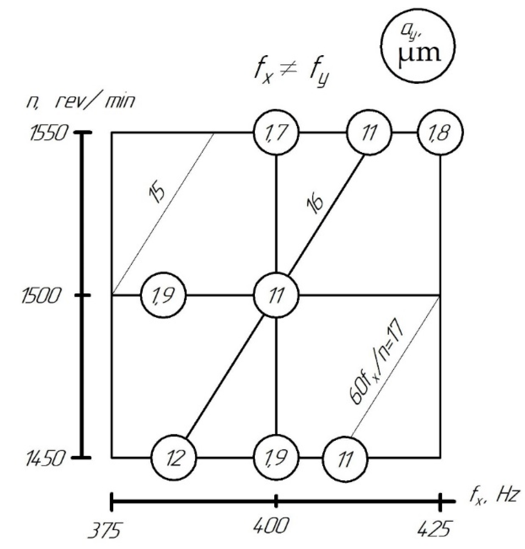
Intense self-vibrations with an amplitude of 10–15 µm, accompanied by a characteristic sound, were observed in the system under one of the following conditions: (a) with the amplitude of the forced vibrations of the fixture or sufficiently small (ax < 2 µm); (b) when the frequency fx of the forced vibrations of the device coincides with the natural frequency fy of the vibrations of the boring bar, (c) at a frequency fx that is a multiple of the spindle speed, i.e., upon reaching the equality
These results are illustrated by a diagram (Figure 8), on which the amplitudes ɑy are shown in circles for various combinations of forced vibrations and rotation frequencies.
Note that the x–vibrations change the cross-section of the cut layer, leading to a change in the parameters of the cutting process; in this case, parametric vibrations develop. The changes in the cutting factor generate additional “friction forces” proportional to the parametric excitation factor. Therefore, the suppression of self-vibrations is possible at sufficiently large, i.e., for sufficiently ax.
Condition (b) excludes the number of available frequencies of the forced vibrations that correspond to the resonance of the boring bar. Condition (c) shows that the useful effect of forced vibrations depends on the variability of the section of the cut layer.
If the amplitude of the forced axial vibrations exceeds a specific value (for the studied system—2 μm), fx ≠ fy and (k is an integer), then the amplitudes of self-vibrations decrease by 6–7 times. Thus, vibrations in directions tangential to the surface to be machined are capable of detuning and suppressing the vibrations excited by the regeneration of the “trace” and the “primary” self-vibrations generated by the nonlinearity of the elements of the closed dynamic system of the machine.
4. Discussion
The paper explores three ways to improve the dynamic quality of cantilever boring bars, aimed at expanding the technological capabilities of the fine boring operation. The dynamics of special cantilever boring bars under difficult cutting conditions (interrupted cutting, boring of deep holes with the ratio l/d > 3 to l/d = 12, and under self-vibrations) have been studied. All three methods provide damping of vibrations and increase the vibration resistance of the tool. The tasks formulated in this work are aimed at achieving the set goal.
Why was the vibration damping method chosen using vibration dampers? Indeed, even from a brief review of the literature, it is clear that numerous studies have been carried out on the designs, principles of operation, calculation, and tuning of dynamic vibration dampers. However, for optimal tuning of vibration dampers, you should know which vibrations need to be damped.
Inertial dynamic dampers are used to suppress harmonic as well as narrow-band random vibrations. These dynamic dampers are tuned to the frequency of the suppressed vibrations by setting the stiffness of the elastic element and the mass of the damper. Under the conditions of the action of broadband vibration effects, dynamic dampers with friction and vibration absorbers are used. For dynamic shock dampers, the gap size and mass are selected depending on the frequency and amplitude of the disturbing force. Dynamic shock dampers are most often used for boring bars. At the same time, their multi-element executions are the most effective. Thus, to tune dynamic dampers, it is necessary to understand the characteristics of the influences that cause vibrations. In addition to force and external kinematic effects on the elastic system of the machine, the sources of vibrations are parametric disturbances.
These features give rise to a number of computational problems. One of these problems—the conditions for setting up a dynamic vibration damper to suppress parametric resonance—is solved in this work. Periodic repetitions of cutting in and out of the tool during interrupted cutting lead to the variability of the parameters of the elastic system, the cutting process, and other working processes. In this case, vibrations of a higher level are more excited than with continuous cutting. For a shock-dynamic vibration damper, the conditions for optimal tuning (with changes in the compression forces of the disks and diametrical clearance) make it possible to reduce the amplitude of bending vibrations by a factor of three compared to boring without a vibration damper. The conditions for optimal tuning when suppressing parametric and forced vibrations are qualitatively close. It has been established that the highest vibration-damping efficiency is achieved using multi-element shock-dynamic devices. Single-element shock vibration dampers increase the value of the limiting compliance of the boring bar by 3–4 times and multi-element ones by 5–10 times.
Additional experiments are needed to improve the dynamic properties of boring bars with a tuned vibration damper during interrupted cutting. As one of the options for such experiments, there can be a constructive increase in the torsional compliance of a boring bar with a built-in vibration damper. It will increase the plunging time (transient time), shock absorption will occur, and the wear of the cutting blades will decrease. In the development of the experiments performed, it is necessary to determine the conditions for excluding “stagnant zones” in multi-element dynamic dampers when the masses work as a whole. It is necessary to study the influence of the shape of the cross-sections of the disks on the process of friction between them.
The use of the developed vibration-resistant boring bars with a source of air under pressure in the cutting zone provides a significant expansion of the technological capabilities of boring machines: fine boring is feasible with a hole-to-diameter ratio of up to 12 with a roughness Ra = 1–1.3 µm and a roundness deviation within 2–3 µm. This work studied the outflow of air through one and three holes. The diameters of the radial holes were 2, 4, and 8 mm and were equally spaced. Smaller values of vibration amplitudes were realized at a diameter of radial holes equal to 8 mm. The diameter of the central hole for a boring bar with a diameter of 30 mm was 10 mm.
It is known that at l/d > 4, the cantilever boring bars lose vibration resistance. Cutting becomes unstable, cutting blades are prone to chipping, and the wear of cutting inserts increases significantly. To combat this phenomenon, it is necessary to manufacture boring bars manufactured from hard alloys, which are very unprofitable. As shown by the described experiments, boring bars with airflow make it possible to bore deep holes. This possibility is provided by a significant increase in the logarithmic swing decrement (up to δ = 0.25) when flowing through three holes (d = 8 mm) compared to the mode without flow when flowing through one hole δ = 0.1.
The positive results of the experiment suggest the possibility of using the outflow of a more viscous working medium, for example, industrial oil, instead of an airflow. Such a replacement will provide an increase in the logarithmic decrement, a decrease in the amplitude of the vibrations of the boring bar, and an increase in the quality of processing. Naturally, it will be necessary to protect against the working environment splashing.
The third way to suppress the vibrations of cantilever boring bars is proposed based on the coherence of the vibration modes that occur during boring. Therefore, it becomes possible to control movements normal to the treated surface by exciting vibrations directed tangentially to the surface. It was established that, in this case, it is possible to suppress the self-vibrations normal to this surface, both regenerative and generated by the nonlinearities of the dynamic system.
On a special stand, the effect of the vibrations of the fixture (x-vibrations) in the feed direction on the bending y-vibrations of the boring bar, which are normal to the surface to be machined, was studied. Samples of steel were installed in the fixture and bored at a depth of cut of 0.1 mm and a feed rate of 0.02 mm/rev with a blunt-tipped carbide cutting blade to ensure stable self-vibrations of the boring bar (y-vibrations). The rotational speed has changed within 1200–1800 rpm. The frequency fx was varied in a wide range, including the self-oscillation frequency fy. In the experiment, the conditions for the excitation of self-vibrations with an amplitude of 10–15 μm were determined. The results of the experiments proved that if the amplitude of forced axial vibrations has a certain boundary value (for the system under study = 2 μm), fx ≠ fy and 60fx/n = k + , then the amplitude of self-vibrations decreases by 6–7 times.
The roughness of the treated surface is Ra = 1 µm. Vibration damping occurs due to the variability of the cutting factor. In this case, additional “friction forces” appear, which are proportional to the vibration-damping coefficient. The suppression of vibrations is achieved at large values of the attenuation coefficient, i.e., with sufficiently large cut sections—ah. Thus, it has been established that the suppression of self-vibrations upon the excitation of forced axial vibrations depends on the variability of the section of the sheared layer.
It should be noted that the usefulness of the results of these experiments lies in the unconditional sharp decrease in the wear of the cutting blades. The experiments should be additionally performed to quantify wear, although preliminary experiments showed a decrease in wear of the cutting insert per 1000 m by approx. three times compared to cutting without applying additional vibrations (when boring steel samples).
It should also be clarified that such vibratory cutting for fine finishing boring is not described in the technical literature. However, it is often used for non-precision machining in turning, milling, drilling, etc. Further research on the errors in finishing boring is also necessary.
5. Conclusions
In this work, three methods for damping the vibrations of special cantilever boring bars for fine boring are studied in special cutting conditions (when machining deep holes, intermittent boring, and during self-vibrations). To expand the technological capabilities of fine boring, it is necessary to increase the dynamic quality of the cantilever tool. The conditions for setting up a dynamic vibration damper to suppress parametric resonance are analytically determined: the partial natural frequency of the damper must be equal to the frequency of parametric excitation, and the inelastic resistance of the damper-to-object connection must be as low as possible.
The conditions for optimal tuning of vibration dampers in suppressing parametric forced vibrations are qualitatively close. The highest efficiency of vibration damping is achieved when using multi-element shock-dynamic devices.
In interrupted cutting, the conditions for optimal setting are:
- -
- A multi-element vibration damper for the boring bar, which reduces the amplitude of bending vibrations by three times;
- -
- Number of elements (masses) of the absorber n = 8;
- -
- The dependence of the boring bar’s oscillation amplitudes on the disks’ axial compression force and the diametrical clearance value (Nopt = 15 N, ∆ = 0.2–0.4 mm).
The features of the interaction of the airflow flowing from the radial holes in the boring bar with the workpiece are studied. The values of pressures that provide the minimum level of fluctuations and the smallest processing errors are determined. At a pressure of 200–400 kPa and a gap between the boring bar and the sample of approx. 2 mm, the values of the logarithmic vibration decrement increase to 0.25. In this case, the vibration amplitude of the boring bar decreases from 7–8 µm to 1.5–2 µm and the roughness of the treated surface Ra = 1–2 µm.
The possibility of effectively reducing the bending vibrations that are normal to the machined surface under the action of forced axial vibrations in the feed direction has been studied. The conditions for damping the amplitudes of self-vibrations up to seven times compared to vibrations of the boring bar without forced axial vibrations (5 μm) are determined. In experiments on the boring steel samples without axial vibrations, the amplitude reached values of 15–20 µm.
All of the above problems should be attributed to non-stationary issues of dynamics since, during processing, there is variability in the parameters of the elastic system and the cutting process. Due to the variability of the parameters, such vibrations are called parametric. The non-stationarity of the dynamic systems of machine tools and parametric vibrations are characteristic of almost all metal cutting problems. These problems are not exhausted by the content of this work. Still, its results allow us to outline a number of directions for developing the dynamics of systems with variable parameters that are useful for mechanical engineering technology.
Author Contributions
Conceptualization, A.O., V.I. and A.B.; methodology, G.O.; software, I.P.; formal analysis, G.O., I.P.; investigation, A.O.; resources, J.T.; data curation, A.O.; writing—original draft preparation, A.O. and G.O.; writing—review and editing, A.B., V.I. and I.P.; visualization, A.B.; supervision, V.I.; project administration, J.T.; funding acquisition, J.T. All authors have read and agreed to the published version of the manuscript.
Funding
The research was carried out within the project “Improvement of the Production Planning by Implementation of the Computer-Aided Fixture Design System” within the Joint Ukrainian–Slovak R&D Projects for the period of 2022–2023 granted by the Slovak Research and Development Agency (SK-UA-21-0060) and the Ministry of Education and Science of Ukraine (State reg. no. 0122U002657).
Institutional Review Board Statement
Not applicable.
Informed Consent Statement
Not applicable.
Data Availability Statement
The data presented in this study are available on request from the corresponding author.
Acknowledgments
The research was partially carried out within the project "Intensification of production processes and development of intelligent product quality control systems in smart manufacturing" (State reg. no. 0122U200875, Ministry of Education and Science of Ukraine). The research was partially supported by the Research and Educational Center for Industrial Engineering (Sumy State University) and International Association for Technological Development and Innovations.
Conflicts of Interest
The authors declare no conflict of interest.
References
- Chockalingam, S.; Natarajan, U.; Selvam, M.; Cyril, A.G. Investigation on Machinability and Damping Properties of Nickel–Phosphorus Coated Boring bar. Arab. J. Sci. Eng. 2016, 41, 669–676. [Google Scholar] [CrossRef]
- Song, Q.; Shi, J.; Liu, Z.; Wan, Y.; Xia, F. Boring bar with constrained layer damper for improving process stability. Int. J. Adv. Manuf. Technol. 2016, 83, 1951–1966. [Google Scholar] [CrossRef]
- Suyama, D.I.; Diniz, A.E.; Pederiva, R. The use of carbide and particle-damped bars to increase tool overhang in the internal turning of hardened steel. Int. J. Adv. Manuf. Technol. 2016, 86, 2083–2092. [Google Scholar] [CrossRef]
- Thomas, M.D.; Knight, W.A.; Sadek, M.M. Impact damper as a method of improving cantilever boring bars. J. Eng. Ind. Aug 1975, 97, 859–866. [Google Scholar] [CrossRef]
- Thorenz, B.; Friedrich, M.; Westermann, H.-H.; Döpper, F. Evaluation of the influence of different inner cores on the dynamic behavior of boring bars. Procedia CIRP 2019, 81, 1171–1176. [Google Scholar] [CrossRef]
- Rajak, D.; Pagar, D.; Menezes, P.; Linul, E. Fiber-Reinforced Polymer Composites: Manu-facturing, Properties, and Applications. Polymers 2019, 11, 1667. [Google Scholar] [CrossRef] [PubMed] [Green Version]
- Bruckner, W. CFK: Hohe Kosten blockieren Durchbruch am Massenmarkt. 2018. Available online: https://www.ingenieur.de/technik/fachbereiche/werkstoffe/cfk-hohe-kosten-blockieren-durchbruch-am-massenmarkt/ (accessed on 12 October 2022).
- Ren, Y.; Zhao, Q.; Liu, Y.; Ma, J. Analysis of bending vibration characteristics of rotating composite boring bar. J. Phys. Conf. Ser. 2019, 1303, 012147. [Google Scholar] [CrossRef]
- Sørby, K.; Østling, D. Precision turning with instrumented vibration-damped boring bars. In Proceedings of the 8th CIRP Conference on High Performance Cutting, Budapest, Hungary, 25–27 June 2018; pp. 666–669. [Google Scholar]
- Auleley, M.; Thomas, O.; Giraud-Audine, C.; Mahé, H. Enhancement of a dynamic vibration absorber by means of an electromagnetic shunt. J. Intell. Mater. Syst. Struct. 2020, 32, 331–354. [Google Scholar] [CrossRef]
- Hovorun, T.; Khaniukov, K.; Varakin, V.; Pererva, V.; Vorobiov, S.; Burlaka, A.; Khvostenko, R. Improvement of the physical and mechanical properties of the cutting tool by applying wear-resistant coatings based on Ti, Al, Si, and N. J. Eng. Sci. 2021, 8, C13–C23. [Google Scholar] [CrossRef]
- Otto, A.; Radons, G. The influence of tangential and torsional vibrations on the stability lobes in metal cutting. Nonlinear Dyn. 2015, 82, 1989–2000. [Google Scholar] [CrossRef]
- Lawrance, G.; Paul, P.S.; Varadarajan, A.S.; Vasanth, X.A.; Raj, S.B. Suppression of Tool Vibration in Boring Process: A Review. J. Inst. Eng. India Ser. C 2019, 100, 1053–1069. [Google Scholar] [CrossRef]
- Ramesh, K.; Alwarsamy, T.; Jayabal, S. Investigation of chatter stability in boring tool and tool wear prediction using neural network. International J. Mater. Prod. Technol. 2013, 46, 47–70. [Google Scholar] [CrossRef]
- Ramesh, K.; Alwarsamy, T.; Jayabal, S. ANN prediction and RSM optimization of cutting process parameters in boring operations using impact dampers. J. Vibroeng. 2012, 14, 1160–1175. [Google Scholar]
- Chockalingam, S.; Natarajan, U.; George Cyril, A. Damping investigation in boring bar using hybrid copper-zinc particles. J. Vib. Control. 2017, 23, 2128–2134. [Google Scholar] [CrossRef]
- Lu, Z.; Lu, X.; Masri, S.F. Studies of the performance of particle dampers under dynamic loads. J. Sound Vib. 2010, 329, 5415–5433. [Google Scholar] [CrossRef]
- Ehsan, M.M.E.; Yousefi-Koma, A.; Ehyaei, D. Optimal design of an impact damper for a nonlinear friction-driven oscillator. Int. J. Math. Models Methods Appl. Sci. 2008, 2, 236–243. [Google Scholar]
- Rubio, L.; Loya, J.A.; Miguélez, M.H.; Fernández Sáez, J. Optimization of passive vibration absorbers to reduce chatter in boring. Mech. Syst. Signal Process. 2013, 41, 691–704. [Google Scholar] [CrossRef] [Green Version]
- Ivanov, V.; Pavlenko, I.; Kuric, I.; Kosov, M. Mathematical modeling and numerical simulation of fixtures for fork-type parts manufacturing. In Industry 4.0: Trends in Management of Intelligent Manufacturing Systems; Knapcikova, L., Balog, M., Eds.; EAI/Springer Innovations in Communication and Computing; Springer: Cham, Switzerland, 2019; pp. 133–142. [Google Scholar] [CrossRef]
- Ozlu, E.; Budak, E. Analytical modeling of chatter stability in turning and boring operations Part I: Model development. Trans. ASME 2007, 129, 726–732. [Google Scholar] [CrossRef]
- Ozlu, E.; Budak, E. Analytical modeling of chatter stability in turning and boring operations-Part II: Experimental verification. J. Manuf. Sci. Eng. 2007, 129, 733–739. [Google Scholar] [CrossRef]
- Den Hartog, J.P. Mechanical Vibrations; Dover Publications: New York, NY, USA, 1985. [Google Scholar]
Figure 1.
The design scheme of the double-mass system with the variable-stiffness object and the dynamic vibration damper.
Figure 1.
The design scheme of the double-mass system with the variable-stiffness object and the dynamic vibration damper.

Figure 2.
Shock damper with protrusions on the disks.

Figure 3.
Multi-element dynamic vibration damper with a device for calibrating the axial compression force.
Figure 3.
Multi-element dynamic vibration damper with a device for calibrating the axial compression force.

Figure 4.
Dependence of the vibration amplitude on the number of elements of the dynamic vibration damper: 1—according to frequency response; 2—when boring; n—number of elements; mm, mm; mm, mm.
Figure 4.
Dependence of the vibration amplitude on the number of elements of the dynamic vibration damper: 1—according to frequency response; 2—when boring; n—number of elements; mm, mm; mm, mm.

Figure 5.
Scheme of the stand for studying the action of the airflow substituted into the cutting zone.
Figure 5.
Scheme of the stand for studying the action of the airflow substituted into the cutting zone.

Figure 6.
Dependence of elastic displacements (a) and vibration amplitudes of the boring bar during a boring (b) on pressure P: ![Machines 11 00007 i001]() —the boring bar rotates;
—the boring bar rotates; ![Machines 11 00007 i002]() —the boring bar does not rotate.
—the boring bar does not rotate.
 —the boring bar rotates;
  —the boring bar does not rotate.
Figure 6.
Dependence of elastic displacements (a) and vibration amplitudes of the boring bar during a boring (b) on pressure P: ![Machines 11 00007 i001]() —the boring bar rotates;
—the boring bar rotates; ![Machines 11 00007 i002]() —the boring bar does not rotate.
—the boring bar does not rotate.
—the boring bar rotates; —the boring bar does not rotate.
Figure 7.
Scheme of the stand for studying the damping of self-vibrations by vibrations in the feed direction.
Figure 7.
Scheme of the stand for studying the damping of self-vibrations by vibrations in the feed direction.

Figure 8.
Analysis of the conditions for damping self-vibrations.


Table 1.
Dependence of the oscillation amplitudes of the boring bar (µm) on the diametral clearance (2b) and the axial compression force of the disks (N) when boring a discontinuous surface.
Table 1.
Dependence of the oscillation amplitudes of the boring bar (µm) on the diametral clearance (2b) and the axial compression force of the disks (N) when boring a discontinuous surface.
| Diameter clearance 2b, mm | Oscillation amplitudes of the boring bar, µm | |||||
| With vibration damper for N | Without vibration damper | |||||
| 5 | 10 | 15 | 20 | 30 | 10 | |
| 0.1 | 8 | 7.5 | 5 | 5.5 | 7 | |
| 0.2 | 6 | 4 | 5 | 5 | 7 | |
| 0.3 | 5 | 3.5 | 3 | 4 | 5 | |
| 0.4 | 5 | 4 | 3.5 | 4.5 | 5.5–6 | |
| 0.5 | 6 | 6 | 4 | 6 | 8 | |
Disclaimer/Publisher’s Note: The statements, opinions and data contained in all publications are solely those of the individual author(s) and contributor(s) and not of MDPI and/or the editor(s). MDPI and/or the editor(s) disclaim responsibility for any injury to people or property resulting from any ideas, methods, instructions or products referred to in the content. |
© 2022 by the authors. Licensee MDPI, Basel, Switzerland. This article is an open access article distributed under the terms and conditions of the Creative Commons Attribution (CC BY) license (https://creativecommons.org/licenses/by/4.0/).
Share and Cite
MDPI and ACS Style
Oborskyi, G.; Orgiyan, A.; Ivanov, V.; Balaniuk, A.; Pavlenko, I.; Trojanowska, J. Improvement of the Dynamic Quality of Cantilever Boring Bars for Fine Boring. Machines 2023, 11, 7. https://doi.org/10.3390/machines11010007
AMA Style
Oborskyi G, Orgiyan A, Ivanov V, Balaniuk A, Pavlenko I, Trojanowska J. Improvement of the Dynamic Quality of Cantilever Boring Bars for Fine Boring. Machines. 2023; 11(1):7. https://doi.org/10.3390/machines11010007
Chicago/Turabian StyleOborskyi, Gennadii, Alexandr Orgiyan, Vitalii Ivanov, Anna Balaniuk, Ivan Pavlenko, and Justyna Trojanowska. 2023. "Improvement of the Dynamic Quality of Cantilever Boring Bars for Fine Boring" Machines 11, no. 1: 7. https://doi.org/10.3390/machines11010007
Note that from the first issue of 2016, this journal uses article numbers instead of page numbers. See further details here.