Article

Characterization of an Amorphous Titanium Oxide Film Deposited onto a Nano-Textured Fluorination Surface

1
Institute of Electro-Optical and Materials Science, National Formosa University, Huwei, Yunlin 63201, Taiwan
2
ITRI South, Industrial Technology Research Institute, Liujia Shiang, Tainan 73445, Taiwan
*
Author to whom correspondence should be addressed.
Materials 2016, 9(6), 429; https://doi.org/10.3390/ma9060429
Submission received: 6 May 2016 / Revised: 19 May 2016 / Accepted: 26 May 2016 / Published: 31 May 2016
(This article belongs to the Special Issue Selected Papers from ICASI 2016)

Abstract

:
The photocatalytic activity of an amorphous titanium oxide (a-TiOx) film was modified using a two-step deposition. The fluorinated base layer with a nano-textured surface prepared by a selective fluorination etching process acted as growth seeds in the subsequent a-TiOx deposition. A nanorod-like microstructure was achievable from the resulting a-TiOx film due to the self-assembled deposition. Compared to the a-TiOx film directly deposited onto the untreated base layer, the rate constant of this fluorinate-free a-TiOx film surface for decomposing methylene blue (MB) solution that was employed to assess the film’s photocatalytic activity was markedly increased from 0.0076 min−1 to 0.0267 min−1 as a mechanism for the marked increase in the specific surface area.

1. Introduction

Titanium oxide (TiOx) is one of the most popular materials in environmental purification, anti- or high-reflection coating, dye-sensitized solar cells, surface self-cleaning/antifogging functional coating, and biomedical engineering applications due to its chemical stability, optical transparency at visible wavelength, high refractive index, non-toxic nature, and low cost [1,2,3,4,5]. In terms of the photocatalytic activity, TiOx film is known to be influenced by its crystalline structure, specific surface area, and functional group incorporation [6,7]. Although the TiOx film with anatase structures has the best photocatalytic activity, the deposition and/or post-annealing temperature required to form anatase crystallinity is too high to limit such film applied to surface modification and packaging on the heat-sensitive substrates or devices. Accordingly, an effort was made to enhance the photocatalytic activity of an anatase-TiOx film at low temperature by realizing the p-n junction or doping with a specific dopant [8,9,10]. Alternatively, an amorphous TiOx film abundant in hydroxyl (O–H) functional groups on the film surface was found to be a promising substitute for exhibiting quality photocatalytic activity at a low temperature [11,12]. In our previous report, we developed a selectively fluorinated etching on the a-TiOx film to result in a nano-textured surface with the incorporation of fluorine ions [13]. Such film exhibited a high photocatalytic activity that was comparable to that of the TiOx film with an anatase structure and was applied to package the blue-light organic light emitting diode to result in a device with a self-cleaning function [14]. The apparent improvement on the film’s photocatalytic activity was a mechanism of the formation of the Ti–F functional group for facilitating the separation of the photo-produced charge couples and the increase in the reactants’ adsorption as a consequence of the large specific surface area. However, since the fluorine ion is not environment friendly for the most chemically reactive and electronegative of all the elements, it becomes increasingly necessary to prepare a fluorine-free surface of the a-TiOx film with the same photocatalytic activity by further optimizing the film’s specific surface area. Accordingly, the above-mentioned process should be improved to realize a quality a-TiOx film without the incorporation of the fluorine ions.
As the surface property of the a-TiOx film was modifiable by the selectively fluorinated etching, in this work, a base layer with such a nano-textured surface abundant in fluorine ions affecting the subsequently deposited a-TiOx film was studied. The growth mechanism of the resulting a-TiOx film with the fluorine-free surface prepared using this two-step deposition was elucidated through the observations of the associated surface and cross-section morphologies. The origin responsible for the improvement of the photocatalytic activity was characterized by an increase in the specific surface area and amounts of OH groups as conducted from the measurements of the surface roughness and chemical bond configuration.

2. Experimental Procedure

A 100-nm-thick hydro-generated a-TiOx film was deposited on silicon substrates (10 × 10 mm2) by a plasma-enhanced chemical vapor deposition (PECVD) system, using a titanium tetraisopropoxide [Ti(OC3H7)4, TTIP]-oxygen gas mixture. The deposition pressure, power, and gas flow rate of TTIP/O2 were controlled at 40 Pa, 100 W, and 120/20 sccm, respectively. A detailed system setup and deposition parameters have been described elsewhere [12]. Incorporating fluorine ions into the nano-textured surface on the a-TiOx film was achieved by pre-irradiating a UV light for 5 h through an anodic alumina membrane mask and then etching in the diluted hydrofluoric (HF) solution for a different time. The selective fluorination etching (hereafter abbreviated to SFE) has been addressed elsewhere [13]. A 100-nm-thick a-TiOx film using PECVD under the same deposition condition was then coated onto the base layer with surface nano-textures to realize the a-TiOx film surface free of the fluorine ions. In addition, another set of the a-TiOx film crystallized into anatase structures was prepared by post-annealing the un-treated a-TiOx film at 500 °C for 30 min under oxygen ambient (hereafter denoted as annealed TiOx film) as a comparison.
Film thickness of these a-TiOx films with and without the SFE treatment as well as prepared using the two-step deposition was measured using a surface profile system (Dektak 6M, Veeco, New York, NY, USA). Surface roughness was measured using atomic force microscopy (AFM, DI-3100, Veeco, New York, NY, USA) with the tapping mode. The surface and cross-section morphologies were observed by a field emission scanning electron microscope (FE-SEM, JSM-6700F, JEOL, Tokyo, Japan) operated at 3 kV. Fourier transform infrared spectrometry (FTIR, FT/IR-4100, JASCO, Halifax, NS, Canada) and X-ray photoelectron spectroscope (XPS, ULVAC-PHI, Quantera SXM, Kanagawa, Japan) with monochromatic Al Kα radiation were employed to examine the film’s chemical bonding states and surface bond nature. The photocatalytic activity for the a-TiOx and annealed TiOx films illuminated by the UV light with a constant intensity of 1 mW/cm2 was evaluated by the decolorization of a 20 ppm concentrated methylene blue (MB) solution using the UV-Vis spectrophotometer from the absorbance of the resulting solution at 665 nm under atmosphere ambient.

3. Results and Discussion

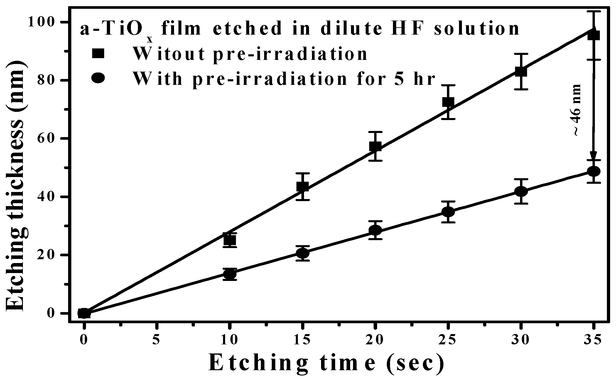
Figure 1 shows the etching thickness of the a-TiOx film with and without the UV light pre-irradiation for 5 h, and then immersed in the HF etching solution for different etching times. The etching thickness of the a-TiOx film treated by additive UV light pre-irradiation was apparently lower than the a-TiOx film directly etched by the HF solution. The less acidic surface of the a-TiOx film, as a consequence of the Ti(IV)−OH, transformed into a Ti(III)−OH group due to the generated electrons under UV light pre-irradiation, was responsible for the alleviation of the sequential etching process [13]. A large discrepancy occurred in the etching thickness between the a-TiOx films with and without the UV light pre-irradiation (approximately 46 nm) as the etching time reached 35 s, while at this time the 100-nm-thick a-TiOx film directly etched by the HF solution was almost completely removed, as shown in Figure 1. Because an apparent difference in the etching thickness of the a-TiOx films was obtainable from the fluorination etching with and without UV light pre-irradiation, a selective fluorination etching treatment on the a-TiOx film to modify its surface morphology was carried out by selectively shadowing the surface through a nano-sized mask with UV light pre-irradiation and then processing the fluorination etching.
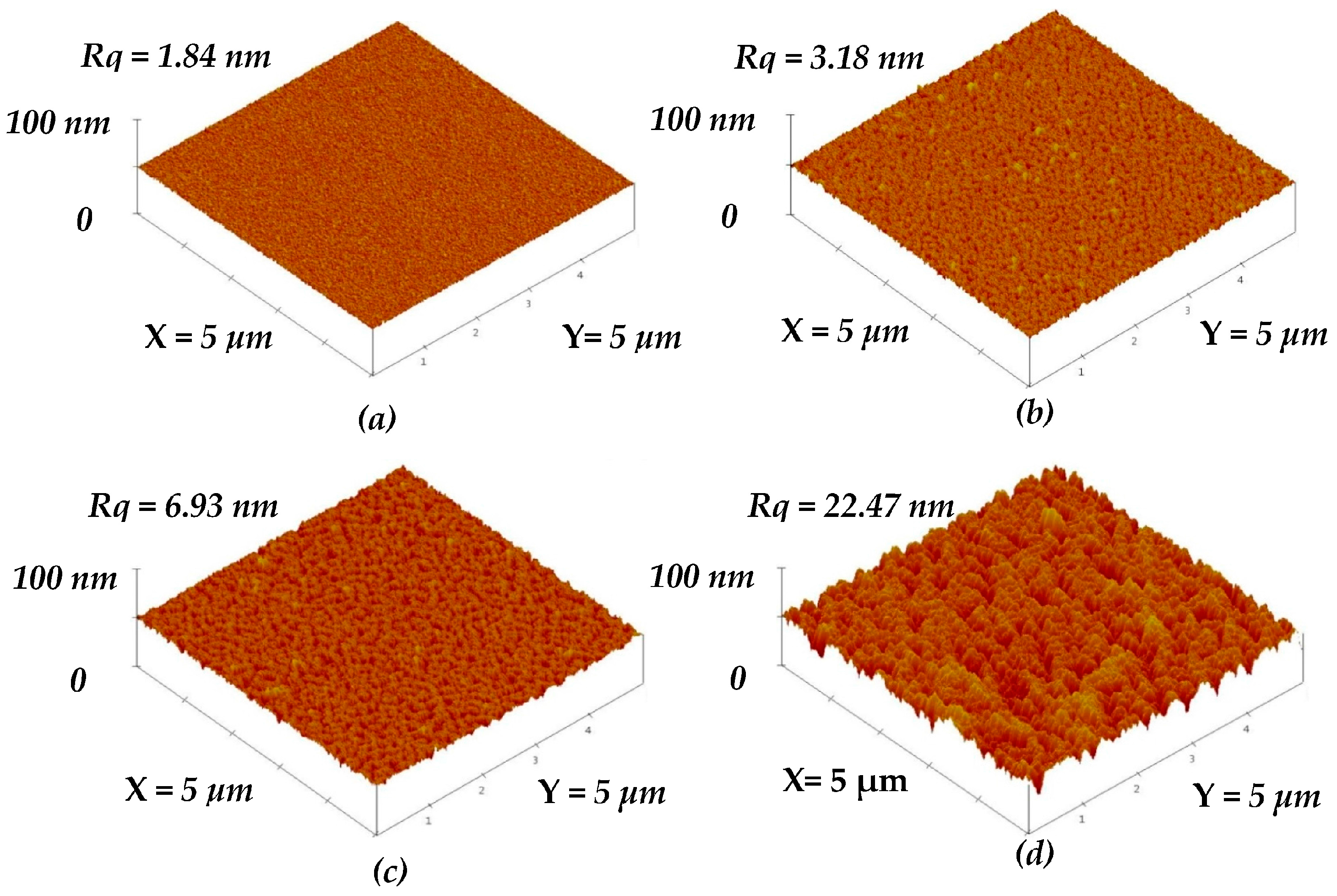
Figure 2b–d show the surface roughness of the a-TiOx film selectively etched by the HF solution for 10, 20, and 35 s, respectively (the un-treated a-TiOx film is given in Figure 2a for comparison). The untreated a-TiOx film exhibited a smooth surface with a roughness of about 1.84 nm, whereas an increase in the surface roughness was obtained from the a-TiOx films treated by the additive SFE process. The voids on the a-TiOx surface gradually became visible as the SFE-treated time increased. Notable pinnacles and valleys were then clearly observed from the surface of the a-TiOx film treated by the SFE process for 35 s, which corresponded to a very high surface roughness of 22.47 nm.
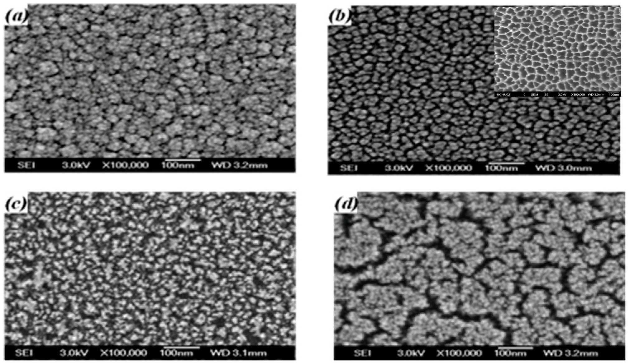
The surface morphologies of the untreated a-TiOx film and the films treated by the SFE process for 10, 20, and 35 s, respectively, are shown in Figure 3a–d. As shown in Figure 3a, the particles on the untreated a-TiOx surface are distributed densely and abnormally, whereas these particles observed from the a-TiOx film surface processed by the SFE treatment for 10 s became separated with a round-like shape. The SFE process also resulted in these particles being uniformly distributed with an average diameter of about 20 nm, which was similar to the porous size of the AAM mask, as shown in the inset figure. Fine particles were then observed from the a-TiOx film surface as it was further treated by the SFE process for 20 s (Figure 3b). The sidewall etching that led to the overcut profile was one possible reason why these particles appeared on the surface, evolving from a round-like to a needle-like shape. Meanwhile, the corresponding surface roughness of the a-TiOx film also increased from 3.18 to 6.93 nm, as measured from Figure 2c. When the SFE treatment on the a-TiOx film reached 35 s, the surface morphology also showed definite boundaries in addition to the fine particles. Referring to the etching thickness of the a-TiOx film given in Figure 1, the obvious and wide boundaries were attributed to the regions of the a-TiOx film that was completely removed from the substrate after etching by the HF solution without additive UV light irradiation.
These experiments demonstrated that the particles’ shape and distribution on the a-TiOx film surface were modifiable and controllable using the SFE treatment for different times. These base layers with surface nano-textures affecting the subsequent deposited a-TiOx film were then investigated. 
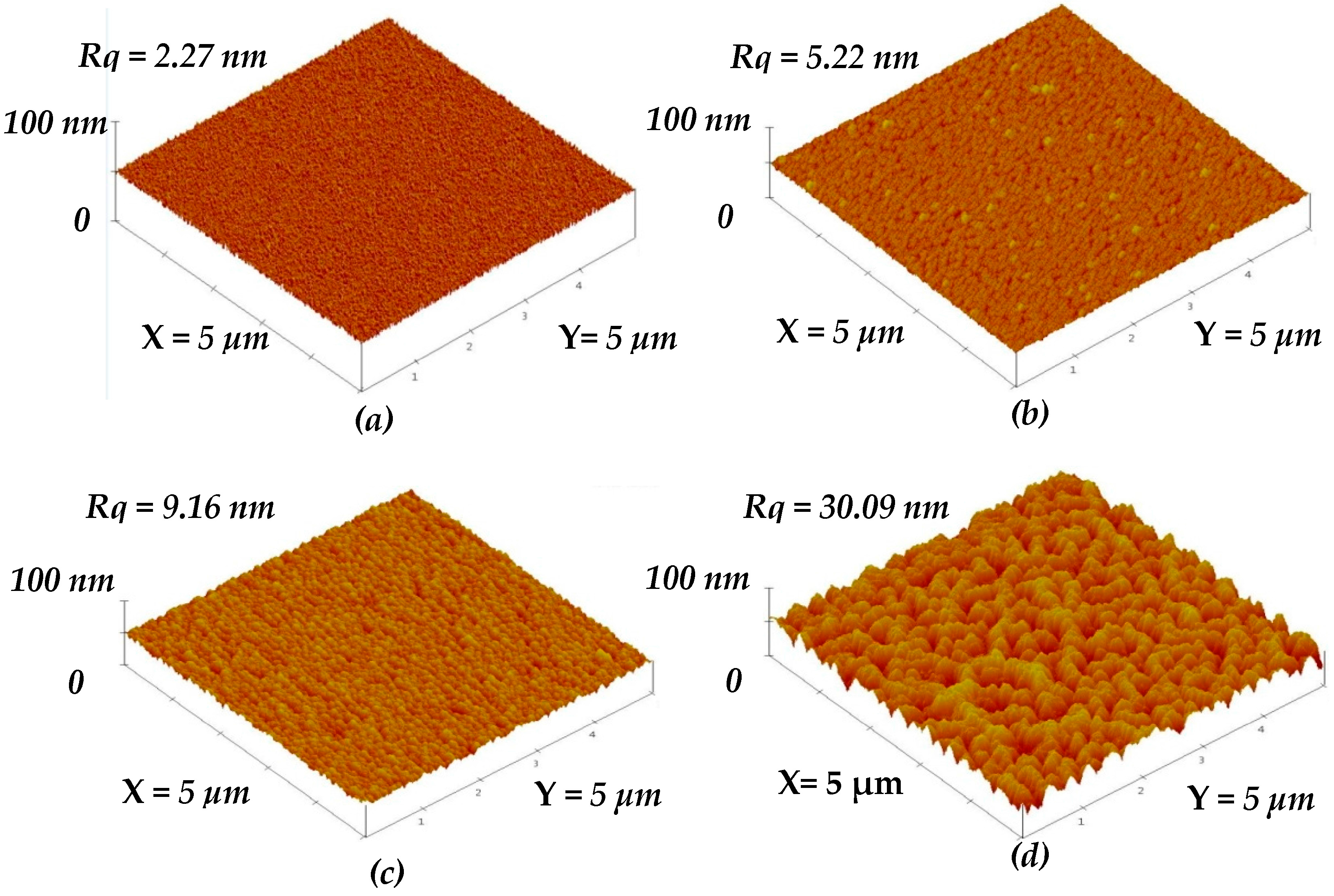
Figure 4b–d give the surface roughness of the a-TiOx films deposited onto the SFE-treated surface with nano-textures shown in Figure 2b–d, respectively, as well as the film deposited onto the untreated surface (Figure 4a). All the a-TiOx films prepared using this two-step deposition process exhibited a higher surface roughness than that of their base layers shown in Figure 2a–d. The surface roughness of the a-TiOx film deposited onto the untreated surface increased slightly to 2.27 nm. In contrast, a marked increase in the surface roughness was measured from the a-TiOx film deposited onto the SFE-treated surface. The rougher the surface of the base layer obtained, the higher the increase in the roughness of the subsequently deposited a-TiOx film. In addition, features of the pinnacles and valleys appearing on the surface of the a-TiOx film deposited onto the surface treated with SFE for 35 s (Figure 4d) became more visible compared to those observed from the surface of its base layer (Figure 2d).
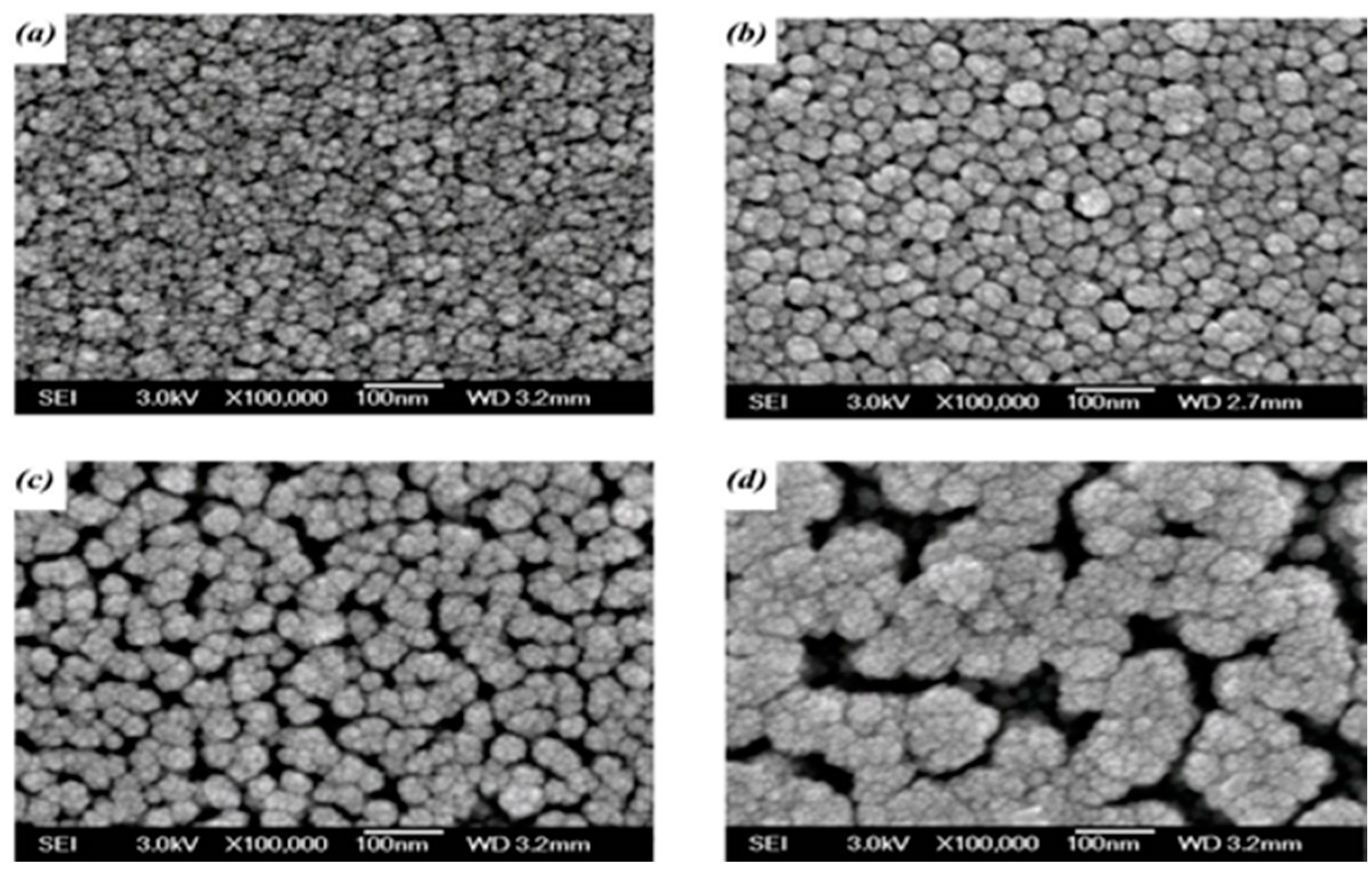
The corresponding surface morphologies shown in Figure 4 conducted from SEM measurements are presented in Figure 5a–d. The surface morphology of the a-TiOx film deposited onto the untreated surface (Figure 5a) was almost identical to the film deposited onto the substrate on which the particles were distributed randomly and densely as presented in Figure 3a. For the a-TiOx film deposited onto the surface with round-like particles, as shown in Figure 3b, the particles appearing on the a-TiOx film (Figure 5b) had an average diameter apparently larger than those distributed over the base layer’s surface, although their shape and distribution were quite similar. This suggested that the nuclei of the subsequently deposited a-TiOx film were prone to forming and growing along the particles distributed over the base layer. The growth of particles on the a-TiOx film became closer and resulted in the considerable increase in the surface roughness. For the a-TiOx film deposited onto the surface shown in Figure 3c, the nuclei growing along the needle-like structure resulted in the particles on the a-TiOx film surface evolving into a round-like shape with visible boundaries. As the surface morphologies of the two-step a-TiOx films were deeply relevant to the particles on the base layer, the distributions of the significant channels and clusters observed from the a-TiOx film shown in Figure 5d consisted of the growth of the fine particles and the enhancement of the boundaries appearing on the base layer shown in Figure 3d.
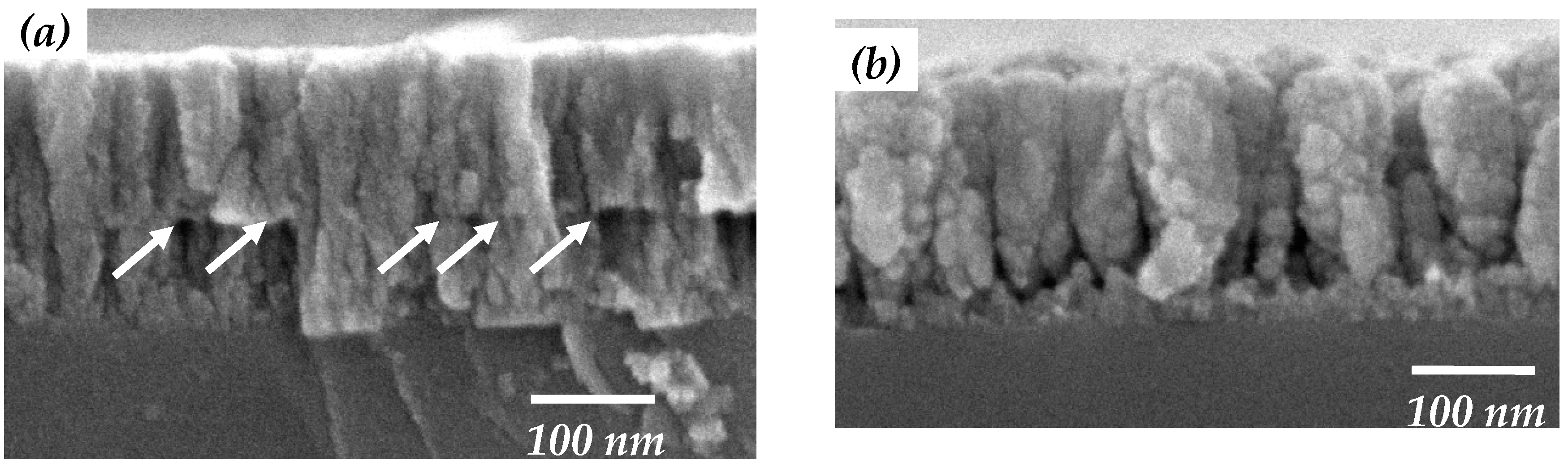
The cross-section micrographs shown in Figure 6a,b give further insights into the growth of the a-TiOx film prepared using the two-step deposition process. In Figure 6a, random and dense fiber-like structures can be seen in both a-TiOx layers, which had a definite interface, as indicated by arrows. This implied that the untreated base layer would not cause a structural change in the subsequently deposited a-TiOx film. In contrast, the cross-section of the two-step a-TiOx film shown in Figure 6b exhibited the feature of nanorod-like structures with no significant interface, confirming that the growth mechanism of the a-TiOx film deposited onto the SFE-treated base layer was completely different from the film deposited onto the untreated base layer. The dimension of these nanorod-like structures was found to be widened with the growth of the two-step a-TiOx film. Combined with their surface morphologies (Figure 3d and Figure 5d), the particles on the base layer achieved using the SFE treatment were likely to act as growth seeds for the subsequent a-TiOx deposition, thereby resulting in the upper a-TiOx film, demonstrating conformity in the base layer with the increase in the surface roughness.
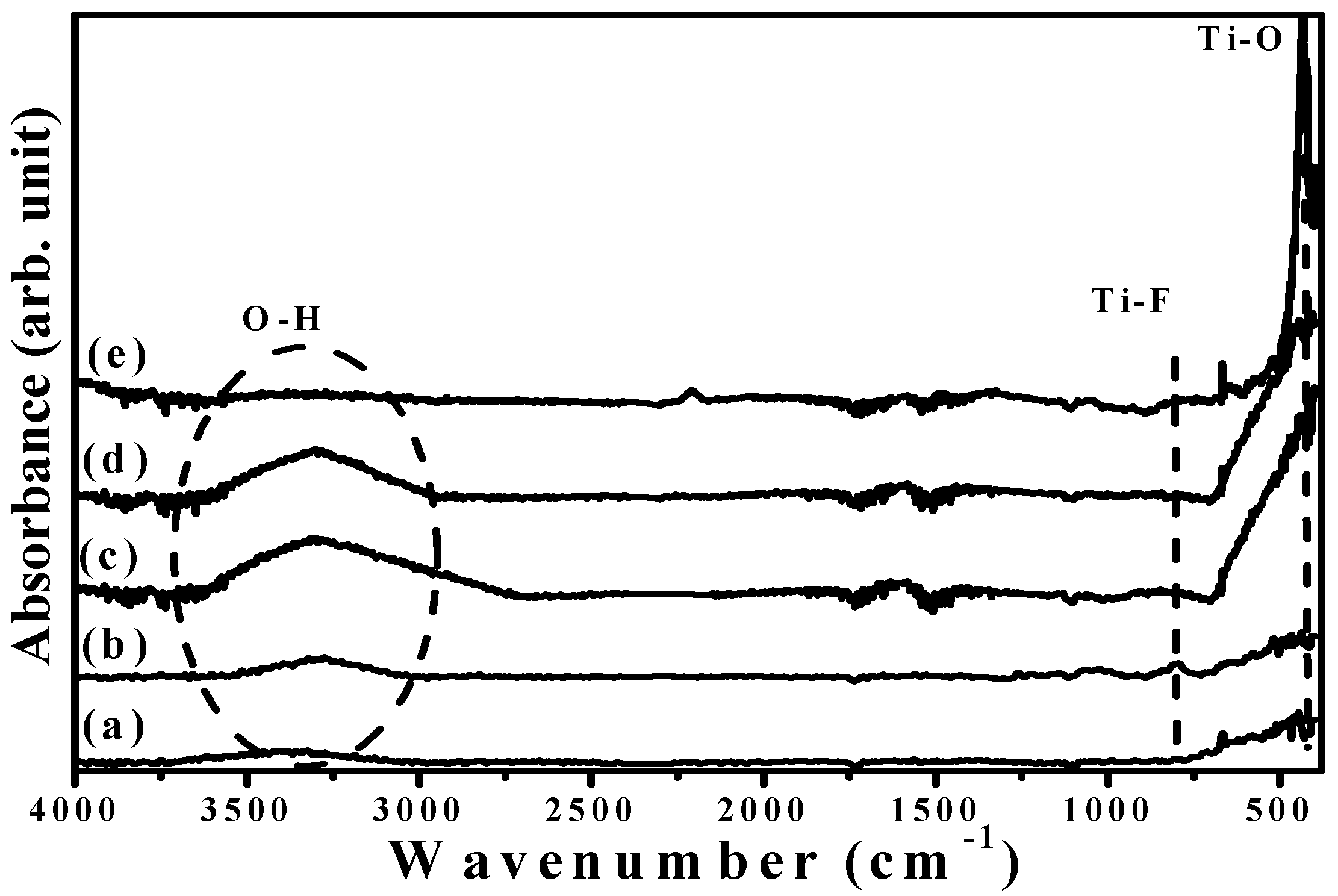
FTIR spectra of the base layer with and without an additive SFE treatment and the a-TiOx films prepared using two-step deposition are illustrated in Figure 7a–d, respectively (Figure 7e) also shows the FTIR spectrum of the annealed TiOx film for comparison). Both the untreated and SFE-treated base layers, as shown in Figure 7a,b, respectively, consisted of the fingerprint peak of the Ti–O bond around 400–800 cm−1 with the functional group of hydroxyl (OH) around high wavenumbers (2800–3700 cm−1) [12]. The SFE treatment also caused the base layer to emit an additive signal at about 820 cm−1, which was associated with the Ti–F vibration mode [13]. In addition, the incorporation of the fluorine ions into the base layer led to a shift of the O-H bond from 3450 to 3275 cm−1 due to an increase in the surface acidity. When the a-TiOx film was deposited onto the SFE-treated base layer, the Ti–F bond was hardly observed in the FTIR spectrum (Figure 7d). Compared with the FTIR spectrum of the a-TiOx film deposited onto the untreated base layer (curve c), both spectra only featured Ti–O and O–H bonds with almost the same peak position, except for a higher relative O-H bond intensity obtained from the a-TiOx film deposited onto the SFE-treated base layer. Since the porous structures distributed in the low-temperature deposited oxidation film were the main reason responsible for the formation of the O–H groups [15,16], the reinforcement in the O–H bond obtained from the two-step deposition of the a-TiOx coated onto the SFE-treated base layer thus implied the increase in the amounts of the pores. In addition, a sharp and intense Ti–O bond with the disappearance of the O–H bond as a consequence of the anatase crystallization was obtained from the FTIR spectrum of the annealed TiOx film.
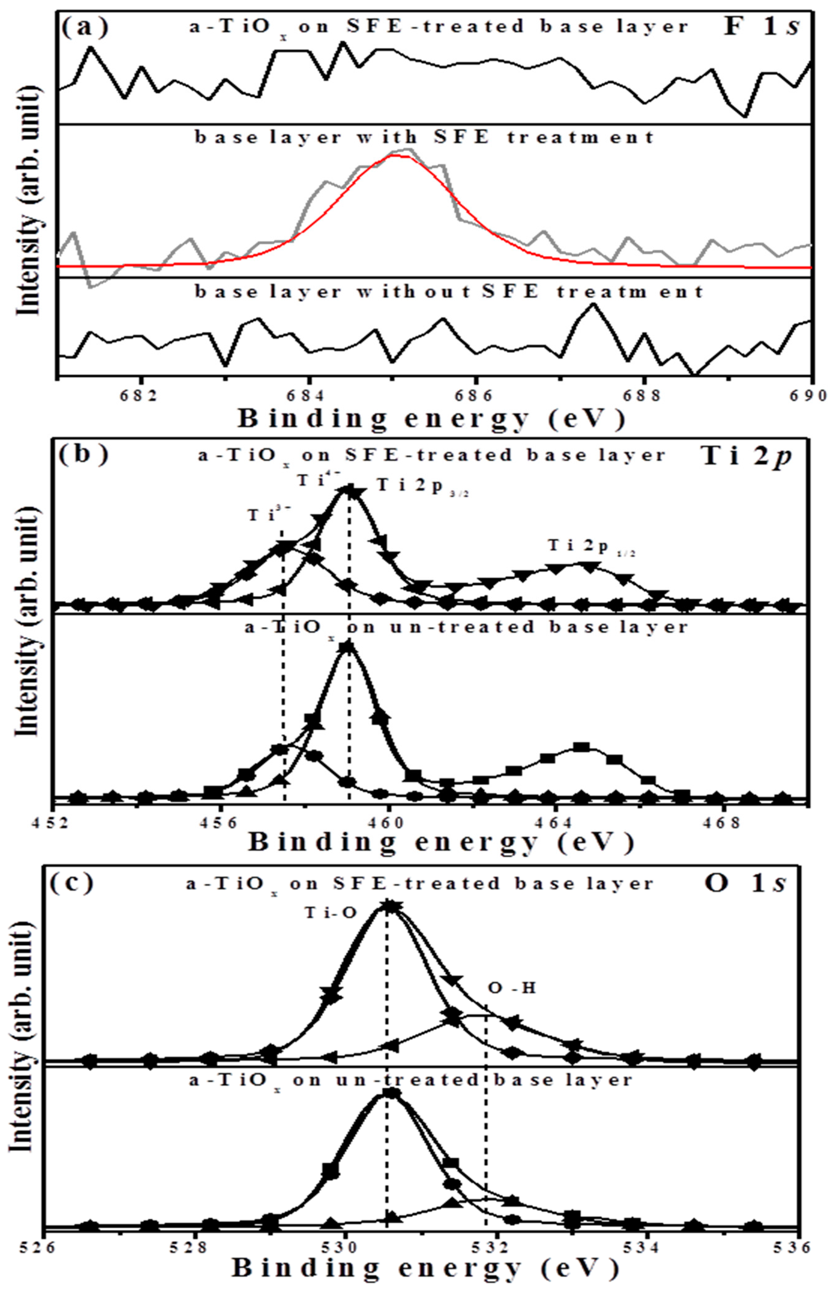
The binding energies related to the F 1s, Ti 2p, and O 1s core levels measured from the surface of the two-step deposited a-TiOx film as well as the base layer are respectively illustrated in Figure 8a–c. Although a significant fluorine signal on the surface of the base layer emerged at about 684.9 eV, which was assigned to the Ti–F chemical bond due to the SFE treatment [17], this signal was absent in the surface of the subsequently deposited a-TiOx film, indicating the achievement of the fluorine-free surface. In the Ti 2p spectrum (Figure 8b), both the peaks of the binding energies for the Ti 2p1/2 and Ti 2p3/2 occurred at approximately 464.6 and 458.9 eV, respectively, with a binding energy difference of 5.7 eV. A broad signal with a distinct satellite peak was observed from the binding energy of Ti 2p3/2 for the a-TiOx film deposited onto the SFE-treated base layer, while this peak became sharp with a tail extending to the low binding energy in the spectrum of the a-TiOx film deposited onto the untreated base layer. The peak of Ti 2p3/2 could be deconvoluted into two species of Ti4+ and Ti3+ ion states at 457.6 and 459.0 eV, respectively [18]. The composition of the Ti3+ to Ti4+ state (in the area of Ti3+/(Ti4+ + Ti3+)), which was associated with the deficiency in the oxygen atoms on the surface, apparently increased from 0.29 to 0.39 as the a-TiOx film was deposited onto the SFE-treated base layer. Regarding the O 1s spectra (Figure 8c), both surfaces of these two samples displayed an intense peak with a long tail extending to a high binding energy that could be deconvoluted into two feature peaks. The binding energy peak located at 530.6 eV was related to the Ti–O chemical bond, where the peak at the high binding energy of 531.8 eV emerged from the hydroxyl group (O–H) [19,20]. As determined from previous papers [21,22], the presence of the O-H bond indicated the termination of the chemical bond and/or contaminants and, thus, was responsible for the structural voids and boundaries. Accordingly, marked boundaries and voids observed from the surface and cross-section morphologies of the a-TiOx film deposited onto the SFE-treated base layer were hydroxylated more intensely in the binding energy of O 1s (approximately 0.31, in the area of O–H/(Ti–O + O–H)) than those of the film deposited onto the untreated base layer (approximately 0.24).
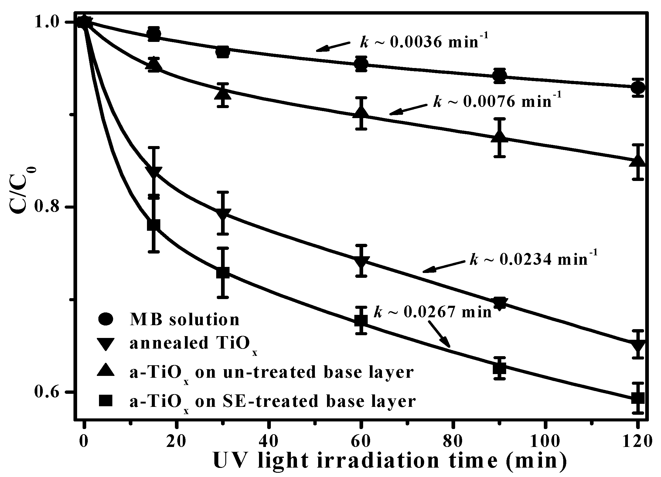
In addition, because the hydroxyl groups are beneficial for trapping hole carriers to suppress the recombination of the photo-generated electron-hole pairs, as demonstrated in previous studies [23,24], the a-TiOx film deposited onto the SFE-treated base layer to degrade the MB solution, as depicted in Figure 9, is greatly improved compared to the same film deposited onto the untreated base layer. It is also worth noting that the a-TiOx film with a surface free of the fluorine ions achieved using the two-step deposition even exhibited better efficiency in decomposing the MB solution than the annealed TiOx film with anatase structures. The rate constant, k, which represents the quality of the photocatalytic activity of the film can be evaluated by fitting the curves shown in Figure 9, using the following relationship [25]:
ln ( C / C 0 ) = k t
where C and C0 are the concentrations of the MB solution at a UV light irradiation time of t = 0 and t, respectively. The k value evaluated from each curve is denoted in Figure 9. Clearly, the a-TiOx film deposited onto the SFE-treated base layer corresponded to a rate constant of 0.0267 min−1, which was three times higher than the film deposited onto the untreated base layer (0.0076 min−1) as well as a little higher than that of the annealed TiOx film (0.0234 min−1). According to the investigations into the morphologies and the analysis of the chemical bond configurations of the two-step deposited a-TiOx film, the apparent roughening and nano-textured surface of the upper a-TiOx film without the incorporation of the fluorine ions that grew by conforming along the particle seeds on the base layer surface, which was achieved using an additive SFE treatment, was the mechanism responsible for the great enhancement in the resulting photocatalytic activity.

4. Conclusions

The depth-dependent morphology of the surface-fluorinated a-TiOx film was realized using an additive SFE treatment for different times. At the initial stage, the size and shape of these particles distributed over the a-TiOx film surface after treatment with the SFE process for 10 s conformed to the patterns of the shadow mask. As the SFE treatment increased to 20 s, the shape of the particles appearing on the a-TiOx film surface evolved from a round-like to a needle-like shape as a consequence of the apparent sidewall etching effect. Eventually, significant channels that corresponded to the film being completely removed from the substrate were observed from the a-TiOx film processed by an additive SFE treatment for 35 s. The fluorinated surface with specific nano-textures of the a-TiOx film acted as seed layer for the subsequently deposited a-TiOx film according to the investigations of the surface and cross-section morphologies of the resulting a-TiOx film. The nuclei of the a-TiOx film self-assembled on the particles distributed over the SFE-treated base layer and then grew up to cause an apparent increase in surface roughness. Such roughening of the surface without the fluorine ion incorporation was achieved using the two-step deposition due to the deposition being selective, which also resulted in the film surface being abundant in the hydroxyl groups that were helpful for suppressing the recombination of the photo-generated electron-hole pairs. Accordingly, the fluorine-free a-TiOx film deposited onto the SFE-treated base layer which had a nanorod-like structure possessing efficient photocatalytic activity, with a rate constant of 0.0267 min−1; this was much higher than that of the film deposited on the untreated base layer (~0.0076 min−1 ), as evaluated from these films photo-degrading in the MB solution.

Acknowledgments

This work was supported by the National Science Council and Industrial Technology Research Institute (ITRI South) under No. A200-105BA2 and the Ministry of Science and Technology under 105-2622-E-150-004-CC2.

Author Contributions

Day-Shan Liu organized and designed the experiment procedures; Tai-Hong Chen and Chun-Hao Chang wrote the paper; Pei-Yu Li and Hua-Wen Liu executed the film deposition; Yi-Shan Lu performed the thin film measurements and analysis. All authors read and approved the final version of the manuscript to be submitted.

Conflicts of Interest

The authors declare no conflict of interest.

References

  1. Khan, S.U.M.; Al-Shahry, M.; Ingler, W.B., Jr. Efficient photochemical water splitting by a chemically modified n-TiO2. Science 2002, 297, 2243–2245. [Google Scholar] [CrossRef] [PubMed]
  2. Liu, D.S.; Lin, T.W.; Huang, B.W.; Juang, F.S.; Lei, P.H.; Hu, C.Z. Light-extraction enhancement in GaN-based light-emitting diodes using grade-refractive-index amorphous titanium oxide films with porous structures. Appl. Phys. Let. 2009, 94, 143502. [Google Scholar] [CrossRef]
  3. Necula, B.S.; Fratila-Apachitei, L.E.; Zaat, S.A.J.; Apachitei, L.; Duszczyk, J. In vitro antibacterial activity of porous TiO2–Ag composite layers against methicillin-resistant Staphylococcus aureus. Acta Biomater. 2009, 5, 3573–3580. [Google Scholar] [CrossRef] [PubMed]
  4. Fang, Y.; Wang, X.; Ai, X.; Huang, J.; Wang, Q.; Wu, T. Sputtered TiOx thin film as compact layer for solid-state dye sensitized solar cells. Ceram. Int. 2014, 40, 15941–15949. [Google Scholar] [CrossRef]
  5. Kmetykó, Á.; Mogyorós, K.; Gerse, V.; Kónya, Z.; Pusztai, P.; Dombi, A.; Hernádi, K. Photocatalytic H2 production using Pt-TiO2 in the presence of oxalic acid: Influence of the noble metal size and the carrier gas flow rat. Materials 2014, 7, 7022–7038. [Google Scholar] [CrossRef]
  6. Eufinger, K.; Poelman, D.; Poelman, H.; De Gryse, R.; Marin, G.B. Photocatalytic activity of dc magnetron sputter deposited amorphous TiO2 thin films. Appl. Surf. Sci. 2007, 254, 148–152. [Google Scholar] [CrossRef]
  7. Tian, G.; Fu, H.; Jing, L.; Tian, C. Synthesis and photocatalytic activity of stable nanocrystalline TiO2 with high crystallinity and large surface area. J. Hazard. Mater. 2009, 161, 1122–1130. [Google Scholar] [CrossRef] [PubMed]
  8. Su, Y.; Chen, S.; Quan, X.; Zhao, H.; Zhang, Y. A silicon-doped TiO2 nanotube arrays electrode with enhanced photoelectrocatalytic activity. Appl. Surf. Sci. 2008, 255, 2167–2172. [Google Scholar] [CrossRef]
  9. Wu, C.Y.; Hong, S.C.; Hwang, F.T.; Lai, L.W.; Lin, T.W.; Liu, D.S. Effect of nickel oxide seed layers on the annealed-amorphous titanium oxide thin films prepared using plasma-enhanced chemical vapor deposition. Thin Solid Films 2011, 520, 320–327. [Google Scholar] [CrossRef]
  10. Chen, J.Z.; Chen, T.H.; Lai, L.W.; Li, P.Y.; Liu, H.W.; Hong, Y.Y.; Liu, D.S. Preparation and characterization of the surface photocatalytic activity with NiO/TiO2 nanocomposite structure. Materials 2015, 8, 4273–4286. [Google Scholar] [CrossRef]
  11. Hatanaka, Y.; Naito, H.; Kando, M. Photocatalytic characteristics of hydro-oxygenated amorphous titanium oxide films prepared using remote plasma enhanced chemical vapor deposition. Appl. Surf. Sci. 2005, 244, 554–557. [Google Scholar] [CrossRef]
  12. Wu, C.Y.; Chiang, B.S.; Chang, S.; Liu, D.S. Determination of photocatalytic activity in amorphous and crystalline titanium oxide films prepared using plasma-enhanced chemical vapor deposition. Appl. Surf. Sci. 2011, 257, 1893–1897. [Google Scholar] [CrossRef]
  13. Shih, P.C.; Huang, C.H.; Chen, T.H.; Lai, L.W.; Lu, Y.S.; Liu, D.S. Enhancement on Photocatalytic Activity of an Amorphous Titanium Oxide Film with Nano-Textured Surface by Selective-Fluorination Etching Process. Mater. Res. Bull. 2014, 52, 177–182. [Google Scholar] [CrossRef]
  14. Chen, J.Z.; Chen, T.H.; Lai, L.W.; Huang, C.H.; Hong, S.C.; Liu, D.S. A quality photocatalytic activity of an amorphous titanium oxide film achieved using the selectively photochemical etching and its application for the organic light emitting diode encapsulation. Microelectron. Eng. 2015, 148, 5–9. [Google Scholar] [CrossRef]
  15. Teshima, K.; Sugimura, H.; Inoue, Y.; Takai, O. Gas Barrier Performance of Surface-Modified Silica Films with Grafted Organosilane Molecules. Langmuir 2003, 19, 8331–8334. [Google Scholar] [CrossRef]
  16. Yang, L.L.; Lai, Y.S.; Chen, J.S.; Tsai, P.H.; Chen, C.L.; Jason Chang, C. Compositional tailored sol-gel SiO2–TiO2 thin films: Crystallization, chemical bonding configuration, and optical properties. J. Mater. Res. 2005, 20, 3141–3149. [Google Scholar] [CrossRef]
  17. Yu, J.; Wang, W.; Cheng, B.; Su, B.L. Enhancement of photocatalytic activity of mesporous TiO2 powders by hydrothermal surface fluorination treatment. J. Phys. Chem. C 2009, 113, 6743–6750. [Google Scholar] [CrossRef]
  18. Lin, X.; Rong, F.; Fu, D.; Yuan, C. Enhanced photocatalytic activity of fluorine doped TiO2 by loaded with Ag for degradation of organic pollutants. Powder Technol. 2012, 219, 173–178. [Google Scholar] [CrossRef]
  19. Domaradzki, J.; Kaczmarek, D.; Prociow, E.L.; Borkowska, A.; Schmeisser, D.; Beuckert, G. Microstructure and optical properties of TiO2 thin films prepared by low pressure hot target reactive magnetron sputtering. Thin Solid Films 2006, 513, 269–274. [Google Scholar] [CrossRef]
  20. Chen, S.; Zhang, S.; Wei, L.; Wei, Z. Preparation and activity evaluation of p-n junction photocatalyst NiO/TiO2. J. Hazard. Mater. 2008, 155, 320–326. [Google Scholar]
  21. Schuisky, M.; Kukli, K.; Aarik, J.; Lu, J.; Hårsta, A. Epitaxial growth of TiO2 films in a hydroxyl-free atomic layer deposition. J. Crystal Growth 2002, 235, 293–299. [Google Scholar] [CrossRef]
  22. Kumar, N.; Kozakov, A.T.; Dash, S.; Tyagi, A.K.; Lin, I.N. Microstructure, chemical bonds, and friction properties of nanocrystalline diamond films deposited in two different plasma media. Phys. Solid State 2013, 55, 2076–2087. [Google Scholar] [CrossRef]
  23. Nakamura, M.; Kobayashi, M.; Kuzuya, N.; Komatsu, T.; Mochizuka, T. Hydrophilic property of SiO2/TiO2 double layer films. Thin Solid Films 2006, 502, 121–124. [Google Scholar] [CrossRef]
  24. Xin, B.; Wang, P.; Ding, D.; Liu, J.; Ren, Z.; Fu, H. Effect of surface species on Cu-TiO2 photocatalytic activity. Appl. Surf. Sci. 2008, 254, 2569–2574. [Google Scholar] [CrossRef]
  25. Li, H.; Zhao, G.; Han, G.; Song, B. Hydrophilicity and photocatalysis of Ti1xVxO2 films prepared by sol–gel method. Surf. Coat. Technol. 2007, 201, 7615–7618. [Google Scholar] [CrossRef]
Figure 1. Etching thickness of the a-TiOx film with and without the UV light pre-irradiation and then immersed in the HF etching solution for different etching times.
Materials 09 00429 g001
Figure 2. Surface roughness of the (a) un-treated a-TiOx film; and SFE-treated a-TiOx film for (b) 10; (c) 20; and (d) 35 s; respectively.
Materials 09 00429 g002
Figure 3. Surface morphologies of the (a) untreated a-TiOx film; and SFE-treated a-TiOx film for (b) 10; (c) 20; and (d) 35 s, respectively (the AAM patterns is provided in inset figure of Figure 3b).
Materials 09 00429 g003
Figure 4. Surface roughness of the a-TiOx film deposited onto (a) untreated base layer; and SFE-treated base layers for (b) 10; (c) 20; and (d) 35 s; respectively.
Materials 09 00429 g004
Figure 5. Surface morphologies of the a-TiOx film deposited onto (a) untreated base layer; and SFE-treated base layers for (b) 10; (c) 20; and (d) 35 s; respectively.
Materials 09 00429 g005
Figure 6. Cross-section images of the a-TiOx film deposited onto (a) untreated; and (b) SFE-treated base layers (the arrows in Figure 6a mark the interface of the two-step deposited a-TiOx film).
Materials 09 00429 g006
Figure 7. FTIR spectra of the (a) untreated; and (b) SFE-treated base layers and the a-TiOx films deposited onto the (c) untreated; and (d) SFE-treated base layers; as well as (e) the annealed TiOx film.
Materials 09 00429 g007
Figure 8. Binding energies related to the (a) F 1s core of the untreated and SFE-treated base layers as well as that of the a-TiOx deposited onto the SFE-treated based layer; (b) Ti 2p; and (c) O 1s core levels of the a-TiOx film deposited onto the untreated and SFE-treated base layers.
Materials 09 00429 g008
Figure 9. Photo-degradation to MB solution using a-TiOx films deposited onto untreated and SFE-treated base layers as well as using the annealed TiOx film (MB solution decomposed by the UV light irradiation also is shown for comparison).
Materials 09 00429 g009

