
Physical Simulation and Numerical Simulation of Flash Butt Welding for Innovative Dual Phase Steel DP590: A Comparative Study
 ,
,
Abstract
:1. Introduction
2. Experiments and Simulations
2.1. Experimental Procedure
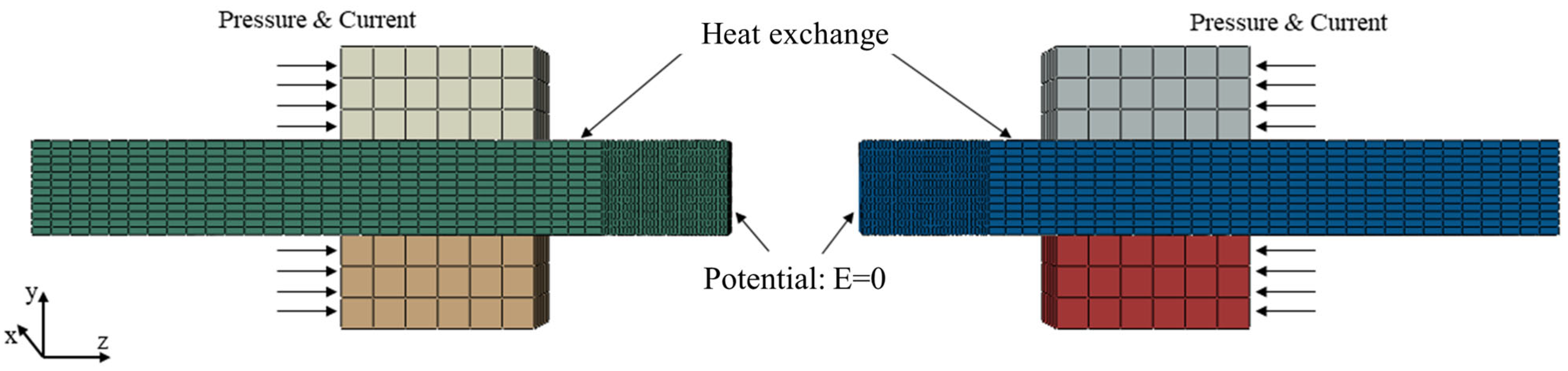
2.2. FEM Simulation

| DP590 | ||||||||
|---|---|---|---|---|---|---|---|---|
| Temperature (°C) | 25 | 100 | 200 | 300 | 400 | - | - | - |
| Thermal conductivity (W/(m∙k)) | 65.3 | 54.9 | 45.2 | 36.2 | 28.5 | - | - | - |
| Temperature (°C) | 100 | 200 | 300 | 400 | 500 | 600 | 700 | 800 |
| Coefficient of thermal expansion (×10−6K−1) | 12.76 | 13.66 | 14.27 | 15.17 | 15.52 | 15.64 | 15.41 | 12.73 |
| Temperature (°C) | 25 | 50 | 100 | 150 | 200 | 300 | 400 | 450 |
| Specific heat capacity (J/kg∙°C) | 460 | 468 | 485 | 502 | 519 | 552 | 586 | 602 |
| Temperature (°C) | 20 | 25 | 100 | 200 | 300 | 400 | 500 | 600 |
| Electrical resistivity (×10−6Ω∙m) | 0.284 | 0.301 | 0.335 | 0.402 | 0.478 | 0.564 | 0.666 | 0.806 |
3. Results
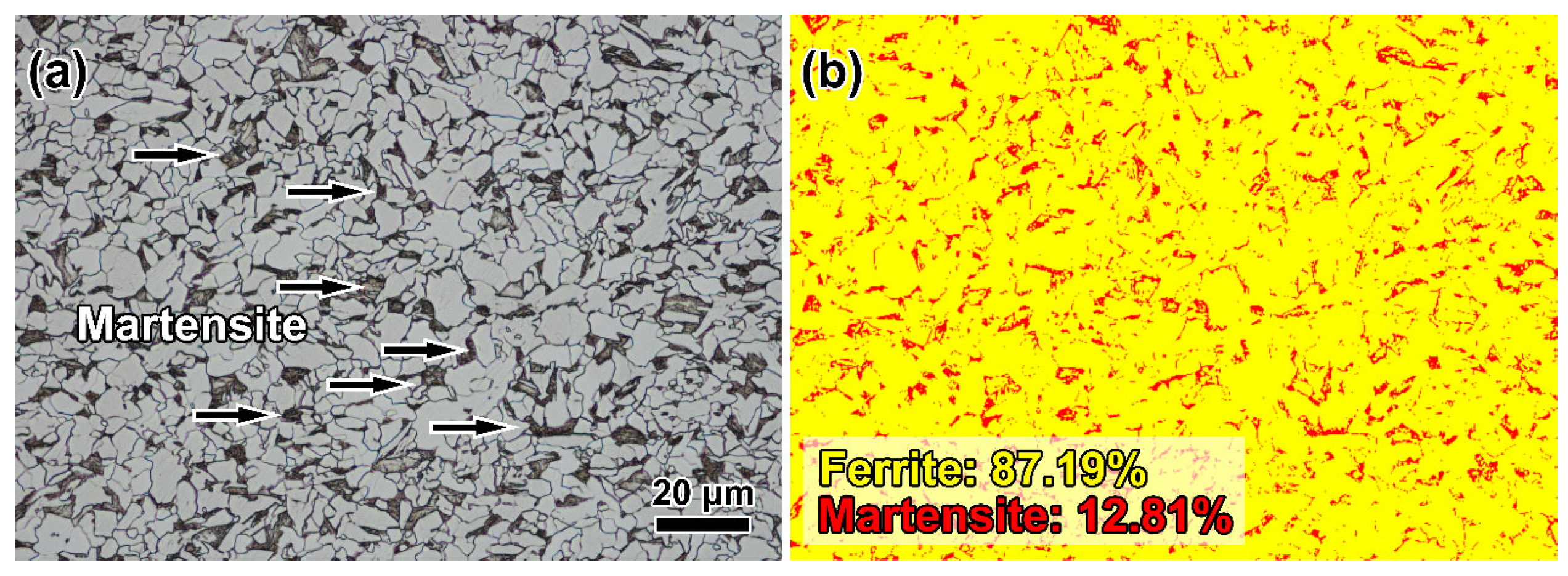
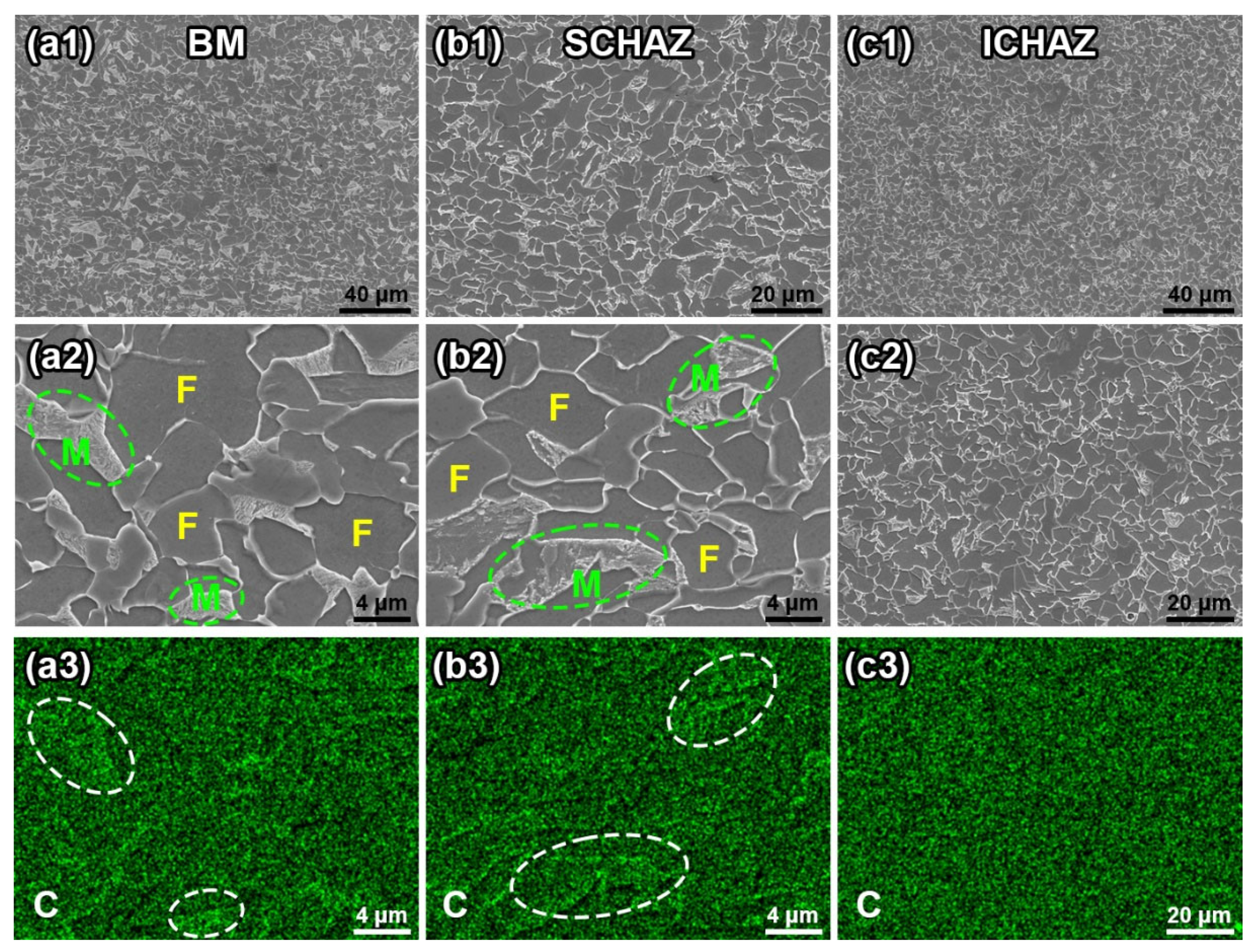
3.1. Microstructure
3.2. Mechanical Properties
3.3. Thermal Behaviour
4. Discussions
5. Conclusions
- (1)
- The DP590 processed by the flash butt welding mainly had four types of HAZs. The CGAHZ and FGHAZ mainly contain lamellar martensite structures. The ICHAZ has fine ferrite grains and tempered martensite structures due to incomplete phase transition. The SCHAZ mainly has ferrite grains and island martensite structures, which is similar to the BM.
- (2)
- The CGHAZ has the highest hardness due to its lamellar martensite structures and large prior austenite grains. The lamellar martensite and fine grains provide a high hardness (higher than the BM) for the FGHAZ and ICHAZ, respectively. The softening behaviour appeared in the SCHAZ, whose hardness decreased by 9.2% compared with the BM. The ultimate tensile strength of the FBW-ed sample decreased by 9.1%.
- (3)
- The high heat input resulted in the diffusion of carbon elements during the flash butt welding process, and the carbon diffusion led to the tempering and decomposition of martensite islands in the SCHAZ. The microstructure and grain size of the SCHAZ is similar to the BM, i.e., ferrite + martensite, but the tempering and decomposition of martensite islands led to softening behaviour.
Supplementary Materials
Author Contributions
Funding
Institutional Review Board Statement
Informed Consent Statement
Data Availability Statement
Conflicts of Interest
References
- Xu, Z.; Lu, P.; Shu, Y. Microstructure and fracture mechanism of a flash butt welded 380CL steel. Eng. Fail. Anal. 2016, 62, 199–207. [Google Scholar] [CrossRef]
- Banerjee, A.; Ntovas, M.; Da Silva, L.; Rahimi, S. Effect of rotational speed and inertia on the mechanical properties and microstructural evolution during inertia friction welding of 8630M steel. Mater. Lett. 2021, 296, 129906. [Google Scholar] [CrossRef]
- Wang, J.; Ma, C.; Han, J.; Jiang, Z.; Linton, V. Acquisition of HSLA steel weld joints with excellent mechanical performance through flash butt welding physical simulation. Mater. Lett. 2021, 303, 130511. [Google Scholar] [CrossRef]
- Jha, G.; Das, S.; Lodh, A.; Haldar, A. Development of hot rolled steel sheet with 600 MPa UTS for automotive wheel application. Mater. Sci. Eng. A 2012, 552, 457–463. [Google Scholar] [CrossRef]
- Xi, C.Y.; Sun, D.Q.; Xuan, Z.Z.; Wang, J.G.; Song, G.S. The effects of flash allowance and upset allowance on microstructures and mechanical properties of flash butt welded RS590CL steel joints. J. Mater. Res. 2016, 31, 3968–3980. [Google Scholar] [CrossRef]
- Çetinkaya, C.; Arabaci, U. Flash butt welding application on 16MnCr5 chain steel and investigations of mechanical properties. Mater. Des. 2006, 27, 1187–1195. [Google Scholar] [CrossRef]
- Zhang, F.; Lv, B.; Hu, B.; Li, Y. Flash butt welding of high manganese steel crossing and carbon steel rail. Mater. Sci. Eng. A 2007, 454–455, 288–292. [Google Scholar] [CrossRef]
- Bauri, L.F.; Alves, L.H.D.; Pereira, H.B.; Tschiptschin, A.P.; Goldenstein, H. The role of welding parameters on the control of the microstructure and mechanical properties of rails welded using FBW. J. Mater. Res. Technol. 2020, 9, 8058–8073. [Google Scholar] [CrossRef]
- Li, X.; Ma, R.; Liu, X.; Lv, Q.; Wang, X.; Tian, Z. Effect of laser shock peening on fatigue properties of U75VG rail flash-butt welding joints. Opt. Laser Technol. 2022, 149, 107889. [Google Scholar] [CrossRef]
- Zhang, J.; Zhang, X.; Li, D.; Lv, Q.; Ma, R. Extrusion behavior of impurities in upsetting process of rail flash butt welding based on finite element method. J. Market. Res. 2019, 34, 3351–3360. [Google Scholar] [CrossRef]
- Kuroda, T.; Ikeuchi, K.; Ikeda, H. Flash butt resistance welding for duplex stainless steels. Vacuum 2006, 80, 1331–1335. [Google Scholar] [CrossRef]
- Xi, C.; Sun, D.; Xuan, Z.; Wang, J.; Song, G. Microstructures and mechanical properties of flash butt welded high strength steel joints. Mater. Des. 2016, 96, 506–514. [Google Scholar] [CrossRef]
- Xi, C.; Sun, D.; Xuan, Z.; Wang, J.; Song, G. Microstructure evolution and mechanical properties of flash butt-welded Inconel718 joints. Mater. Sci. Eng. A 2018, 718, 34–42. [Google Scholar]
- Lu, P.; Xu, Z.; Jiang, K.; Ma, F.; Shu, Y. Influence of flash butt welding parameters on microstructure and mechanical properties of HSLA 590CL welded joints in wheel rims. J. Market. Res. 2017, 32, 831–842. [Google Scholar] [CrossRef]
- Lu, P.; Xu, Z.; Shu, Y.; Ma, F. Microstructure and failure analysis of flash butt welded HSLA 590CL steel joints in wheel rims. JOM 2017, 69, 135–143. [Google Scholar] [CrossRef]
- Wang, W.; Shi, Y.; Lei, W.; Tian, Z.T. Study on the flash butt welding of 400 MPa ultra-fine grain steel. J. Mater. Eng. Perform. 2003, 12, 581–583. [Google Scholar]
- Shajan, N.; Arora, K.S.; Asati, B.; Sharma, V.; Shome, M. Effects of post-weld heat treatment on the microstructure and toughness of flash butt welded high-strength low-alloy steel. Metall. Mater. Trans. A 2018, 49, 1276–1286. [Google Scholar] [CrossRef]
- Wang, X.; Liu, X.; Zhang, J.; Deng, J.; Lv, Q. Numerical simulation of end face heating in alternating current flash butt welding based on electrical–thermal bidirectional coupling. Int. J. Adv. Manuf. Technol. 2022, 120, 173–183. [Google Scholar] [CrossRef]
- Wang, J.; Lu, Y.; Han, J.; Qi, J.; Sun, L.; Jiang, Z.; Ma, C.; Linton, V. Study on microstructure evolution and mechanical properties of high-strength low-alloy steel welds realized by flash butt welding thermomechanical simulation. Int. J. Adv. Manuf. Technol. 2022, 122, 639–658. [Google Scholar] [CrossRef]
- Qiu, L.; Tang, J.M.; Liu, H.G. Constitutive relationship and hot processing pattern of high-strength steel DP590 based on hot tensile test. Forg. Stamp. Technol. 2017, 42, 121–125. (In Chinese) [Google Scholar]
- Yu, B.D.; Song, W.D.; Zhang, F.C. sNumerical simulation of temperature field on flash butt welding for high manganese steels. Acta Metall. Sin. Engl. 2005, 18, 547–551. [Google Scholar]
- Wang, W.; Shi, Y.; Lei, Y.; Tian, Z. FEM simulation on microstructure of DC flash butt welding for an ultra-fine grain steel. J. Mater. Process. Technol. 2005, 161, 497–503. [Google Scholar] [CrossRef]
- Wang, M.; Zhang, H.-T.; Pan, H.; Lei, M. Numerical simulation of nugget formation in resistance spot welding of DP590 dual-phase steel. J. Shanghai Jiao Tong Univ. 2009, 43, 56–60. (In Chinese) [Google Scholar]
- Krauss, G. Tempering of lath martensite in low and medium carbon steels: Assessment and challenges. Steel Res. Int. 2017, 88, 1700038. [Google Scholar] [CrossRef]
- Ostash, O.P.; Kulyk, V.V.; Poznyakov, V.D.; Haivorons’kyi, O.A.; Markashova, L.I.; Vira, V.V.; Duriagina, Z.A.; Tepla, T.L. Fatigue crack growth resistance of welded joints simulating the weld-repaired railway wheels metal. Arch. Mater. Sci. Eng. 2017, 86, 49–52. [Google Scholar] [CrossRef]


| Elements | C | Mn | Cr | Si | Al | Ti | Nb | P | N | S | Fe |
|---|---|---|---|---|---|---|---|---|---|---|---|
| Wt. % | 0.056 | 1.199 | 0.268 | 0.085 | 0.039 | 0.02 | 0.013 | 0.015 | 0.004 | 0.001 | Bal. |
| Electrode Voltage (V) | Contact Interaction Potential (V) | Step Time (s) | Initial Temperature (°C) |
|---|---|---|---|
| 220 | 0 | 1.2 | 20 |
Disclaimer/Publisher’s Note: The statements, opinions and data contained in all publications are solely those of the individual author(s) and contributor(s) and not of MDPI and/or the editor(s). MDPI and/or the editor(s) disclaim responsibility for any injury to people or property resulting from any ideas, methods, instructions or products referred to in the content. |
© 2023 by the authors. Licensee MDPI, Basel, Switzerland. This article is an open access article distributed under the terms and conditions of the Creative Commons Attribution (CC BY) license (https://creativecommons.org/licenses/by/4.0/).
Share and Cite
Song, J.; Zhu, L.; Wang, J.; Lu, Y.; Ma, C.; Han, J.; Jiang, Z. Physical Simulation and Numerical Simulation of Flash Butt Welding for Innovative Dual Phase Steel DP590: A Comparative Study. Materials 2023, 16, 3513. https://doi.org/10.3390/ma16093513
Song J, Zhu L, Wang J, Lu Y, Ma C, Han J, Jiang Z. Physical Simulation and Numerical Simulation of Flash Butt Welding for Innovative Dual Phase Steel DP590: A Comparative Study. Materials. 2023; 16(9):3513. https://doi.org/10.3390/ma16093513
Chicago/Turabian StyleSong, Jingwen, Lisong Zhu, Jun Wang, Yao Lu, Cheng Ma, Jian Han, and Zhengyi Jiang. 2023. "Physical Simulation and Numerical Simulation of Flash Butt Welding for Innovative Dual Phase Steel DP590: A Comparative Study" Materials 16, no. 9: 3513. https://doi.org/10.3390/ma16093513