
Development of 3D Models of Knits from Multi-Filament Ultra-Strong Yarns for Theoretical Modelling of Air Permeability


 ,
, 
Abstract
:1. Introduction
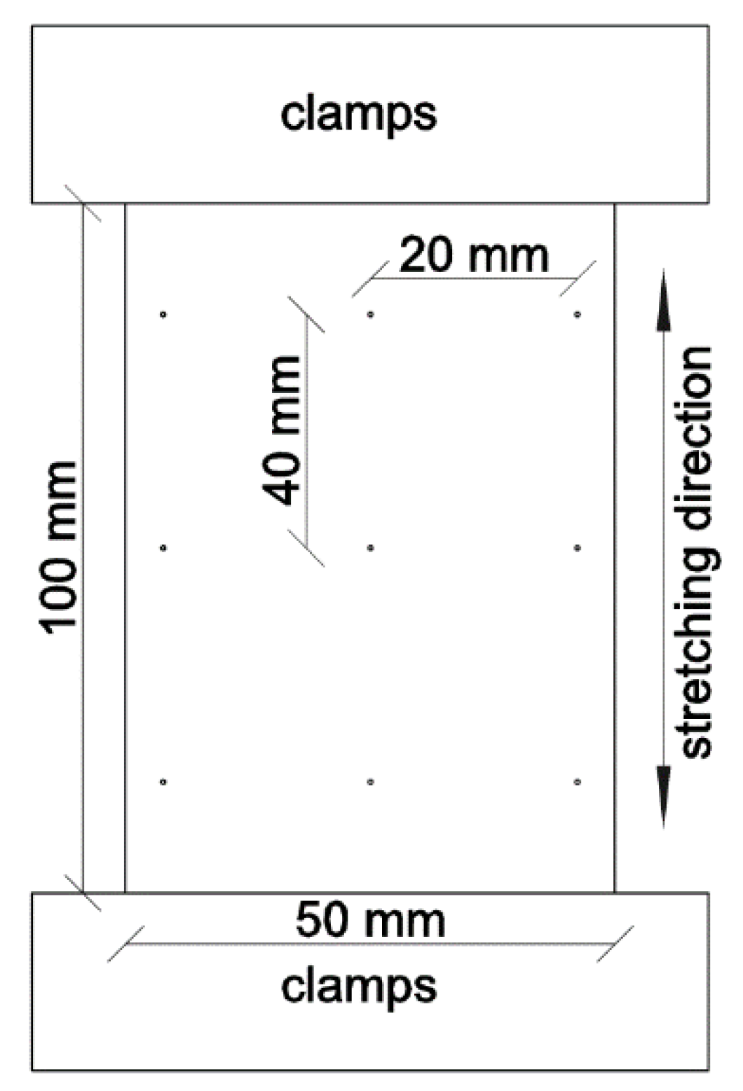
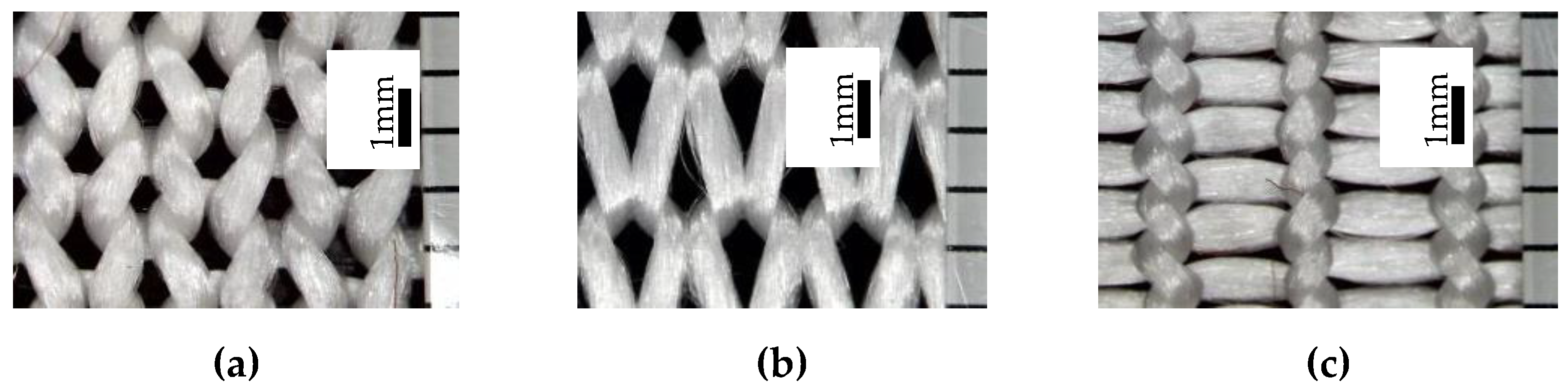
2. Materials and Methods
- through the pressure drop coefficient, where the overpressure gradient can be determined using the Expression (1):where i is the direction of the global coordinate. Index K may be found by determining the pressure drop against flow.
- through the friction index [14]. In such case, the gradient of additional pressure can be expressed by the Equation (2):where f is the coefficient of friction; Dh is the hydraulic diameter in mm.
- through the Darcy ratio (3):where C is the filling factor which is the inverse value to the permeability; μ is the viscosity of the flow [14].
3. Results and Discussions
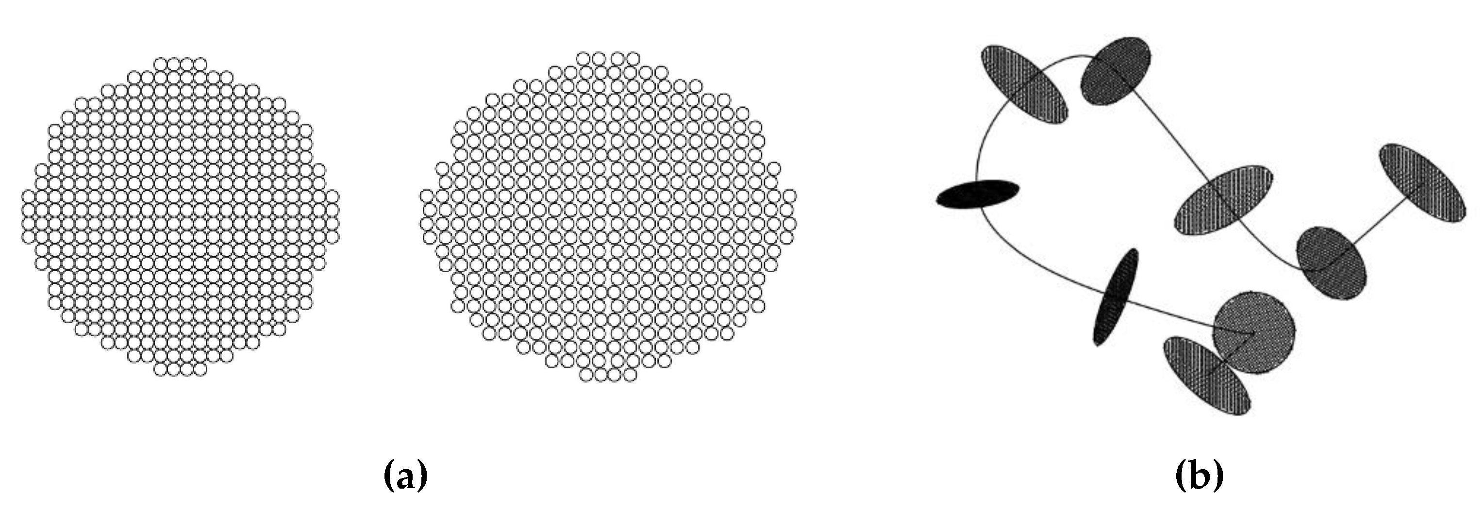
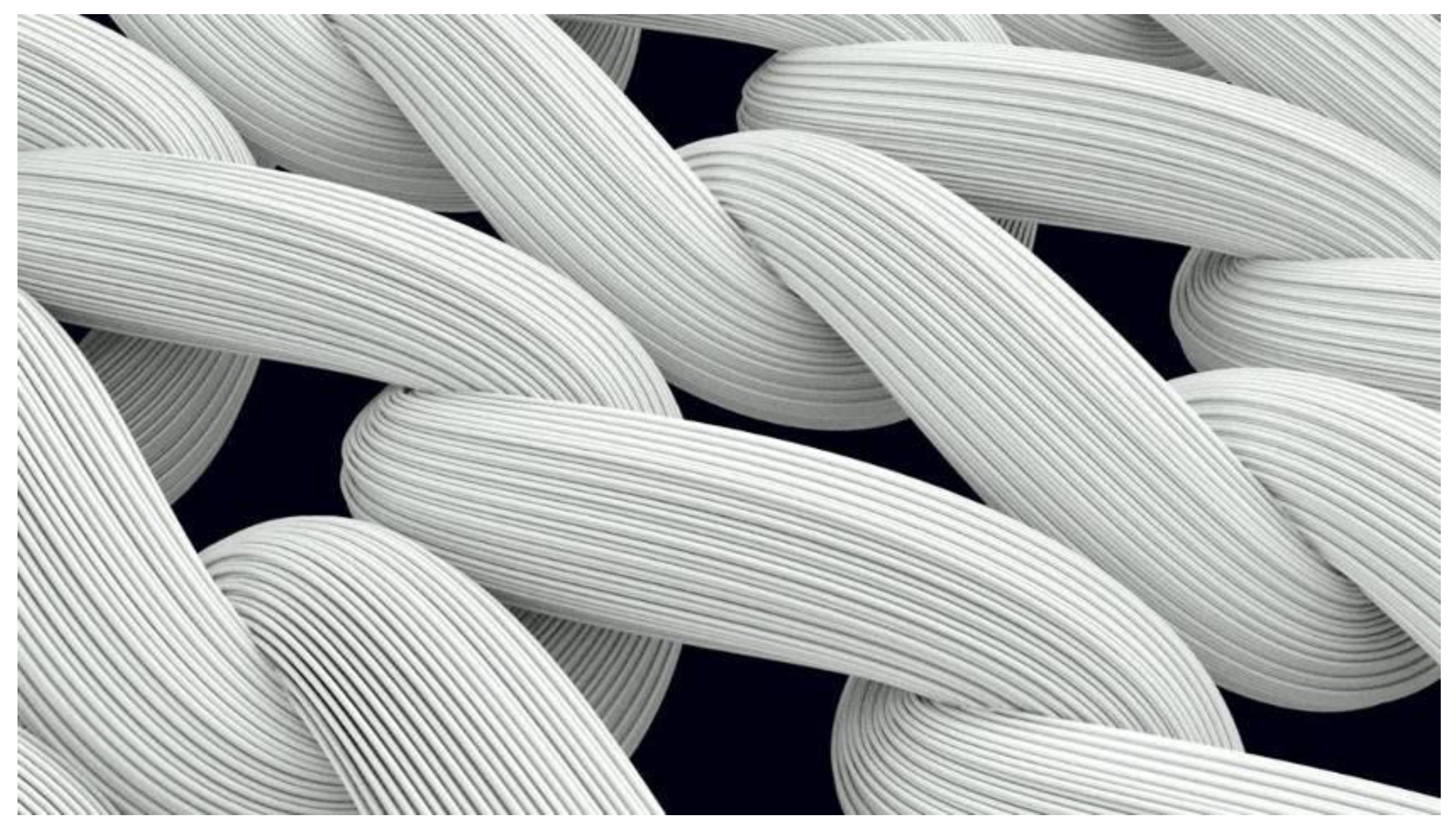
3.1. Modelling of the Knitted Loop
3.2. Determination of Air Permeability and Its Simulation
4. Conclusions
Author Contributions
Funding
Institutional Review Board Statement
Informed Consent Statement
Acknowledgments
Conflicts of Interest
References
- Bakhvalov, N.S.; Panasenko, G.P. Homogenization: Averaging Processes in Periodic Media: Mathematical Problems in the Mechanics of Composite Materials; Springer: New York, NY, USA, 1989. Available online: https://doi.org/10.1007/978-94-009-2247-1 (accessed on 1 June 2021).
- Lomov, S.; Dufort, V.; Luca, P.D.; Verpoest, I. Meso-macro integration of modeling of stiffness of textile composites. In Proceedings of the 28th International Conference of SAMPE Europe, Porte de Versailles Expo., Paris, France, 2–4 April 2007; pp. 4003–4008. [Google Scholar]
- Loginov, A.; Grishanov, S.; Harwood, R. Modelling the load-extension behavior of plain-knitted fabric. Part I: A unit-cell approach towards knitted-fabric mechanics. J. Text. Inst. 2002, 93, 218–238. [Google Scholar] [CrossRef]
- Carvelli, V.; Poggi, C. A homogenization procedure for the numerical analysis of woven fabric composites. Composites Part A 2001, 32, 1425–1432. [Google Scholar] [CrossRef]
- Talebi, H.; Silani, M.; Bordos, S.P.A.; Kerfriden, P.; Rabczuk, T. A computational library for multiscale modeling of material failure. Comput. Mech. 2014, 53, 1047–1071. [Google Scholar] [CrossRef] [Green Version]
- Khankhadjaeva, N.R. Role of Cotton Fiber in Knitting Industry. In Cotton Science and Processing Technology; Springer: Singapore, 2020; Available online: https://doi.org/10.1007/978-981-15-9169-3_11 (accessed on 1 June 2021).
- Mikučionienė, D.; Arbataitis, E. Comparative Analysis of the Influence of Bamboo and other Cellulose Fibres on Selected Structural Parameters and Physical Properties of Knitted Fabrics. Fibres Text. East. Eur. 2013, 21, 76–80. [Google Scholar]
- Bivainyte, A.; Mikucioniene, D. Influence of Shrinkage on Air and Water Vapour Permeability of Double-Layered Weft Knitted Fabrics. Mater. Sci. 2012, 18, 271–274. [Google Scholar] [CrossRef]
- Hyun, A.K.; Seung, J.K. Physical properties and wear comfort of bio-fiber-embedded yarns and their knitted fabrics according to yarn structures. Autex Res. J. 2019, 19, 279–287. [Google Scholar] [CrossRef] [Green Version]
- Wilbik-Halgas, B.; Danych, R.; Wiecek, B.; Kowalski, K. Air and water vapour permeability in double-layered knitted fabrics with different raw materials. Fibres Text. East. Eur. 2006, 14, 77–80. [Google Scholar]
- Muraliene, L.; Mikucioniene, D. Influence of structure and stretch on air permeability of compression knits. Int. J. Clothing Sci. Technol. 2020, 32, 825–835. [Google Scholar] [CrossRef]
- Špelić, I.; Rogale, D.; Mihelić Bogdanić, A. The Study on Effects of Walking on the Thermal Properties of Clothing and Subjective Comfort. Autex Res. J. 2020, 20, 228–243. [Google Scholar] [CrossRef]
- Kalendraite, B.; Krisciunaite, J.; Mikucioniene, D. Influence of sublimation process on air permeability and water absorption dynamics. Int. J. Clothing Sci. Technol. Available online: https://www.emerald.com/insight/content/doi/10.1108/IJCST-04-2020-0050/full/html (accessed on 1 June 2021). [CrossRef]
- Kukin, G.N.; Solovjov, A.N. Textile Materials Science. Chapter 3, Legkaya Industriya, Moscow Moskow. 1967, p. 226. (In Russian). Available online: https://scholar.google.com/scholar_lookup?title=Textile%20Materials%20Science&publication_year=1992&author (accessed on 1 June 2021).
- Kulichenko, A.V. Theoretical and Experimental Models for Prediction of Air –Permeability of Textile. In Proceedings of the 4th International Textile, Clothing & Design Conference, Dubrovnik, Croatia, 5–8 October 2008; pp. 799–802. [Google Scholar]
- Oğulata, R. Tugrul; Mavruz, S. Investigation of porosity and air permeability values of plain knitted fabrics. Fibres Text. East. Eur. 2010, 5, 71–75. [Google Scholar]
- Mezarciöz, S.; Mezarcioz, S.; Oğulata, R. Tugrul. Prediction of air permeability of knitted fabrics by means of computational fluid dynamics. Tekstil ve Konfeksiyon 2014, 24, 202–211. [Google Scholar]
- Xiao, X.; Zeng, X.; Long, A.; Lin, H.; Clifford, M.; Saldaeva, E. An Analytical model for through-thickness permeability of woven fabric. Textile Res. J. 2012, 82, 492–501. [Google Scholar] [CrossRef]
- Kulichenko, A.V. Theoretical Analysis, Calculation, and Prediction of the Air Permeability of Textiles. Fibre Chemistry. 2005, 37, 371–380. [Google Scholar] [CrossRef]
- Kyosev, Y.; Angelova, Y.; Kovar, R. 3D modeling of plain weft knitted structures of compressible yarn. Res J Text Appar. 2005, 9, 88–97. [Google Scholar] [CrossRef]
- Trujevcev, A.V. The Stitch Model by of Dalidovich Loop in Context of Modern Theoretic Studies. (In Russian). 2002. Available online: https://ttp.ivgpu.com/wp-content/uploads/2021/04/268_29.pdf (accessed on 1 June 2021).
- Kaldor, J.M.; James, D.L.; Marschner, S. Simulating knitted cloth at the yarn level. ACM T Graphic 2008, 27, 65. [Google Scholar]
- Wadekar, P.; Goel, P.; Amanatides, C.; Dion, G.; Kamien, R.D.; Breen, D.E. Geometric modeling of knitted fabrics using helicoid scaffolds. J. Eng. Fibers Fabr. 2020, 15, 1–15. [Google Scholar] [CrossRef]
- Ielina, T.V.; Halavska, L.Y. Development of Algorithm of Data Analysis of Topological Model of Filament in the Knitted Fabric Structure. 2013. (In Ukrainian). Available online: http://journals.khnu.km.ua/vestnik/pdf/tech/2013_3/14eli.pdf (accessed on 1 June 2021).
- Kapllani, L.; Amanatides, C.E.; Dion, G.; Shapiro, V.; Breen, D. TopoKnit: A Process-Oriented Representation for Modeling the Topology of Yarns in Weft-Knitted Textiles. Available online: https://arxiv.org/abs/2101.04560 (accessed on 1 June 2021).
- Puszkarz, A.; Krucinska, I. Modelling of air permeability of knitted fabric using the computational fluid dynamics. AUTEX Res. J. 2018, 18, 364–376. [Google Scholar] [CrossRef] [Green Version]
- Puszkarz, A.; Krucinska, I. The study of knitted fabric thermal insulation using thermography and finite volume method. Text. Res. J. 2017, 87, 643–656. [Google Scholar] [CrossRef]
- Fluid Flow Definitions. Autodesk Knowledge Network. Available online: https://knowledge.autodesk.com/support/cfd/learn-explore/caas/CloudHelp/cloudhelp/2014/ENU/SimCFD/files/GUID-4DAF0D6D-F1F4-4E90-A9C8-5CACB85E79BE-htm.html (accessed on 1 June 2021).
- Bobrova, S.; Ielina, T.; Beskin, N.; Bezsmertna, V.; Halavska, L. The use of 3D geometric models in special purpose knitwear design and predicting of its properties. Vlákna a textil (Fibres Text.) 2018, 25, 19–26. [Google Scholar]
- Ausheva, N.; Halavska, L.; Yelina, T. Geometric representation features of textile yarn in the 3D modeling systems. In Proceedings of the Scientific Conference “Unitech-13”, Gabrovo, Bulgaria, 22–23 November 2013; pp. 199–202. [Google Scholar]
- Cherous, D.A.; Shilko, S.V.; Charkovski, A.V. Prognozirovaniye effektivnykh mekhanicheskikh kharakteristik trikotazha. Fizicheskaya mekhanika 2008, 11, 107–114. (In Russian) [Google Scholar]


| Stretching Direction | Wale Spacing w, mm | Course Spacing c, mm | Yarn Diameter D, mm | Fabric Thickness M, mm | Loop Length l, mm |
|---|---|---|---|---|---|
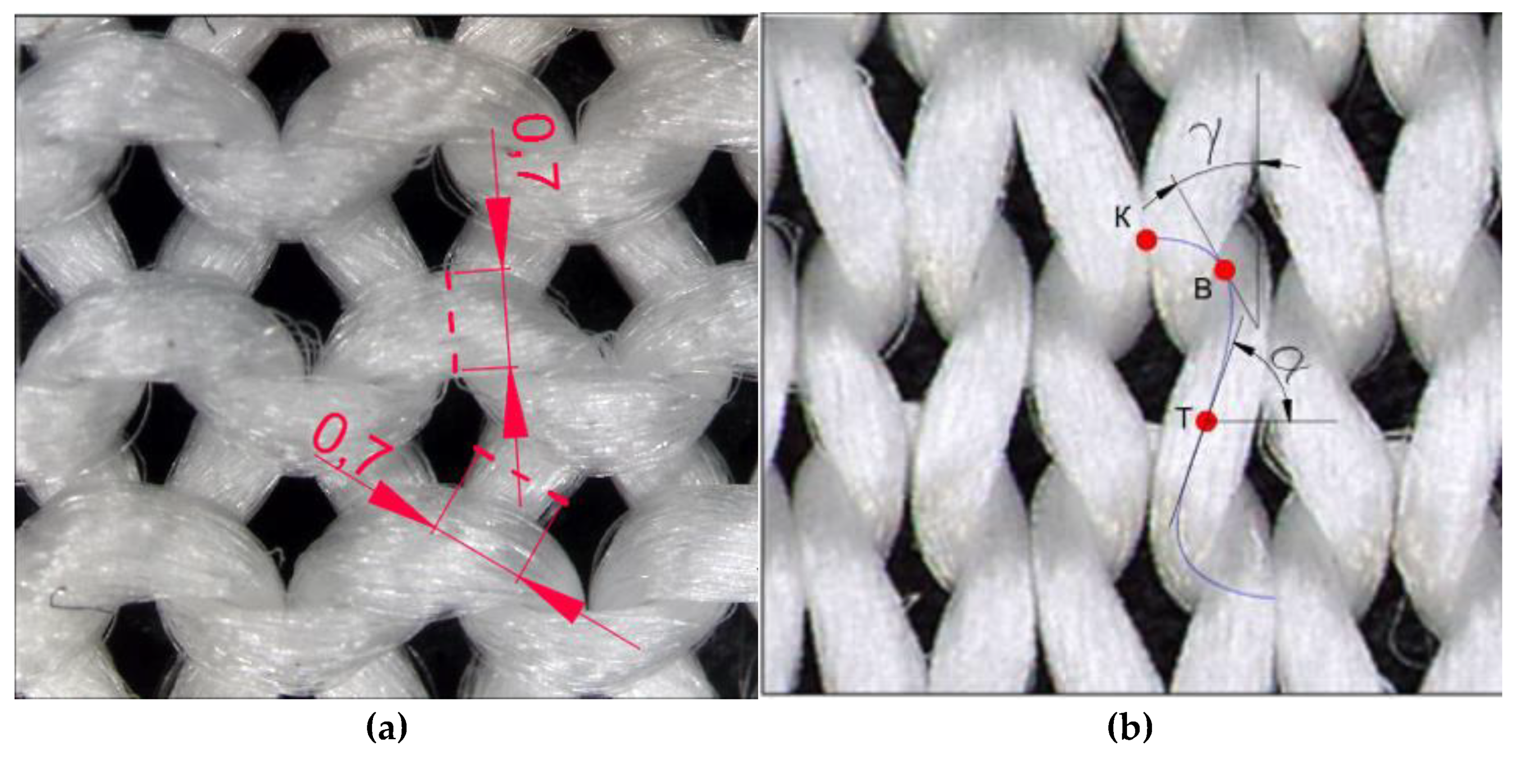
| Before stretching | 1.92 ± 0.1 | 1.85 ± 0.1 | 0.7 ± 0.05 | 0.85 ± 0.05 | 7.95 ± 0.4 |
| Stretched along wales | 1.58 ± 0.1 | 2.78 ± 0.15 | 0.75 ± 0.05 | ||
| Stretched along courses | 3.46 ± 0.2 | 0.85 ± 0.05 | 0.82 ± 0.05 |
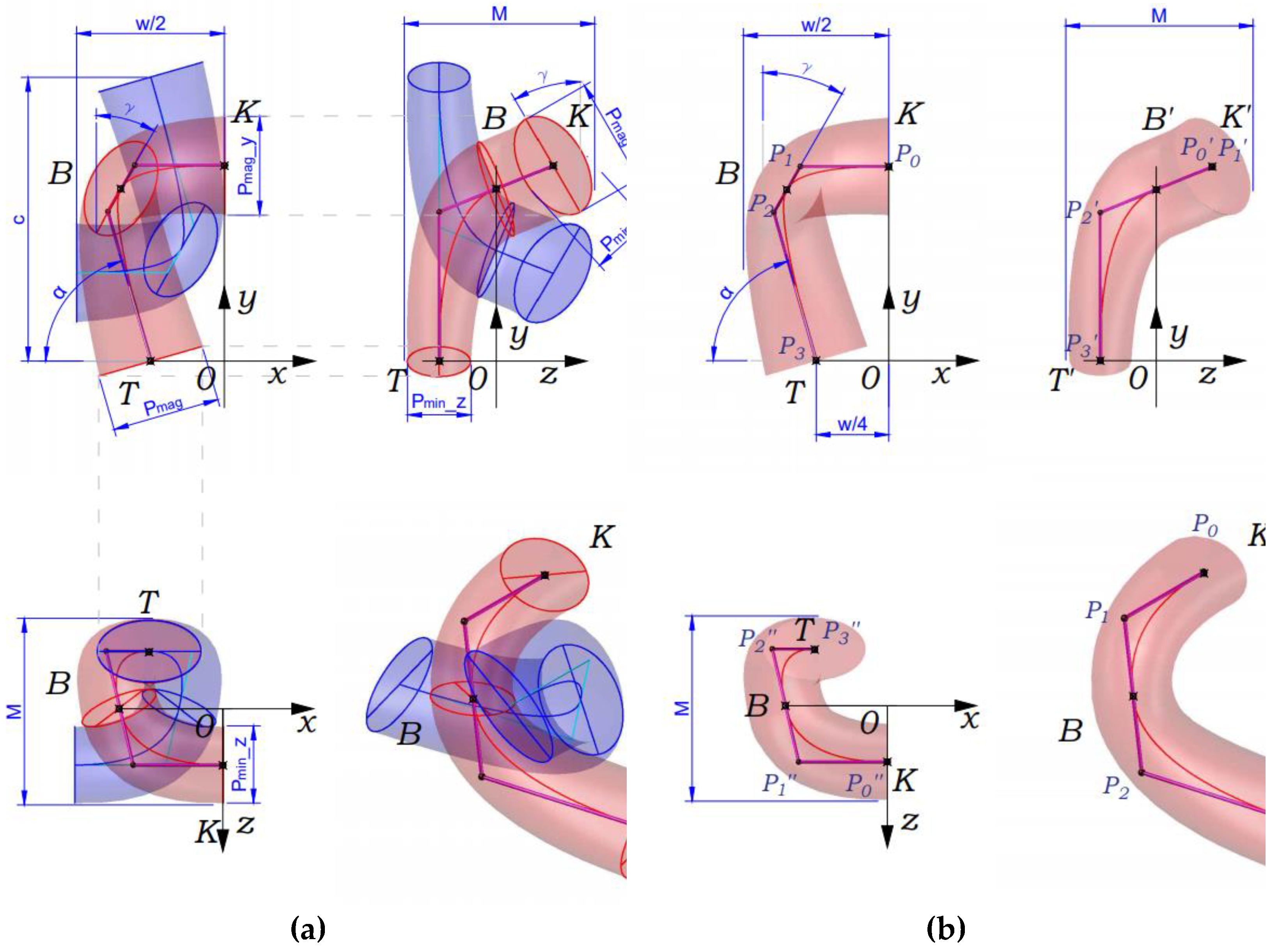
| Point | Abscissa | Ordinate | Applicata |
|---|---|---|---|
| K | |||
| B | |||
| T |
| Sample No | Experimental Value of Air Permeability, dm3/(m2s) | Simulated Value of Air Permeability, dm3/(m2s) | Discrepancy of the Simulated Value, % |
|---|---|---|---|
| 1 | 1617 | 1687 | 0.04 |
| 2 | 2353 | 2301 | −0.02 |
| 3 | 1646 | 1645 | 0.00 |
Publisher’s Note: MDPI stays neutral with regard to jurisdictional claims in published maps and institutional affiliations. |
© 2021 by the authors. Licensee MDPI, Basel, Switzerland. This article is an open access article distributed under the terms and conditions of the Creative Commons Attribution (CC BY) license (https://creativecommons.org/licenses/by/4.0/).
Share and Cite
Ielina, T.; Halavska, L.; Mikucioniene, D.; Milasius, R.; Bobrova, S.; Dmytryk, O. Development of 3D Models of Knits from Multi-Filament Ultra-Strong Yarns for Theoretical Modelling of Air Permeability. Materials 2021, 14, 3489. https://doi.org/10.3390/ma14133489
Ielina T, Halavska L, Mikucioniene D, Milasius R, Bobrova S, Dmytryk O. Development of 3D Models of Knits from Multi-Filament Ultra-Strong Yarns for Theoretical Modelling of Air Permeability. Materials. 2021; 14(13):3489. https://doi.org/10.3390/ma14133489
Chicago/Turabian StyleIelina, Tetiana, Liudmyla Halavska, Daiva Mikucioniene, Rimvydas Milasius, Svitlana Bobrova, and Oksana Dmytryk. 2021. "Development of 3D Models of Knits from Multi-Filament Ultra-Strong Yarns for Theoretical Modelling of Air Permeability" Materials 14, no. 13: 3489. https://doi.org/10.3390/ma14133489