
The Effect of Coronal Implant Design and Drilling Protocol on Bone-to-Implant Contact: A 3-Month Study in the Minipig Calvarium


Abstract
:1. Introduction
2. Materials and Methods
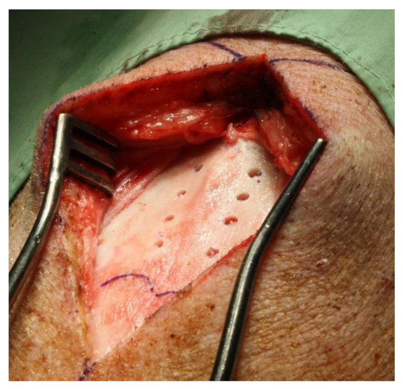
2.1. Surgical Procedure
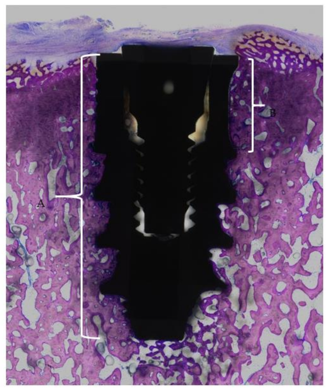
2.2. Histological Processing and Analysis
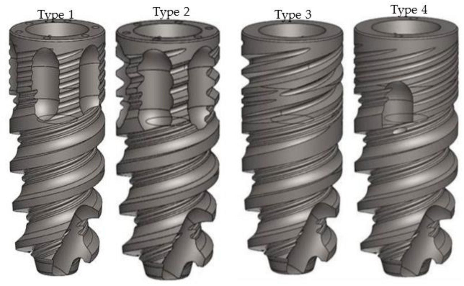
- The implant shoulder
- The apical end of the implant
- The coronal end of the flute
- The apical end of the flute
3. Results
4. Discussion
Limitations
5. Conclusions
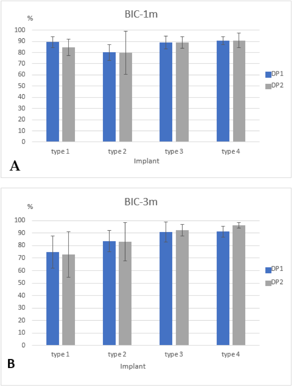
- The BIC was not affected by the drilling protocol.
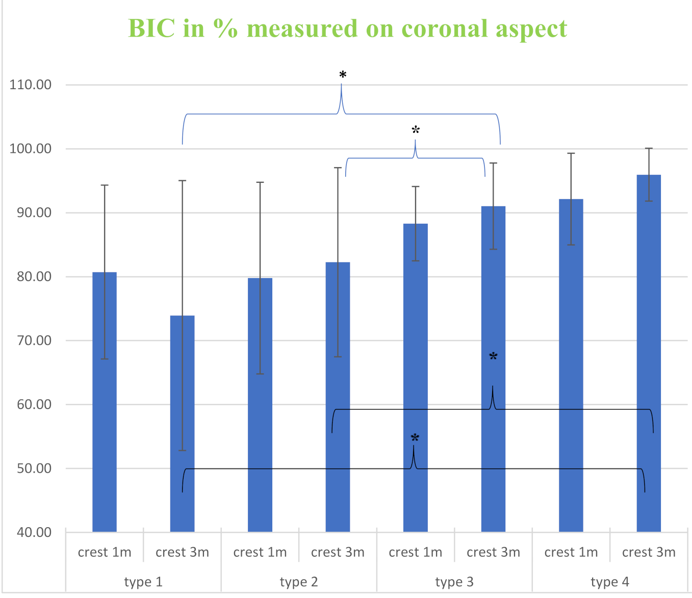
- Flutes located at the implant coronal aspect significantly impaired the crestal BIC.
- Multiple shallow microthreads were associated with a greater crestal BIC.
- Further studies should be conducted to confirm the above findings.
Author Contributions
Funding
Institutional Review Board Statement
Informed Consent Statement
Data Availability Statement
Conflicts of Interest
Abbreviations
| BIC | bone-to-implant contact |
| t-BIC | total-BIC |
| c-BIC | coronal-BIC |
| CFs | coronal flutes |
| SMs | shallow microthreads |
| DMs | deep microthreads |
| DP1 | Drilling protocol 1 |
| DP2 | Drilling protocol 2 |
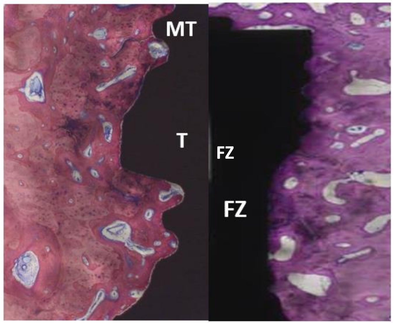
| MT | Microthread |
| T | Thread |
| FZ | flute zone |
References
- Giudice, A.; Bennardo, F.; Antonelli, A.; Barone, S.; Wagner, F.; Fortunato, L.; Traxler, H. Influence of clinician’s skill on primary implant stability with conventional and piezoelectric preparation techniques: An ex-vivo study. J. Biol. Regul. Homeost. Agents 2020, 34, 739–745. [Google Scholar] [CrossRef] [PubMed]
- Szmukler-Moncler, S.; Piattelli, A.; Favero, G.A.; Dubruille, J.H. Considerations preliminary to the application of early and immediate loading protocols in dental implantology. Clin. Oral Implants Res. 2000, 11, 12–25. [Google Scholar] [CrossRef] [PubMed]
- Fernandes, M.; Fonseca, E. Thermal analysis in drilling of ex vivo bovine bones. J. Mech. Med. Biol. 2017, 17, 1750082-16. [Google Scholar] [CrossRef]
- Trisi, P.; Perfetti, G.; Baldoni, E.; Berardi, D.; Colagiovanni, M.; Scogna, G. Implant micromotion is related to peak insertion torque and bone density. Clin. Oral Implants Res. 2009, 20, 467–471. [Google Scholar] [CrossRef] [PubMed]
- Trisi, P.; De Benedittis, S.; Perfetti, G.; Berardi, D. Primary stability, insertion torque and bone density of cylindric implant ad modum Branemark: Is there a relationship? An in vitro study. Clin. Oral Implants Res. 2011, 22, 567–570. [Google Scholar] [CrossRef]
- Marquezan, M.; Osório, A.; Sant’Anna, E.; Souza, M.M.; Maia, L. Does bone mineral density influence the primary stability of dental implants? A systematic review. Clin. Oral Implants Res. 2012, 23, 767–774. [Google Scholar] [CrossRef]
- Tabassum, A.; Meijer, G.J.; Wolke, J.G.; Jansen, J.A. Influence of surgical technique and surface roughness on the primary stability of an implant in artificial bone with different cortical thickness: A laboratory study. Clin. Oral Implants Res. 2010, 21, 213–220. [Google Scholar] [CrossRef]
- Tabassum, A.; Meijer, G.J.; Wolke, J.G.; Jansen, J.A. Influence of the surgical technique and surface roughness on the primary stability of an implant in artificial bone with a density equivalent to maxillary bone: A laboratory study. Clin. Oral Implants Res. 2009, 20, 327–332. [Google Scholar] [CrossRef]
- Berglundh, T.; Abrahamsson, I.; Lang, N.P.; Lindhe, J. De novo alveolar bone formation adjacent to endosseous implants. Clin. Oral Implants Res. 2003, 14, 251–262. [Google Scholar] [CrossRef]
- Turkyilmaz, I.; Aksoy, U.; McGlumphy, E.A. Two alternative surgical techniques for enhancing primary implant stability in the posterior maxilla: A clinical study including bone density, insertion torque, and resonance frequency analysis data. Clin. Implant Dent. Relat. Res. 2008, 10, 231–237. [Google Scholar] [CrossRef]
- Bashutski, J.D.; D’Silva, N.J.; Wang, H.L. Implant compression necrosis: Current understanding and case report. J. Periodontol. 2009, 80, 700–704. [Google Scholar] [CrossRef] [PubMed]
- O’Sullivan, D.; Sennerby, L.; Meredith, N. Measurements comparing the initial stability of five designs of dental implants: A human cadaver study. Clin. Implant Dent. Relat. Res. 2000, 2, 85–92. [Google Scholar] [CrossRef]
- Duyck, J.; Roesems, R.; Cardoso, M.V.; Ogawa, T.; De Villa Camargos, G.; Vandamme, K. Effect of insertion torque on titanium implant osseointegration: An animal experimental study. Clin. Oral Implants Res. 2015, 26, 191–196. [Google Scholar] [CrossRef]
- Coelho, P.G.; Marin, C.; Teixeira, H.S.; Campos, F.E.; Gomes, J.B.; Guastaldi, F.; Anchieta, R.B.; Silveira, L.; Bonfante, E.A. Biomechanical evaluation of undersized drilling on implant biomechanical stability at early implantation times. J. Oral Maxillofac. Surg. 2013, 71, e69–e75. [Google Scholar] [CrossRef] [PubMed]
- Trisi, P.; Todisco, M.; Consolo, U.; Travaglini, D. High versus low implant insertion torque: A histologic, histomorphometric, and biomechanical study in the sheep mandible. Int. J. Oral Maxillofac. Implants 2011, 26, 837–849. [Google Scholar]
- Cohen, O.; Ormianer, Z.; Tal, H.; Rothamel, D.; Weinreb, M.; Moses, O. Differences in crestal bone-to-implant contact following an under-drilling compared to an over-drilling protocol. A study in the rabbit tibia. Clin. Oral Investig. 2016, 20, 2475–2480. [Google Scholar] [CrossRef] [PubMed]
- Steigenga, J.T.; Al-Shammari, K.F.; Nociti, F.H.; Misch, C.E.; Wang, H.L. Dental implant design and its relationship to long-term implant success. Implant Dent. 2003, 12, 306–317. [Google Scholar] [CrossRef]
- Baumgart, F.W.; Cordey, J.; Morikawa, K.; Perren, S.M.; Rahn, B.A.; Schavan, R.; Snyder, S. AO/ASIF self-tapping screws (STS). Injury 1993, 24 (Suppl. 1), S1–S17. [Google Scholar] [CrossRef]
- Bickley, M.B.; Hanel, D.P. Self-tapping versus standard tapped titanium screw fixation in the upper extremity. J. Hand Surg. Am. 1998, 23, 308–311. [Google Scholar] [CrossRef]
- Wu, S.W.; Lee, C.C.; Fu, P.Y.; Lin, S.C. The effects of flute shape and thread profile on the insertion torque and primary stability of dental implants. Med. Eng. Phys. 2012, 34, 797–805. [Google Scholar] [CrossRef]
- Hansson, S.; Werke, M. The implant thread as a retention element in cortical bone: The effect of thread size and thread profile: A finite element study. J. Biomech. 2003, 36, 1247–1258. [Google Scholar] [CrossRef]
- Frost, H.M. Skeletal structural adaptations to mechanical usage (SATMU): 2. Redefining Wolff’s law: The remodeling problem. Anat. Rec. 1990, 226, 414–422. [Google Scholar] [CrossRef] [PubMed]
- Chowdhary, R.; Halldin, A.; Jimbo, R.; Wennerberg, A. Influence of micro threads alteration on osseointegration and primary stability of implants: An FEA and in vivo analysis in rabbits. Clin. Implant Dent. Relat. Res. 2015, 17, 562–569. [Google Scholar] [CrossRef] [PubMed]
- Schrotenboer, J.; Tsao, Y.P.; Kinariwala, V.; Wang, H.L. Effect of microthreads and platform switching on crestal bone stress levels: A finite element analysis. J. Periodontol. 2008, 79, 2166–2172. [Google Scholar] [CrossRef]
- Metzler, P.; von Wilmowsky, C.; Stadlinger, B.; Zemann, W.; Schlegel, K.A.; Rosiwal, S.; Rupprecht, S. Nano-crystalline diamond-coated titanium dental implants—A histomorphometric study in adult domestic pigs. J. Craniomaxillofac. Surg. 2013, 41, 532–538. [Google Scholar] [CrossRef]
- Freilich, M.; Wen, B.; Shafer, D.; Schleier, P.; Dard, M.; Pendrys, D.; Ortiz, D.; Kuhn, L. Implant-guided vertical bone growth in the mini-pig. Clin. Oral Implants Res. 2012, 23, 751–757. [Google Scholar] [CrossRef]
- Romero-Ruiz, M.M.; Gil-Mur, F.J.; Ríos-Santos, J.V.; Lázaro-Calvo, P.; Ríos-Carrasco, B.; Herrero-Climent, M. Influence of a novel surface of bioactive implants on osseointegration: A comparative and histomorfometric correlation and implant stability study in minipigs. Int. J. Mol. Sci. 2019, 20, 2307. [Google Scholar] [CrossRef] [PubMed]
- Kilkenny, C.; Browne, W.J.; Cuthill, I.C.; Emerson, M.; Altman, D.G. Improving bioscience research reporting: The ARRIVE guidelines for reporting animal research. PLoS Biol. 2010, 8, e1000412. [Google Scholar] [CrossRef]
- Bosshardt, D.D.; Bergomi, M.; Vaglio, G.; Wiskott, A. Regional structural characteristics of bovine periodontal ligament samples and their suitability for biomechanical tests. J. Anat. 2008, 212, 319–329. [Google Scholar] [CrossRef]
- Danz, J.C.; Habegger, M.; Bosshardt, D.D.; Katsaros, C.; Stavropoulos, A. Virtual tissue alignment and cutting plane definition--a new method to obtain optimal longitudinal histological sections. J. Anat. 2014, 224, 85–94. [Google Scholar] [CrossRef]
- Janner, S.F.M.; Bosshardt, D.D.; Cochran, D.L.; Chappuis, V.; Huynh-Ba, G.; Jones, A.A.; Buser, D. The influence of collagen membrane and autogenous bone chips on bone augmentation in the anterior maxilla: A preclinical study. Clin. Oral Implants Res. 2017, 28, 1368–1380. [Google Scholar] [CrossRef]
- Kwon, Y.S.; Namgoong, H.; Kim, J.H.; Cho, I.H.; Kim, M.D.; Eom, T.G.; Koo, K.T. Effect of microthreads on removal torque and bone-to-implant contact: An experimental study in miniature pigs. J. Periodontal. Implant Sci. 2013, 43, 41–46. [Google Scholar] [CrossRef]
- Venturelli, A. A modified surgical protocol for placing implants in the maxillary tuberosity: Clinical results at 36 months after loading with fixed partial dentures. Int. J. Oral Maxillofac. Implants 1996, 11, 743–749. [Google Scholar]
- Martinez, H.; Davarpanah, M.; Missika, P.; Celletti, R.; Lazzara, R. Optimal implant stabilization in low density bone. Clin. Oral Implants Res. 2001, 12, 423–432. [Google Scholar] [CrossRef] [PubMed]
- Bilhan, H.; Geckili, O.; Mumcu, E.; Bozdag, E.; Sünbüloğlu, E.; Kutay, O. Influence of surgical technique, implant shape and diameter on the primary stability in cancellous bone. J. Oral Rehabil. 2010, 37, 900–907. [Google Scholar] [CrossRef] [PubMed]
- Huang, H.M.; Chee, T.J.; Lew, W.Z.; Feng, S.W. Modified surgical drilling protocols influence osseointegration performance and predict value of implant stability parameters during implant healing process. Clin. Oral Investig. 2020, 24, 3445–3455. [Google Scholar] [CrossRef] [PubMed]
- Lee, D.W.; Choi, Y.S.; Park, K.H.; Kim, C.S.; Moon, I.S. Effect of microthread on the maintenance of marginal bone level: A 3-year prospective study. Clin. Oral Implants Res. 2007, 18, 465–470. [Google Scholar] [CrossRef]
- Abrahamsson, I.; Berglundh, T. Tissue characteristics at microthreaded implants: An experimental study in dogs. Clin. Implant Dent. Relat. Res. 2006, 8, 107–113. [Google Scholar] [CrossRef]
- Geramizadeh, M.; Katoozian, H.; Amid, R.; Kadkhodazadeh, M. Three-dimensional optimization and sensitivity analysis of dental implant thread parameters using finite element analysis. J. Korean Assoc. Oral Maxillofac. Surg. 2018, 44, 59–65. [Google Scholar] [CrossRef]
- Cattoni, F.; Teté, G.; Calloni, A.M.; Manazza, F.; Gastaldi, G.; Capparè, P. Milled versus moulded mock-ups based on the superimposition of 3D meshes from digital oral impressions: A comparative in vitro study in the aesthetic area. BMC Oral Health 2019, 19, 230. [Google Scholar] [CrossRef]
- Capparè, P.; Tetè, G.; Sberna, M.T.; Panina-Bordignon, P. The Emerging Role of Stem Cells in Regenerative Dentistry. Curr. Gene Ther. 2020, 20, 259–268. [Google Scholar] [CrossRef] [PubMed]
- Tecco, S.; Parisi, M.R.; Gastaldi, G.; Polizzi, E.; D’Amicantonio, T.; Zilocchi, I.; Gardini, I.; Gherlone, E.F.; Lazzarin, A.; Capparè, P. Point-of-care testing for hepatitis C virus infection at an Italian dental clinic: Portrait of the pilot study population. New Microbiol. 2019, 42, 133–138. [Google Scholar] [PubMed]


| Implant Type 1 | Implant Type 2 | Implant Type 3 | Implant Type 4 | ||
|---|---|---|---|---|---|
| 1 month | DP1 | 89.47 ± 4.87 | 80.03 ± 7.26 | 88.92 ± 5.69 | 90.58 ± 3.34 |
| DP2 | 84.73 ± 7.39 | 79.64 ± 19.16 | 88.90 ± 5.06 | 90.78 ± 6.38 | |
| 3 months | DP1 | 74.66 ± 12.93 | 83.68 ± 8.59 | 91.02 ± 8.05 | 91.31 ± 4.38 |
| DP2 | 72.78 ± 18.28 | 82.93 ± 15.27 | 92.41 ± 4.47 | 96.17 ± 2.26 |
| Implant Type 1 | Implant Type 2 | Implant Type 3 | Implant Type 4 | |
|---|---|---|---|---|
| 1 month | 80.73 ± 13.60 | 79.78 ± 14.99 | 88.30 ± 5.81 | 92.15 ± 6.21 |
| 3 months | 73.92 ± 21.11 | 82.27 ± 14.79 | 91.04 ± 6.75 | 95.96 ± 4.13 |
Publisher’s Note: MDPI stays neutral with regard to jurisdictional claims in published maps and institutional affiliations. |
© 2021 by the authors. Licensee MDPI, Basel, Switzerland. This article is an open access article distributed under the terms and conditions of the Creative Commons Attribution (CC BY) license (https://creativecommons.org/licenses/by/4.0/).
Share and Cite
Cohen, O.; Bosshardt, D.D.; Weinberg, E.; Slutzkey, G.; Moses, O. The Effect of Coronal Implant Design and Drilling Protocol on Bone-to-Implant Contact: A 3-Month Study in the Minipig Calvarium. Materials 2021, 14, 2645. https://doi.org/10.3390/ma14102645
Cohen O, Bosshardt DD, Weinberg E, Slutzkey G, Moses O. The Effect of Coronal Implant Design and Drilling Protocol on Bone-to-Implant Contact: A 3-Month Study in the Minipig Calvarium. Materials. 2021; 14(10):2645. https://doi.org/10.3390/ma14102645
Chicago/Turabian StyleCohen, Omer, Dieter D. Bosshardt, Evegeny Weinberg, Gil Slutzkey, and Ofer Moses. 2021. "The Effect of Coronal Implant Design and Drilling Protocol on Bone-to-Implant Contact: A 3-Month Study in the Minipig Calvarium" Materials 14, no. 10: 2645. https://doi.org/10.3390/ma14102645