Investigation of Microstructure and Nanoindentation Hardness of C+ & He+ Irradiated Nanocrystal SiC Coatings during Annealing and Corrosion

 ,
,
Abstract
:1. Introduction
2. Materials and Experimental Methods
2.1. Sample Preparation
2.2. Irradiation, Annnealing and Corrosion Tests
2.3. Analysis and Measurement Methods
3. Results and Discussion
3.1. Microstructure of Unirradiated and Irradiated SiC Coating
3.2. Microstructure of Annealed SiC Coating
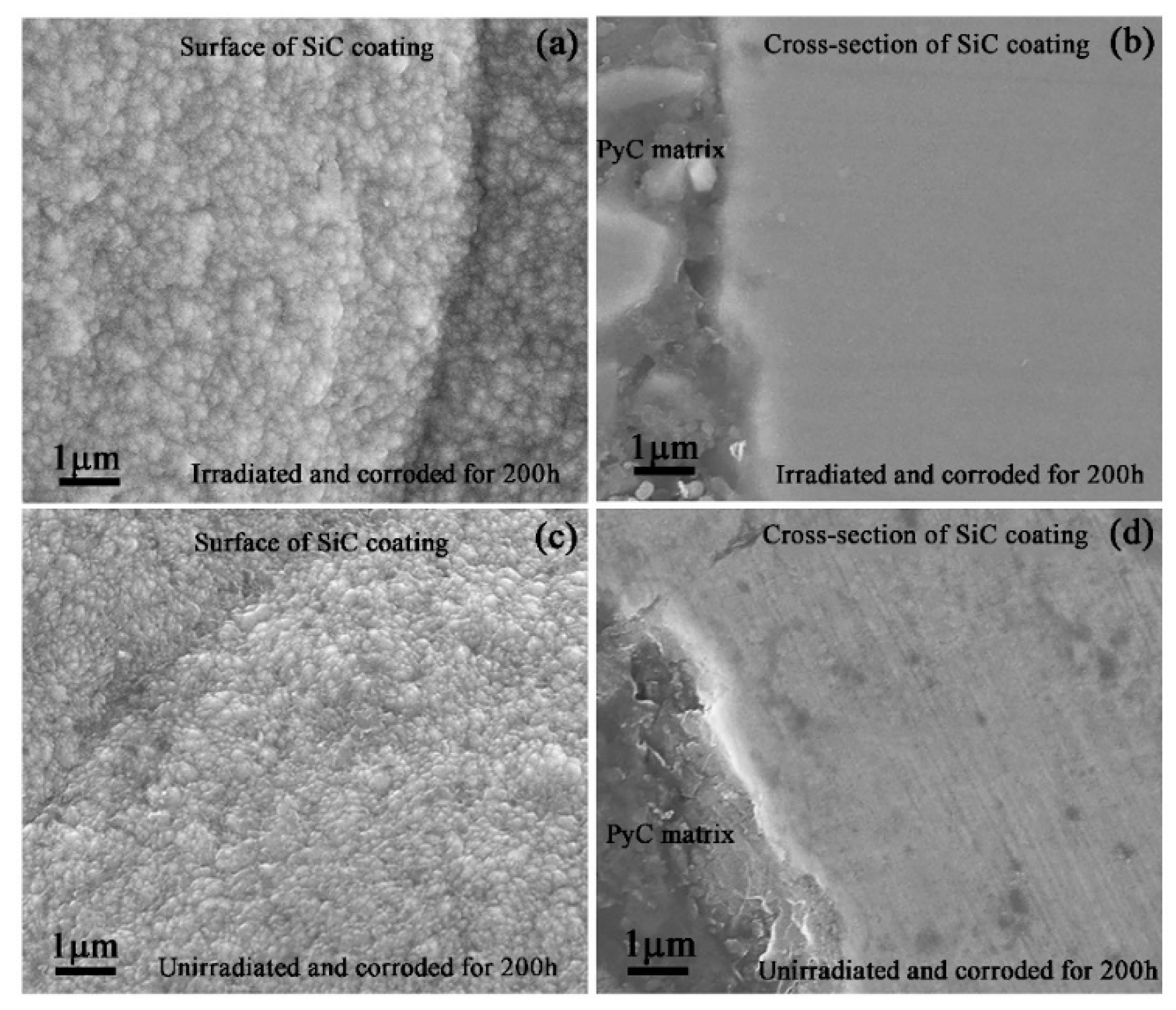
3.3. Microstructure Analysis of Corroded SiC Coating
3.4. Nanoindentation Results of SiC Coatings in the States of Irradiation, Annealing and Corrosion
4. Conclusions
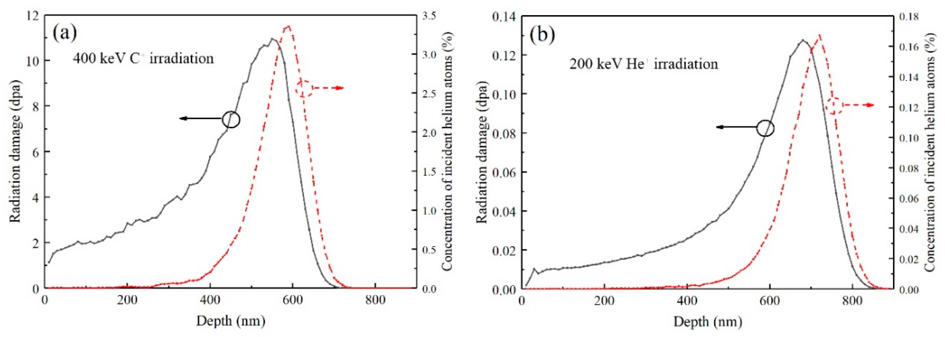
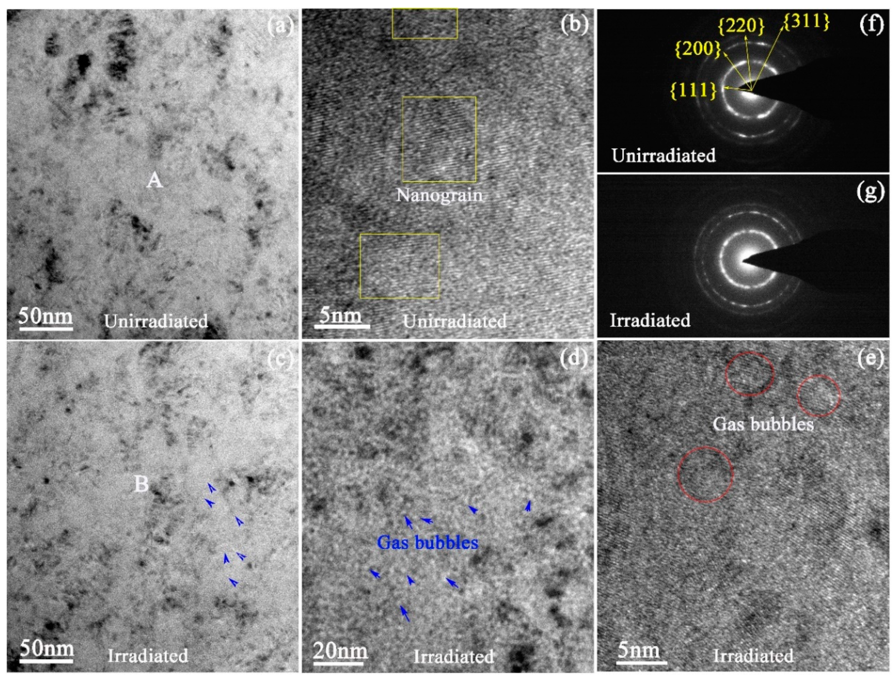
- C+ and He+ irradiation did not cause obvious amorphous transformation of nanocrystalline SiC coating, although the peak irradiation damage was up to 10 dpa. In the peak region of the injected helium concentration, helium bubbles with the size of 2–3 nm were uniformly distributed in the SiC matrix.
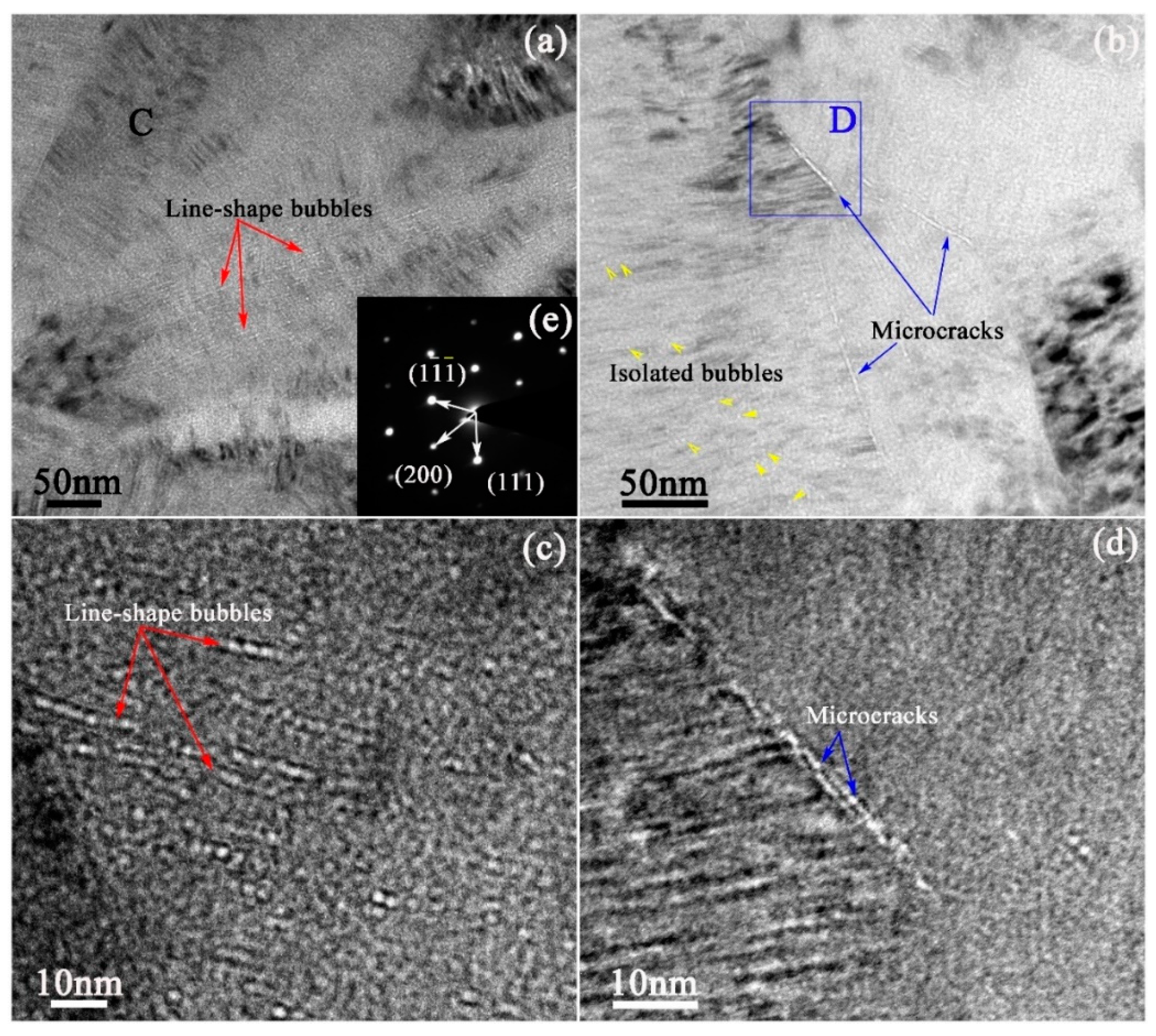
- High temperature annealing resulted in the transformation of SiC nanocrystals into columnar crystals in the irradiated region and caused a significant change in the size and distribution of helium bubbles. Line-shaped bubble bands formed at the columnar crystal boundaries and their stacking fault planes and made the formation of microcracks of hundreds of nanometers in length at the columnar crystal boundaries. Meanwhile, some isolated helium bubbles distributed in SiC grains still maintained the size of 2–3 nm, although annealed at 1200 °C for 5 h.
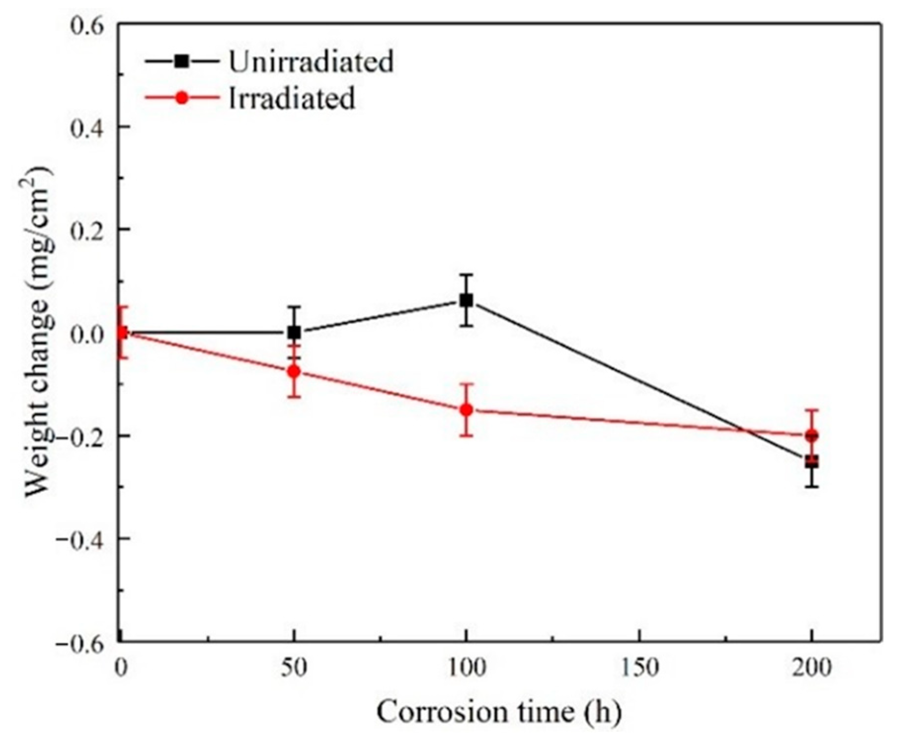
- SiC coating showed an excellent corrosion resistance under high-temperature, high-pressure water. The weight of the sample decreased with the increase of corrosion time. Moreover, under the same corrosion time, the weight loss of the sample irradiated by C+ and He+ was greater than that of the unirradiated sample, which was due to the fact that ion irradiation promoted the corrosion of the SiC coating.
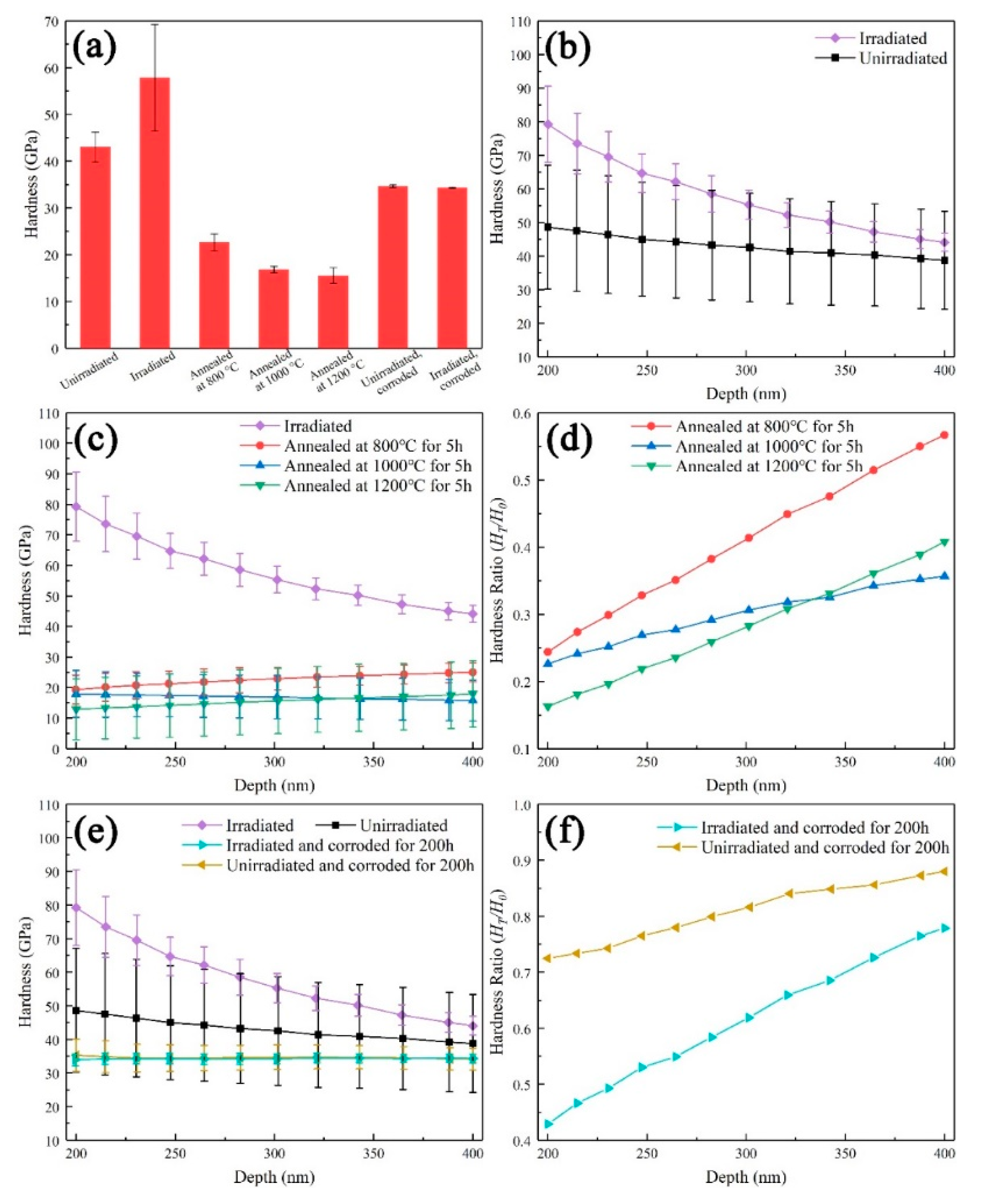
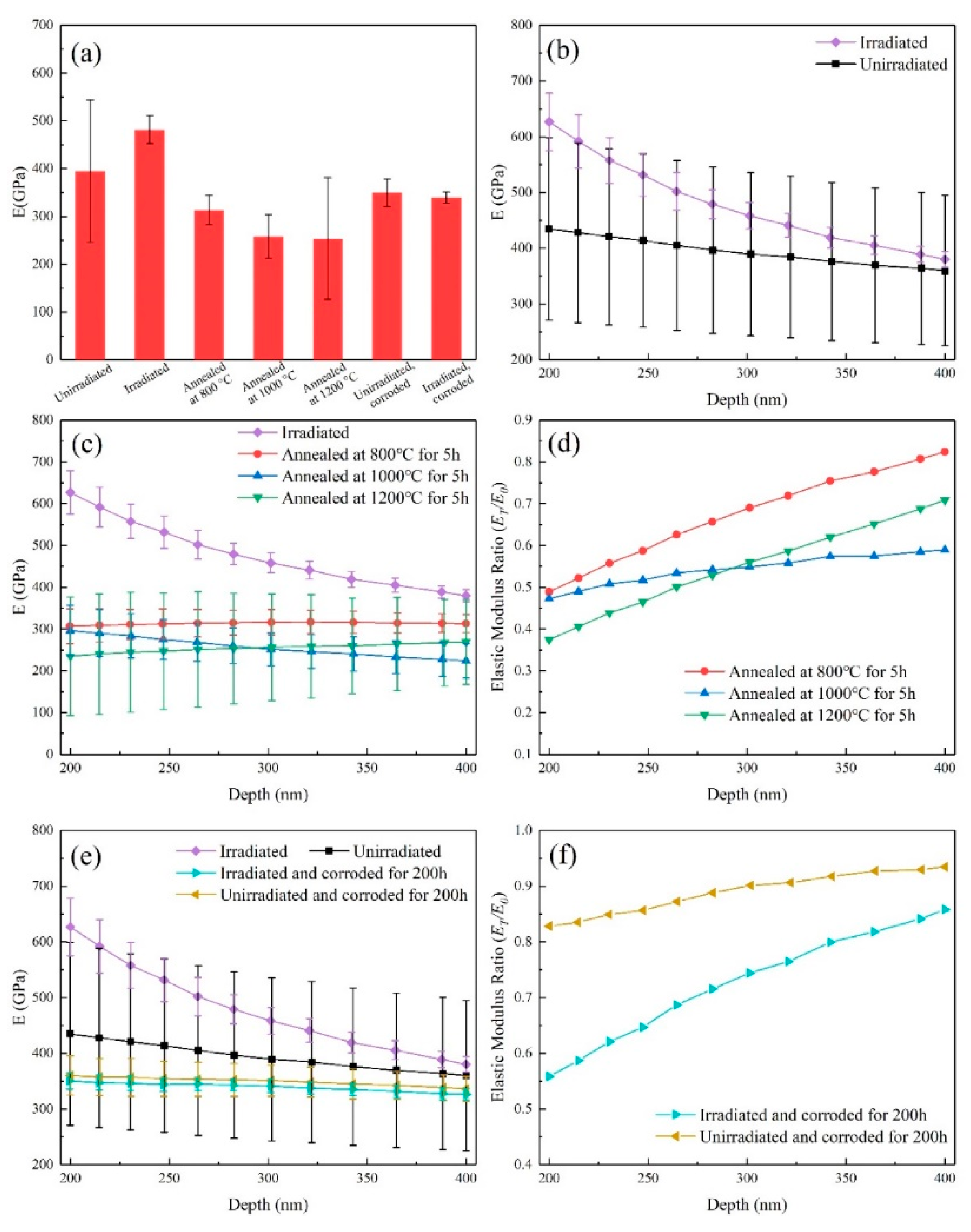
- The nanoindentation hardness and the elastic modulus of SiC coating increased significantly with C+ and He+ irradiation, while their values decreased with high-temperature annealing. Moreover, the higher the annealing temperature was, the greater the reduction in the values. Corrosion caused the decrease of nanoindentation hardness and the elastic modulus in the whole test depth range, whether the samples were irradiated or unirradiated.
Author Contributions
Funding
Conflicts of Interest
References
- Duan, Z.; Yang, H.; Satoh, Y.; Murakami, K.; Kano, S.; Zhao, Z.; Shen, J.; Abe, H. Current status of materials development of nuclear fuel cladding tubes for light water reactors. Nucl. Eng. Des. 2017, 316, 131–150. [Google Scholar] [CrossRef]
- Terrani, K.A. Accident tolerant fuel cladding development: Promise, status, and challenges. J. Nucl. Mater. 2018, 501, 13–30. [Google Scholar] [CrossRef]
- Zinkle, S.J.; Was, G.S. Materials challenges in nuclear energy. Acta Mater. 2013, 61, 735–758. [Google Scholar] [CrossRef]
- Park, D.J.; Kim, H.G.; Jung, Y.I.; Park, J.H.; Yang, J.H.; Koo, Y.H. Behavior of an improved Zr fuel cladding with oxidation resistant coating under loss-of-coolant accident conditions. J. Nucl. Mater. 2016, 482, 75–82. [Google Scholar] [CrossRef]
- Zinkle, S.J.; Terrani, K.A.; Gehin, J.C.; Ott, L.J.; Snead, L.L. Accident tolerant fuels for LWRs: A perspective. J. Nucl. Mater. 2014, 448, 374–379. [Google Scholar] [CrossRef]
- Kim, H.-G.; Yang, J.-H.; Kim, W.-J.; Koo, Y.-H. Development Status of Accident-tolerant Fuel for Light Water Reactors in Korea. Nucl. Eng. Technol. 2016, 48, 1–15. [Google Scholar] [CrossRef] [Green Version]
- Agarwal, S.; Duscher, G.; Zhao, Y.; Crespillo, M.L.; Katoh, Y.; Weber, W.J. Multiscale characterization of irradiation behaviour of ion-irradiated SiC/SiC composites. Acta Mater. 2018, 161, 207–220. [Google Scholar] [CrossRef]
- Zayachuk, Y.; Karamched, P.; Deck, C.; Hosemann, P.; Armstrong, D.E.J. Linking microstructure and local mechanical properties in SiC-SiC fiber composite using micromechanical testing. Acta Mater. 2019, 168, 178–189. [Google Scholar] [CrossRef]
- Zhang, W.; Wang, M.; Wang, L.; Liu, C.H.; Chang, H.; Yang, J.J.; Liao, J.L.; Yang, Y.Y.; Liu, N. Interface stability, mechanical and corrosion properties of AlCrMoNbZr/(AlCrMoNbZr)N high-entropy alloy multilayer coatings under helium ion irradiation. Appl. Surf. Sci. 2019, 485, 108–118. [Google Scholar] [CrossRef]
- Sun, Z.; Edmondson, P.D.; Yamamoto, Y. Effects of Laves phase particles on recovery and recrystallization behaviors of Nb-containing FeCrAl alloys. Acta Mater. 2018, 144, 716–727. [Google Scholar] [CrossRef]
- Haley, J.C.; Briggs, S.A.; Edmondson, P.D.; Sridharan, K.; Roberts, S.G.; Lozano-Perez, S.; Field, K.G. Dislocation loop evolution during in-situ ion irradiation of model FeCrAl alloys. Acta Mater. 2017, 136, 390–401. [Google Scholar] [CrossRef]
- Brachet, J.-C.; Idarraga-Trujillo, I.; Flem, M.L.; Saux, M.L.; Vandenberghe, V.; Urvoy, S.; Rouesne, E.; Guilbert, T.; Toffolon-Masclet, C.; Tupin, M.; et al. Early studies on Cr-Coated Zircaloy-4 as enhanced accident tolerant nuclear fuel claddings for light water reactors. J. Nucl. Mater. 2019, 517, 268–285. [Google Scholar] [CrossRef]
- Kashkarov, E.B.; Nikitenkov, N.N.; Syrtanov, M.S.; Sutygina, A.N.; Shulepov, I.A.; Lider, A.M. Influence of plasma immersion titanium implantation on hydrogenation and mechanical properties of Zr–2.5Nb. Appl. Surf. Sci. 2016, 370, 142–148. [Google Scholar] [CrossRef]
- Wang, Y.M.; Feng, W.; Xing, Y.R.; Ge, Y.L.; Guo, L.X.; Ouyang, J.H.; Jia, D.C.; Zhou, Y. Degradation and structure evolution in corrosive LiOH solution of microarc oxidation coated Zircaloy-4 alloy in silicate and phosphate electrolytes. Appl. Surf. Sci. 2018, 431, 2–12. [Google Scholar] [CrossRef]
- Ran, G.; Xu, J.; Shen, Q.; Zhang, J.; Li, N.; Wang, L. In situ TEM observation of growth behavior of Kr bubbles in zirconium alloy during post-implantation annealing. Nucl. Instrum. Methods B 2013, 307, 516–521. [Google Scholar] [CrossRef]
- Lei, P.; Ran, G.; Liu, C.; Shen, Q.; Zhang, R.; Ye, C.; Li, N.; Yang, P.; Yang, Y. Microstructure analysis of Kr+ irradiation and post-irradiation corrosion of modified N36 zirconium alloy. Nucl. Instrum. Methods B 2017, 406, 648–655. [Google Scholar] [CrossRef]
- Ryabchikov, A.I.; Kashkarov, E.B.; Pushilina, N.S.; Syrtanov, M.S.; Shevelev, A.E.; Korneva, O.S.; Sutygina, A.N.; Lider, A.M. High-intensity low energy titanium ion implantation into zirconium alloy. Appl. Surf. Sci. 2018, 439, 106–112. [Google Scholar] [CrossRef]
- Yang, S.; Guo, Z.; Zhao, L.; Zhao, L.; Guan, Q.; Liu, Y. Surface microstructures and high-temperature high-pressure corrosion behavior of N18 zirconium alloy induced by high current pulsed electron beam irradiation. Appl. Surf. Sci. 2019, 484, 453–460. [Google Scholar] [CrossRef]
- Tang, C.; Stueber, M.; Seifert, H.J.; Steinbrueck, M. Protective coatings on zirconium-based alloys as accident-tolerant fuel (ATF) claddings. Corros. Rev. 2017, 35, 141–165. [Google Scholar] [CrossRef]
- Jiang, L.; Xiu, P.; Yan, Y.; Lu, C.; Huang, M.; Liu, T.; Ye, C.; Sun, H.; Shu, R.; Wang, L. Effects of ion irradiation on chromium coatings of various thicknesses on a zirconium alloy. J. Nucl. Mater. 2019, 526, 151740. [Google Scholar] [CrossRef]
- Hu, X.; Dong, C.; Wang, Q.; Chen, B.; Yang, H.; Wei, T.; Zhang, R.; Gu, W.; Chen, D. High-temperature oxidation of thick Cr coating prepared by arc deposition for accident tolerant fuel claddings. J. Nucl. Mater. 2019, 519, 145–156. [Google Scholar] [CrossRef]
- Kim, J.-M.; Ha, T.-H.; Kim, I.-H.; Kim, H.-G. Microstructure and Oxidation Behavior of CrAl Laser-Coated Zircaloy-4 Alloy. Metals 2017, 7, 59. [Google Scholar] [CrossRef]
- Sidelev, D.V.; Kashkarov, E.B.; Syrtanov, M.S.; Krivobokov, V.P. Nickel-chromium (Ni–Cr) coatings deposited by magnetron sputtering for accident tolerant nuclear fuel claddings. Surf. Coat. Technol. 2019, 369, 69–78. [Google Scholar] [CrossRef]
- Yeom, H.; Maier, B.; Johnson, G.; Dabney, T.; Walters, J.; Sridharan, K. Development of cold spray process for oxidation-resistant FeCrAl and Mo diffusion barrier coatings on optimized ZIRLO™. J. Nucl. Mater. 2018, 507, 306–315. [Google Scholar] [CrossRef]
- Zhang, W.; Tang, R.; Yang, Z.B.; Liu, C.H.; Chang, H.; Yang, J.J.; Liao, J.L.; Yang, Y.Y.; Liu, N. Preparation, structure, and properties of an AlCrMoNbZr high-entropy alloy coating for accident-tolerant fuel cladding. Surf. Coat. Technol. 2018, 347, 13–19. [Google Scholar] [CrossRef]
- Lee, K.; Kim, D.; Yoon, Y. SiC/Si thin film deposited on zircaloy to improved accident tolerant fuel cladding. Thin Solid Film. 2018, 660, 221–230. [Google Scholar] [CrossRef]
- Steinbrück, M.; Vér, N.; Große, M. Oxidation of Advanced Zirconium Cladding Alloys in Steam at Temperatures in the Range of 600–1200 °C. Oxid. Met. 2011, 76, 215–232. [Google Scholar] [CrossRef]
- Malinovschi, V.; Marin, A.; Negrea, D.; Andrei, V.; Coaca, E.; Mihailescu, C.N.; Lungu, C.P. Characterization of Al2O3/ZrO2 composite coatings deposited on Zr-2.5Nb alloy by plasma electrolytic oxidation. Appl. Surf. Sci. 2018, 451, 169–179. [Google Scholar] [CrossRef]
- Gao, Z.; Chen, Y.; Kulczyk-Malecka, J.; Kelly, P.; Zeng, Y.; Zhang, X.; Li, C.; Liu, H.; Rohbeck, N.; Xiao, P. Comparison of the oxidation behavior of a zirconium nitride coating in water vapor and air at high temperature. Corros. Sci. 2018, 138, 242–251. [Google Scholar] [CrossRef]
- Maier, B.R.; Garcia-Diaz, B.L.; Hauch, B.; Olson, L.C.; Sindelar, R.L.; Sridharan, K. Cold spray deposition of Ti2AlC coatings for improved nuclear fuel cladding. J. Nucl. Mater. 2015, 466, 712–717. [Google Scholar] [CrossRef]
- Alat, E.; Motta, A.T.; Comstock, R.J.; Partezana, J.M.; Wolfe, D.E. Multilayer (TiN, TiAlN) ceramic coatings for nuclear fuel cladding. J. Nucl. Mater. 2016, 478, 236–244. [Google Scholar] [CrossRef] [Green Version]
- Ma, X.-F.; Wu, Y.-W.; Tan, J.; Meng, C.-Y.; Yang, L.; Dang, W.-A.; He, X.-J. Evaluation of corrosion and oxidation behaviors of TiAlCrN coatings for nuclear fuel cladding. Surf. Coat. Technol. 2019, 358, 521–530. [Google Scholar] [CrossRef]
- Powers, J.J.W.; Robb, K.R.; George, N.M.; Maldonado, G.I. ORNL Analysis of Operational and Safety Performance for Candidate Accident Tolerant Fuel and Cladding Concepts. In Proceedings of the IAEA Technical Meeting on Accident Tolerant Fuel Concepts for Light Water Reactors, Oak Ridge, TN, USA, 13–16 October 2014; pp. 253–273. [Google Scholar]
- Gamble, K.A.; Barani, T.; Pizzocri, D.; Hales, J.D.; Terrani, K.A.; Pastore, G. An investigation of FeCrAl cladding behavior under normal operating and loss of coolant conditions. J. Nucl. Mater. 2017, 491, 55–66. [Google Scholar] [CrossRef]
- Terrani, K.A.; Parish, C.M.; Shin, D.; Pint, B.A. Protection of zirconium by alumina- and chromia-forming iron alloys under high-temperature steam exposure. J. Nucl. Mater. 2013, 438, 64–71. [Google Scholar] [CrossRef]
- Steinbrück, M. Prototypical experiments relating to air oxidation of Zircaloy-4 at high temperatures. J. Nucl. Mater. 2009, 392, 531–544. [Google Scholar] [CrossRef]
- Hironaka, K.; Nozawa, T.; Hinoki, T.; Igawa, N.; Katoh, Y.; Snead, L.L.; Kohyama, A. High-temperature tensile strength of near-stoichiometricSiC_SiC composites. J. Nucl. Mater. 2002, 307–311, 1093–1097. [Google Scholar] [CrossRef]
- Shimoda, K.; Hinoki, T.; Kishimoto, H.; Kohyama, A. Enchanced high-temperature performances of SiC/SiC composites by high densification and crystalline structure. Compos. Sci. Technol. 2011, 71, 326–332. [Google Scholar] [CrossRef]
- Jing, X.; Yang, X.; Shi, D.; Niu, H. Tensile creep behavior of three-dimensional four-step braided SiC/SiC composite at elevated temperature. Ceram. Int. 2017, 43, 6721–6729. [Google Scholar] [CrossRef]
- Linez, F.; Gilabert, E.; Debelle, A.; Desgardin, P.; Barthe, M.F. Helium interaction with vacancy-type defects created in silicon carbide single crystal. J. Nucl. Mater. 2013, 436, 150–157. [Google Scholar] [CrossRef]
- Bosi, M.; Ferrari, C.; Nilsson, D.; Ward, P.J. 3C-SiC carbonization optimization and void reduction on misoriented Si substrates: From a research reactor to a production scale reactor. CrystEngComm 2016, 18, 7478–7486. [Google Scholar] [CrossRef]
- Koyanagi, T.; Nozawa, T.; Katoh, Y.; Snead, L.L. Mechanical property degradation of high crystalline SiC fiber–reinforced SiC matrix composite neutron irradiated to ∼100 displacements per atom. J. Eur. Ceram. Soc. 2018, 38, 1087–1094. [Google Scholar] [CrossRef]
- Chen, C.H.; Zhang, Y.; Wang, Y.; Crespillo, M.L.; Fontana, C.L.; Graham, J.T.; Duscher, G.; Shannon, S.C.; Weber, W.J. Dose dependence of helium bubble formation in nano-engineered SiC at 700 °C. J. Nucl. Mater. 2016, 472, 153–160. [Google Scholar] [CrossRef] [Green Version]
- Nogami, S.; Hasegawa, A.; Snead, L.L.; Jones, R.H.; Abe, K. Effect of He pre-implantation and neutron irradiation on mechanical properties of SiC/SiC composite. J. Nucl. Mater. 2004, 329–333, 577–581. [Google Scholar] [CrossRef]
- Li, R.; Li, W.; Zhang, C.; Zhang, P.; Fan, H.; Liu, D.; Vitos, L.; Zhao, J. He–vacancy interaction and multiple He trapping in small void of silicon carbide. J. Nucl. Mater. 2015, 457, 36–41. [Google Scholar] [CrossRef]
- Chen, C.H.; Zhang, Y.; Fu, E.; Wang, Y.; Crespillo, M.L.; Liu, C.; Shannon, S.; Weber, W.J. Irradiation-induced microstructural change in helium-implanted single crystal and nano-engineered SiC. J. Nucl. Mater. 2014, 453, 280–286. [Google Scholar] [CrossRef] [Green Version]
- Hojou, K.; Izui, K. Bubbles in SiC crystals formed by helium ion irradiation at high temperatures. J. Nucl. Mater. 1988, 160, 147–152. [Google Scholar] [CrossRef]
- Chen, J.; Jung, P.; Trinkaus, H. Microstructural evolution of helium-implanted a-SiC. Phys. Rev. B 2000, 61, 12923–12932. [Google Scholar] [CrossRef] [Green Version]
- Jung, P.; Klein, H.; Chen, J. A comparison of defects in helium implanted α- and β-SiC. J. Nucl. Mater. 2000, 283–287, 806–810. [Google Scholar] [CrossRef]
- Shen, Q.; Ran, G.; Hinks, J.; Donnelly, S.E.; Wang, L.; Li, N. In situ Observation of Microstructure Evolution in 4H–SiC under 3.5 keV He+ Irradiation. J. Nucl. Mater. 2016, 471, 149–153. [Google Scholar] [CrossRef]
- Thomas, J.-C.; Achouri, L.; Äystö, J.; Béraud, R.; Blank, B.; Canchel, G.; Czajkowski, S.; Dendooven, P.; Ensallem, A.; Giovinazzo, J.; et al. Beta-decay properties of Si-25 and P-26. Eur. Phys. J. A 2004, 21, 419–435. [Google Scholar] [CrossRef] [Green Version]
- Wang, P.; Chen, Y.; Zhu, W.; Huang, L.; Chen, J.; Hou, B.; Ruan, Y. Analysis of correlation between irradiation produced C clusters and intentionally incorporated N impurity in SiC. Diam. Relat. Mater. 2012, 29, 48–51. [Google Scholar] [CrossRef]
- Ye, C.; Ran, G.; Zhou, W.; Feng, Q.; Huang, J.; Li, N. On the study of microstructure of annealed C+and H2+ Co_implanted 6H-SiC. Prog. Nucl. Energy 2020, 118, 103143. [Google Scholar] [CrossRef]
- Rohbeck, N.; Tsivoulas, D.; Shapiro, I.P.; Xiao, P.; Knol, S.; Escleine, J.-M.; Perez, M. In-situ nanoindentation of irradiated silicon carbide in TRISO particle fuel up to 500 °C. J. Nucl. Mater. 2015, 465, 692–694. [Google Scholar] [CrossRef]
- Rohbeck, N.; Xiao, P. Evaluation of the mechanical performance of silicon carbide in TRISO fuel at high temperatures. Nucl. Eng. Des. 2016, 306, 52–58. [Google Scholar] [CrossRef]
- Li, B.S.; Zhang, C.H.; Zhang, H.H.; Shibayama, T.; Yang, Y.T. Study of the damage produced in 6H-SiC by He irradiation. Vacuum 2011, 86, 452–456. [Google Scholar] [CrossRef]
- Daghbouj, N.; Li, B.S.; Callisti, M.; Sen, H.S.; Karlik, M.; Polcar, T. Microstructural evolution of helium-irradiated 6H–SiC subjected to different irradiation conditions and annealing temperatures: A multiple characterization study. Acta Mater. 2019, 181, 160–172. [Google Scholar] [CrossRef]
- Li, B.; Zhang, C.; Liu, H.; Xu, L.; Wang, X.; Yang, Z.; Ge, F.; Gao, W.; Shen, T. Microstructural and elemental evolution of polycrystalline α-SiC irradiated with ultra-high-fluence helium ions before and after annealing. Fusion Eng. Des. 2020, 154, 111511. [Google Scholar] [CrossRef]
- Henager, C.H.; Schemer-Kohrn, A.L.; Pitman, S.G.; Senor, D.J.; Geelhood, K.J.; Painter, C.L. Pitting corrosion in CVD SiC at 300 °C in deoxygenated high-purity water. J. Nucl. Mater. 2008, 378, 9–16. [Google Scholar] [CrossRef]
- Park, J.-Y.; Kim, I.-H.; Jung, Y.-I.; Kim, H.-G.; Park, D.-J.; Kim, W.-J. Long-term corrosion behavior of CVD SiC in 360 °C water and 400 °C steam. J. Nucl. Mater. 2013, 443, 603–607. [Google Scholar] [CrossRef]
- Katoh, Y.; Terrani, K.A. Systematic Technology Evaluation Program for SiC/SiC Composite-based Accident-Tolerant LWR Fuel Cladding and Core Structures. In Proceedings of the IAEA Technical Meeting on Accident Tolerant Fuel Concepts for Light Water Reactors, Oak Ridge, TN, USA, 13–16 October 2014; pp. 277–285. [Google Scholar]
- Kim, D.; Lee, H.J.; Jang, C.; Lee, H.-G.; Park, J.Y.; Kim, W.-J. Influence of microstructure on hydrothermal corrosion of chemically vapor processed SiC composite tubes. J. Nucl. Mater. 2017, 492, 6–13. [Google Scholar] [CrossRef]
- Kim, W.-J.; Hwang, H.S.; Park, J.Y.; Ryu, W.-S. Corrosion behaviors of sintered and chemically vapor deposited silicon carbide ceramics in water at 360 °C. J. Mater. Sci. Lett. 2003, 22, 581–584. [Google Scholar] [CrossRef]
- Kim, W.-J.; Hwang, H.S.; Park, J.Y. Corrosion behavior of reaction-bonded silicon carbide ceramics in high-temperature water. J. Mater. Sci. Lett. 2002, 21, 733–735. [Google Scholar] [CrossRef]
- Parish, C.M.; Terrani, K.A.; Kim, Y.-J.; Koyanagi, T.; Katoh, Y. Microstructure and hydrothermal corrosion behavior of NITE-SiC with various sintering additives in LWR coolant environments. J. Eur. Ceram. Soc. 2017, 37, 1261–1279. [Google Scholar] [CrossRef] [Green Version]
- Robb, K.R.; Francis, M.W.; Ott, L.J. Insight from Fukushima Daiichi Unit 3 Investigations Using MELCOR. Nucl. Technol. 2017, 186, 145–160. [Google Scholar] [CrossRef]
- Liu, W.; Cheng, L.; Wang, Y.; Ma, H. Investigation of the residual stress in reaction-bonded SiC under irradiation. J. Eur. Ceram. Soc. 2016, 36, 3901–3907. [Google Scholar] [CrossRef]
- Zinkle, S.J. Effect of H and He irradiation on cavity formation and blistering in ceramics. Nucl. Instrum. Meth. B 2012, 286, 4–19. [Google Scholar] [CrossRef]
- Li, B.S.; Du, Y.Y.; Wang, Z.G.; Wei, K.F.; Zhang, H.P.; Yao, C.F.; Chang, H.L.; Sun, J.R.; Cui, M.H.; Sheng, Y.B.; et al. Transmission electron microscopy investigations of bubble formation in He-implanted polycrystalline SiC. Vacuum 2015, 113, 75–83. [Google Scholar] [CrossRef]
- Wei, Y.P.; Liu, P.P.; Zhu, Y.M.; Wang, Z.Q.; Wan, F.R.; Zhan, Q. Evaluation of irradiation hardening and microstructure evolution under the synergistic interaction of He and subsequent Fe ions irradiation in CLAM steel. J. Alloy. Compd. 2016, 676, 481–488. [Google Scholar] [CrossRef] [Green Version]
- Waseem, O.A.; Jeong, J.-R.; Park, B.-G.; Maeng, C.-S.; Lee, M.-G.; Ryu, H.J. Hardness of AISI type 410 martensitic steels after high temperature irradiation via nanoindentation. Met. Mater. Int. 2017, 23, 1257–1265. [Google Scholar] [CrossRef]
- Röder, F.; Heintze, C.; Pecko, S.; Akhmadaliev, S.; Bergner, F.; Ulbricht, A.; Altstadt, E. Nanoindentation of ion-irradiated reactor pressure vessel steels–model-based interpretation and comparison with neutron irradiation. Philos. Mag. 2018, 98, 911–933. [Google Scholar] [CrossRef]


| Test | Irradiation | Annealing | Corrosion |
|---|---|---|---|
| #1 | - | - | - |
| #2 | 360 °C, C+ + He+ | - | - |
| #3 | 360 °C, C+ + He+ | 800 °C for 5 h | - |
| #4 | 360 °C, C+ + He+ | 1000 °C for 5 h | - |
| #5 | 360 °C, C+ + He+ | 1200 °C for 5 h | - |
| #6 | - | - | 360 °C, 15.4 MPa and 50 h |
| #7 | - | - | 360 °C, 15.4 MPa and 100 h |
| #8 | - | - | 360 °C, 15.4 MPa and 200 h |
| #9 | 360 °C, C+ + He+ | - | 360 °C, 15.4 MPa and 50 h |
| #10 | 360 °C, C+ + He+ | - | 360 °C, 15.4 MPa and 100 h |
| #11 | 360 °C, C+ + He+ | - | 360 °C, 15.4 MPa and 200 h |
| Depth | Unirradiated | Irradiated | Annealing for Irradiated Sample | Corrosion for 200 h | |||
|---|---|---|---|---|---|---|---|
| 800 °C | 1000 °C | 1200 °C | Unirradiated | Irradiated | |||
| 200 | 48.6 | 79.2 | 19.3 | 17.9 | 12.9 | 35.3 | 34.0 |
| 220 | 47.1 | 72.2 | 20.3 | 17.7 | 13.4 | 34.7 | 34.3 |
| 240 | 45.5 | 66.6 | 21.0 | 17.5 | 14.0 | 34.4 | 34.3 |
| 260 | 44.5 | 62.8 | 21.7 | 17.2 | 14.5 | 34.5 | 34.2 |
| 280 | 43.5 | 59.0 | 22.3 | 17.1 | 15.1 | 34.5 | 34.2 |
| 300 | 42.6 | 55.5 | 22.9 | 16.9 | 15.6 | 34.7 | 34.5 |
| 320 | 41.4 | 52.2 | 23.4 | 16.7 | 16.1 | 34.8 | 34.4 |
| 340 | 40.9 | 50.3 | 23.8 | 16.4 | 16.6 | 34.7 | 34.4 |
| 360 | 40.4 | 47.6 | 24.2 | 16.2 | 17.0 | 34.5 | 34.3 |
| 380 | 39.6 | 45.8 | 24.6 | 16.0 | 17.3 | 34.3 | 34.4 |
| 400 | 38.8 | 44.1 | 25.0 | 15.7 | 18.0 | 34.2 | 34.4 |
| Average | 43.0 | 57.8 | 22.6 | 16.8 | 15.5 | 34.6 | 34.3 |
| Standard deviation | 3.2 | 11.4 | 1.8 | 0.7 | 1.7 | 0.3 | 0.1 |
| Depth | Unirradiated | Irradiated | Annealing for Irradiated Sample | Corrosion for 200 h | |||
|---|---|---|---|---|---|---|---|
| 800 °C | 1000 °C | 1200 °C | Unirradiated | Irradiated | |||
| 200 | 434.7 | 626.8 | 306.9 | 296.4 | 235.0 | 360.1 | 350.2 |
| 220 | 425.1 | 581.5 | 309.8 | 288.1 | 241.8 | 357.1 | 347.2 |
| 240 | 416.4 | 542.4 | 311.9 | 278.6 | 246.6 | 355.4 | 345.1 |
| 260 | 407.8 | 509.3 | 313.9 | 269.4 | 250.5 | 353.6 | 344.5 |
| 280 | 400.0 | 483.0 | 314.9 | 260.6 | 253.4 | 352.6 | 343.1 |
| 300 | 390.1 | 460.4 | 315.6 | 252.1 | 256.2 | 350.9 | 341.3 |
| 320 | 385.2 | 441.9 | 316.7 | 246.5 | 258.6 | 348.5 | 337.5 |
| 340 | 377.4 | 422.4 | 316.5 | 241.3 | 259.8 | 345.4 | 335.4 |
| 360 | 371.6 | 407.8 | 314.9 | 234.4 | 263.3 | 343.1 | 332.4 |
| 380 | 365.7 | 392.5 | 313.9 | 229.3 | 266.3 | 339.8 | 328.6 |
| 400 | 359.9 | 380.0 | 313.2 | 224.1 | 269.3 | 336.4 | 326.1 |
| Average | 394.0 | 477.1 | 313.5 | 256.4 | 254.6 | 349.4 | 339.2 |
| Standard deviation | 24.9 | 80.3 | 3.0 | 24.3 | 10.5 | 7.5 | 7.8 |
Publisher’s Note: MDPI stays neutral with regard to jurisdictional claims in published maps and institutional affiliations. |
© 2020 by the authors. Licensee MDPI, Basel, Switzerland. This article is an open access article distributed under the terms and conditions of the Creative Commons Attribution (CC BY) license (http://creativecommons.org/licenses/by/4.0/).
Share and Cite
Liu, G.; Li, Y.; He, Z.; Chen, Y.; Cong, S.; Chen, Z.; Huang, X.; Zhang, R.; Ran, G. Investigation of Microstructure and Nanoindentation Hardness of C+ & He+ Irradiated Nanocrystal SiC Coatings during Annealing and Corrosion. Materials 2020, 13, 5567. https://doi.org/10.3390/ma13235567
Liu G, Li Y, He Z, Chen Y, Cong S, Chen Z, Huang X, Zhang R, Ran G. Investigation of Microstructure and Nanoindentation Hardness of C+ & He+ Irradiated Nanocrystal SiC Coatings during Annealing and Corrosion. Materials. 2020; 13(23):5567. https://doi.org/10.3390/ma13235567
Chicago/Turabian StyleLiu, Guiliang, Yipeng Li, Zongbei He, Yang Chen, Shuo Cong, Zhaoke Chen, Xiuyin Huang, Ruiqian Zhang, and Guang Ran. 2020. "Investigation of Microstructure and Nanoindentation Hardness of C+ & He+ Irradiated Nanocrystal SiC Coatings during Annealing and Corrosion" Materials 13, no. 23: 5567. https://doi.org/10.3390/ma13235567