Mechanical Clinching and Self-Pierce Riveting of Thin Three Sheets of 5000 Series Aluminium Alloy and 980 MPa Grade Cold Rolled Ultra-High Strength Steel


Abstract
:
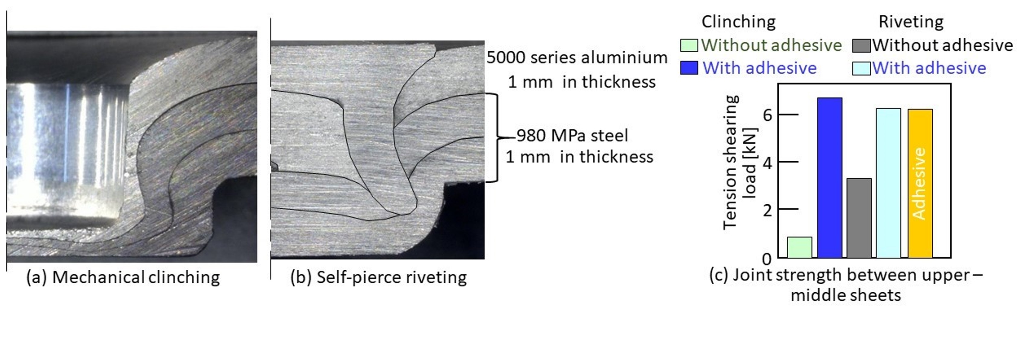
1. Introduction
2. Self-Pierce Riveting
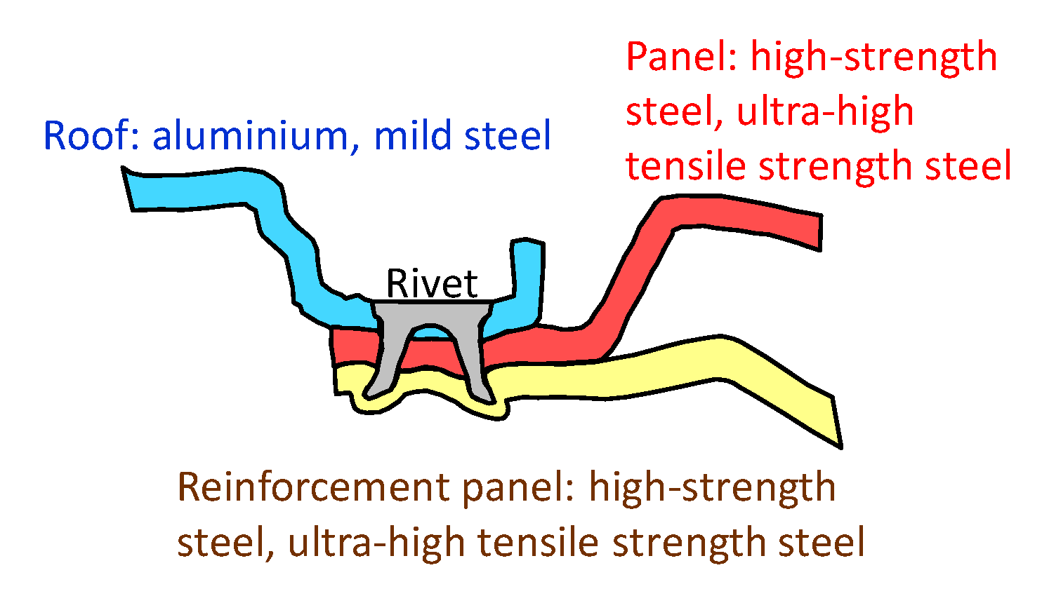
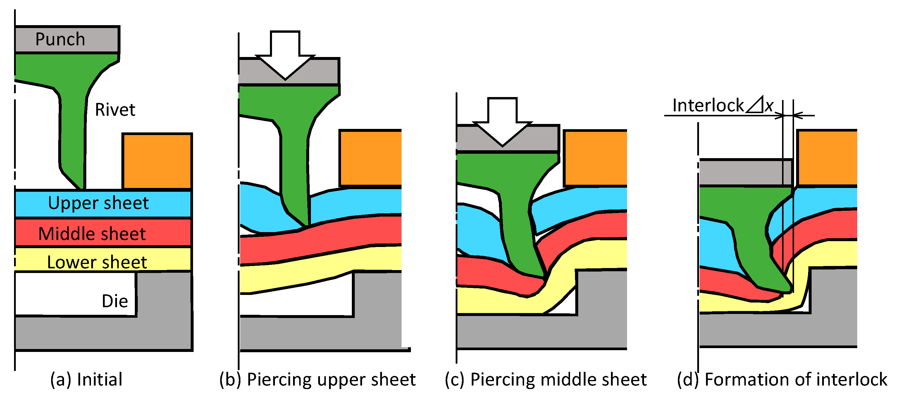
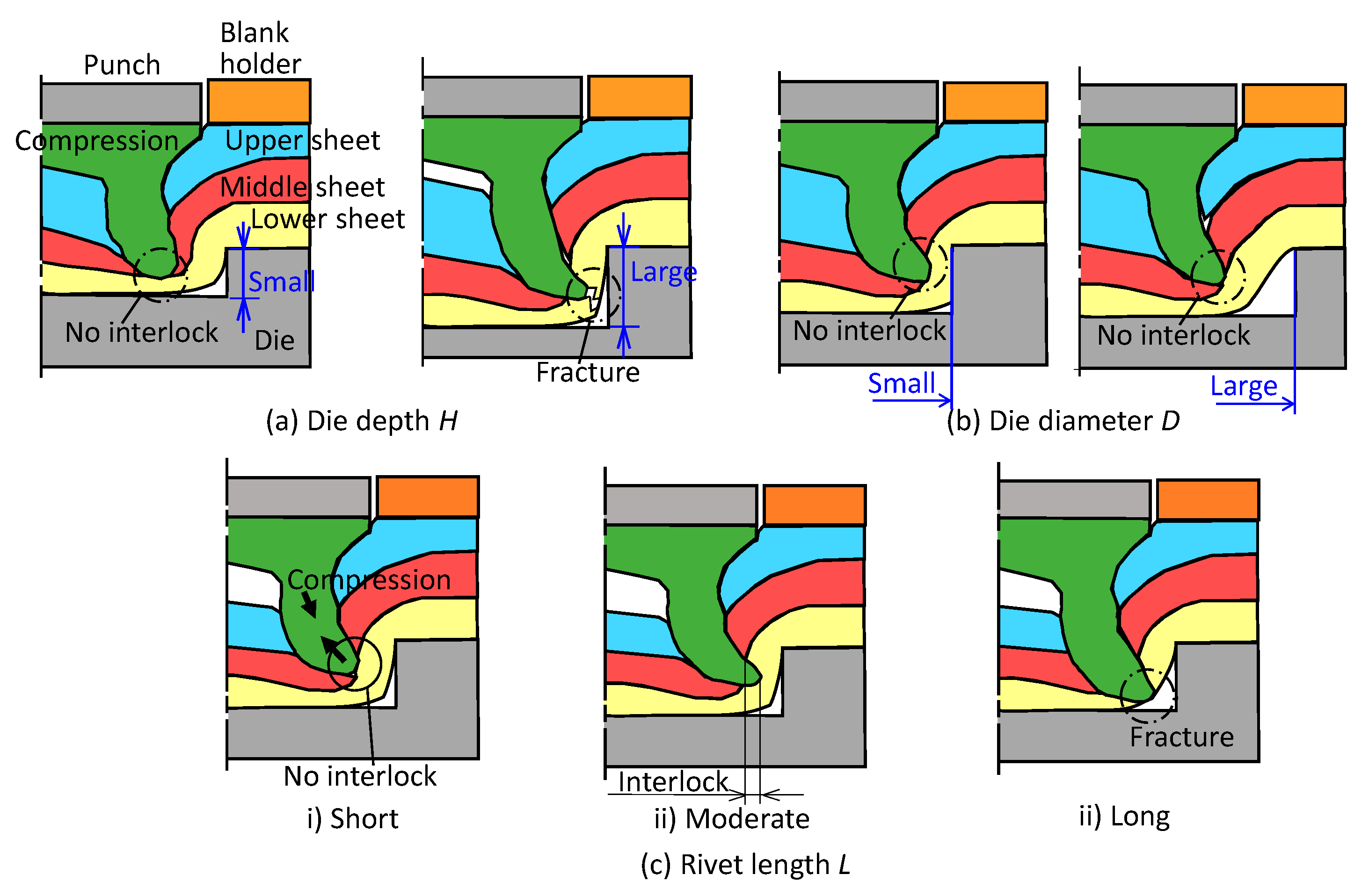
2.1. Self-Pierce Riveting Process of Three Sheets
- driving a rivet skirt through all sheets except for the lowest sheet;
- interlock formation by flaring rivet skirt in the lowest sheet;
- no fracturing of the lowest sheet.
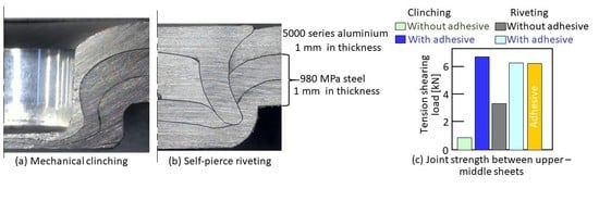
2.2. Sheet Materials
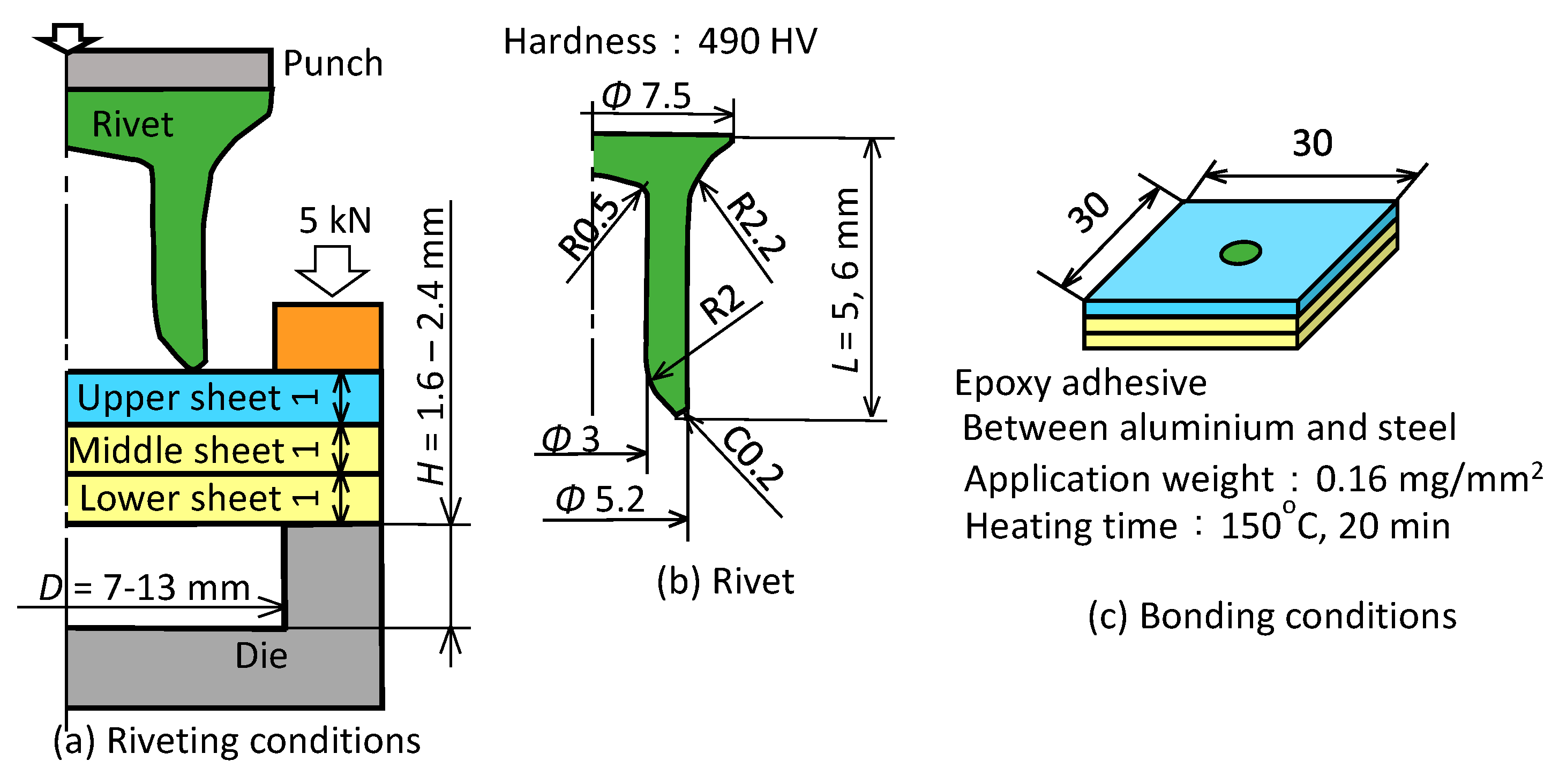
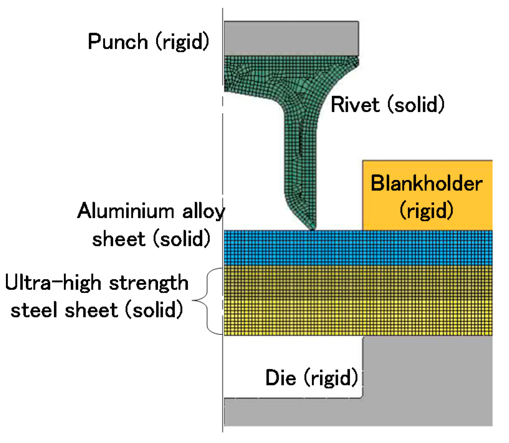
2.3. Experimental and Numerical Conditions of Self-Pierce Riveting
2.4. Upper Aluminium Alloy Sheet
2.5. Lower Aluminium Alloy Sheet
3. Mechanical Clinching
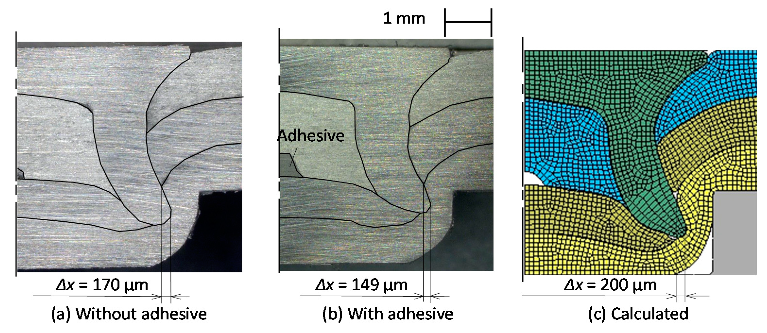
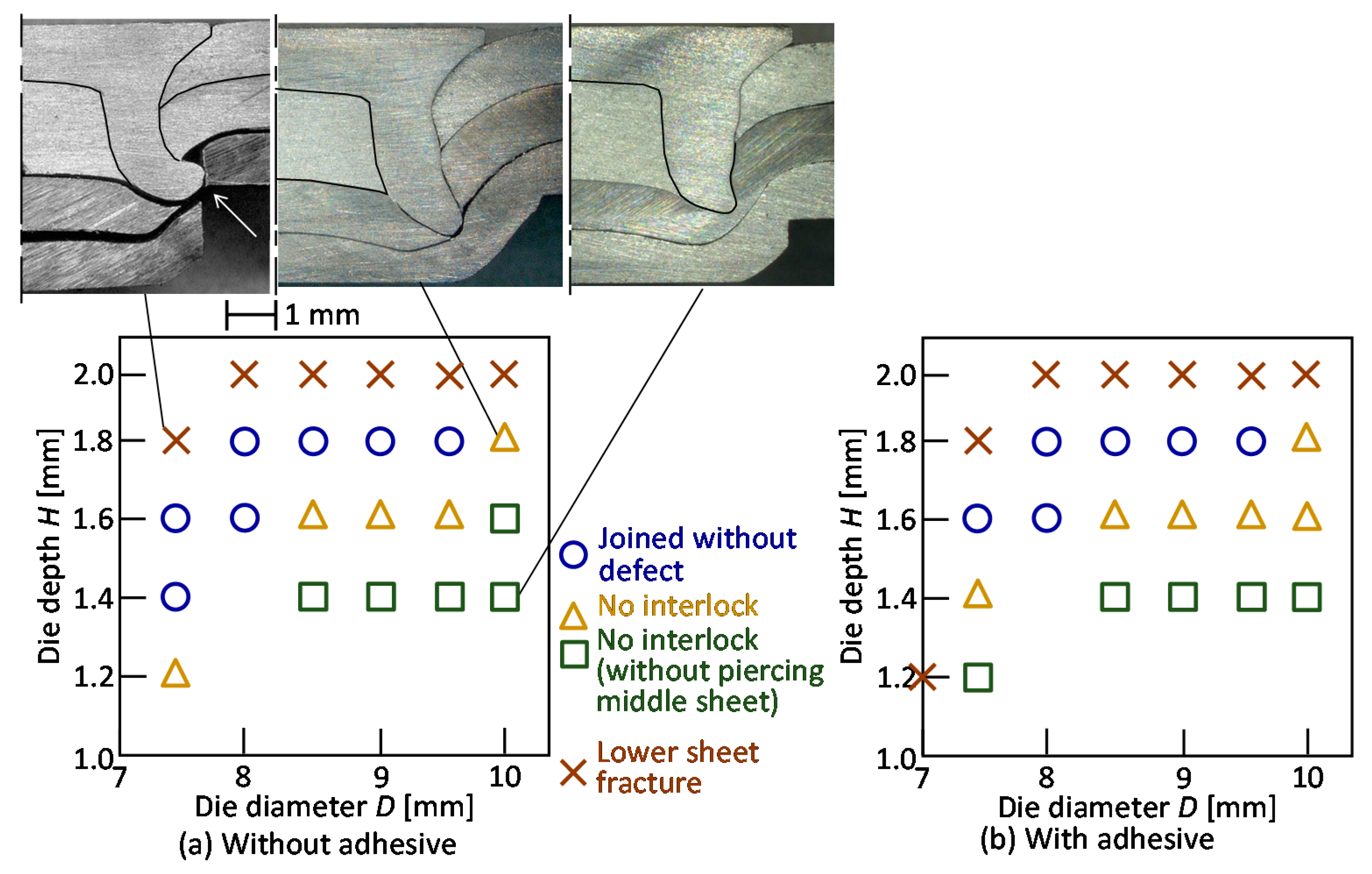
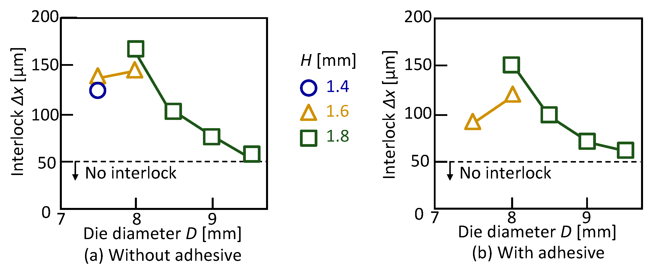
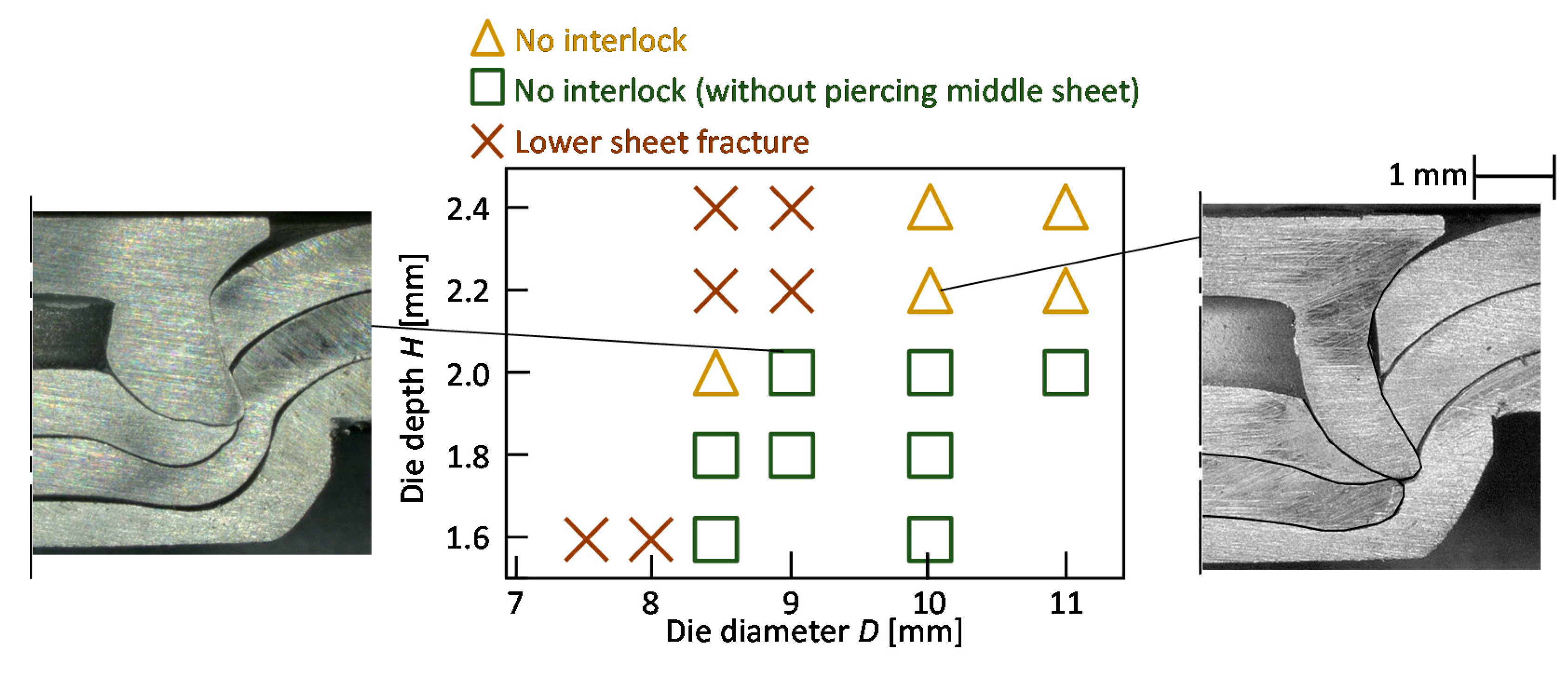
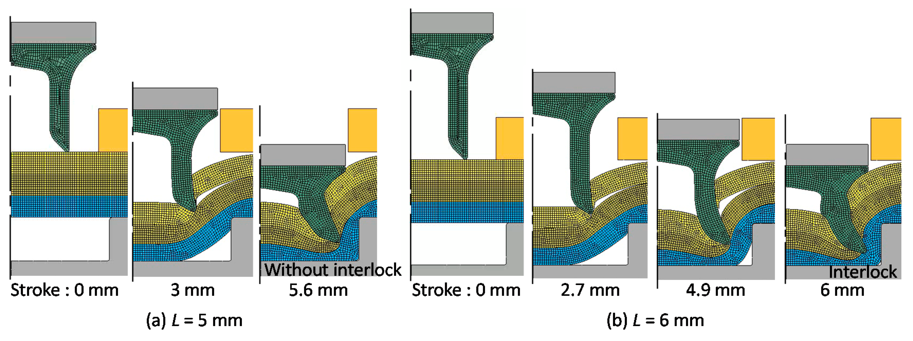
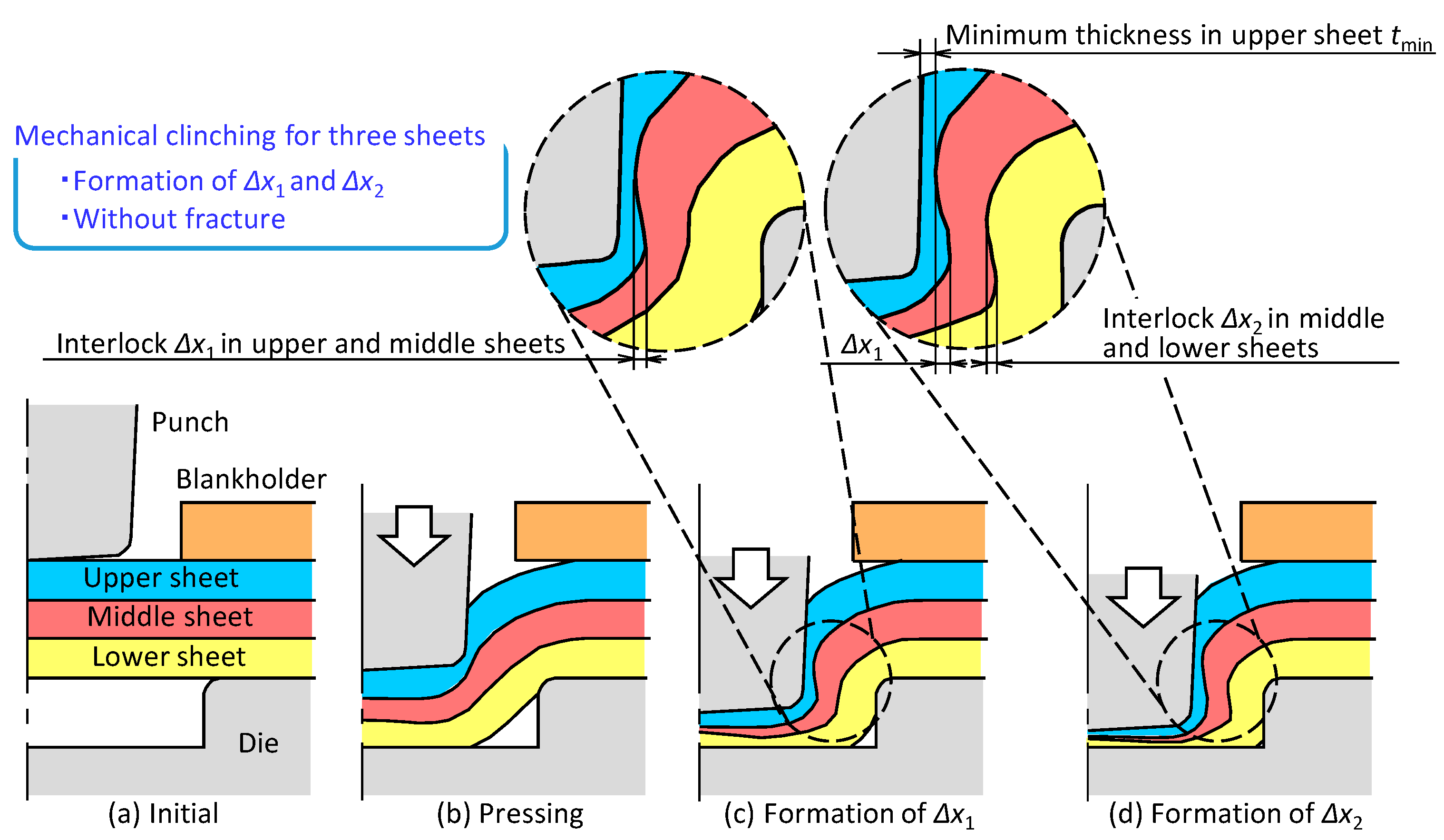
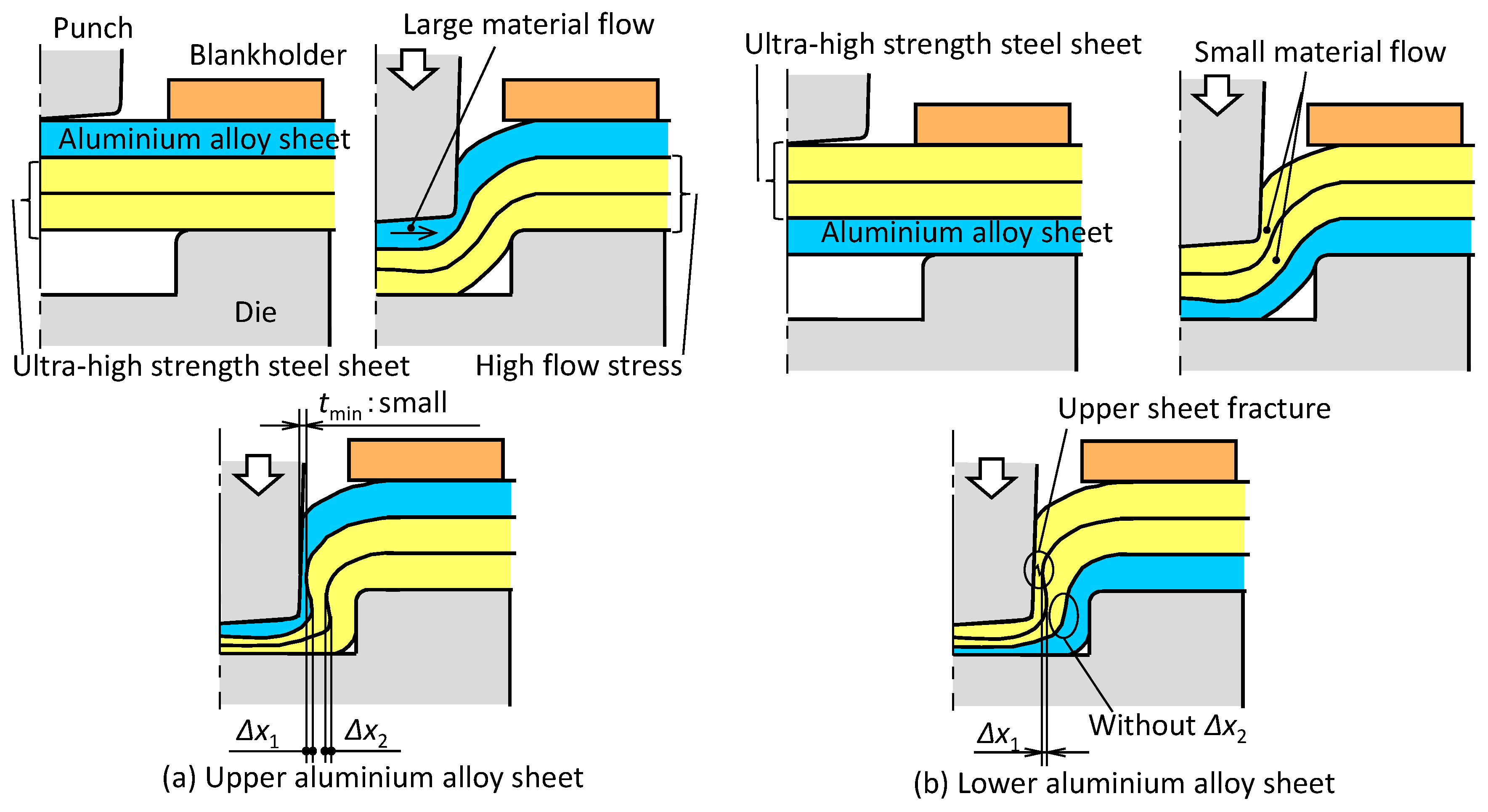
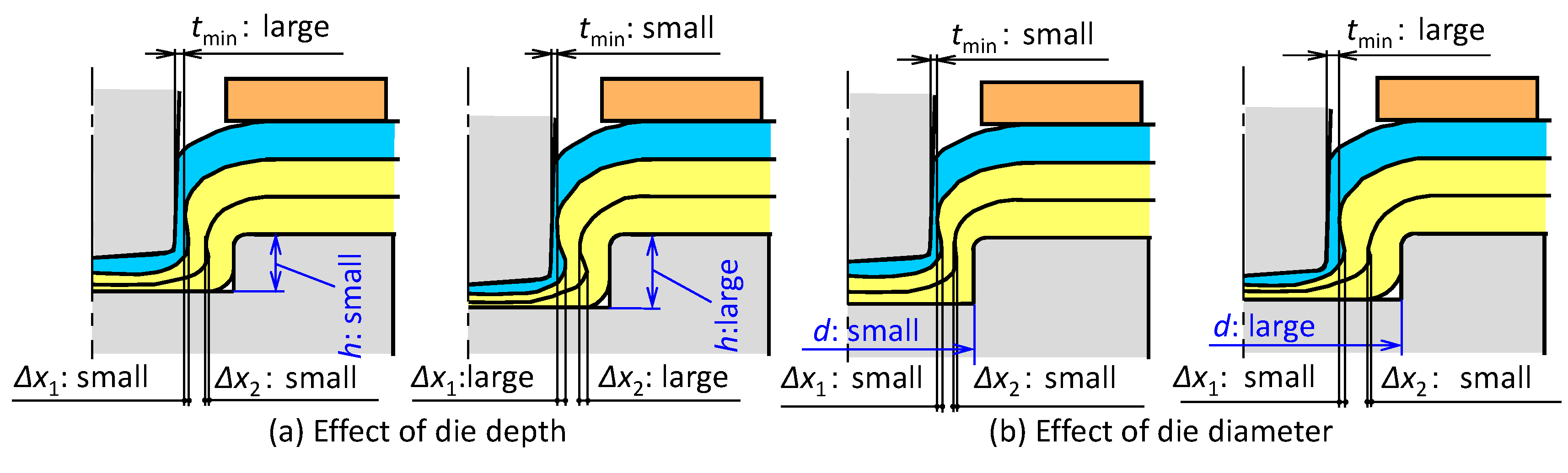
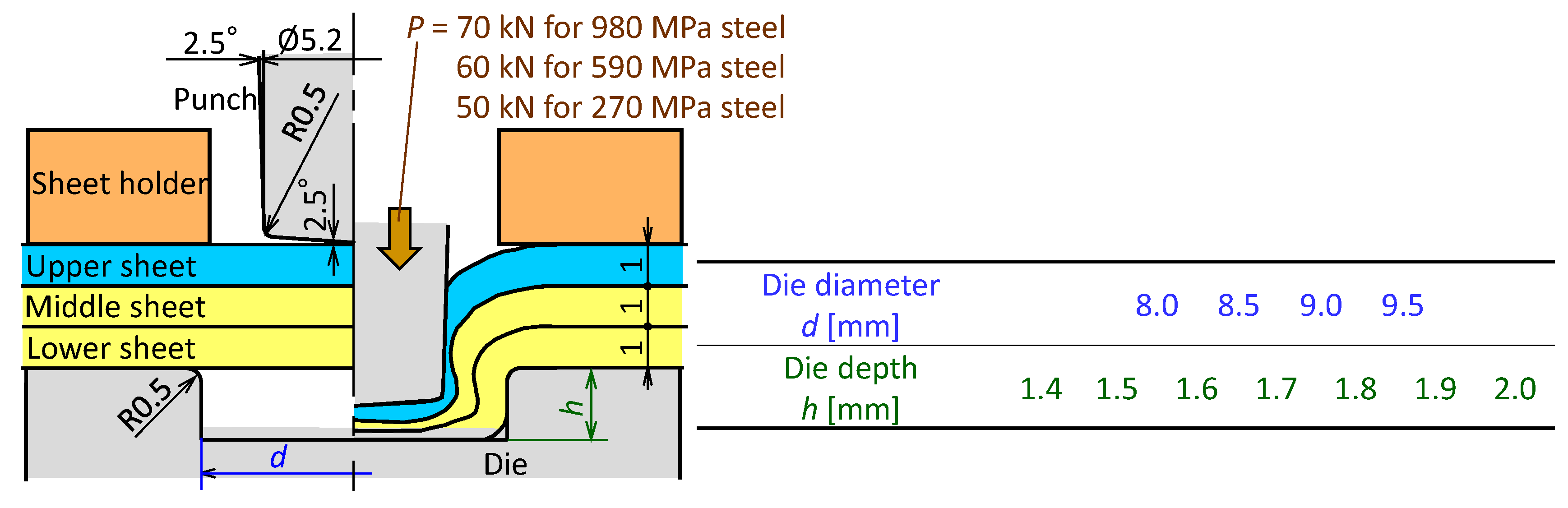
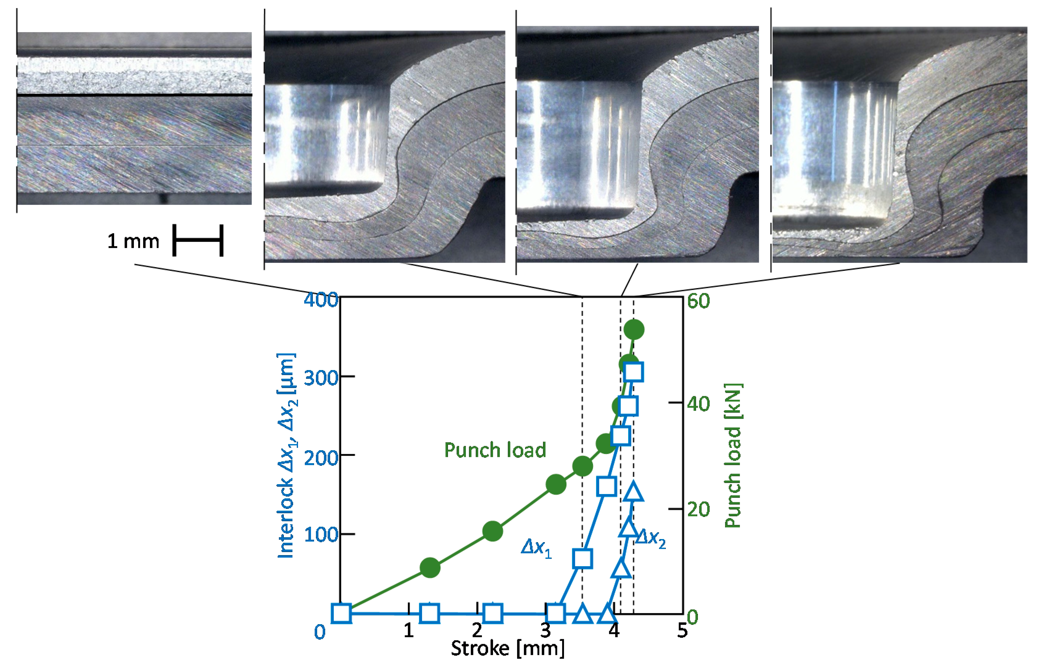
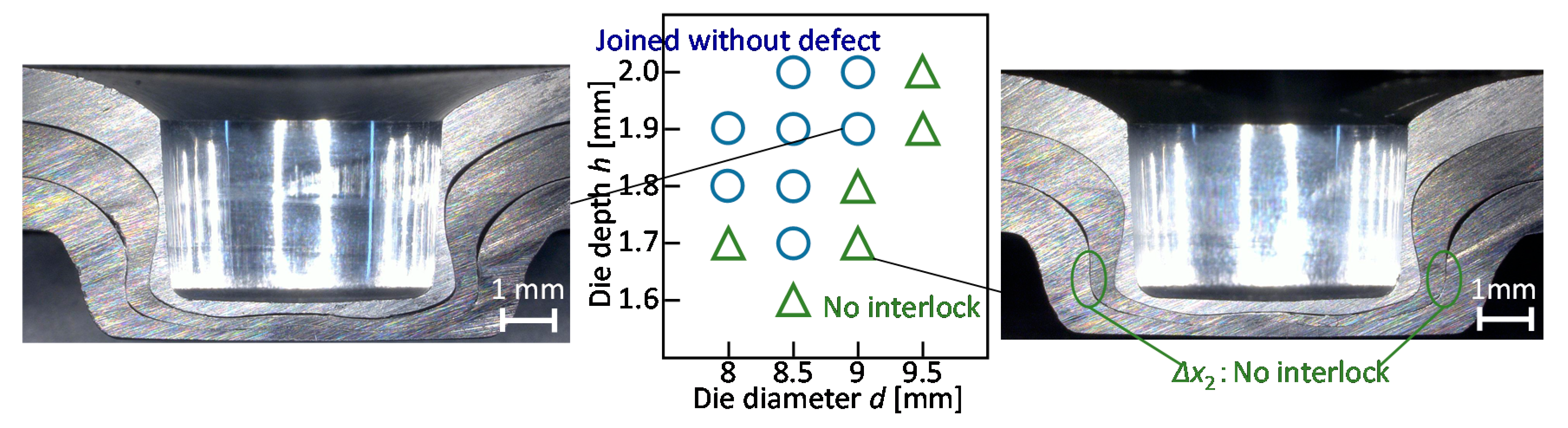
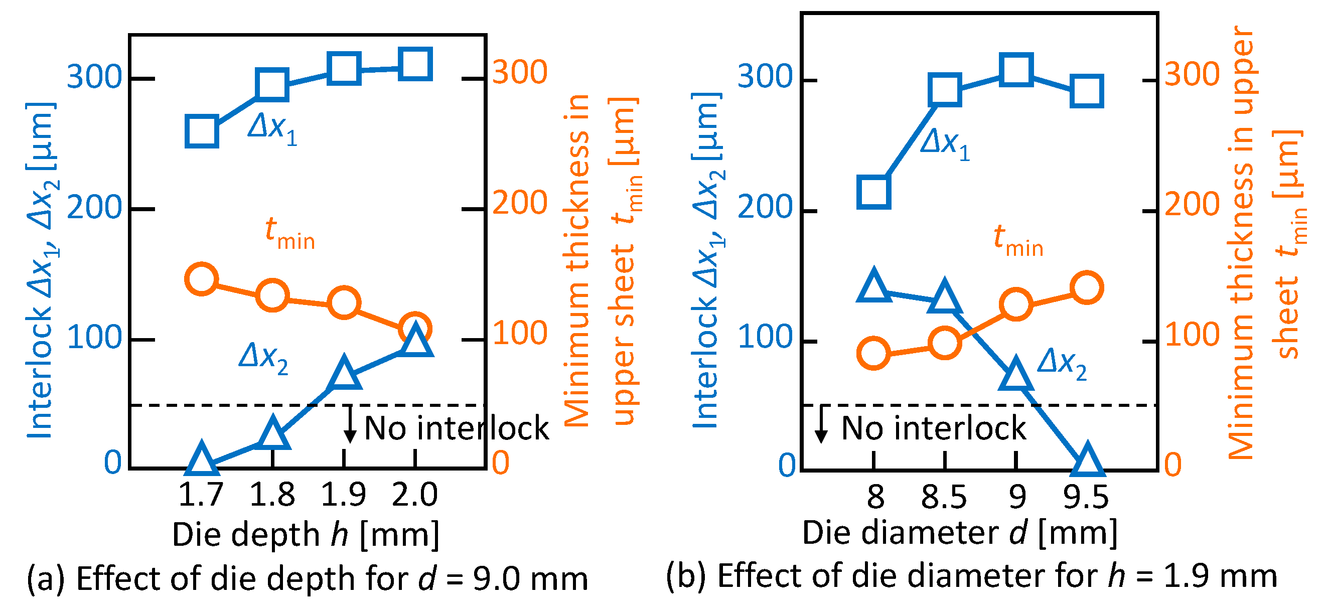
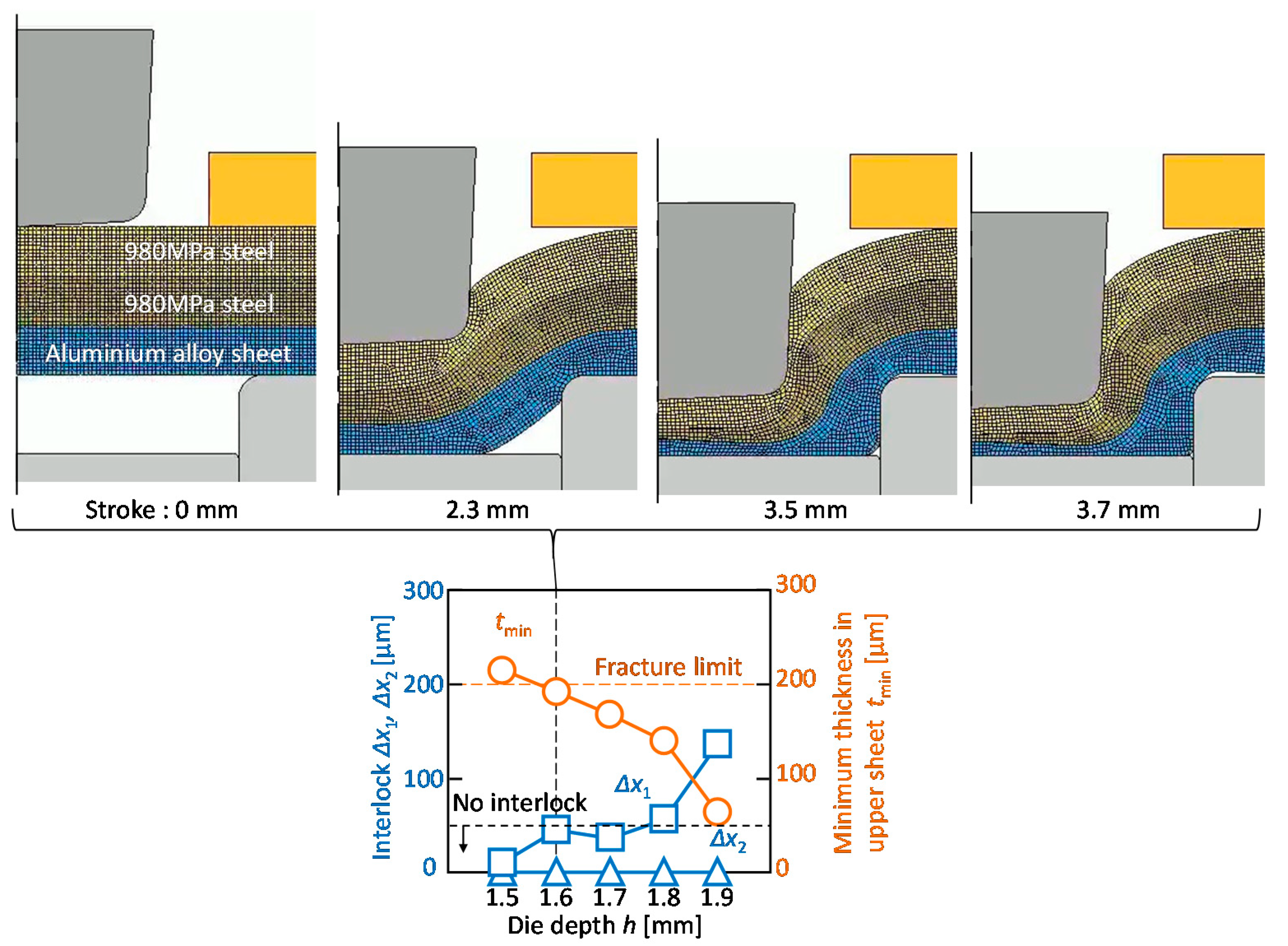
3.1. Mechanical Clinching Process of Three Sheets
- interlock formation between upper and middle sheets;
- interlock formation between middle and lower sheets;
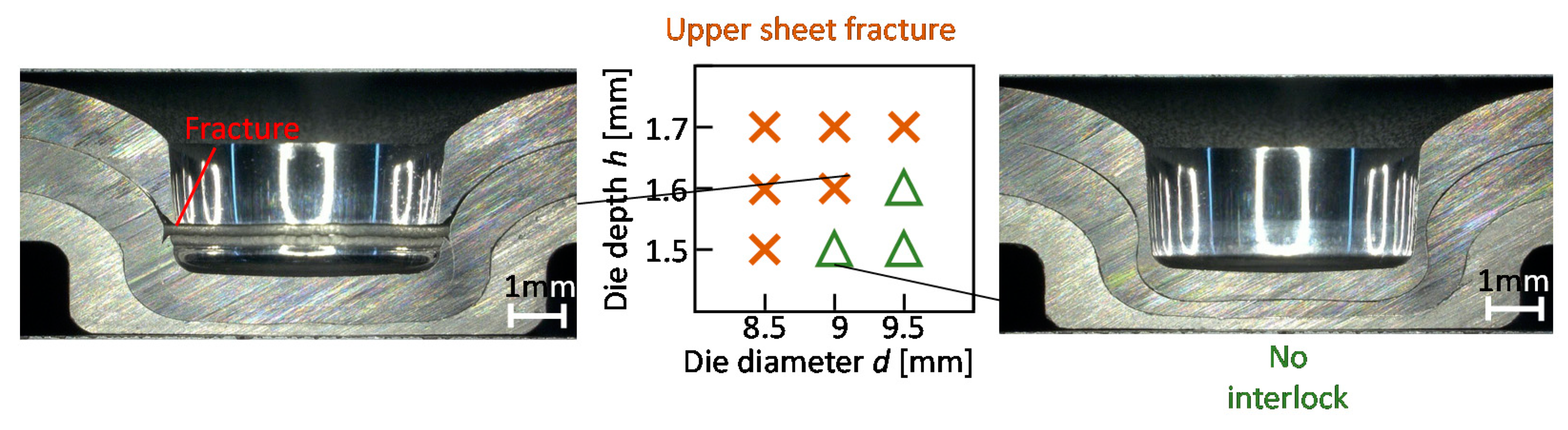
- no fracturing of sheets.
3.2. Conditions of Mechanical Clinching
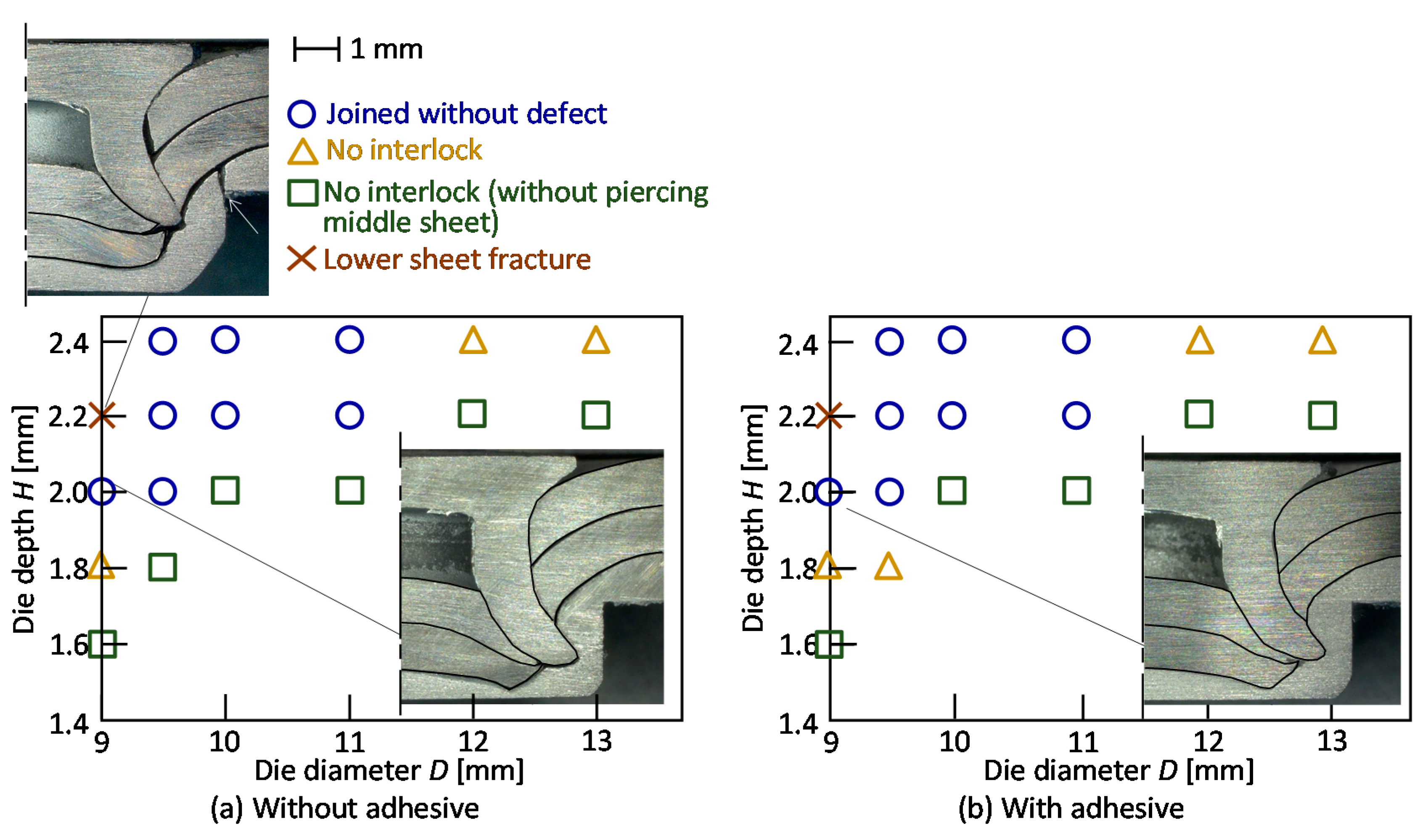
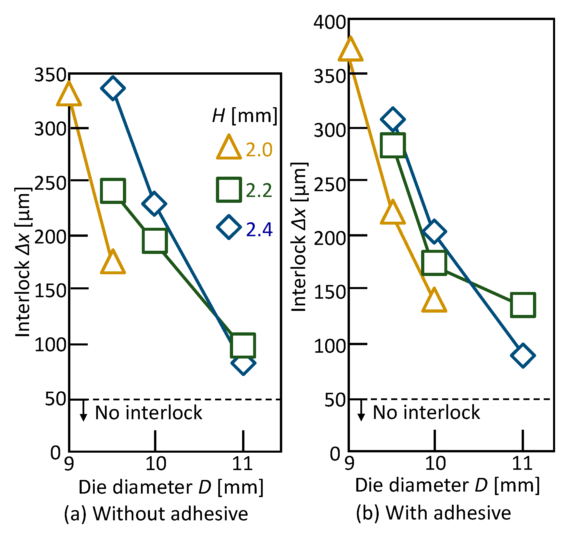
3.3. Upper Aluminium Alloy Sheet
3.4. Lower Aluminium Alloy Sheet
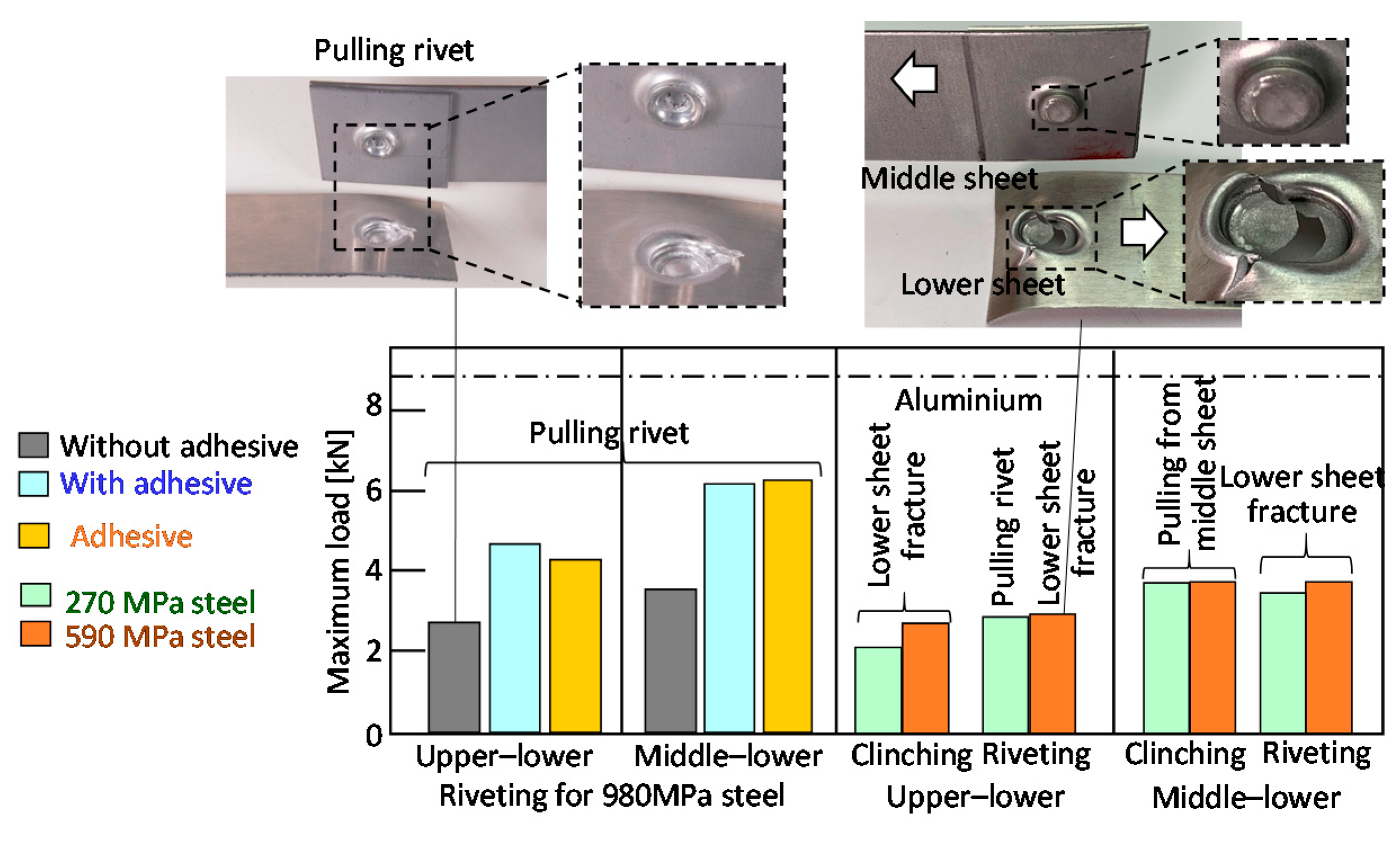
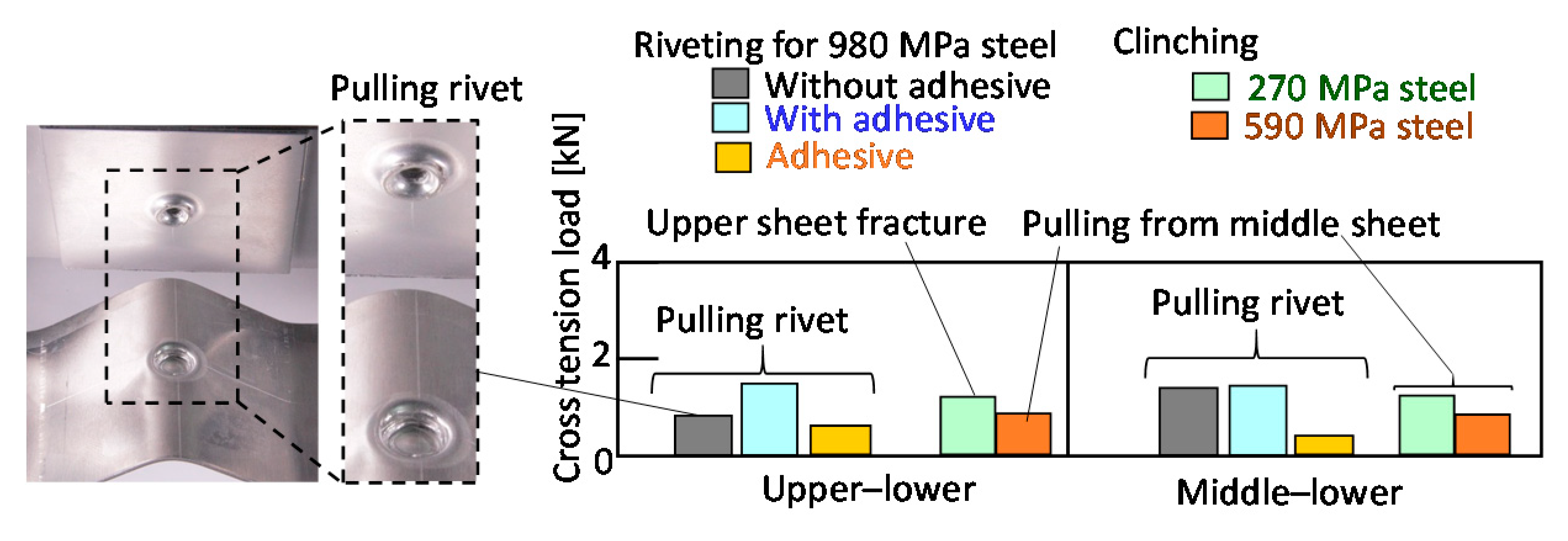
4. Joint Strength
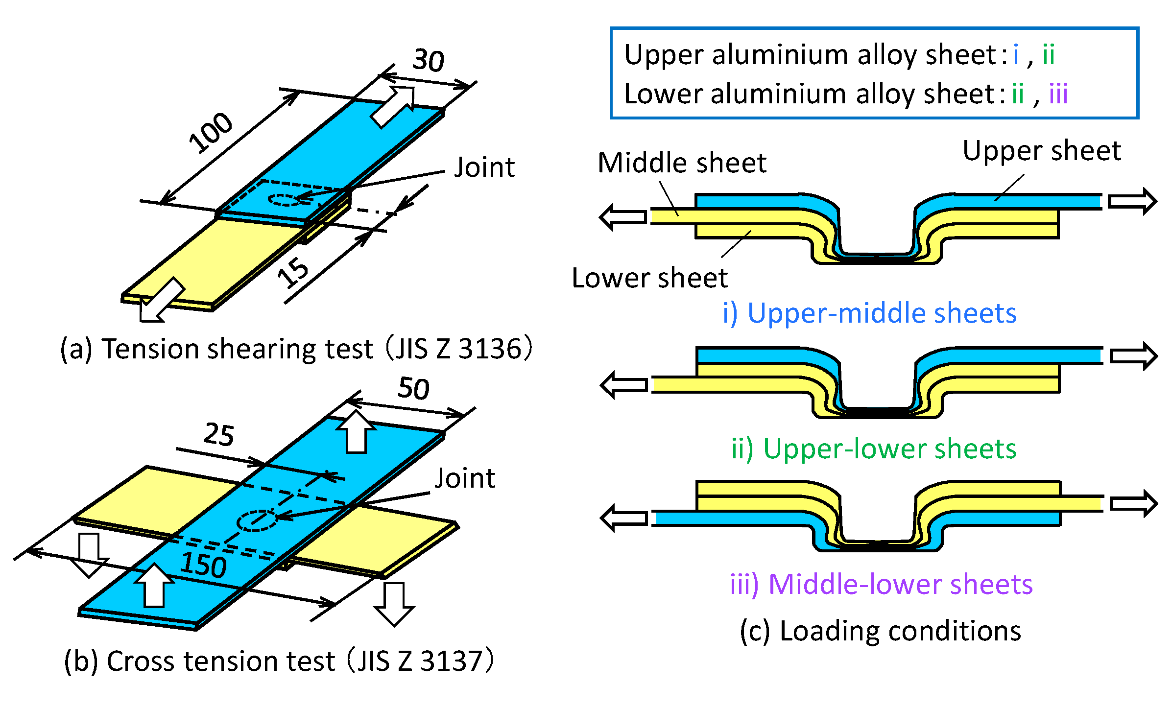
4.1. Measuring Conditions of Joint Strength
4.2. Upper Aluminium Alloy Sheet
4.3. Lower Aluminium Alloy Sheet
5. Conclusions
- 1
- The three sheets in both the sheet configurations were successfully joined by self-pierce riveting with the optimum die and rivet.
- 2
- The three sheets in the configuration of the upper aluminium alloy sheet were successfully joined by mechanical clinching with the optimum die, whereas the three sheets in the configuration of the lower aluminium alloy sheet were not joined with the modification of the die shape.
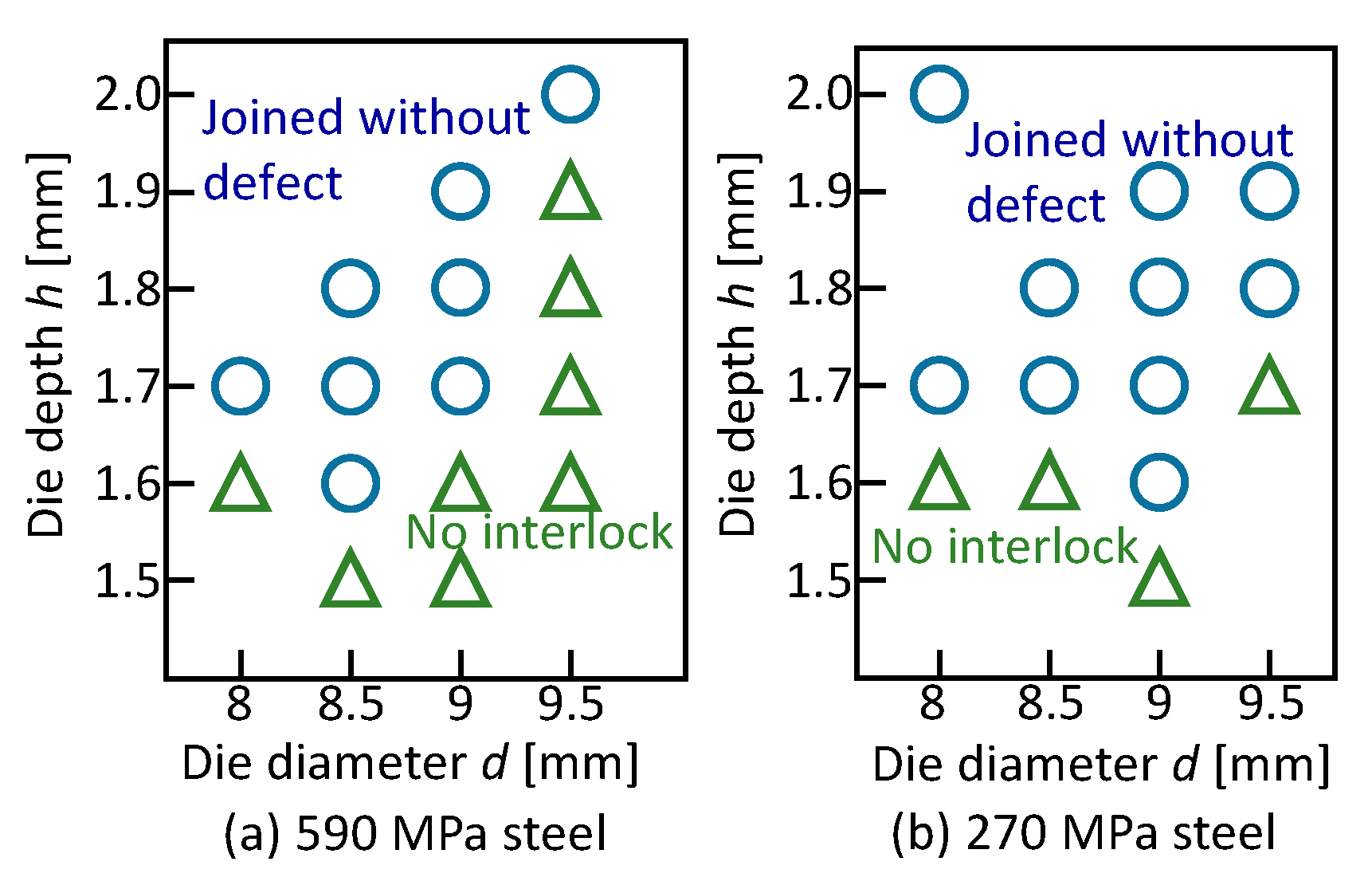
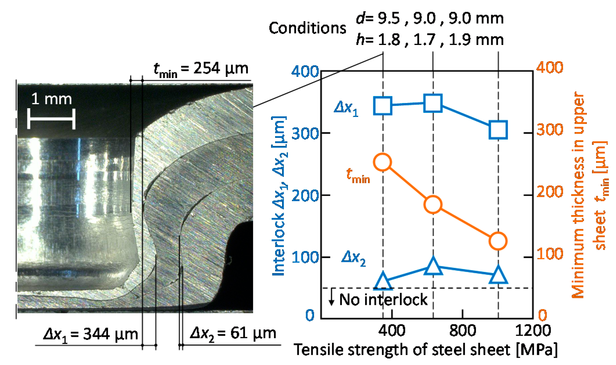
- 3
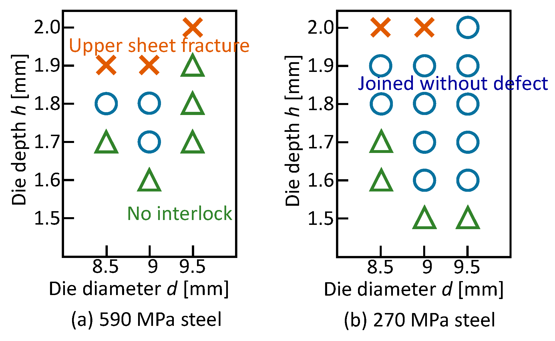
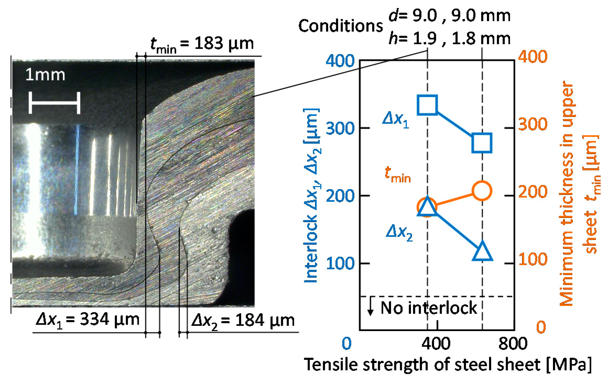
- In mechanical clinching in the configuration of the lower aluminium alloy sheet, the 590 MPa and 270 MPa steel sheets instead of the 980 MPa steel sheets were joined with the optimum die.
- 4
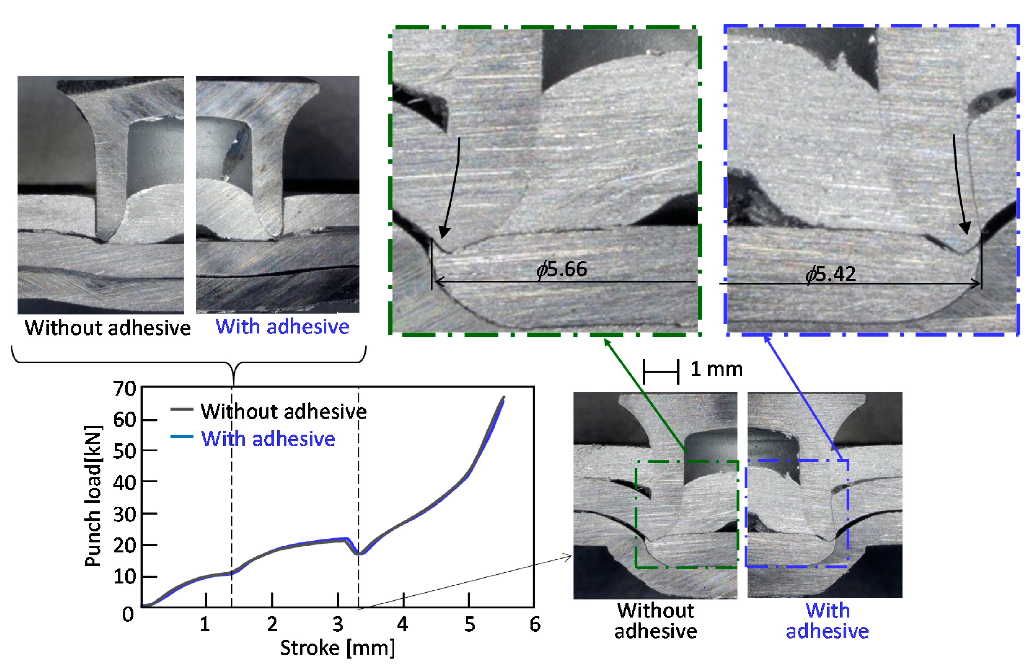
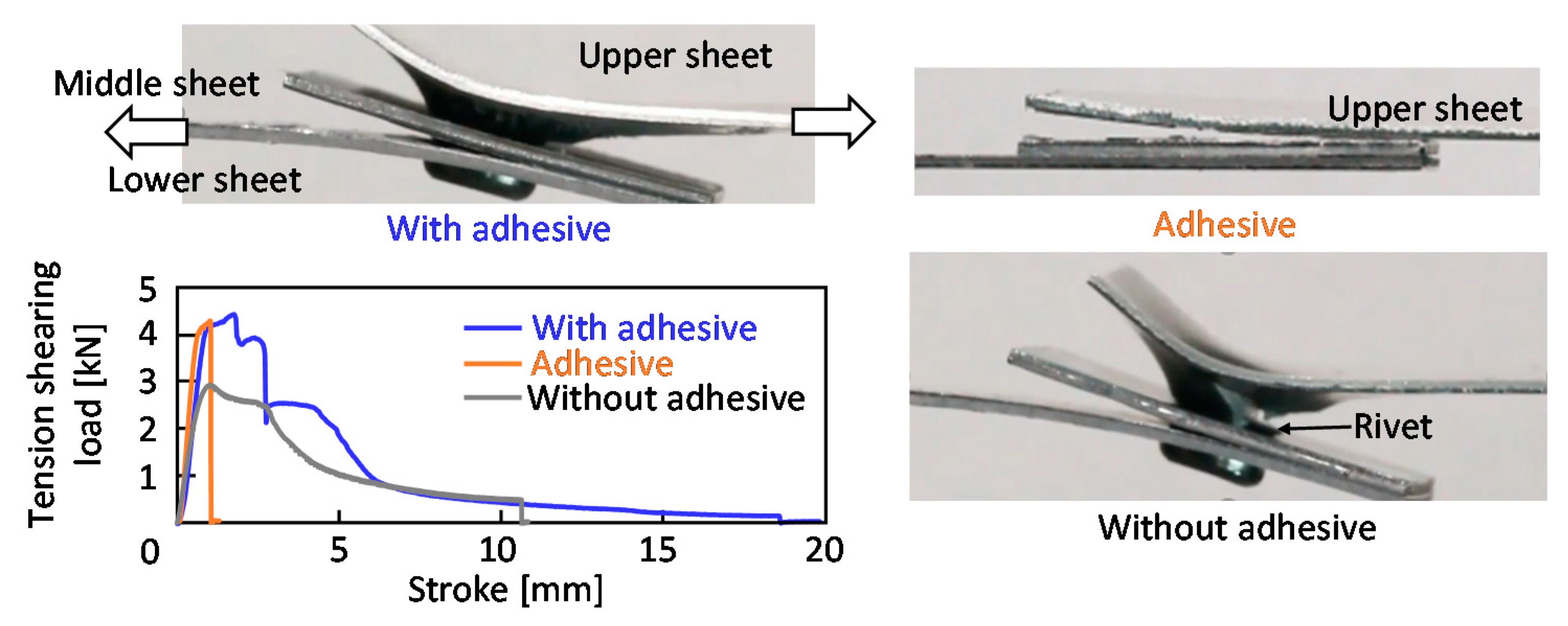
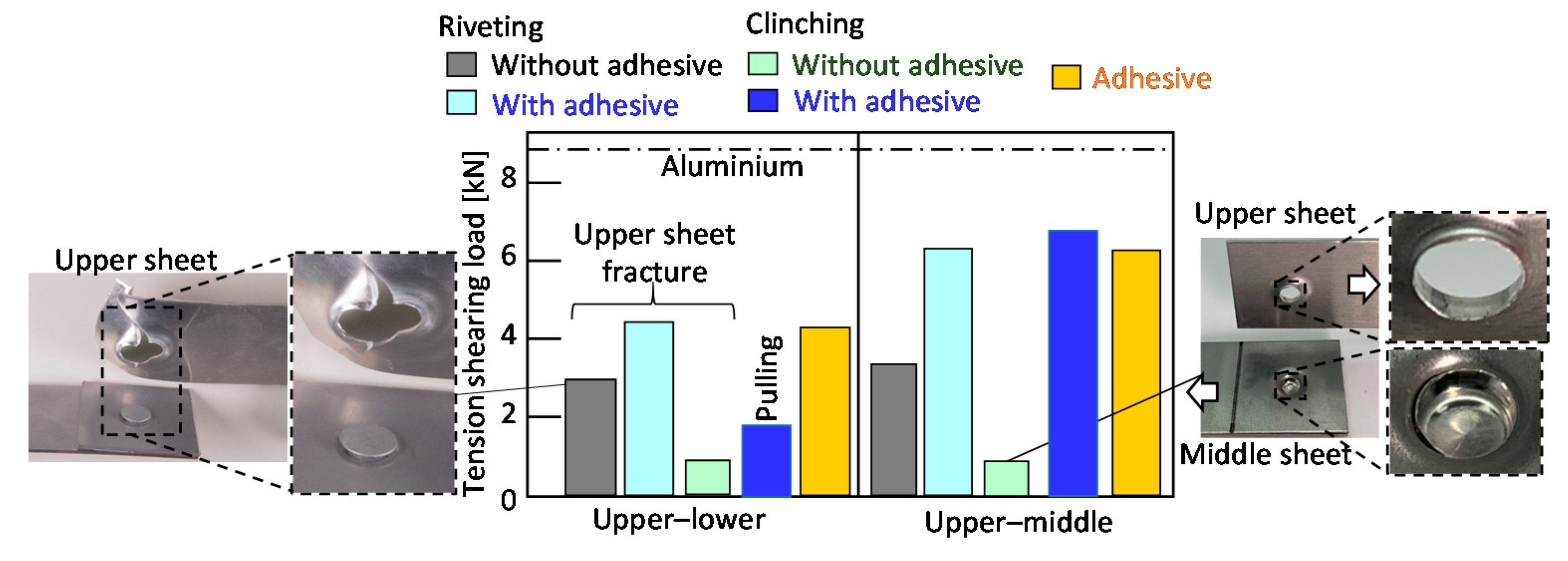
- Because the tension-shearing load of the adhesive was the highest, the loads of the clinched and riveted joints with the adhesive were similar to the loads of the adhesive.
- 5
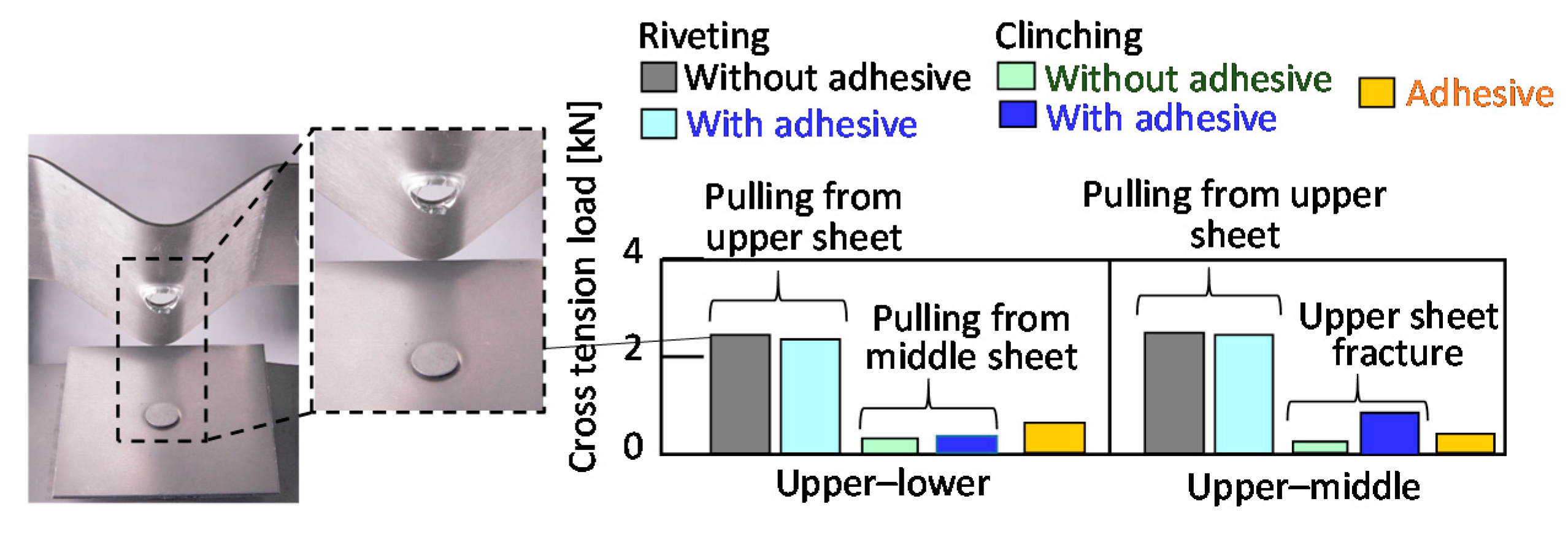
- Because the cross-tension load of the adhesive was small, the load increment of the joint with the adhesive was little.
Author Contributions
Funding
Conflicts of Interest
References
- Sakiyama, T.; Naito, Y.; Miyazaki, Y.; Nose, T.; Murayama, G.; Saita, K.; Oikawa, H. Dissimilar Metal Joining Technologies for Steel Sheet and Aluminum Alloy Sheet in Auto Body. Nippon Steel Tech. Rep. 2013, 103, 91–98. [Google Scholar]
- Meschut, G.; Janzen, V.; Olfermann, T. Innovative and Highly Productive Joining Technologies for Multi-Material Lightweight Car Body Structures. J. Mater. Eng. Perform. 2014, 23, 1515–1523. [Google Scholar] [CrossRef]
- He, X.; Pearson, I.; Young, K. Self-pierce riveting for sheet materials: State of the art. J. Mater. Process. Technol. 2008, 199, 27–36. [Google Scholar] [CrossRef]
- Barnes, T.; Pashby, I. Joining techniques for aluminium spaceframes used in automobiles. J. Mater. Process. Technol. 2000, 99, 72–79. [Google Scholar] [CrossRef]
- Porcaro, R.; Hanssen, A.; Langseth, M.; Aalberg, A. Self-piercing riveting process: An experimental and numerical investigation. J. Mater. Process. Technol. 2006, 171, 10–20. [Google Scholar] [CrossRef]
- Atzeni, E.; Ippolito, R.; Settineri, L. Experimental and numerical appraisal of self-piercing riveting. CIRP Ann. 2009, 58, 17–20. [Google Scholar] [CrossRef]
- Casalino, G.; Rotondo, A.; Ludovico, A. On the numerical modelling of the multiphysics self piercing riveting process based on the finite element technique. Adv. Eng. Softw. 2008, 39, 787–795. [Google Scholar] [CrossRef]
- Abe, Y.; Kato, T.; Mori, K. Joining of Aluminium Alloy Sheets by Aluminium Alloy Self-Piercing Rivet. In Proceedings of the 2nd International Conference on New Forming Technology, Bremen, Germany, 20–21 September 2007; pp. 451–460. [Google Scholar]
- Hoang, N.-H.; Porcaro, R.; Langseth, M.; Hanssen, A. Self-piercing riveting connections using aluminium rivets. Int. J. Solids Struct. 2010, 47, 427–439. [Google Scholar] [CrossRef] [Green Version]
- Karim, A.; Jeong, T.-E.; Noh, W.; Park, K.-Y.; Kam, D.-H.; Kim, C.; Nam, D.-G.; Jung, H.; Park, Y.-D. Joint quality of self-piercing riveting (SPR) and mechanical behavior under the frictional effect of various rivet coatings. J. Manuf. Process. 2020, 58, 466–477. [Google Scholar] [CrossRef]
- Cai, W.; Wang, P.; Yang, W. Assembly dimensional prediction for self-piercing riveted aluminum panels. Int. J. Mach. Tools Manuf. 2005, 45, 695–704. [Google Scholar] [CrossRef]
- Porcaro, R.; Hanssen, A.; Langseth, M.; Aalberg, A. The behaviour of a self-piercing riveted connection under quasi-static loading conditions. Int. J. Solids Struct. 2006, 43, 5110–5131. [Google Scholar] [CrossRef] [Green Version]
- Atzeni, E.; Ippolito, R.; Settineri, L. FEM Modeling of Self-Piercing Riveted Joint. Key Eng. Mater. 2007, 344, 655–662. [Google Scholar] [CrossRef]
- Wood, P.; Schley, C.A.; Williams, M.; Rusinek, A. A model to describe the high rate performance of self-piercing riveted joints in sheet aluminium. Mater. Des. 2011, 32, 2246–2259. [Google Scholar] [CrossRef]
- Abe, Y.; Kato, T.; Mori, K. Joinability of aluminium alloy and mild steel sheets by self piercing rivet. J. Mater. Process. Technol. 2006, 177, 417–421. [Google Scholar] [CrossRef]
- Han, L.; Chrysanthou, A. Evaluation of quality and behaviour of self-piercing riveted aluminium to high strength low alloy sheets with different surface coatings. Mater. Des. 2008, 29, 458–468. [Google Scholar] [CrossRef]
- Ma, Y.; Lou, M.; Li, Y.; Lin, Z. Effect of rivet and die on self-piercing rivetability of AA6061-T6 and mild steel CR4 of different gauges. J. Mater. Process. Technol. 2018, 251, 282–294. [Google Scholar] [CrossRef]
- Abe, Y.; Kato, T.; Mori, K. Self-piercing riveting of high tensile strength steel and aluminium alloy sheets using conventional rivet and die. J. Mater. Process. Technol. 2009, 209, 3914–3922. [Google Scholar] [CrossRef]
- Mori, K.; Kato, T.; Abe, Y.; Ravshanbek, Y. Plastic Joining of Ultra High Strength Steel and Aluminium Alloy Sheets by Self Piercing Rivet. CIRP Ann. 2006, 55, 283–286. [Google Scholar] [CrossRef]
- Uhe, B.; Kuball, C.-M.; Merklein, M.; Meschut, G. Improvement of a rivet geometry for the self-piercing riveting of high-strength steel and multi-material joints. Prod. Eng. 2020, 14, 417–423. [Google Scholar] [CrossRef]
- Bouchard, P.; Laurent, T.; Tollier, L. Numerical modeling of self-pierce riveting—From riveting process modeling down to structural analysis. J. Mater. Process. Technol. 2008, 202, 290–300. [Google Scholar] [CrossRef]
- Han, L.; Thornton, M.; Shergold, M. A comparison of the mechanical behaviour of self-piercing riveted and resistance spot welded aluminium sheets for the automotive industry. Mater. Des. 2010, 31, 1457–1467. [Google Scholar] [CrossRef] [Green Version]
- Sun, X.; Khaleel, M.A. Dynamic strength evaluations for self-piercing rivets and resistance spot welds joining similar and dissimilar metals. Int. J. Impact Eng. 2007, 34, 1668–1682. [Google Scholar] [CrossRef]
- Han, L.; Chrysanthou, A.; Young, K.W. Mechanical behaviour of self-piercing riveted multi-layer joints under different specimen configurations. Mater. Des. 2007, 28, 2024–2033. [Google Scholar] [CrossRef]
- Abe, Y.; Kato, T.; Mori, K.-I. Self-pierce riveting of three high strength steel and aluminium alloy sheets. Int. J. Mater. Form. 2008, 1, 1271–1274. [Google Scholar] [CrossRef]
- Mori, K.; Abe, Y.; Kato, T.; Sakai, S. Self-Pierce Riveting of Three Aluminium Alloy and Mild Steel Sheets. In AIP Conference Proceedings; AIP Publishing: College Park, MD, USA, 2010; Volume 1252, pp. 673–680. [Google Scholar]
- Peng, H.; Chen, C.; Zhang, H.; Ran, X. Recent development of improved clinching process. Int. J. Adv. Manuf. Technol. 2020, 110, 1–31. [Google Scholar] [CrossRef]
- Varis, J. Economics of clinched joint compared to riveted joint and example of applying calculations to a volume product. J. Mater. Process. Technol. 2006, 172, 130–138. [Google Scholar] [CrossRef]
- Lee, C.-J.; Kim, J.-Y.; Lee, S.-K.; Ko, D.-C.; Kim, B.-M. Design of mechanical clinching tools for joining of aluminium alloy sheets. Mater. Des. 2010, 31, 1854–1861. [Google Scholar] [CrossRef]
- Mizushima, D.; Murakami, H. Effect of Lubricant Viscosity on Peeling Strength of Mechanical Clinching. J. Jpn. Soc. Technol. Plast. 2010, 51, 974–978. [Google Scholar] [CrossRef]
- Varis, J. The suitability of clinching as a joining method for high-strength structural steel. J. Mater. Process. Technol. 2003, 132, 242–249. [Google Scholar] [CrossRef]
- Varis, J. The suitability of round clinching tools for high strength structural steel. Thin-Walled Struct. 2002, 40, 225–238. [Google Scholar] [CrossRef]
- Chen, L.-W.; Huang, J.-M.; Hsu, Y.-C. Investigation of the clinching process combines with hot stamping process for high-strength steel sheets. MATEC Web Conf. 2015, 21, 05004. [Google Scholar] [CrossRef]
- Chen, L.-W.; Cai, M.-J. Development of a hot stamping clinching tool. J. Manuf. Process. 2018, 34, 650–658. [Google Scholar] [CrossRef]
- Abe, Y.; Kishimoto, M.; Kato, T.; Mori, K.-I. Mechanical Clinching of Hot-Dip Zinc-Aluminum Alloy Coated Steel Sheets. J. Jpn. Soc. Technol. Plast. 2010, 51, 592–596. [Google Scholar] [CrossRef]
- Behrens, B.-A.; Bouguecha, A.; Vučetić, M.; Hübner, S.; Yilkiran, D.; Jin, Y.; Peshekhodov, I. FEA-based optimisation of a clinching process with an open multiple-part die aimed at damage minimisation in CR240BH-AlSi10MnMg joints. MATEC Web Conf. 2015, 21, 04009. [Google Scholar] [CrossRef]
- Abe, Y.; Mori, K.; Kato, T. Joining of high strength steel and aluminium alloy sheets by mechanical clinching with dies for control of metal flow. J. Mater. Process. Technol. 2012, 212, 884–889. [Google Scholar] [CrossRef]
- Abe, Y.; Mori, K. Mechanical Clinching Process with Preforming of Lower Sheet for Joining Aluminium and Ultra-High Strength Steel Sheets. Quart. J. Jpn. Weld. Soc. 2020, 38, 89s–92s. [Google Scholar]
- Wiesenmayer, S.; Han, D.; Meschut, G.; Merklein, M. Investigation of the tool wear behaviour in shear-clinching processes during the running-in phase. In Proceedings of the 22nd International Esaform Conference on Material Forming: Esaform 2019, Vitoria-Gasteiz, Spain, 8–10 May 2019; p. 050005. [Google Scholar] [CrossRef]
- Busse, S.; Merklein, M.; Roll, K.; Ruther, M.; Zürn, M. Development of a mechanical joining process for automotive body-in-white production. Int. J. Mater. Form. 2010, 3, 1059–1062. [Google Scholar] [CrossRef]
- Lee, C.-J.; Lee, S.-H.; Lee, J.-M.; Kim, B.-H.; Kim, B.-M.; Ko, D.-C. Design of hole-clinching process for joining CFRP and aluminum alloy sheet. Int. J. Precis. Eng. Manuf. 2014, 15, 1151–1157. [Google Scholar] [CrossRef]
- Lambiase, F.; Ko, D.-C. Feasibility of mechanical clinching for joining aluminum AA6082-T6 and Carbon Fiber Reinforced Polymer sheets. Mater. Des. 2016, 107, 341–352. [Google Scholar] [CrossRef]
- Kaðèák, L.; Spiðák, E.; Kubík, R.; Mucha, J. Finite Element Calculation of Clinching with Rigid Die of Three Steel Sheets. Strength Mater. 2017, 49, 488–499. [Google Scholar] [CrossRef]
- Kaščák, L.; Spišák, E.; Majerníková, J. Joining three car body steel sheets by clinching method. Open Eng. 2016, 6, 566–573. [Google Scholar] [CrossRef]
- Moroni, F. Fatigue behaviour of hybrid clinch-bonded and self-piercing rivet bonded joints. J. Adhes. 2018, 95, 577–594. [Google Scholar] [CrossRef]
- Neugebauer, R.; Israel, M.; Mayer, B.; Fricke, H. Numerical and Experimental Studies on the Clinch-Bonding and Riv-Bonding Process. Key Eng. Mater. 2012, 771–776. [Google Scholar] [CrossRef]
- Japanese Industrial Standards. Specimen Dimensions and Procedure for Shear Testing Resistance Spot and Embossed Projection Welds, 1999, JIS Z3136. Available online: https://www.jisc.go.jp/app/jis/general/GnrJISNumberNameSearchList?show (accessed on 20 October 2020). (In Japanese)
- Japanese Industrial Standards. Specimen Dimensions and Procedure for Cross Tension Testing Resistance Spot and Embossed Projection Welds, 1999, JIS Z3137. Available online: https://www.jisc.go.jp/app/jis/general/GnrJISNumberNameSearchList?toGnrJISStandardDetailList (accessed on 20 October 2020). (In Japanese)


| Sheet | Sheet Thickness (mm) | Tensile Strength (MPa) | Elongation (%) | Reduction in Area (%) |
|---|---|---|---|---|
| 5000 series aluminium alloy | 1.05 | 275 | 25 | 65 |
| 980 MPa steel | 1.05 | 1002 | 14 | 35 |
Publisher’s Note: MDPI stays neutral with regard to jurisdictional claims in published maps and institutional affiliations. |
© 2020 by the authors. Licensee MDPI, Basel, Switzerland. This article is an open access article distributed under the terms and conditions of the Creative Commons Attribution (CC BY) license (http://creativecommons.org/licenses/by/4.0/).
Share and Cite
Abe, Y.; Maeda, T.; Yoshioka, D.; Mori, K.-i. Mechanical Clinching and Self-Pierce Riveting of Thin Three Sheets of 5000 Series Aluminium Alloy and 980 MPa Grade Cold Rolled Ultra-High Strength Steel. Materials 2020, 13, 4741. https://doi.org/10.3390/ma13214741
Abe Y, Maeda T, Yoshioka D, Mori K-i. Mechanical Clinching and Self-Pierce Riveting of Thin Three Sheets of 5000 Series Aluminium Alloy and 980 MPa Grade Cold Rolled Ultra-High Strength Steel. Materials. 2020; 13(21):4741. https://doi.org/10.3390/ma13214741
Chicago/Turabian StyleAbe, Yohei, Takato Maeda, Daiki Yoshioka, and Ken-ichiro Mori. 2020. "Mechanical Clinching and Self-Pierce Riveting of Thin Three Sheets of 5000 Series Aluminium Alloy and 980 MPa Grade Cold Rolled Ultra-High Strength Steel" Materials 13, no. 21: 4741. https://doi.org/10.3390/ma13214741