Galvanically Stimulated Degradation of Carbon-Fiber Reinforced Polymer Composites: A Critical Review


1
Department of Materials and Ceramic Engineering, CICECO-Aveiro Institute of Materials, University of Aveiro, Campus Universitário de Santiago, 3810-193 Aveiro, Portugal
2
MagIC, Institute of Materials Research, Helmholtz-Zentrum Geesthacht, Max-Planck-Strasse 1, 21502 Geesthacht, Germany
3
Institute for Materials Science, Faculty of Engineering, Kiel University, 24103 Kiel, Germany
*
Author to whom correspondence should be addressed.
Materials 2019, 12(4), 651; https://doi.org/10.3390/ma12040651
Submission received: 24 November 2018
/
Revised: 30 January 2019
/
Accepted: 13 February 2019
/
Published: 21 February 2019
(This article belongs to the Section Corrosion)
Abstract
:Carbon is used as a reinforcing phase in carbon-fiber reinforced polymer composites employed in aeronautical and other technological applications. Under polarization in aqueous media, which can occur on galvanic coupling of carbon-fiber reinforced polymers (CFRP) with metals in multi-material structures, degradation of the composite occurs. These degradative processes are intimately linked with the electrically conductive nature and surface chemistry of carbon. This review highlights the potential corrosion challenges in multi-material combinations containing carbon-fiber reinforced polymers, the surface chemistry of carbon, its plausible effects on the electrochemical activity of carbon, and consequently the degradation processes on carbon-fiber reinforced polymers. The implications of the emerging use of conductive nano-fillers (carbon nanotubes and carbon nanofibers) in the modification of CFRPs on galvanically stimulated degradation of CFRP is accentuated. The problem of galvanic coupling of CFRP with selected metals is set into perspective, and insights on potential methods for mitigation and monitoring the degradative processes in these composites are highlighted.
Keywords:
carbon fiber; polymer matrix; metals; multi-material; interface; cathodic; galvanic coupling; high pH; degradation
1. Introduction
Besides their predominant usage in the transport industry, carbon-fiber reinforced polymers (CFRPs) are employed in other technological applications in a wide variety of industries [1]. In the medical industry, they used in such applications as fracture fixation devices and orthopedic implants [2,3,4,5,6,7,8,9,10,11,12,13,14,15,16]. In the construction and civil engineering industry, CFRP is used as a structural member in construction and for retrofitting and repairing structural deficiencies in infrastructures such as bridges and buildings caused by age, corrosion, mis-use, and/or seismic disturbances [17,18,19,20,21,22,23,24,25,26,27,28,29,30,31,32,33,34,35]. CFRP is also used as an electromagnetic interference shield [36,37,38], electric discharge, and lightening strike protection on modifications to enhance electrical conductivity [39], sports products [40], in the maritime industry in boats, ships, and submarines [41,42,43,44], and as a corrosion resistant and reinforcing liner in pipes. In the offshore oil and gas industry it is used in the repair of corroded and mechanically-damaged onshore pipelines in which the predominant load is internal pressure [45,46,47,48,49,50,51]. In addition to good strength-to-weight ratios of CFRP’s, a potential for self-healing (i.e., recovery of mechanical and other properties post damage) has been demonstrated [52,53].
Besides its use in the applications above, CFRP has the potential to become a multi-functional material capable of being deployed for simultaneous structural and sensing applications. This outlook is based on the multiple reports of the sensing ability of CFRP electrodes for a wide variety of compounds. Carbon–polyvinylchloride (C–PVC) composite electrode has been reported [54] to detect dopamine, ascorbic acid, uric acid, and their mixtures. Thostenson and Chou [55,56] have demonstrated real-time in-situ sensing of the onset, nature, and evolution of damage in advanced fiber reinforced composites with an epoxy matrix.
An interesting development and emerging application that could consolidate, and greatly increase the consumption and wider usage of CFRP is its processing by additive manufacturing. Additive manufacturing can enable easier processing of stronger products with better weight optimization and highly orientated properties guided by information on anticipated load conditions [57,58,59,60,61,62,63,64,65]. Recent reports [60,61,62,63,64,65] of successful 3D printing and additive manufacturing of CFRP parts are capable of tilting the economics of weight-to-strength optimization strategies using CFRP, encouraging its use in more applications due to reduced costs and greater ease in its processing that can allow low production volumes of parts with more intricate geometrical complexities that precludes their production with current CFRP manufacturing methods. On the strength of our evaluation of the current use and applications of CFRP, the regulatory environment (both external and internal) for reduction of CO2 emission in the transport industry, and the current and emerging technologies for CFRP processing, a rapid increase in CFRP consumption and its adoption in a wider range of applications is projected. This will be due to a favorable regulatory environment and emerging manufacturing processes (3D printing and/or additive manufacturing) that is very likely to significantly lower production costs while enabling the production of more intricate parts at lower production volumes.
In most of its technological applications CFRPs are used as component(s) of hybrid structures. Multi-material combinations containing CFRPs, which are common in weight-optimized structures used in the aeronautical and other transport industries, are seeing progressive increases in the percentage of CFRP employed in these multi-material structures and in the number of the other constituent materials [66,67,68,69,70,71,72,73,74,75,76,77,78,79,80,81,82]. Hybrid structures consisting of CFRPs can emerge in the joining of CFRP with other materials such as in the adhesive attachment of fiber-reinforced polymers (FRP) laminates to the external face of reinforced concrete structures while retrofitting and strengthening concrete structures [83], in joining of CFRP laminates to metals where galvanic coupling can occur due to failure of insulating liners and/or poor joining or due to age [84,85,86,87,88,89,90,91]. More examples of such hybrid structures containing CFRP abound in the design of lightening protection systems for aircraft structure in which a continuous layer of conductive perforated metal foil or a metal honey-comb structure is consolidated in a polymer composite [92,93,94,95], or polymer composite surface is in contact with very conductive coatings most probably composed of metal particles [96]. Irrespective of the application or the process by which galvanic coupling of CFRP with metals is established, the carbon fibers in CFRPs being conductive are able to support electrochemical charge transfer processes leading to anodic dissolution of the metal, and possible sabotage of structural integrity. This phenomena can be quite deleterious if the ratio of the cathodic surface area (CFRP) is much higher than the metallic component (the anode). Consequently an appreciation of the processes involved when CFRPs are galvanically coupled to metals is vital to developing strategies for multi-material corrosion mitigation in hybrid structures containing CFRPs. These processes occur on CFRP surface and can have degradative effects on the CFRP itself, and metals galvanically coupled to it. These cathodic processes, their degradative effects and possibilities for monitoring them shall be reviewed. In addition current research efforts at modifying CFRPs to enhance mechanical properties and its implications for multi-material corrosion are highlighted.
2. Composition of Carbon-Fiber Reinforced Polymers (CFRPs)
Carbon-fiber reinforced polymers (CFRPs) is a name used to refer to a composite material composed of carbon fibers as the reinforcing face and a matrix composed of a polymer which can be a themosetting or a thermoplastic polymer. Besides the principal constituents; reinforcing carbon fibers and the polymer resins, other constituents can be added to enhance mechanical properties and processability. Coupling agents and coatings/treatments [97] on the carbon fibers and fillers in the matrix can be added to the CFRP to improve wetting of the carbon fibers by the matrix and bonding across the fiber–matrix interface both of which enhance load transfer, fillers are also employed in some polymer matrices to enhance dimensional stability and/or lower cost [1].
The functions of the polymer matrix in CFRP composites are to bind the fibers together and keep them fixed in desired geometric arrangement, transfer load to the fibers, protect fibers from chemical and mechanical damages, isolate fibers so that they are able to act independently resulting in slower crack propagation, optimize important performance indicators like ductility, and impact strength of the composite [98,99,100]. The desirable properties for a polymer matrix are: high toughness which should translate to a higher resistance to de-lamination, impact and a high failure strain and higher resin shear modulus which would result in better load transfer between fiber and resin and hence enhance compressive strength [101].
The functions of the carbon fiber in CFRP composites are to enhance the structural properties of the composite by carrying the load hence imparting strength to the composite, providing stiffness and enhanced thermal stability to the composite [99,102]. In order to perform these functions, the desirable properties for a reinforcing fiber in fiber reinforced polymer (FRP) composites are: excellent tensile properties in fiber direction which allows for high load transfer from the matrix in this direction, a high tenacity (i.e. strength, stress at maximum elongation) usually one or two orders of magnitude higher than that of the matrix, significantly lower maximum strain (εmax) of reinforcement fibers compared to the matrix which ensures that with good load transfer, composite failure occurs due to fiber breakage after undergoing its maximum elongation, and a high Young’s modulus which is a measure of stiffness [102]. Other desirable properties especially with respect to processing are a low variation of strength among fibers, high stability in the strength of the fibers during handling, and a close tolerance in the diameter and surface dimensions of the fibers [99].
Both thermosetting and thermoplastic polymers can be used as polymer matrices depending on the application. The thermosetting polymers used as polymer matrices in CFRPs are; epoxy [103,104,105], polyester [106,107], phenol formaldehyde [108,109], vinyl ester [110,111,112], bismaleimides and other thermoset polyimides [113,114,115,116,117,118], and cyanate ester [119,120,121,122,123,124]. The thermoplastic polymers employed as polymer matrices in CFRPs are; polyether ether ketone (PEEK) [3,6,125,126,127,128,129], polysulfone [130,131,132,133,134], polystyrene [135], polyphenylene sulfide [136,137,138], polycarbonate [139,140,141], polypropylene [142,143,144,145], nylon [146,147,148], thermoplastic polyimides [149,150,151], and thermoplastic elastomers such as butadiene-styrene diblock copolymer [152,153,154]. The choice of polymer matrix material for carbon-fiber reinforced polymer (CFRP) composites appear to be predominantly guided by the demands of its envisaged operating conditions, its mechanical properties and processability (Table 1). For instance the epoxy matrix is often employed in CFRP composites employed in the aeronautical industry while the polyether ether ketone (PEEK) polymer matrix is often employed in carbon fiber composites designed for medical applications.
For advanced high performance carbon fiber-polymer composite materials epoxy resin is the most commonly used polymer matrix [155]. The use of epoxy resins as thermosetting matrices of advanced composites employed in the electronics, aeronautical, and astronautical industries, is due to its possession of a good combination of interesting properties, such as good dimensional stability and chemical resistance, good stiffness and specific strength, and its strong adhesion to the embedded reinforcement phase [156]. The predominant use of epoxy as matrix material in advanced composites is due to its superior properties such as low shrinkage (2–3%), non-release of volatiles during curing, good processability, good storage stability that makes it easy to be employed in making prepregs, and a superior range of tensile modulus (2.7 to 5.5 GPa) coupled with good tensile strength (40 to 85 MPa) [101]. Table 1, reproduced with permission from the work of Mangalgiri [101], illustrates the important properties of epoxy that makes it a polymeric matrix of choice in advanced polymer composites.
Of all the polymer resins, cyanate ester is reported [119,157,158,159,160,161,162,163,164] to be a potential candidate thermosetting polymer matrix for aerospace applications alongside epoxy. This is based on its possession of the interesting combination of desirable properties of diverse resins, such as the workability of the epoxy resins, the thermal characteristics of bismaleimides, the heat and fire resistance of phenolic resins, and the fast curing that is characteristic of polyesters [119]. In addition cyanate ester appear to have a comparative advantage over epoxy resin with respect to moisture uptake, as it is reported [160,163,165,166,167] to exhibit low moisture uptake due to its non-hydrophilic cure mechanism [162], low dielectric constant and dissipation factor that is desirable in the electronics and aerospace industries [168].
3. The Nature of the Carbon–Epoxy Matrix Interface in Carbon-fiber reinforced polymers (CFRPs) and Its Effects on Composite Properties.
Besides the reinforcing carbon fibers and the polymeric matrix, another important factor that defines the properties of the composite is the interface/interphase between the carbon fibers and the polymeric matrix. This factor is of such importance that it is regarded as a third phase in reinforced polymer composites, with the strength of the composite strongly dependent on it [169]. The performance of a composite material is strongly dependent on the quality of the fiber–matrix interface [169], and the review of literature below indicates that a good part of the degradative processes in carbon-fiber reinforced polymers involves the interface. The interface region between fiber and resin is reported to be very complex, [170] and Hughes [171] had illustrated the structure of the interface region between carbon fiber-epoxy matrix (Figure 1).
The strength of the interface between the carbon fiber and the polymer matrix which ultimately and significantly determines the strength of the polymer composite can be traced back to the strength and nature of the intermolecular interactions between the molecules of the fiber and the polymer. Hence a proper appreciation of the nature of the carbon fiber–polymer interface from the molecular level upwards is vital to the design and development of high performance CFRPs with good combinations of high mechanical properties and high resistance to interfacial degradation (chemical stability) under cathodic polarization. Poor interfacial adhesion between the carbon fiber surfaces and polymer molecules has been attributed to the intrinsic hydrophobicity and chemical inertness of carbon [172]. To overcome this challenge and improve interfacial adhesion at the carbon fiber–polymer interface a lot of research efforts have been directed at the carbon surface [173], and although these reports are not reviewed herein the most important points from these reports are highlighted to set a molecular scale perspective into the interfacial strength of fiber reinforced polymers (FRPs). For a more detailed appreciation of this subject matter, the reviews by Jones [173], Tiwari and Bijwe [174], and Sharma et al. [172] are recommended. In studies on the modification of carbon surface and its effects on the chemistry of the carbon-polymer interface, changes in surface chemistry have been related to often macroscopically measured interfacial shear strength of the carbon fiber–polymer resin adhesion/bonding.
As a consequence fiber–matrix-adhesion (FMA) and inter-laminar shear strength (ILSS) or interfacial shear strength (IFSS) have emerged as important terms in the evaluation of the mechanical properties of the fiber-polymer matrix interface. By comparing the values of the inter-laminar shear strength, to the tensile strength of the reinforcing fibers, the polymer matrix alone, and the fiber-reinforced composite, along with the fractographs of the failed test specimens, important insights can be obtained on the quality of the designed composite with respect to mechanical (tensile) properties. In a “well designed” or “ideal” fiber reinforced composite in which a high tensile strength of the composite is the main design objective, failure is expected at the reinforcing fibers without interfacial delamination or fiber pullout. Such a scenario means that load was effectively transferred to the reinforcing fibers from the matrix, and that failure did not occur at the interface but at the reinforcing fibers at stresses around their failure stress. A very low inter-laminar shear strength is likely to result in failure by fiber pullout. Failure can theoretically occur by matrix-cracking if the matrix is stiffer than the reinforcing fiber (which is undesirable) and the interfacial adhesion is strong. It is necessary to highlight that a very strong interface is not always desirable. For certain applications in which a tough composite is required a very strong interface is not desirable so that fiber-pullout is can occur [173].
In order to improve interfacial adhesion of carbon fiber to the polymer matrix, carbon fibers are usually pre-treated. Most of the reported methods of pre-treating carbon fibers are oxidative [173] and include; acid treatment with oxidizing acids [175,176,177], oxidation in air or oxygen [173], electrochemical oxidation [178,179], plasma pre-treatment [173,180,181], and plasma (co)polymerization of resins onto carbon fiber surface [182,183], electro-deposition of polymers and co-polymers onto fiber surfaces [184,185], rare earth treatment [186,187,188], and recently carbon fiber surface modification by growth or introduction of nano-scale species (or multi-scaled carbon reinforcing fiber) [189,190,191,192,193,194,195,196].
The observed improvements in the fiber-polymer adhesion due to these treatments have been attributed to three mechanisms in the absence of a consensus [173]. The first mechanism is enhanced adsorption of the resin molecules onto surface complexes formed on carbon fiber surfaces as a result of the pre-treatment(s) with acidic complexes which are considered to be more effective [197,198]. The second mechanism is the emergence of a surface more suitable for polymer resin adsorption due to removal of surface contaminants from carbon fiber surface due to the pre-treatment. The third mechanism is the mechanical keying effect that enables the polymer resin to permeate pits and channels formed on the surface of carbon fibers that have undergone the oxidative pre-treatment [173].
To monitor the changes effected on carbon fiber surfaces due to these pre-treatment a number of analytical techniques have been employed which includes; titration methods [197], X-ray photoelectron spectroscopy (XPS) [176,180,199,200,201], ToF-SIMS [202], infrared spectroscopy [178,179], contact angle measurements, and electrokinetic measurements (streaming potential) [200], static secondary ion mass spectroscopy (SSIMS) [180], and inverse gas chromatographic (IGC) [200,203].
The pre-treatment of carbon fiber surfaces by oxidative methods which is reported [173] to improve fiber/resin adhesion have serious implications on the electrochemical reactivity and chemical stability of CFRP under cathodic polarization, as oxidized carbon surfaces have been reported by Taylor and Humffray [204] to result in oxygen reduction to OH− instead of peroxide in alkaline media (pH > 10). This scenario is likely to lead to less degradation of the polymer matrix in CFRP composites containing carbon fibers that have been pre-treated in an oxygen environment prior to exposure to cathodic polarizations, as the presence of hydroxyl and peroxide ions are reported to enhance ring opening reactions in polymer matrices [205,206,207,208].
The strength of the fiber–matrix bond has been demonstrated to be a dominant factor in achieving maximum composite toughness [209,210,211,212]. However, in some instances optimum toughness can be achieved by a designed weak interface between the polymer matrix and the reinforcing phase [213]. In composites the integrity of the interface between the fiber and matrix (fiber–matrix-adhesion (FMA)) is usually monitored macroscopically via the inter-laminar shear strength (ILSS) [214,215,216,217,218]. The inter-laminar shear strength (ILSS) or interfacial shear strength (IFSS) often reported in N/mm2 characterizes the binding strength of fiber and matrix [212,219,220]. A shear stress between fiber and matrix exceeding the inter-laminar shear strength results in de-lamination [219]. The value of the ILSS between fiber and matrix is predominantly determined by two factors; the mechanical and the chemical interlock [102,221,222].
4. Efforts at Modification of CFRPs with Nanofillers and Possible Consequences for Conductivity and Galvanic Corrosion of Coupled Metals.
Recent trends in the evolution of modified carbon fiber based polymer composites appear to be quadro-pronged; towards nano-modification of fiber–matrix composite systems by use of carbon nanotubes and nano-fibers [155,223,224,225,226,227,228,229,230,231,232], the combined usage of nanometric reinforcing phases and nanometric matrix phases [191,223,224,225,226,227,228,229,230,231,232,233,234,235], the use of a composite matrix phase [236,237,238,239] or nano-composite polymer matrix phase [155,240,241,242,243] and nanometric modification of the interfacial region of the composite between the carbon fibers and the matrix [191,234,235,244,245,246,247,248], in attempts at improving the properties of the matrix phase. Many recently reported research efforts at improving the properties of carbon-fiber reinforced polymers by modification of the polymer matrix have been directed at using micro- and nano-sized particles as filler material for the epoxy [155] many of which have involved the use of carbon nanotubes/nanofibers (CNTs/CNFs). Carbon nanotubes/nanofibers (CNTs/CNFs) have emerged as popular materials for modification of CFRP composites for improved mechanical properties. Carbon nanofibers (CNFs) are hollow cylinders with a parallel and homogeneous alignment of nanoscopic graphene layers along the axis, with diameters typically in the range 50–500 nm and lengths of a few tens of microns which results in very high aspect ratios (length/diameter > 100) [232,249]. The popularity of carbon nanofibers (CNFs) as nanofillers in the modification of CFRP composites is premised on their very high mechanical and physical properties; (Young’s modulus ≈ 500 GPa, tensile strength ≈ 3 GPa, electrical conductivity ≈ 103 S/cm, thermal conductivity ≈ 1900 W m−1 K−1) [249]. The use of carbon nanotubes to reinforce polymer composites is predicted to potentially result in nanotube-reinforced polymers possessing 20% of the theoretical properties of carbon nanotubes [164].
The use of carbon nanotubes (CNTs) as fillers for modifying CFRPs is due to their (smaller) nano-dimensions compared to carbon nano-fibers (CNFs) and their excellent mechanical properties that qualifies them as ideal filler materials [250]. With diameters in the range of 1 to 100 nm and lengths in the millimeter range [251], densities as low as 1.3 g/cm3, and Young’s moduli with values greater than 1 TPa (which is superior to that of all types of carbon fibers [252]) and uniquely high strengths of which the highest measured value for a carbon nanotube was 63 GPa [253] (which is an order of magnitude stronger than that of high strength carbon fibers [254]) addition of carbon nanotubes to CFRP is bound to result in improvements in mechanical properties, and accounts for the superior enhancements obtained with CNTs compared to results from the use of CNFs.
Some of these strategies have produced measured (but often mixed) successes at improving different properties of the epoxy matrix phase and the entire polymer composite, with enhancement of certain properties but reduction in other mechanical properties. Employing carbon nanofibers as fillers, Zhou et al. [155] reported 11% and 22.3% increase in the tensile and flexural strengths respectively of CFRP composite in which the epoxy matrix was filled with 2% carbon nanofibers compared with same composite without addition of carbon nanofibers to the epoxy. In another report, Zhou et al. [241] studied the effect of introducing multi-walled carbon nanotubes (MWCNTs) into the epoxy matrix on the mechanical properties of the epoxy-carbon nanotube composites and reported the highest improvements in both strength and fracture toughness at 0.3 wt % CNT loading. Incorporating the nano-phased matrix filled with 0.3 wt % MWCNTs to woven carbon fibers to obtain an epoxy-MWCNT-carbon fiber composite they reported improvements in the glass transition temperature, decomposition temperature, and flexural strengths of the epoxy-MWCNT-carbon fiber composite.
Gojny et al. [224] did a comparative study of the effect of different carbon nanotubes (single-wall CNTs (SWCNT), double-wall CNTs (DWCNTs), and multi-wall CNTs (MWCNTs)), and amino-functionalization of DWCNTs and MWCNTs on the mechanical properties of epoxy-based nanocomposites and reported generally superior improvements in the mechanical properties (Young’s modulus, ultimate tensile strength, and fracture toughness) with amino-functionalized DWCNTs at higher (0.3 and 0.5 wt %) nano-filler content. The superior improvements in mechanical properties with the amino-functionalized CNTs was attributed to improved dispersibility due to increase in the surface polarity of the functionalized CNTs which induces their incorporation into the matrix network. Smaller improvements with SWCNTs was attributed to their very high specific surface areas (of up to 1300 m2/g [255]) which made dispersion much more difficult.
With respect to the approach of composite modification by modifying the interface between fiber and matrix by deliberate placement of fibers in the interface region (Figure 1), besides the weight fraction of fibers introduced in this region other important variables are present. These other variables might include the fibers’ distribution pattern in the interfacial region, their orientation with respect to the fiber, and their length profile [226] which we postulate would be advantageous, if their lengths are longer than the width of the interfacial region. Wicks et al. [191] studied the effects of the growth of carbon nanotubes onto the carbon fibers (thus modifying the interface between fiber and matrix) and into the matrix (thus modifying the matrix) on the mechanical properties of the carbon fiber reinforced composite and reported that the growth of aligned CNTs onto the carbon fiber surface bridged the ply interfaces resulting in enhancement of both the initiation and the steady-state toughness, with improvements of up to 76% in steady state (with actual values increased by more than 1.5 kJ/m2). They reported marked differences in the failure mechanism, in which shear-out failure (matrix dominated) is predominant without CNTs, while tensile fracture (fiber dominated) is more prevalent on introduction of the CNTs.
For a more in-depth appreciation of the impressive enhancements of mechanical properties of polymers using carbon nanotubes as filler materials the review by Coleman et al. [250] is recommended, as the present work is more focused on the effects such attempts at modification of the carbon fiber polymer composite (especially the polymer matrix with conductive phases) might have on the electrochemical activity of the composite under cathodic polarization(s) consistent with that envisaged on its galvanic coupling to metals.
Besides changes in mechanical properties, modification of carbon fiber - epoxy composites exert significant influences on the electrical properties of the composite which has implications on its electrochemical behavior on galvanic coupling with metals as a component of multi-material assemblies. Several reports on the (changes in the) electrical properties of CNF modified epoxy composites are found in the literature [232,256,257,258,259,260,261,262]. One of the ways in which the conductivity of a composite is enhanced by the introduction of conductive fillers like carbon nanofibers is by percolation. Percolation occurs when conductive fibers added into a non-conducting matrix material form conductive paths within the material, referred to as a so-called percolating network. The filler (e.g., CNFs or CNTs) concentration at which the percolating network just forms as filler concentration is increased is regarded as the percolation threshold and is marked by a sudden increase in the conductivity of the composite [263].
Cipriano et al. [264] studied the effect of addition of multi-walled carbon nanotubes (MWCNTs) or carbon nanofibers (CNFs) to polymeric melts comprised of polystyrene (PS) and different annealing temperatures and times on the electrical conductivities of the resultant (PS/MWCNT and PS/CNF) nanocomposites and reported higher electrical conductivity values with carbon nanotubes compared to carbon nanofibers of similar weight fraction. For PS/MWCNT composites (at 1, 2, and 4 wt % MWCNTs) the conductivity values extracted from their plots where in the range of 1 × 10⁻⁸ S/m (the lower detection limit of their test system) to up to 1 S/m after annealing at temperatures 170 oC. In the case of PS/CNF composites (at 3, 5, 7, 10, and 15 wt % CNFs) the conductivity values extracted from their plots where in the range of 1 × 10⁻⁸ S/m (the lower detection limit of their test system) to values in the range of 10−3 S/m without annealing, but rises at higher CNF weight fractions (≥ 10 wt %) and after annealing at temperatures ≥ 170 °C to values close to 1 S/m. They attributed the higher conductivity values measured in composites containing MWCNTs to the CNFs lower intrinsic conductivity and lower aspect ratio compared to MWCNTs [264,265].
Pötschke et al. [266] studied the rheological and dielectric properties of polycarbonate (PC)-MWCNT nanocomposites with 23 different contents of MWCNTs ranging from 0.1 to 12.5 wt % MWCNTs and reported a temperature dependence of the electrical percolation threshold, (about 1.0 wt % MWCNTs at room temperature), and significant (greater than 7 decades) changes in the low-frequency conductivities of the different nanocomposites in the studied (0.1 to 12.5 wt %) MWCNTs concentration range. Extracts of electrical conductivity at 1 Hz from their plots of the frequency dependence of the conductivities of composites with different MWCNT content indicates that at 0.75 wt % MWCNT the conductivity is ≈ 10−14 S/cm, ≈ 10−10 S/cm at 1 wt % MWCNT, ≈ 10−6 S/cm at 1.125 wt % MWCNT, ≈10−4 S/cm at 1.375 wt % MWCNT, ≈ 10−2 S/cm at 2 wt % MWCNT, and > 10−2 S/cm at ≥ 2.5 wt % MWCNT. By employing either shearing or the application of an electrical field to control the re-agglomeration of the CNTs, ultralow percolation thresholds as low as 0.0025 wt % of multi-wall carbon nanotubes (MWCNTs) in carbon-nanotube-epoxy composites have been achieved [267]. demonstrating the feasibility of improving the electrical properties of polymers with ultralow CNT contents.
Alig et al. [268] studied the electrical properties of polycarbonate nanocomposite mix with 0.6 vol % MWCNT (corresponding to 0.875 wt % MWCNT) in a rheometer, and reported a time dependent recovery of the DC-conductivity in the rest time after a transient shear deformation. The observed tremendous increase of the DC-conductivity with time after shearing was attributed to the re-organization of the conducting MWCNT network, which was destroyed by the shear, while the reformation kinetics of re-organization of the MWCNT-clusters was considered as a co-operative cluster–cluster aggregation coupled to electrical percolation of conductive MWCNTs. From their plot of DC conductivity versus MWCNT content they observed that the electrical percolation appears at 0.68 vol % (equivalent to 0.875 wt % MWCNT), while the melt sample containing containing 0.6 vol % of MWCNTs (below percolation) showed a conductivity of about 10–3 S/cm, after annealing at T = 230 °C which was concluded to be indicative of a change from a non-percolated state into a percolated one. From the analysis of the transmission electron microscopy (TEM) images of PC/MWCNT composites after annealing at T = 280 °C and 300 °C respectively, they concluded that annealing of the sample shown at T = 300 °C results in the nanotube aggregation process and a consequent increase of the composite conductivity, and postulated that nanotube aggregation is the key process accounting for the changes in electrical conductivity in polymer-MWCNT melts. By measuring the electrical conductivity at different combinations of shearing rates and annealing temperatures, they observed that during annealing at T = 230 °C the DC-conductivity of the as-produced non-conductive PC/MWCNT composite increased by several orders of magnitude. Arguing that such marked increase in electrical conductivity of the polymer matrix (from 10–15 S/cm to 10–1 S/cm) can only be partially attributed to the conductivity increase of the polymer matrix (from 10–15 S/cm to 10–1 S/cm) with the increase in temperature, they attributed the predominant cause of the increased conductivity to the creation of conductive nanotube pathways in the polymer matrix through a self-organization processes. This position is supported by the observance of a marked drop in conductivity down to values of ≈10–10 S/cm after application of a short mechanical deformation to the hitherto more conductive sample and a complete recovery of the DC-conductivity to its starting value after a rest time. The recovery of the electrical conductivity in the melt state after a mechanical deformation was attributed by the authors [268] to the rebuilding of the conductive nanotube network. These observations by Alig et al. [268] have important implications for the use of modified carbon reinforced polymers in applications in which increase in temperature and presence of some stress are feasible; as the combination of these two factors have been demonstrated to be capable of exerting marked changes in the electrical conductivity of the modified polymer matrix. An example of such application is the use of carbon reinforced polymers in weight optimized multi-material combinations often employed in the aeronautical industry, in which the possible changes in the electrical conductivity of the polymer matrix can affect the anodic dissolution of active metals galvanically coupled to carbon reinforced polymers in the presence of an electrolyte.
Pötschke et al. in another report [269] studied the effect of two different processing methods on the dispersion of carbon nanotubes into thermoplastic polymers melts as the enhancement of mechanical properties and electrical conductivity in polymer composites is strongly dependent on the homogenous dispersion of the nanotubes in the polymer matrix. They reported that addition of carbon nanotubes significantly changed the stress-strain behavior of the composites, with increased modulus and stress while elongation is reduced, particularly at CNT concentrations above the percolation concentration. They reported that irrespective of processing method and polymer matrix type, in all the cases, polymer-CNT composites with contents greater than 1.5 wt % MWCNT can be regarded as electrically conductive (with volume resistivity < 104 Ohm-cm) which is equivalent to a conductivity of 10–4 S/cm, and attributed relatively low percolation thresholds observed in some instances to good distribution and dispersion of carbon nanotubes within the PC matrices.
In an earlier report Pötschke et al. [270] studied the complex permittivity and the related AC conductivity of polymer composites of polycarbonate (PC) filled with different amounts (0.5 and 5 wt %) of multi-walled carbon nanotubes (MWCNT) and reported that the differences in the dispersion of the MWCNT in the PC matrix could be detected in the complex permittivity and AC conductivity spectra. Their report shows that the electrical conductivity of the un-filled polycarbonate polymer increased from 10–16 S/cm to > 10–2 S/cm with 5 wt % of multi-walled carbon nanotubes (MWCNT).
Lozano et al. [264] studied the effects of the mixing rheology on the conductive properties of CNF-polypropylene composites in the concentration range of 0 to 40 wt % CNFs and reported electrical conductivity values ranging from 1 × 10⁻¹⁷ in unfilled polymer to ≈ 10−7 S/cm in CNF filled polymers.
Table 2 summarizes some of the reported values for electrical conductivity in S/cm of modified carbon–polymer (epoxy) composites, together with the modifying fillers used and their concentrations or range of concentrations. In some instances, reported electrical conductivity values in other units have been converted to S/cm and/or reported values of electrical resistivity converted to conductivity for clarity and ease in comparison of reported data from different sources.
Bal’s [232] report of 3–6 orders of magnitude increase in the electrical conductivity of insulating epoxy after its infusion with carbon nanofibers, supports our position that these efforts at nano-modification of carbon fiber reinforced composites is capable of enhancing its electrochemical activity with deleterious implications for multi-material corrosion of multi-material combinations containing these nano-modified CFRP.
The marked increase in the conductivity of carbon nanofiber filled epoxy at low concentration (0.1 to 1% CNFs content) by Bal [232] which is much lower than the percolation limit for most polymers filled with carbon black which is reported [271] to be in the range of 5% to 20% carbon filler content excludes percolation as the cause of the enhanced conductivity of the nano-filled composites. In the light of the fact that at such very low nano-filler concentrations (0.1% to 1% CNF content) employed by Bal [232] the nanofibers are unlikely to touch each other directly to form a continuous electrical path, the enhanced electrical conductivity of the nano-fiber filled nanocomposites was attributed to reduction in the distances between nanofibers to values lower than the hopping distances of the conducting electrons [232,264]. On the basis of the conductivities values reported for CNF-epoxy nanocomposites by both Cipiriano et al. [264] (≈ 10−6 S/cm with ≥ 7% of CNF), and Bal [232] (2 × 10⁻⁶ S/cm to 4 × 10⁻³ S/cm with 0.5–1% of CNF) vis-a-vis the conventional classification of materials with electrical conductivities < 10−6 S/cm as insulators, materials with electrical conductivities between 10−6 S/cm to 10−2 S/cm as semiconductors and those with electrical conductivities above 10−2 S/cm as conductors [272,273,274], it is obvious that the modification of the epoxy matrix with carbon nanofibers is capable of shifting the electrical properties of the epoxy matrix from values that are consistent with insulators (in unmodified epoxy) to values consistent with semiconductors even at very low carbon nanofiber/nanotube content in nano-filled epoxy matrix filled with carbon nanofibers.
The effect of the introduction of CNTs and CNFs into CFRP as nano-fillers on the galvanic corrosion of technologically relevant metals/alloys coupled to CFRP is an area that require detailed study. However, there are just few reports in literature on galvanic corrosion of metals coupled to nano-filler modified fiber reinforced polymers [275,276,277] Ireland et al. [275] investigated galvanic corrosion between aluminum 7075 and glass fiber reinforced polymer (GRFP) composites modified with carbon nanotubes and reported statistically significant increase (approximate doubling) of corrosion rate and mass loss rate on coupling MWCNT/GFRP samples with aluminum 7075 compared to baseline GFRP samples. It is important to note that in the MWCNT/GFRP - AA7075 galvanic couple studied by Ireland et al. [275], the reinforcing fiber (glass fiber) in the GFRP is not electrically conductive in contrast to CFRP in which the reinforcing fiber (carbon fiber) is electrically conductive. Baltzis et al. [276] investigated the performance of austenitic stainless steel 304 (SS304) adhesively bonded to neat epoxy, CNT-modified epoxy and carbon fiber (CF)-reinforced epoxy (CFRRP), and reported that though the incorporation of CNTs increased the galvanic effects, it also retarded uniform corrosion and localized corrosion as the modified adhesives prevented the electrolyte from reaching the substrate. Arronche et al. [277] studied galvanic corrosion between AISI 1018 carbon steel coupled to CFRPs modified with multi-walled carbon nanotubes and reported that the addition of MWCNTs do not have a statistically significant effect on the corrosion and mass loss rates compared to unmodified CFRP. Comparing their result [277] which is at variance with other works [275,276] that reported “CNT-induced” increase in galvanic corrosion of metals coupled to fiber reinforced polymer composites, they attributed their non-observance of an increase in metallic (AISI 1018 carbon steel) corrosion rates on galvanic coupling to MWCNTs modified CFRP to the already conductive nature of carbon fiber reinforcement with respect to the CNT fillers. This attribution in our opinion is most probably incorrect, because addition of CNTs above its percolation threshold in the polymer matrix is bound to increase the conductivity of the matrix phase of the composite so that the entire CFRP composite surface becomes conductive. Ideally, such increase in the conductive area of CFRP surface on addition of CNTs is expected to lead to an increase in the cathodic area of MWCNTs modified CFRP - AISI 1018 carbon steel galvanic couple, which should ordinarily support increased anodic dissolution of the coupled carbon steel. However, from work carried out in our laboratory [278] which studied galvanic corrosion and inhibition in Al-CFRP, Cu-CFRP, Zn-CFRP, and Fe-CFRP galvanic couples and Figure 2 of this work, it is obvious that unlike CFRP coupled to Al, Zn, and Mg, at the cathodic potentials CFRP is polarized (around −400 mVSCE) cathodic reactions on CFRP surface might not yet be under diffusion control. Hence increase in the conductive surface area of the CFRP composite by modification with the MWCNTs might be less likely to translate to enough increase in cathodic activity that can support a statistically significant increase in anodic dissolution of Fe or carbon steel. This can explain the contrasting trend observed by Arronche et al. [277] for galvanic corrosion between AISI 1018 carbon steel coupled to CFRPs modified with multi-walled carbon nanotubes, as all reports of “CNT-induced” galvanic corrosion of metals coupled to CNT-modified CFRPs involved metals/alloys that are able to polarize CFRP to potentials at which cathodic processes on CFRP surface are under diffusion control.
5. The Driving Force for Galvanically Stimulated Degradation of Carbon Fiber Reinforced Polymer Composites
The galvanic potential of the carbon-based materials is normally more positive than that of most of the structurally relevant metallic materials. Therefore on electrical contact with metals in the presence of an electrolyte, CFRP is cathodically polarized. The electro-catalytic activity of carbon surfaces towards oxygen reduction reactions are reasonably high while the hydrogen evolution reaction is strongly suppressed leading to a wide electrochemical window of water. Thus the cathodic processes occurring on the carbon surface, when galvanically coupled to most of the metals and alloys, are associated with reduction of oxygen dissolved in the electrolytes at different relevant technological conditions. Under naturally aerated conditions the cathodic processes in the established galvanic systems normally occur under oxygen diffusion control for many metals (Figure 2). Since the cathodic current densities on CFRP are reasonably high, CFRP is capable of supporting significant anodic dissolution of metals in electrical contact with it.
6. Mechanism of Oxygen Reduction on Carbon Electrodes
From Figure 2 above, it is obvious that the major cathodic reaction on the surface of carbon and carbon reinforced polymers galvanically coupled to most metals is oxygen reduction. Hence an appreciation of the mechanism of oxygen reduction on carbon electrodes is vital to understanding multi-material corrosion of metals galvanically coupled carbon reinforced polymers in multi-material assemblies. Oxygen reduction on carbon and graphite electrodes reportedly proceeds mainly through the peroxide pathway [279,280,281]. The general mechanism of oxygen reduction on ordinary graphitic electrode in the absence of added catalysts involves two successive oxygen reduction processes (Equations (1) and (2)) [279,280,282,283];
The reaction of Equation (1) is either followed by another 2-electron (electrochemical) reduction of the hydroperoxyl (HO2–) ion to hydroxyl ion (OH–), expressed in Equation (2);
or by a fast chemical decomposition of the hydroperoxyl (HO2–) ion that leads to regenerative production of oxygen (Equation (3));
The rate of the chemical decomposition of the hydroperoxyl (HO2–) ion (Equation (3)) relative to its consumption rate in the 2-electron electrochemical reduction process (Equation (2)) is a factor in detection of a second peak in cyclic voltammograms attributable to the electrochemical reduction of the hydroperoxyl (HO2−) ion to hydroxyl ion (OH–) [283].
In spite of the fact that a full-scale mechanistic analysis of the oxygen reduction reaction (ORR) is inexpedient [283], there appears to be a general consensus [280,284,285,286] that the process starts with or involves surface adsorption of oxygen on metal-free carbon surfaces (Equation (4)), followed by an initial electron-transfer step leading to O2 reduction to superoxide (Equation (5)), a protonation step leading to formation of hydroperoxide radical (Equation (6)), and its subsequent reduction to hydroperoxide (Equation (7)) [283]. This treatment is equivalent to considering the first 2-electron reaction (Equation (2)) to take place as a four-step 2-electron process expressed in (Equations (4)–(7)) below.
An adsorption step:
An electron-transfer step which is reportedly [286,287] the likely rate determining step at pH < 10 while surface migration of O2−ions to active sites on the electrode surface is reported to be the rate determining step at pH > 10 [204].
A proton-transfer step
and then another electron transfer process
7. The Surface Chemistry of Carbon and Its Effects on Cathodic Processes on CFRPs.
The ability of the carbon fibers in CFRP to support cathodic reactions is intimately linked to the surface chemistry of carbon which can be complex and dynamic, as carbon is capable of forming “surface oxides” of oxygen containing and even nitrogen containing functional groups (Figure 3) [288,289,290,291] which affect surface reactivity. These “surface oxides” have been classified as basic [292] or acidic [293] depending on the acidity of the functional groups present on the surface. The introduction of oxidizing agents to carbon materials under wet or dry conditions can lead to the formation of either of three types of oxygen containing surface groups; acidic, basic, and neutral [294,295,296]. Gas phase oxidation of the carbon is reported to lead mainly to increase in the concentration of hydroxyl and carbonyl surface groups, while oxidations in an electrolyte predominantly increases the concentration of carboxylic acids [297,298]. The application of polarization either by external polarization or by galvanic coupling to metals is capable of changing the type of surface groups [299] on these carbon fiber surfaces. Anodic oxidation of graphitic materials in aqueous solutions reportedly leads to formation of surface oxides predominantly composed of carboxylic and phenolic groups [300,301,302]. Cathodic polarizaton of carbon surfaces containing “surface oxides” is likely to result in some reduction of these oxides [303,304,305,306]. Basova et al. [307] studied how the surface modification of carbon fiber composites by oxidation–reduction cycles affected their electrochemical behavior towards oxygen evolution and concluded that the presence of acidic functional groups (such as –COH, –COOH) on the carbon fiber surface enhances the electrochemical interaction between the oxidized carbon fiber surface and electrolyte solution, while the presence of phenolic, hydroxyl, and quinone groups inhibit this interaction.
The specific capacitance electrochemical double layer on carbon surface is reportedly structure sensitive [308] and increases with formation of carboxyl groups on the surface during anodic oxidation [309,310,311]. Without special pre-treatments almost all carbon surfaces are prone to reactions with oxygen and water even without polarization, resulting in the formation of oxygen-containing functional groups on the carbon surfaces. Hence the exposed surfaces of carbon fibers in the carbon-fiber reinforced polymers in quiescent blank solutions, are most probably oxygen terminated. This can result in formation of “surface oxides” or oxygen-containing functional groups on the carbon fiber surfaces on interaction with air and moisture during polishing, and also on immersion in aqueous media whilst galvanically coupled to metals which leads to a high pH environment near the CFRP. These surface oxide species can have effects on the general electrochemical behavior of the carbon fibers, and on specific processes such as adsorption, electron transfer kinetics, and electrocatalysis. For instance, negative surface charge due to carboxylates as surface oxides on carbon, have been reported to exert marked electrochemical effects on adsorption and electron transfer rates [312,313,314].
Though the presence of these surface oxides are almost inevitable and undesirable, it is possible in some situations to manipulate them for beneficial electrochemical performance [315]. The application of a high current density through carbon fibers in an electrolyte solution is reported to have extraordinary effects on the fiber morphology, by the generation of a very high surface area with an apparent capacitance up to 4000 µF cm−2, which is more than two orders of magnitude higher than the typical values for glassy carbon and carbon fibers [315,316,317,318,319]. Generally the double layer capacitance of carbon materials is reported to be about 20 μF cm−2 or less [320].
In another dimension to the surface chemistry of carbon, graphitic materials are regarded to be composed of at least two well defined surface sites; the edge plane sites perceived to be the active sites for electrochemical reactions, and the basal plane sites regarded as relatively less active electrochemically as improvements in electrochemical behavior have been reported by increasing the edge sites [321]. For a single layer graphene sheet much larger specific capacitance, faster electron transfer rate, and stronger electrocatalytic activity have been reported for the graphene edge compared to the basal plane [322]. Recently direct evidence of the greater electrochemical activity of graphite edge sites towards the oxygen reduction reaction has been demonstrated (Figure 4) [323].
Marked differences have been reported in the double layer capacitances of the basal and edge sites of graphite with capacitance values of 3–16 μF cm−2 reported for the basal sites, and 50–70 μF cm−2 for the edge sites respectively in 0.9M NaF solutions [325]. Chu and Kinoshita [321] have suggested that such marked differences in the double layer capacitance of basal and edge plane sites can be exploited as a convenient diagnostic tool to monitor changes to the carbon surface, and anticipated that modifications to the carbon surface that increase the concentration of exposed edge sites on the basal plane surface will result in higher values of double layer capacitance. Conversely, we anticipate that surface modifications to the carbon surface that result in decrease in the concentration of exposed edge sites on the basal plane surface is likely to result in lower double layer capacitances.
In addition, the type of surface functional group on the carbon surface can affect the kinetics of oxygen reduction on carbon electrodes. Rao et al. [326] reported best ORR performance from vertically aligned carbon nanotubes (VA-CNTs) with a nitrogen concentration of 8.4 atom % and ascribed it to a greater number of pyridinic-type nitrogen sites. Buan et al. [327] worked with CVD synthesized nitrogen-doped carbon nanofibres supported on expanded graphite, and reported that N doped CNFs (N-CNFs) revealed differences in the microstructure, nitrogen content and nitrogen composition depending on the growth catalyst used during synthesis and that N-CNFs grown from Fe demonstrated high ORR onset potentials and selectivity towards the 4-electron pathway in both acidic and alkaline electrolytes and attributed this to a high pyridinic nitrogen content.Maldonado and Stevenson [283], used electrochemical methods to study the influence of nitrogen doping on ORR on carbon nanofiber (CNF) electrodes in aqueous KNO3 solutions at neutral to basic pH, and reported differences in the mechanism of oxygen reduction. According to their report ORR proceeds by the peroxide pathway via two successive two-electron reductions on undoped carbon surface, but on N-doped CNF electrodes, proceeds as a catalytic regenerative process in which the intermediate hydroperoxide (HO2−) is chemically decomposed to regenerate oxygen, with a spectacular ≈ 100 fold enhancement of hydroperoxide decomposition process. This observed enhanced activity was attributed to the presence of edge plane defects and nitrogen functionalities within the carbon nanofiber (CNF) structure. Working with un-doped and nitrogen doped carbon nanotubes, Wiggins-Camacho and Stevenson [328] established a positive correlation between nitrogen content and ORR activities in which the ORR at undoped CNTs proceeds via two successive two-electron processes with hydroperoxide (HO2–) as the intermediate, but proceeds via a “pseudo” four-electron pathway involving a catalytic regenerative process in which hydroperoxide is chemically decomposed to form hydroxide (OH–) and molecular oxygen (O2) at nitrogen-doped carbon nanotubes, and reported an even better >1000-fold enhancement for hydroperoxide disproportionation. By analysis of observed charge-transfer coefficients, αobs in an earlier article [283] they had concluded that for N-doped CNFs the charge-transfer coefficient, was consistent with a strongly adsorptive pathway while that of the un-doped CNFs being invariant to solution pH, was suggestive of the absence of strongly adsorbed O2 at the undoped CNFs in the studied pH range. Furthermore, they [283] concluded that the absence of the second reduction peak in the N-doped CNF electrode in contrast to its presence in the un-doped CNF electrode was suggestive of faster rate of chemical decomposition of the electrochemically generated hydroperoxide to oxygen compared to the rate at which it is electrochemically reduced to OH−.
In energy research pertaining to fuel cells and batteries, iron, platinum, and nitrogen are incorporated into carbon electrode materials to provide catalytic sites for electrocatalysis of O2 reduction to both hydrogen peroxide and water [283,315,327,329,330]. This is interesting with respect to the use of carbon-fiber reinforced polymers together with metals in various forms such as laminates [331] or in processes for joining metals to carbon-fiber reinforced polymers [89,332,333,334,335] in which contamination of carbon fiber surface with metal particles might create the possibility of enhanced cathodic activity on CFRP components of such hybrid structures, and hence accelerated dissolution of metallic components of such structures. The ability of the electrically conductive carbon fiber component of CFRP composites to support cathodic reactions on galvanic coupling to metals in multi-material assemblies is capable of affecting the structural integrity of such hybrid structures in two major ways; (a) by accelerating dissolution of metallic components of such structures, and (b) by accelerated degradation of the carbon-fiber reinforced polymers either in the form of interfacial damage and/or degradation of the polymer matrix by aggressive products from cathodic processes such as peroxide species. Since the main cathodic reaction on CFRP is oxygen reduction by the carbon fibers, oxygen reduction on carbon electrodes is discussed before CFRP degradation.
8. Carbon-Fiber Reinforced Polymers (CFRPs) Degradation under Cathodic Polarization.
Uvarov et al. [336] studied the effect of electrochemical treatment (cathodic, anodic, and a combination of these) on the morphology and surface chemical composition of carbon fiber materials and reported that whereas anodic polarization resulted in a marked decrease in conductivity with significant weight gain, a single cathodic polarization had no effect on specific conductivity but resulted in slight reduction in weight due to ´degradation of fiber surface and the attendant loss of material.
Tucker et al. [337] studied the behavior of graphite/epoxy composites galvanically coupled to a range of metals in seawater and reported degradation in form of blisters on the composite when active corrosion of aluminum occurred which is not observed without galvanic coupling and hence linked to enhanced cathodic chemical reactions associated with galvanic corrosion of the metal.
Sloan [338] carried out long-term environmental exposure (one year) to study the degradation of graphite/epoxy composites in 5% solutions of H2O2 at pH values of 6, 10 and 12 using SEM and FT-IR analysis, and reported based on the spectroscopic results that hydrogen peroxide electrophilically attacks the secondary amines in the cured epoxy structure with SEM images showing general decomposition of the matrix, but found no evidence of attack by the high pH solutions. The graphite/epoxy composites employed in this study had a matrix composed of tetraglycidyl diaminodiphenyl methane (TGDDM) epoxy systems cross-linked with the use of the bi-functional cross-linking agent diaminodiphenylsulfone (DDS). The authors [338] proposed a mechanism in which the hydrogen peroxide would first form the amine hydroxide, which under mildly acidic conditions undergoes hydrolysis (dilute solutions of H2O2 being mildly acidic [339], followed by an H2O addition reaction and finally the formation of an aldehyde. Sloan and Talbot [340] in a later study on the evolution of perhydroxyl ions on graphite/epoxy cathodes demonstrated clearly that both hydroxyl and perhydroxyl ions are evolved during cathodic polarization of graphite/epoxy. They concluded that the earlier mechanism explaining the degradation of polymeric matrix materials in carbon fiber reinforced polymer (CFRP) composites, in which damage is attributed to nucleophilic attack of hydrolyzable polymer linkages (e.g., esters, imides, etc.) by hydroxyl ions (OH−) evolved at the cathode, though seemingly plausible for damage to the hydrolyzable polymers this postulation, is insufficient to explain the damage observed in non-hydrolyzable polymers. On the basis of their experimental observations they proposed a new mechanism accounting for the degradation of both hydrolyzable and non-hydrolyzable polymers in which degradation is attributed to the build-up of deleterious concentrations of highly reactive perhydroxyl ions (HO2−) in occluded regions of the composite with high pH solutions, in which the evolved perhydroxyl ion is both stable and highly reactive as these are strongly dependent on solution pH.
Pauly et al. [341] in the section of their work on effect of cathodic polarization on the durability of pultruded graphite/epoxy composites in aerated 0.6 M NaCl concluded that the high pH environment generated during the oxygen reduction reaction was a necessary but not a sufficient condition for composite degradation because un-polarized specimens exposed to a pH 13 environment exhibited no degradation. They [341] postulated that cathodic polarization of a magnitude achievable by galvanic coupling to steel or aluminum is needed and that degradation of the fiber/matrix interface is most probably due to the intermediates (peroxide (HO2−) and long-lived super oxide species) generated during the oxygen reduction reaction and not the OH− that are final reaction products. They [341] emphasized a damage mechanism for CFRP degradation under cathodic polarization proposed by earlier authors [205,342,343] based on the premise that the two-electron pathway capable of producing deleterious intermediate species that are able to interact with certain polymer bonds in the matrix and in a lot of cases degradation is the favored mechanism for oxygen reduction on carbon. In this proposed mechanism, oxygen is reduced to hydroxyl ions at the surface of the graphite fibers leading to the generation of local areas of high pH which in occluded areas near the fibers is even higher promoting the build-up of peroxide radicals. These reactive peroxide radicals then attack and degrade the polymer matrix in close proximity to the graphite fiber, leading to a break-down of the fiber/matrix interface; a process which continues until solution ingress occurs along the fiber causing an increase in the active surface area of the electrode and inducing a porous electrode response. In addition to the mechanism summarized above, Taylor et al. [343] postulated from their results that although hydroxyl ions were regarded to be the damaging species, the superoxide radicals produced during homogeneous peroxide decomposition can be the major deleterious species owing to their ability to react with labile hydrogens on the polymer surface to produce the even more highly reactive hydroperoxyl radical (HOO*) which being hydrocarbon soluble can readily diffuse through the polymer matrix in which its further reaction with labile hydrogen produces peroxide [344]. Damage to the polymer matrix due to cathodic polarization is reportedly marked in polymer composites with polymer matrices that are capable of ring opening reactions in the presence of hydroxyl and peroxide ions [205,206,207,208].
Tang et al. [345] studied the degradation of carbon/vinyl ester composites under cathodic polarization in seawater and reported that both the flexural modulus and flexural strength decreased with the increase in cathodic polarization, with the scanning electron micrographs showing that under cathodic polarization the polymer matrix was locally detached and some carbon fibers released from the specimens.
9. Chemical Stability/Degradation of the Polymer Matrix
Since CFRPs are produced with various polymer matrices to achieve diverse design objectives, the chemical stability/degradation of some of these polymer matrices is reviewed. With respect to the degradation of these polymer matrices in aqueous media and under cathodic polarizations in the range expected on galvanic coupling with metals, the vital factors with respect to the polymers need to be highlighted. These vital factors are most likely to be; the polymer molecular weight or molecular weight distributions, the types of “linkages” and end-groups present, and the possibility of increasing the cross-link density in thermosetting resins by reactive species (O2−, O22−, OH−, HO2−) produced from cathodic process which can lead to embrittlement. Few reports have been made on polymer matrix degradation under these conditions to aid a comprehensive review of the degradation of all the types of polymer matrices employed in advanced composites. However the most relevant reports on epoxy and bismaleimide are reviewed. The hydrolysis of polyimides at high pH has been reported [346,347].
Woo et al. [208] studied the degradation of toughened and untoughened epoxy and bismaleimide (BMI) carbon fiber reinforced composites in terms of their matrix chemical stability in galvanic reactions between metals and composites and reported the absence of degradation in any of the epoxy composites (toughened or untoughened) due to galvanic reactions at room temperature, or in concentrated caustic NaOH solution (pH = 14, 82 °C) that simulated a highly accelerated galvanic reaction. In contrast, bismaleimide (BMI) carbon fiber reinforced composites manifested degradation which was aggravated by attempts at toughening the bismaleimide (BMI) matrix. They [208] concluded that the presence of moisture, salts and contact between unprotected metals and BMI carbon fiber composites were necessary but not sufficient conditions for the bismaleimide (BMI) matrix degradation, and attributed its degradation at a significant rate to the generation and build-up of the OH− species generated by galvanic reactions in localized spots. Imide-type carbon fiber composites (like BMI’s and polyimides) have been known [208,347,348,349,350] to degrade as a result of attack by hydroxyl ion species (OH−) generated on the surface of the composites which becomes the cathode on galvanic coupling to active metals due to cathodic galvanic reactions in the presence of salts and moisture.
Similar studies [338,339,340,341,342,343] on epoxy based carbon fiber reinforced composites have confirmed that an epoxy matrix is more resistant to degradation under these conditions and requires the presence of both a high pH and a cathodic polarization. The fact that whereas bismaleimide (BMI) matrix degradation can occur in the presence of a high pH alone [208], while epoxy matrix degradation needs both a high pH and a cathodic polarization [341] is indicative of differences in their respective degradation mechanisms. Consequently, degradation of the epoxy matrix have been attributed [340] to the build-up of deleterious concentrations of highly reactive perhydroxyl ions (HO2−) in occluded regions which can cause damage to both hydrolyzable and non-hydrolyzable polymers. In the hydrolyzable polymers (e.g., esters and imides) which bismaleimide (BMI) belongs to, in addition to the above mechanism, degradation can occur due to nucleophilic attack of hydrolyzable polymer linkages by hydroxyl ions (OH−) in alkaline media. With the application of a cathodic polarization, hydroxyl ions (OH−) concentrations near bismaleimide (BMI) is bound to increase further and thus account for the much higher degradation observed in bismaleimide (BMI) matrix composites. The resistance of epoxy-matrix to degradation under these conditions can partly explain its use in advanced composites. Since the presence of hyrolyzable species in the polymer matrices account for a greater part of the degradation, the design and development of polymer matrices that are highly resistant to degradation under cathodic polarization will be better served by focusing on systems with little or none of these hydrolyzable links or blending or processing methods that either removes or stabilizes these links in the presence of the deleterious chemical species.
10. CFRP Degradation under Anodic Polarization
Under anodic polarization in aqueous electrolytes, which can arise in practice from stray currents, CFRP can be susceptible to degradation as well. Sloan and Talbot [351] have reported that anodic polarization of graphite/epoxy composites at applied current densities as low as 1 μA/cm2 are capable of causing rapid and substantial corrosion damage, with the graphite-reinforcing fibers attacked by atomic oxygen that is produced as an intermediate in the oxygen evolution reaction. However unlike metals that degrade under anodic polarization by electrochemical dissolution, CFRP degradation under this condition is due to secondary chemical reactions involving electrochemically evolved species (adsorbed atomic oxygen; an intermediate in the oxygen evolution reaction) which have been linked to oxygen evolution at the (CFRP) anode.
Stafford et al. [352] studied electrochemical stability of graphite fiber–polymer matrix composites as electrolysis electrodes in simulated seawater electrolyte and reported electrochemical and mechanical stability as a cathode but significant interfacial attack directed toward the fiber/resin interface with about 15% reduction in the average fiber diameter as an anode. This interfacial loss was attributed to a combination of chemical and electrochemical graphite oxidation and cavitations due to the evolution of oxygen and chlorine, and almost entirely to oxidation by active chlorine in acidic chloride solutions at moderate current densities, since the current efficiency for chlorine evolution is close to 100% under these conditions. According to this work [352], the increased graphite oxidation is generally observed at pH greater than 4 depending on the temperature and chloride concentration of the electrolyte. Furthermore the initial capacitance increase (during the first few hours of immersion) was reported [352] for carbon fiber–polymer matrix composites under anodic polarization. This initial change of capacitance was attributed to a combination of fiber roughening and surface oxidation. However after the initial period the capacitance tended towards initial values and ultimately decreased. Pittman et al. [353] reported that on continuous application of anodic potentials to high strength PANI-based carbon fibers in 1% KNO3 solutions, acidic functional surface groups are produced with the quantity increasing with the extent of the electrochemical oxidation. Bismarck et al. [354] studied the surface properties of PAN-based carbon fibers after anodic oxidation by cyclic voltammetry in different alkaline electrolyte systems, and reported increased fiber surface tension due to increased number of oxygen containing surface groups and roughening of the fiber surfaces as a result of their anodic oxidation. Anodic oxidation of fiber surface is one of the methods used to improve the fiber–matrix adhesion for improved load transfer from the matrix to the fibers [179].
Taylor and Humffray [204] studied oxygen reduction on glassy carbon electrodes in solutions of high pH (pH > 10) and reported effects on the mechanism based on the type of prior treatment (cathodic or anodic) given to the glassy carbon electrodes. The major difference in mechanism of oxygen reduction was that oxygen reduction to OH− rather than to peroxide is boosted at all potentials in glassy carbon electrodes given a prior anodic treatment. This report might have important implications on the electrochemical activity and chemical stability of CFRP towards oxygen reduction with respect to the method(s) employed in processing its reinforcing carbon fibers, since the non-production of the reactive peroxides on oxidized carbon fiber surface translates to the presence of less of the species that promote CFRP degradation.
From the review of the literature above, it is obvious that both the carbon fibers and the polymer matrices of carbon-fiber reinforced polymers are subject to degradation to varying degrees under cathodic polarization. As a consequence there is a need for the development of appropriate methods and procedures to detect, monitor, and predict degradation in fiber reinforced polymer composites since they are often employed in critical applications.
11. Monitoring and Mitigating Degradation in Carbon Fiber Reinforced Composites.
Since carbon fiber reinforced composites are used in structural applications similar to metals, and replacing metals in some applications four important questions emerge; how can composite damage be monitored? Can monitoring procedures hitherto applied to metals and alloys be extended/adapted to monitor composite degradation? How can composite degradation be mitigated, especially in applications in which cathodic polarization is feasible in the presence of aqueous media? We will attempt to provide some insights with respect to these important technologically relevant questions based on published literature [343,355] and observations from recent research carried out in our laboratory [278,356].
Bal [232] employed the increase and shifting in the G-band of carbon in the Raman spectra of carbon nanofiber/epoxy composites to confirm stress transfer [357] and reinforcement between epoxy matrix and the carbon nanofibers which might be explored for possible application in the monitoring of degradation in CFRPs.
Taylor et al. [343] studied electrochemical damage in bismaleimide/graphite fiber composites in aerated 0.6 M NaCl and 0.1, 1.0, and 2.0 M NaOH solutions using mainly electrochemical impedance spectroscopy and reported that cathodic polarization of graphite fiber composites produced porous electrode behavior which was attributed to breakdown of the fiber/matrix interface and subsequent moisture intrusion whereas exposure to caustic solutions yielded no porous electrode response leading them to conclude that the reaction intermediates generated during the oxygen reduction reaction, such as peroxide and superoxide radicals, are the main species responsible for degradation and not OH− ions. Their conclusion of fiber/matrix breakdown (Figure 5) was based on the observations of increase in double layer capacitance with time coupled with a decrease in impedance modulus with time, consistent with an increasing electrochemically active area. Absence of fiber surface roughening, the presence of small gaps between fiber and matrix (both observed from scanning electron microscopy), and decreasing slope of the impedance magnitude plot coupled with decreasing phase angle peak are indicative of the “squaring effect” that is characteristic of porous electrodes [358,359,360]. Based on their analysis of impedance spectroscopy data, they [343,355] concluded that the phase angle was the most sensitive indicator of changes (damage) in the composite, and employed “delta phase angle” plots to compare interfacial changes (or material damage) as a function of exposure conditions (exposure time and cathodic polarization) with interesting results. The delta phase angle plot is a frequency by frequency subtraction of the phase angle value at an exposure condition (e.g. an exposure time (t = t1) or polarization (η = η1)) from a baseline exposure condition (exposure time (t = t0) or polarization (η = η0)); smaller values of the output tending to zero being indicative of smaller interfacial changes from initial conditions and higher values suggesting more profound changes. A time based “delta phase angle” plot may be calculated or expressed thus [343]:
where θ is the phase angle, ω is the frequency and t is time.
Their delta phase angle plots showed that cathodic polarization produces a delta-phase angle plot with characteristic peak between 10 and 100 Hz and a gradually increasing value below 1 Hz referred to as a low frequency “tail”. The peak was attributed to parallel shift of the phase angle response to lower frequencies with increasing damage (increasing time or potential), and the tail to decreased impedance and accompanying phase angles at lower frequencies. On the strength of experimental evidence of the absence of these “tails” in tests in caustic solutions (with abundance of OH−) and their emergence in same solutions on addition of H2O2 without cathodic polarization, these tails were associated to the accumulation of cathodically produced electro-active species which are most probably electrochemically generated peroxide and peroxide intermediates (e.g., superoxide radicals) which were not present in the caustic solutions [343].
The suggested method based on the phase angle evolution can be a way to indicate the changes which occur at the carbon interface, but has no physical background for quantification of the degradation effects. In spite of this reservation, we applied the phase angle method of Taylor [343,355] to our electrochemical impedance data acquired under different test conditions, and observed interesting results which will be the subject of an oncoming communication [361]. However, presented in Figure 6 are the results from electrochemical impedance spectroscopy (EIS) data acquired from CFRP samples immersed in 50 mM NaCl for different time intervals, and at different cathodic polarizations, and treated to obtain the delta phase angles (Δθ) in an attempt to monitor any interfacial degradation in the CFRP due to the various applied cathodic polarizations. It can be observed in Figure 6 that at open circuit potential (OCP) and at 0 mV SCE (measured with reference to saturated calomel electrode), irrespective of the immersion time the delta phase angle (Δθ) was virtually flat at all frequencies which should be indicative of insignificant interfacial degradation. However, as the polarization is increased marked increase is observed in the delta phase angle (Δθ) values at lower frequencies (≤10 Hz). Furthermore, at higher cathodic polarizations (≥750 mV) the increase in the delta phase angle (Δθ) with immersion time is quite obvious which might be indicative of an apparent progressive and cumulative interfacial damage. The apparent high values of the delta phase angle (Δθ) at ≈ −250 mV SCE is attributed to the 2-electron oxygen reduction reaction (Equation (1)) which has been observed [362] to be quite intensive around this cathodic potential. The time independence of the trends of the delta phase angle (Δθ) at this cathodic potential (≈−250 mV SCE) was not expected.
Though we initially had reservations on the exclusive use of phase angle difference from limited number of tests to monitor degradation, as the phase angle is not an independent variable, on the strength of our results and observations, we concede that this approach can be exploited by using enlarged datasets and neural networks to monitor patterns and enhance predictive accuracy in monitoring interfacial degradation of advanced polymer composites. From our experience, damage to the carbon fiber reinforced polymer can be better monitored using electrochemical impedance spectroscopy and making measurements in the absence of polarization (either impressed or by galvanic coupling to metals). Employing this procedure, a constant capacitance on periodic testing might be indicative of the absence of degradation, since degradation (interfacial degradation which can lead to loss of structural integrity as the matrix’s ability to transfer load to the reinforcing carbon fibers is compromised) is likely to result in ingress of solution between the matrix and carbon fibers thus increasing the electrochemically active surface area. However, this might not be valid if in-between measurements species are introduced (on purpose or inadvertently) that may interfere with the electrochemical response of the carbon surface. Fortunately, this occurrence (presence of species that affect the electrochemical response of carbon) may be monitored by comparison of the resistance component (assigned to charge transfer) in the impedance spectra acquired at different time intervals. A constant or fairly constant resistance is indicative of nil or insignificant surface modification while increasing or decreasing resistance can be indicative of surface modification [363]. It should be noted however, that in situations in which the fiber breakage is plausible, increase in resistance might be indicative of a loss of electrical continuity in broken fibers. Hence, electrochemical impedance spectroscopy can be employed to monitor the mechanical damage in carbon fiber reinforced polymer composites as demonstrated in several recent works [364,365,366,367].
Figure 7 illustrates the decrease in the electrochemically active surface area of CFRP that can result from reduction of the effective carbon fiber surface area either by surface modification or by a loss of electrical continuity in mechanically damaged fibers. The obvious similar effects of both factors on the electrochemically active surface area explains why electrochemical impedance spectroscopy can be exploited in both scenarios. In spite of the fact that both scenarios produce the same effect (decrease in electrochemically active surface area) on CFRP samples, we presume that the two scenarios might be discriminated by monitoring the evolution of the capacitive component of the measured impedance without impressed potential. Under this test condition, we postulate that in the case of reduction in electrochemically active area due to adsorption of species to carbon fiber surface or surface modification that produce blockage effects, decrease in capacitance with time is more likely whereas in the case of loss of electrical continuity due to mechanical damage capacitance is expected to vary much less with time.
The challenge in attempting to mitigate carbon fiber reinforced polymer degradation due to galvanic coupling to metals can be appreciated from Figure 2 showing the cathodic branch of the potentiodynamic polarization curve of carbon fiber reinforced polymer vis-a-vis the usual ranges of corrosion potentials for selected metals in aqueous media. It can be observed that for iron, its corrosion potential lies in the charge transfer controlled region of the polarization curve of CFRP. Consequently, on coupling iron to CFRP though the cathodic polarization on the carbon fiber reinforced polymer can be less severe because of lower oxygen reduction current densities. Secondly, the potential range to which CFRP is polarized being close to the potential for the 2-electron oxygen reduction reaction that produces the deleterious peroxide species (Equations (1), (6), and (7)) matrix degradation might be a possibility even at this seemingly benign cathodic polarization [278]. For the extreme case of magnesium coupled to CFRP, it can be observed that the CFRP will be polarized to potentials well beyond the potential ranges in which cathodic activity on it is under oxygen diffusion control and hydrogen reduction can already start. Even in the intermediate cases of galvanic coupling to zinc and aluminum in which the CFRP is polarized to potential ranges that cathodic processes on its surface are under diffusion control, the measured cathodic current densities in these potential ranges are quite significant, and reported to be in the range of ≈ 40 μA cm−2 in quiescent near-neutral chloride aqueous chloride media, and estimated to be capable of supporting anodic dissolution rates of about 0.599, 0.436, and 0.132 mm yr−1 for zinc, aluminum, and iron respectively, assuming equal cathodic and anodic surface areas [278]. Since the electrochemically active carbon phase in the CFRP is not metallic, diminution of electrochemical active surface area by interaction with organic inhibitors as observed in metals (particularly transition metals), in which their d-shell electrons interact with pi-electrons of the hetero-atoms in heterocyclic organic compounds may not apply to carbon, in spite of its well known adsorbent properties [368,369]. Hence to utilize an adsorbate or species in solution to mitigate cathodic activities on carbon surfaces on CFRP, we postulated [356] that the adsorbate must be able to either increase the resistance to charge transfer processes (electron transport across the interface) resulting in lower cathodic current densities, and/or suppress oxygen transport to the surface resulting in lower limiting diffusion current densities, or interfere with the mechanism or mechanistic step(s) of cathodic processes on carbon fiber surfaces. This is not helped by the fact that the reinforcing carbon fibers being small (≈ 6 μm in our studies) may act as microelectrodes with enhanced diffusion implications with respect to fraction of surface attributable to the carbon fibers. In spite of these challenges, some reduction of the cathodic activity on cathodically polarized carbon-fiber reinforced polymers have been reported using a surfactant [278,356] and also with precipitating inhibitors [278,356]. The inhibitive effects were attributed to surface modification by adsorption to carbon surface in the former, and to the emergence of a barrier to oxygen diffusion to CFRP surface consequent on inhibitor precipitation onto CFRP surface due to the local high pH near the CFRP surface.
12. Conclusions
From the review of literature above, it has been demonstrated that the evolution of research efforts at improving the mechanical properties of carbon-fiber reinforced polymers, which is focused on the addition of conductive micro- and nano-fillers, is bound to enhance electrical properties of the composite with serious implications for galvanic corrosion of active metals coupled to CFRP in multi-material combinations. This review of the literature suggests that enhanced conductivity in modified carbon-fiber reinforced polymers occur via two principal mechanism; electron hopping at ultralow nano-filler concentrations with well dispersed nanotubes (when the distance between adjacent well-dispersed nano-fillers becomes ≤ the hopping distance of the charge carriers), and percolation at higher nano-filler concentrations with less dispersed CNTs and CNFs. The scope and scale of the problem of galvanically stimulated degradation of CFRPs is projected to increase significantly with increase in the use of CFRP composites as economic materials in a much wider range of applications in which smaller composite parts are prone to come in contact with metals.
With respect to CFRP degradation, from the literature it seems that anodic polarization of CFRP lead to degradation of the carbon fibers (the reinforcing phase) by adsorbed atomic oxygen; an intermediate in the oxygen evolution reaction. In contrast cathodic polarization ensures composite degradation by attack on the epoxy of the matrix phase most probably due to nucleophilic attack by hydroxyl and perhydroxyl ions, formed as a result of the oxygen reduction reaction on carbon fiber. The functional groups on the surface and/or the ratio of basal to edge sites on the carbon surface can exert influences on electrochemical activity of the carbon fibers which in turn can promote or reduce the production of deleterious highly reactive species that can promote degradation of the polymer matrix of the composites. Focus on the development of polymer matrices blends with less or no hydrolzyable links is likely to lead to the emergence of fiber reinforced polymer composites that are less prone to degradation on galvanic coupling to metals. The combination of extensive delta phase angle (Δθ) data bank and a neural network to recognize and match patterns is suggested as a potential non-destructive method for monitoring CFRP degradation in critical infrastructure.
Author Contributions
S.U.O. conceived and designed the experiments and wrote the first draft; M.L.Z. mapped out methodology, vetted data and successive versions of manuscript; M.G.S.F. reviewed and vetted successive versions of manuscript.
Funding
S.U. Ofoegbu acknowledges funding from Fundação para a Ciência e a Tecnologia (FCT) Portugal through a doctoral grant (SFRH/BD/75167/2010). This work was partially supported by the European project, “PROAIR”—Active PROtection of multi-material assemblies for AIRcrafts (EU grant agreement No. 612415).
Conflicts of Interest
The authors declare no conflict of interest.
References
- Mallick, P.K. Fibre-Reinforced Composites: Materials, Manufacturing, and Design; CRC Press: Boca Raton, FL, USA, 2007. [Google Scholar]
- Scholz, M.S.; Blanchfield, J.P.; Bloom, L.D.; Coburn, B.H.; Elkington, M.; Fuller, J.D.; Gilbert, M.E.; Muflahi, S.A.; Pernice, M.F.; Rae, S.I.; et al. The use of composite materials in modern orthopaedic medicine and prosthetic devices: A review. Compos. Sci. Technol. 2011, 71, 1791–1803. [Google Scholar] [CrossRef]
- Williams, D.F.; McNamara, A.; Turner, R.M. Potential of polyetheretherketone (PEEK) and carbon-fibre-reinforced PEEK in medical applications. J. Mater. Sci. Lett. 1987, 6, 188–190. [Google Scholar] [CrossRef]
- Scotchford, C.A.; Garle, M.J.; Batchelor, J.; Bradley, J.; Grant, D.M. Use of a novel carbon fibre composite material for the femoral stem component of a THR system: In vitro biological assessment. Biomaterials 2003, 24, 4871–4879. [Google Scholar] [PubMed]
- Saito, N.; Aoki, K.; Usui, Y.; Shimizu, M.; Hara, K.; Narita, N.; Ogihara, N.; Nakamura, K.; Ishigaki, N.; Kato, H.; et al. Application of carbon fibres to biomaterials: A new era of nano-level control of carbon fibres after 30-years of development. Chem. Soc. Rev. 2011, 40, 3824–3834. [Google Scholar] [CrossRef] [PubMed]
- Steinberg, E.L.; Rath, E.; Shlaifer, A.; Chechik, O.; Maman, E.; Salai, M. Carbon fibre reinforced PEEK Optima—A composite material biomechanical properties and wear/debris characteristics of CF-PEEK composites for orthopedic trauma implants. J. Mech. Behav. Biomed. Mater. 2013, 17, 221–228. [Google Scholar] [CrossRef] [PubMed]
- Nakahara, I.; Takao, M.; Bandoh, S.; Bertollo, N.; Walsh, W.R.; Sugano, N. In vivo implant fixation of carbon fibre-reinforced PEEK hip prostheses in an ovine model. J. Orthop. Res. 2013, 31, 485–492. [Google Scholar] [CrossRef] [PubMed]
- Luo, H.; Xiong, G.; Yang, Z.; Raman, S.R.; Li, Q.; Ma, C.; Wang, Z.; Wan, Y. Preparation of three-dimensional braided carbon fibre-reinforced PEEK composites for potential load-bearing bone fixations. Part I. Mechanical properties and cytocompatibility. J. Mech. Behav. Biomed. Mater. 2014, 29, 103–113. [Google Scholar] [CrossRef]
- Mano, J.F.; Sousa, R.A.; Boesel, L.F.; Neves, N.M.; Reis, R.L. Bioinert, biodegradable and injectable polymeric matrix composites for hard tissue replacement: State of the art and recent developments. Compos. Sci. Technol. 2004, 64, 789–817. [Google Scholar] [CrossRef]
- Brooks, R.A.; Jones, E.; Storer, A.; Rushton, N. Biological evaluation of carbon-fibre-reinforced polybutyleneterephthalate (CFRPBT) employed in a novel acetabular cup. Biomaterials 2004, 25, 3429–3438. [Google Scholar] [CrossRef] [PubMed]
- Latif, A.M.; Mehats, A.; Elcocks, M.; Rushton, N.; Field, R.E.; Jones, E. Pre-clinical studies to validate the MITCH PCR™ Cup: A flexible and anatomically shaped acetabular component with novel bearing characteristics. J. Mater. Sci. Mater. Med. 2008, 19, 1729–1736. [Google Scholar] [CrossRef]
- Bagheri, Z.S.; El Sawi, I.; Schemitsch, E.H.; Zdero, R.; Bougherara, H. Biomechanical properties of an advanced new carbon/flax/epoxy composite material for bone plate applications. J. Mech. Behav. Biomed. Mater. 2013, 20, 398–406. [Google Scholar] [CrossRef] [PubMed]
- Feerick, E.M.; Kennedy, J.; Mullett, H.; FitzPatrick, D.; McGarry, P. Investigation of metallic and carbon fibre PEEK fracture fixation devices for three-part proximal humeral fractures. Med. Eng. Phys. 2013, 35, 712–722. [Google Scholar] [CrossRef] [PubMed]
- Li, C.S.; Vannabouathong, C.; Sprague, S.; Bhandari, M. The use of carbon-fibre-reinforced (CFR) PEEK material in orthopedic implants: A systematic review. Clinical medicine insights. Arthritis Musculoskelet. Disord. 2015, 8, 33. [Google Scholar]
- Zhang, X.; Zhang, Y.; Zhang, X.; Wang, Y.; Wang, J.; Lu, M.; Li, H. Mechanical properties and cytocompatibility of carbon fibre reinforced nano-hydroxyapatite/polyamide66 ternary biocomposite. J. Mech. Behav. Biomed. Mater. 2015, 42, 267–273. [Google Scholar] [CrossRef] [PubMed]
- Gloria, A.; Ronca, D.; Russo, T.; D’Amora, U.; Chierchia, M.; De Santis, R.; Nicolais, L.; Ambrosio, L. Technical features and criteria in designing fibre-reinforced composite materials: From the aerospace and aeronautical field to biomedical applications. J. Appl. Biomater. Biomech. 2011, 9, 151–163. [Google Scholar] [PubMed]
- Meier, U. Carbon fibre-reinforced polymers: Modern materials in bridge engineering. Struct. Eng. Int. 1992, 2, 7–12. [Google Scholar] [CrossRef]
- Meier, U. Strengthening of structures using carbon fibre/epoxy composites. Constr. Build. Mater. 1995, 9, 341–351. [Google Scholar] [CrossRef]
- Yue, Q. Present status of research and application of strengthening and repairing technology with carbon fibre reinforced plastics (CFRP) and its outlook in China. Ind. Constr. 2000, 10, 004. [Google Scholar]
- Yue, Q. New Technology and Application of Carbon Fiber Reinforced Plastics on Strengthening & Repairing Concrete Structures. Hi-Tech Fiber Appl. 1998, 5, 1–6. [Google Scholar]
- Shrive, N.G. The use of fibre reinforced polymers to improve seismic resistance of masonry. Constr. Build. Mater. 2006, 20, 269–277. [Google Scholar] [CrossRef] [Green Version]
- Malvar, L.J.; Cox, J.V.; Cochran, K.B. Bond between carbon fibre reinforced polymer bars and concrete. I: Experimental study. J. Compos. Constr. 2003, 7, 154–163. [Google Scholar] [CrossRef]
- Carolin, A. Carbon Fibre Reinforced Polymers for Strengthening of Structural Elements. Ph.D. Thesis, Luleå Tekniska Universitet, Luleå, Sweden, 2003. [Google Scholar]
- Lee, C.; Bonacci, J.F.; Thomas, M.D.; Maalej, M.; Khajehpour, S.; Hearn, N.; Pantazopoulou, S.; Sheikh, S. Accelerated corrosion and repair of reinforced concrete columns using carbon fibre reinforced polymer sheets. Can. J. Civ. Eng. 2000, 27, 941–948. [Google Scholar] [CrossRef]
- El-Hacha, R.; Wight, R.G.; Green, M.F. Prestressed fibre-reinforced polymer laminates for strengthening structures. Prog. Struct. Eng. Mater. 2001, 3, 111–121. [Google Scholar] [CrossRef]
- Pendhari, S.S.; Kant, T.; Desai, Y.M. Application of polymer composites in civil construction: A general review. Compos. Struct. 2008, 84, 114–124. [Google Scholar] [CrossRef]
- Benmokrane, B.; Zhang, B.; Laoubi, K.; Tighiouart, B.; Lord, I. Mechanical and bond properties of new generation of carbon fibre reinforced polymer reinforcing bars for concrete structures. Can. J. Civ. Eng. 2002, 29, 338–343. [Google Scholar] [CrossRef]
- Hollaway, L.C.; Cadei, J. Progress in the technique of upgrading metallic structures with advanced polymer composites. Prog. Struct. Eng. Mater. 2002, 4, 131–148. [Google Scholar] [CrossRef]
- Mara, V.; Haghani, R.; Harryson, P. Bridge decks of fibre reinforced polymer (FRP): A sustainable solution. Constr. Build. Mater. 2014, 50, 190–199. [Google Scholar] [CrossRef]
- Seica, M.V.; Packer, J.A. FRP materials for the rehabilitation of tubular steel structures, for underwater applications. Compos. Struct. 2007, 80, 440–450. [Google Scholar] [CrossRef]
- El-Salakawy, E.; Benmokrane, B.; Desgagné, G. Fibre-reinforced polymer composite bars for the concrete deck slab of Wotton Bridge. Can. J. Civ. Eng. 2003, 30, 861–870. [Google Scholar] [CrossRef]
- Badawi, M.; Soudki, K. Control of corrosion-induced damage in reinforced concrete beams using carbon fibre-reinforced polymer laminates. J. Compos. Constr. 2005, 9, 195–201. [Google Scholar] [CrossRef]
- Meier, U. Carbon fibre reinforced polymer cables: Why? Why not? What if? Arab. J. Sci. Eng. 2012, 37, 399–411. [Google Scholar] [CrossRef]
- Meier, U.; Brönnimann, R.; Anderegg, P.; Terrasi, G.P. 20 Years of Experience with Structural Health Monitoring of Objects with CFRP Components. In Nondestructive Testing of Materials and Structures; Springer: Dordrecht, The Netherlands, 2013; pp. 959–976. [Google Scholar]
- Hensher, D.A. Fibre-Reinforced-Plastic (FRP) Reinforcement for Concrete Structures: Properties and Applications; Elsevier: Amsterdam, The Netherlands, 2016; Volume 42. [Google Scholar]
- Thomassin, J.M.; Jerome, C.; Pardoen, T.; Bailly, C.; Huynen, I.; Detrembleur, C. Polymer/carbon based composites as electromagnetic interference (EMI) shielding materials. Mater. Sci. Eng. R: Rep. 2013, 74, 211–232. [Google Scholar] [CrossRef]
- Wong, K.H.; Pickering, S.J.; Rudd, C.D. Recycled carbon fibre reinforced polymer composite for electromagnetic interference shielding. Compos. Part A Appl. Sci. Manuf. 2010, 41, 693–702. [Google Scholar] [CrossRef]
- Luo, X.; Chung, D.D.L. Electromagnetic interference shielding using continuous carbon-fibre carbon-matrix and polymer-matrix composites. Compos. Part B Eng. 1999, 30, 227–231. [Google Scholar] [CrossRef]
- Glatkowski, P.J.; Landis, D.H.; Piche, J.W.; Conroy, J.L.; Eikos, Inc. Carbon Nanotube Fibre-Reinforced Composite Structures for EM and Lightning Strike Protection. U.S. Patent 6,986,853, 13 April 2006. [Google Scholar]
- Mcconnell, V.P. Application of composites in sporting goods. Compr. Compos. Mater. 2000, 6, 787–809. [Google Scholar]
- Mouritz, A.P.; Gellert, E.; Burchill, P.; Challis, K. Review of advanced composite structures for naval ships and submarines. Compos. Struct. 2001, 53, 21–42. [Google Scholar] [CrossRef]
- Marsh, G. Reinforced plastics prevail on the waterfront. Reinf. Plast. 2002, 46, 3034–3235. [Google Scholar] [CrossRef]
- Ross, C.T. A conceptual design of an underwater vehicle. Ocean Eng. 2006, 33, 2087–2104. [Google Scholar] [CrossRef]
- Davies, P. Environmental degradation of composites for marine structures: New materials and new applications. Phil. Trans. R. Soc. A 2016, 374, 20150272. [Google Scholar] [CrossRef]
- Alexander, C.; Ochoa, O.O. Extending onshore pipeline repair to offshore steel risers with carbon–fibre reinforced composites. Compos. Struct. 2010, 92, 499–507. [Google Scholar] [CrossRef]
- Ochoa, O.O.; Salama, M.M. Offshore composites: Transition barriers to an enabling technology. Compos. Sci. Technol. 2005, 65, 2588–2596. [Google Scholar] [CrossRef]
- Kim, W.K.; Ochoa, O.O.; Miller, C.A. Axial and Burst Analysis of Offshore Composite Risers. In Proceedings of the 20th Annual Technical Conference of the American Society for Composites, Philadelphia, PA, USA, 7–9 September 2005. [Google Scholar]
- Kruijer, M.P.; Warnet, L.L.; Akkerman, R. Analysis of the mechanical properties of a reinforced thermoplastic pipe (RTP). Compos. Part A Appl. Sci. Manuf. 2005, 36, 291–300. [Google Scholar] [CrossRef]
- Fisher, E.H.; Gibson, A.G. Continuous fibre reinforced thermoplastic pipes for transport and distribution of fluids for the oil and gas industries. Plast. Rubber Compos. Process. Appl. 1998, 27, 447–451. [Google Scholar]
- Ainsworth, L. Fibre-reinforced plastic pipes and applications. Composites 1981, 12, 185–190. [Google Scholar] [CrossRef]
- Price, J.C. The “State of the Art” in composite material development and applications for the oil and gas industry. In Proceedings of the Twelfth International Offshore and Polar Engineering Conference, Kitakyushu, Japan, 26–31 May 2002. [Google Scholar]
- Williams, G.; Trask, R.; Bond, I. A self-healing carbon fibre reinforced polymer for aerospace applications. Compos. Part A Appl. Sci. Manuf. 2007, 38, 1525–1532. [Google Scholar] [CrossRef]
- Hayes, S.A.; Zhang, W.; Branthwaite, M.; Jones, F.R. Self-healing of damage in fibre-reinforced polymer-matrix composites. J. R. Soc. Interface 2007, 4, 381–387. [Google Scholar] [CrossRef] [Green Version]
- Aguilar, R.; Davila, M.M.; Elizalde, M.P.; Mattusch, J.; Wennrich, R. Capability of a carbon–polyvinylchloride composite electrode for the detection of dopamine, ascorbic acid and uric acid. Electrochim. Acta 2004, 49, 851–859. [Google Scholar] [CrossRef]
- Thostenson, E.T.; Chou, T.W. Carbon nanotube networks: Sensing of distributed strain and damage for life prediction and self healing. Adv. Mater. 2006, 18, 2837–2841. [Google Scholar] [CrossRef]
- Thostenson, E.T.; Chou, T.W. Real-time in situ sensing of damage evolution in advanced fibre composites using carbon nanotube networks. Nanotechnology 2008, 19, 215713. [Google Scholar] [CrossRef]
- Tekinalp, H.L.; Kunc, V.; Velez-Garcia, G.M.; Duty, C.E.; Love, L.J.; Naskar, A.K.; Blue, C.A.; Ozcan, S. Highly oriented carbon fibre–polymer composites via additive manufacturing. Compos. Sci. Technol. 2014, 105, 144–150. [Google Scholar] [CrossRef]
- Hofstatter, T.; Pedersen, D.B.; Tosello, G.; Hansen, H.N. Applications of Fibre-Reinforced Polymers in Additive Manufacturing. Procedia CIRP 2017, 66, 312–316. [Google Scholar] [CrossRef]
- Ning, F.; Cong, W.; Qiu, J.; Wei, J.; Wang, S. Additive manufacturing of carbon fibre reinforced thermoplastic composites using fused deposition modeling. Compos. Part B Eng. 2015, 80, 369–378. [Google Scholar] [CrossRef]
- Ning, F.; Cong, W.; Hu, Y.; Wang, H. Additive manufacturing of carbon fibre-reinforced plastic composites using fused deposition modeling: Effects of process parameters on tensile properties. J. Compos. Mater. 2017, 51, 451–462. [Google Scholar] [CrossRef]
- Van Der Klift, F.; Koga, Y.; Todoroki, A.; Ueda, M.; Hirano, Y.; Matsuzaki, R. 3D printing of continuous carbon fibre reinforced thermo-plastic (CFRTP) tensile test specimens. Open J. Compos. Mater. 2015, 6, 18. [Google Scholar] [CrossRef]
- Invernizzi, M.; Natale, G.; Levi, M.; Turri, S.; Griffini, G. UV-assisted 3D printing of glass and carbon fibre-reinforced dual-cure polymer composites. Materials 2016, 9, 583. [Google Scholar] [CrossRef] [PubMed]
- Matsuzaki, R.; Ueda, M.; Namiki, M.; Jeong, T.K.; Asahara, H.; Horiguchi, K.; Nakamura, T.; Todoroki, A.; Hirano, Y. Three-dimensional printing of continuous-fibre composites by in-nozzle impregnation. Sci. Rep. 2016, 6, 23058. [Google Scholar] [CrossRef]
- Lewicki, J.P.; Rodriguez, J.N.; Zhu, C.; Worsley, M.A.; Wu, A.S.; Kanarska, Y.; Horn, J.D.; Duoss, E.B.; Ortega, J.M.; Elmer, W.; et al. 3D-Printing of Meso-structurally Ordered Carbon Fibre/Polymer Composites with Unprecedented Orthotropic Physical Properties. Sci. Rep. 2017, 7, 43401. [Google Scholar] [CrossRef]
- Quan, Z.; Wu, A.; Keefe, M.; Qin, X.; Yu, J.; Suhr, J.; Byun, J.H.; Kim, B.S.; Chou, T.W. Additive manufacturing of multi-directional preforms for composites: Opportunities and challenges. Mater. Today 2015, 18, 503–512. [Google Scholar] [CrossRef]
- Marsh, G. Composites strengthen aerospace hold. Reinf. Plast. 2002, 46, 40–43. [Google Scholar] [CrossRef]
- Marsh, G. A new start for marine propellers? Reinf. Plast. 2004, 48, 34–38. [Google Scholar] [CrossRef]
- Marsh, G. Airframers exploit composites in battle for supremacy. Reinf. Plast. 2005, 49, 26–32. [Google Scholar] [CrossRef]
- Marsh, G. Next step for automotive materials. Mater. Today 2003, 6, 36–43. [Google Scholar] [CrossRef]
- Marsh, G. Composites lift off in primary aerostructures. Reinf. Plast. 2004, 48, 22–27. [Google Scholar] [CrossRef]
- Marsh, G. Composites get in deep with new-generation engine. Reinf. Plast. 2006, 50, 26–29. [Google Scholar] [CrossRef]
- Marsh, G. Duelling with composites. Reinf. Plast. 2006, 50, 18–23. [Google Scholar] [CrossRef]
- Marsh, G. Airbus takes on Boeing with reinforced plastic A350 XWB. Reinf. Plast. 2007, 51, 26–29. [Google Scholar] [CrossRef]
- Marsh, G. Airbus A350 XWB update. Reinf. Plast. 2010, 54, 20–24. [Google Scholar] [CrossRef]
- Marsh, G. Marine composites—Drawbacks and successes. Reinf. Plast. 2010, 54, 18–22. [Google Scholar] [CrossRef]
- Marsh, G. Bombardier throws down the gauntlet with CSeries airliner. Reinf. Plast. 2011, 55, 22–26. [Google Scholar] [CrossRef]
- Marsh, G. Aero engines lose weight thanks to composites. Reinf. Plast. 2012, 56, 32–35. [Google Scholar] [CrossRef]
- Mrazova, M. Advanced composite materials of the future in aerospace industry. Incas Bull. 2013, 5, 139. [Google Scholar]
- Marsh, G. Composites and metals—A marriage of convenience? Reinf. Plast. 2014, 58, 38–42. [Google Scholar] [CrossRef]
- Marsh, G. Composites flying high. Reinf. Plast. 2014, 58, 14–18. [Google Scholar] [CrossRef]
- Marsh, G. Reinforced thermoplastics, the next wave? Reinf. Plast. 2014, 58, 24–28. [Google Scholar] [CrossRef]
- Marsh, G. Composites in commercial jets. Reinf. Plast. 2015, 59, 190–193. [Google Scholar] [CrossRef]
- Kolesnikov, B.; Herbeck, L.; Fink, A. CFRP/titanium hybrid material for improving composite bolted joints. Compos. Struct. 2008, 83, 368–380. [Google Scholar] [CrossRef]
- Kradinov, V.; Madenci, E.; Ambur, D.R. Bolted lap joints of laminates with varying thickness and metallic inserts. Compos. Struct. 2005, 68, 75–85. [Google Scholar] [CrossRef]
- Kradinov, V.; Madenci, E.; Ambur, D.R. Combined in-plane and through-the-thickness analysis for failure prediction of bolted composite joints. Compos. Struct. 2007, 77, 127–147. [Google Scholar] [CrossRef] [Green Version]
- Martinsen, K.; Hu, S.J.; Carlson, B.E. Joining of dissimilar materials. Cirp Ann.-Manuf. Technol. 2015, 64, 679–699. [Google Scholar] [CrossRef] [Green Version]
- Möller, F.; Thomy, C.; Vollertsen, F.; Schiebel, P.; Hoffmeister, C.; Herrmann, A.S. Novel method for joining CFRP to aluminium. Phys. Procedia 2010, 5, 37–45. [Google Scholar] [CrossRef] [Green Version]
- Fink, A.; Camanho, P.P.; Andrés, J.M.; Pfeiffer, E.; Obst, A. Hybrid CFRP/titanium bolted joints: Performance assessment and application to a spacecraft payload adaptor. Compos. Sci. Technol. 2010, 70, 305–317. [Google Scholar] [CrossRef]
- Balle, F.; Wagner, G.; Eifler, D. Ultrasonic spot welding of aluminum sheet/carbon fibre reinforced polymer–joints. Mater. Werkst. 2007, 38, 934–938. [Google Scholar] [CrossRef]
- Ucsnik, S.; Scheerer, M.; Zaremba, S.; Pahr, D.H. Experimental investigation of a novel hybrid metal–composite joining technology. Compos. Part A Appl. Sci. Manuf. 2010, 41, 369–374. [Google Scholar] [CrossRef]
- Zhao, X.L.; Zhang, L. State-of-the-art review on FRP strengthened steel structures. Eng. Struct. 2007, 29, 1808–1823. [Google Scholar] [CrossRef]
- Cavaliere, F.; Aliaga, D. Part Made of a Composite, Including Lightning Protection Means. United. States Patent Application Publication No.: US 2012/0003495 A1, 5 January 2012. [Google Scholar]
- Brick, R.O.; Meyer, C.A. Lightning Protection for Electrically Conductive or Insulating Skin and Core for Honeycomb Structure. U.S. Patent 6,432,507 B1, 13 August 2002. [Google Scholar]
- Le Louarn, A.; Labal, F. System for Dissipating a Lightning Current Generated by a Thunderstorm Discharge on an Aircraft. U.S. Patent 8,699,203, 15 April 2014. [Google Scholar]
- Brown, A.M. Environmentally Stable Hybrid Fabric System for Exterior Protection of an Aircraft. U.S. Patent 8,524,620 B2, 3 September 2013. [Google Scholar]
- Le, Q.N.; Greegor, R.B. Method for Mitigating Edge Glow. United. States Patent Application Publication No. US 2016/0196891 A1, 7 July 2016. [Google Scholar]
- Drzal, L.T.; Rich, M.J.; Lloyd, P.F. Adhesion of graphite fibres to epoxy matrices: I. The role of fibre surface treatment. J. Adhes. 1983, 16, 1–30. [Google Scholar] [CrossRef]
- Shalin, R.E. (Ed.) Polymer Matrix Composites; Springer: Berlin/Heidelberg, Germany, 2012; Volume 4, pp. 1–2. [Google Scholar]
- Tuakta, C. Use of Fibre Reinforced Polymer Composite in Bridge Structures. Ph.D. Thesis, Massachusetts Institute of Technology, Cambridge, MA, USA, 2005. [Google Scholar]
- Bernard Potyrala, P. Use of Fibre Reinforced Polymer Composites in Bridge Construction. State of the Art in Hybrid and All-Composite Structures. Master’s Thesis, Universitat Politècnica de Catalunya, Barcelona, Spain, 2011. [Google Scholar]
- Mangalgiri, P.D. Composite materials for aerospace applications. Bull. Mater. Sci. 1999, 22, 657–664. [Google Scholar] [CrossRef]
- Steinmann, W.; Saelhoff, A.K. Essential Properties of Fibres for Composite Applications. In Fibrous and Textile Materials for Composite Applications; Springer: Singapore, Singapore, 2016; pp. 39–73. [Google Scholar]
- Selzer, R.; Friedrich, K. Mechanical properties and failure behaviour of carbon fibre-reinforced polymer composites under the influence of moisture. Compos. Part A Appl. Sci. Manuf. 1997, 28, 595–604. [Google Scholar] [CrossRef]
- Bradley, J.S.; Hastings, G.W.; Johnson-Nurse, C. Carbon fibre reinforced epoxy as a high strength, low modulus material for internal fixation plates. Biomaterials 1980, 1, 38–40. [Google Scholar] [CrossRef]
- Brunbauer, J.; Stadler, H.; Pinter, G. Mechanical properties, fatigue damage and microstructure of carbon/epoxy laminates depending on fibre volume content. Int. J. Fatigue 2015, 70, 85–92. [Google Scholar] [CrossRef]
- Selvadurai, A.P.S.; Nikopour, H. Transverse elasticity of a unidirectionally reinforced composite with an irregular fibre arrangement: Experiments, theory and computations. Compos.Struct. 2012, 94, 1973–1981. [Google Scholar] [CrossRef]
- Harris, B.; Beaumont, P.W.R.; De Ferran, E.M. Strength and fracture toughness of carbon fibre polyester composites. J. Mater. Sci. 1971, 6, 238–251. [Google Scholar] [CrossRef]
- Park, J.K.; Kang, T.J. Thermal and ablative properties of low temperature carbon fibre–phenol formaldehyde resin composites. Carbon 2002, 40, 2125–2134. [Google Scholar] [CrossRef]
- Dhakate, S.R.; Bahl, O.P. Effect of carbon fibre surface functional groups on the mechanical properties of carbon–carbon composites with HTT. Carbon 2003, 41, 1193–1203. [Google Scholar] [CrossRef]
- Wonderly, C.; Grenestedt, J.; Fernlund, G.; Cěpus, E. Comparison of mechanical properties of glass fibre/vinyl ester and carbon fibre/vinyl ester composites. Compos. Part B Eng. 2005, 36, 417–426. [Google Scholar] [CrossRef]
- Marouani, S.; Curtil, L.; Hamelin, P. Ageing of carbon/epoxy and carbon/vinylester composites used in the reinforcement and/or the repair of civil engineering structures. Compos. Part B Eng. 2012, 43, 2020–2030. [Google Scholar] [CrossRef]
- Tekalur, S.A.; Shivakumar, K.; Shukla, A. Mechanical behavior and damage evolution in E-glass vinyl ester and carbon composites subjected to static and blast loads. Compos. Part B Eng. 2008, 39, 57–65. [Google Scholar] [CrossRef]
- Morgan, R.J.; Jurek, R.J.; Yen, A.; Donnellan, T. Toughening procedures, processing and performance of bismaleimide-carbon fibre composites. Polymer 1993, 34, 835–842. [Google Scholar] [CrossRef]
- Bao, L.R.; Yee, A.F. Effect of temperature on moisture absorption in a bismaleimide resin and its carbon fibre composites. Polymer 2002, 43, 3987–3997. [Google Scholar] [CrossRef]
- Bao, L.R.; Yee, A.F. Moisture diffusion and hygrothermal aging in bismaleimide matrix carbon fibre composites—Part I: Uni-weave composites. Compos. Sci. Technol. 2002, 62, 2099–2110. [Google Scholar] [CrossRef]
- Colin, X.; Marais, C.; Verdu, J. Kinetic modelling of the stabilizing effect of carbon fibres on thermal ageing of thermoset matrix composites. Compos. Sci. Technol. 2005, 65, 117–127. [Google Scholar] [CrossRef]
- Yudin, V.E.; Svetlichnyi, V.M.; Shumakov, A.N.; Schechter, R.; Harel, H.; Marom, G. Morphology and mechanical properties of carbon fibre reinforced composites based on semicrystalline polyimides modified by carbon nanofibres. Compos. Part A Appl. Sci. Manuf. 2008, 39, 85–90. [Google Scholar] [CrossRef]
- Xie, J.; Xin, D.; Cao, H.; Wang, C.; Zhao, Y.; Yao, L.; Ji, F.; Qiu, Y. Improving carbon fibre adhesion to polyimide with atmospheric pressure plasma treatment. Surf. Coat. Technol. 2011, 206, 191–201. [Google Scholar] [CrossRef]
- Nair, C.R.; Mathew, D.; Ninan, K.N. Cyanate ester resins, recent developments. In New Polymerization Techniques and Synthetic Methodologies; Springer: Berlin/Heidelberg, Germany, 2001; pp. 1–99. [Google Scholar]
- Chung, K.; Seferis, J.C. Evaluation of thermal degradation on carbon fibre/cyanate ester composites. Polym. Degrad. Stab. 2001, 71, 425–434. [Google Scholar] [CrossRef]
- Marieta, C.; Schulz, E.; Mondragon, I. Characterization of interfacial behaviour in carbon-fibre/cyanate composites. Compos. Sci. Technol. 2002, 62, 299–309. [Google Scholar] [CrossRef]
- Marieta, C.; Schulz, E.; Irusta, L.; Gabilondo, N.; Tercjak, A.; Mondragon, I. Evaluation of fibre surface treatment and toughening of thermoset matrix on the interfacial behaviour of carbon fibre-reinforced cyanate matrix composites. Compos. Sci. Technol. 2005, 65, 2189–2197. [Google Scholar] [CrossRef]
- Thunga, M.; Lio, W.Y.; Akinc, M.; Kessler, M.R. Adhesive repair of bismaleimide/carbon fibre composites with bisphenol E cyanate ester. Compos. Sci. Technol. 2011, 71, 239–245. [Google Scholar] [CrossRef]
- Bauer, A.; Thunga, M.; Obusek, K.; Akinc, M.; Kessler, M.R. Bisphenol E cyanate ester as a novel resin for repairing BMI/carbon fibre composites: Influence of cure temperature on adhesive bond strength. Polymer 2013, 54, 3994–4002. [Google Scholar] [CrossRef]
- Cogswell, F.N. Thermoplastic Aromatic Polymer Composites: A Study of the Structure, Processing and Properties of Carbon Fibre Reinforced Polyetheretherketone and Related Materials; Elsevier: Amsterdam, The Netherlands, 2013. [Google Scholar]
- Wang, A.; Lin, R.; Polineni, V.K.; Essner, A.; Stark, C.; Dumbleton, J.H. Carbon fibre reinforced polyether ether ketone composite as a bearing surface for total hip replacement. Tribol. Int. 1998, 31, 661–667. [Google Scholar] [CrossRef]
- Saleem, A.; Frormann, L.; Iqbal, A. High performance thermoplastic composites: Study on the mechanical, thermal, and electrical resistivity properties of carbon fibre-reinforced polyetheretherketone and polyethersulphone. Polym. Compos. 2007, 28, 785–796. [Google Scholar] [CrossRef]
- Brockett, C.L.; John, G.; Williams, S.; Jin, Z.; Isaac, G.H.; Fisher, J. Wear of ceramic-on-carbon fibre-reinforced poly-ether ether ketone hip replacements. J. Biomed. Mater. Res. Part B Appl. Biomater. 2012, 100, 1459–1465. [Google Scholar] [CrossRef] [PubMed]
- Nakahara, I.; Takao, M.; Goto, T.; Ohtsuki, C.; Hibino, S.; Sugano, N. Interfacial shear strength of bioactive-coated carbon fibre reinforced polyetheretherketone after in vivo implantation. J. Orthop. Res. 2012, 30, 1618–1625. [Google Scholar] [CrossRef] [PubMed]
- Díez-Pascual, A.M.; Naffakh, M.; González-Domínguez, J.M.; Ansón, A.; Martínez-Rubi, Y.; Martinez, M.T.; Simard, B.; Gómez, M.A. High performance PEEK/carbon nanotube composites compatibilized with polysulfones-II. Mechanical and electrical properties. Carbon 2010, 48, 3500–3511. [Google Scholar] [CrossRef]
- Wenz, L.M.; Merritt, K.; Brown, S.A.; Moet, A.; Steffee, A.D. In vitro biocompatibility of polyetheretherketone and polysulfone composites. J. Biomed. Mater. Res. Part A 1990, 24, 207–215. [Google Scholar] [CrossRef] [PubMed]
- Knowles, J.C.; Hastings, G.W.; Ohta, H.; Niwa, S.; Boeree, N. Development of a degradable composite for orthopaedic use: In vivo biomechanical and histological evaluation of two bioactive degradable composites based on the polyhydroxybutyrate polymer. Biomaterials 1992, 13, 491–496. [Google Scholar] [CrossRef]
- Latour, R.A.; Black, J. Development of FRP composite structural biomaterials: Fatigue strength of the fibre/matrix interfacial bond in simulated in vivo environments. J. Biomed. Mater. Res. Part A 1993, 27, 1281–1291. [Google Scholar] [CrossRef] [PubMed]
- Latour, R.A.; Black, J. Development of FRP composite structural biomaterials: Ultimate strength of the fibre/matrix interfacial bond in vivo simulated environments. J. Biomed. Mater. Res. Part A 1992, 26, 593–606. [Google Scholar] [CrossRef] [PubMed]
- Qian, D.; Dickey, E.C.; Andrews, R.; Rantell, T. Load transfer and deformation mechanisms in carbon nanotube–polystyrene composites. Appl. Phys. Lett. 2000, 76, 2868–2870. [Google Scholar] [CrossRef]
- Patton, R.D.; Pittman, C.U.; Wang, L., Jr.; Hill, J.R. Vapor grown carbon fibre composites with epoxy and poly(phenylene sulfide) matrices. Compos. Part A Appl. Sci. Manuf. 1999, 30A, 1081–1091. [Google Scholar] [CrossRef]
- Zhou, S.; Zhang, Q.; Wu, C.; Huang, J. Effect of carbon fibre reinforcement on the mechanical and tribological properties of polyamide6/polyphenylene sulfide composites. Mater. Des. 2013, 44, 493–499. [Google Scholar] [CrossRef]
- Stoeffler, K.; Andjelic, S.; Legros, N.; Roberge, J.; Schougaard, S.B. Polyphenylene sulfide (PPS) composites reinforced with recycled carbon fibre. Compos. Sci. Technol. 2013, 84, 65–71. [Google Scholar] [CrossRef]
- Carneiro, O.S.; Covas, J.A.; Bernardo, C.A.; Caldiera, G.; Van Hattum, F.W.J.; Ting, J.M. Production and assessment of polycarbonate composites reinforced with vapour-grown carbon fibres. Compos. Sci. Technol. 1998, 58, 401–407. [Google Scholar] [CrossRef]
- Paiva, M.C.; Nardin, M.; Bernardo, C.A.; Schultz, J. Influence of thermal history on the results of fragmentation tests on high-modulus carbon-fibre/polycarbonate model composites. Compos. Sci. Technol. 1997, 57, 839–843. [Google Scholar] [CrossRef]
- Hornbostel, B.; Pötschke, P.; Kotz, J.; Roth, S. Mechanical properties of triple composites of polycarbonate, single-walled carbon nanotubes and carbon fibres. Phys. ELow-Dimens. Syst. Nanostruct. 2008, 40, 2434–2439. [Google Scholar] [CrossRef]
- Kumar, S.; Doshi, H.; Srinivasarao, M.; Park, J.O.; Schiraldi, D.A. Fibres from polypropylne/nanocarbon fibre composites. Polymer 2002, 43, 1701–1703. [Google Scholar] [CrossRef]
- Varga, J.; Karger-Kocsis, J. Interfacial morphologies in carbon fibre-reinforced polypropylene microcomposites. Polymer 1995, 36, 4877–4881. [Google Scholar] [CrossRef]
- Rezaei, F.; Yunus, R.; Ibrahim, N.A.; Mahdi, E.D. Development of short-carbon-fibre-reinforced polypropylene composite for car bonnet. Polym. -Plast. Technol. Eng. 2008, 47, 351–357. [Google Scholar] [CrossRef]
- Rezaei, F.; Yunus, R.; Ibrahim, N.A. Effect of fibre length on thermomechanical properties of short carbon fibre reinforced polypropylene composites. Mater. Des. 2009, 30, 260–263. [Google Scholar] [CrossRef]
- Pogue, R.T.; Ye, J.; Klosterman, D.A.; Glass, A.S.; Chartoff, R.P. Evaluating fibre–matrix interaction in polymer–matrix composites by inverse gas chromatography. Compos. Part A 1998, 29A, 1273–1281. [Google Scholar] [CrossRef]
- Wang, J.; Gu, M.; Songhao, B.; Ge, S. Investigation of the influence of MoS2 filler on the tribological properties of carbon fibre reinforced nylon 1010 composites. Wear 2003, 255, 774–779. [Google Scholar] [CrossRef]
- Karsli, N.G.; Aytac, A. Tensile and thermomechanical properties of short carbon fibre reinforced polyamide 6 composites. Compos. Part B Eng. 2013, 51, 270–275. [Google Scholar] [CrossRef]
- Li, J.; Cheng, X.H. Friction and wear properties of surface-treated carbon fibre-reinforced thermoplastic polyimide composites under oil-lubricated condition. Mater. Chem. Phys. 2008, 108, 67–72. [Google Scholar] [CrossRef]
- Wang, Q.; Zhang, X.; Pei, X. Study on the synergistic effect of carbon fibre and graphite and nanoparticle on the friction and wear behavior of polyimide composites. Mater. Des. 2010, 31, 3761–3768. [Google Scholar] [CrossRef]
- Ogasawara, T.; Ishikawa, T.; Yokota, R.; Ozawa, H.; Taguchi, M.; Sato, R.; Shigenari, R.; Miyagawa, K. Processing and properties of carbon fibre reinforced triple-A polyimide (Tri-A PI) matrix composites. Adv. Compos. Mater. 2002, 11, 277–286. [Google Scholar] [CrossRef]
- Chellappa, V.; Chiou, Z.W.; Jang, B.Z. Electrical behavior of carbon whisker re inforced elastomer matrix composites. In Proceedings of the 26th SAMPE Technical Conference, Atlanta, GA, USA, 17–20 October 1994; pp. 12–18. [Google Scholar]
- Costa, P.; Silva, J.; Ansón-Casaos, A.; Martinez, M.T.; Abad, M.J.; Viana, J.; Lanceros-Mendez, S. Effect of carbon nanotube type and functionalization on the electrical, thermal, mechanical and electromechanical properties of carbon nanotube/styrene–butadiene–styrene composites for large strain sensor applications. Compos. Part B Eng. 2014, 61, 136–146. [Google Scholar] [CrossRef] [Green Version]
- Costa, P.; Ribeiro, S.; Lanceros-Mendez, S. Mechanical vs. electrical hysteresis of carbon nanotube/styrene–butadiene–styrene composites and their influence in the electromechanical response. Compos. Sci. Technol. 2015, 109, 1–5. [Google Scholar] [CrossRef]
- Zhou, Y.; Pervin, F.; Jeelani, S.; Mallick, P.K. Improvement in mechanical properties of carbon fabric–epoxy composite using carbon nanofibres. J. Mater. Process. Technol. 2008, 198, 445–453. [Google Scholar] [CrossRef]
- Puglia, D.; Valentini, L.; Kenny, J.M. Analysis of the cure reaction of carbon nanotubes/epoxy resin composites through thermal analysis and Raman spectroscopy. J. Appl. Polym. Sci. 2003, 88, 452–458. [Google Scholar] [CrossRef]
- Fang, T.; Shimp, D.A. Polycyanate esters: Science and applications. Prog. Polym. Sci. 1995, 20, 61–118. [Google Scholar] [CrossRef]
- Hamerton, I.; Hay, J.N. Recent developments in the chemistry of cyanate esters. Polym. Int. 1998, 47, 465–473. [Google Scholar] [CrossRef]
- Hamerton, I.; Hay, J.N. Recent technological developments in cyanate ester resins. High Perform. Polym. 1998, 10, 163–174. [Google Scholar] [CrossRef]
- Reghunadhan Nair, C.P.; Francis, T.; Vijayan, T.M.; Krishnan, K. Sequential interpenetrating polymer networks from bisphenol A based cyanate ester and bismaleimide: Properties of the neat resin and composites. J. Appl. Polym. Sci. 1999, 74, 2737–2746. [Google Scholar] [CrossRef]
- Thomas, R.; Krishnamurthy, R. Effect of high-frequency low-amplitude impact loads on polymeric composites. J. Compos. Technol. Res. 2000, 22, 40–44. [Google Scholar]
- Herr, D.E.; Nikolic, N.A.; Schultz, R.A. Chemistries for high reliability in electronics assemblies. High Perform. Polym. 2001, 13, 79–100. [Google Scholar] [CrossRef]
- Hamerton, I. Properties of unreinforced cyanate ester matrix resins. In Chemistry and Technology of Cyanate Ester Resins; Hamerton, I., Ed.; Springer: Berlin/Heidelberg, Germany, 1994; pp. 193–229. [Google Scholar]
- Njuguna, J.; Pielichowski, K. The role of advanced polymer materials in aerospace. Res.Gate 2013, 148. [Google Scholar]
- Guenthner, A.J.; Wright, M.E.; Chafin, A.P.; Reams, J.T.; Lamison, K.R.; Ford, M.D.; Kirby, S.P.; Zavala, J.J.; Mabry, J.M. Mechanisms of decreased moisture uptake in ortho-methylated di (cyanate ester) networks. Macromolecules 2014, 47, 7691–7700. [Google Scholar] [CrossRef]
- Chaplin, A.; Hamerton, I.; Herman, H.M.A.K.; Mudhar, A.K.; Shaw, S.J. Studying water uptake effects in resins based on cyanate ester/bismaleimide blends. Polymer 2000, 41, 3945–3956. [Google Scholar] [CrossRef]
- Ganguli, S.; Dean, D.; Jordan, K.; Price, G.; Vaia, R. Mechanical properties of intercalated cyanate ester–layered silicate nanocomposites. Polymer 2003, 44, 1315–1319. [Google Scholar] [CrossRef]
- Fan, J.; Hu, X.; Yue, C.Y. Dielectric properties of self-catalytic interpenetrating polymer network based on modified bismaleimide and cyanate ester resins. J. Polym. Sci. Part B Polym. Phys. 2003, 41, 1123–1134. [Google Scholar] [CrossRef]
- Schultz, J.; Lavielle, L. Interfacial Properties of Carbon Fibre—Epoxy Matrix Composites. In Inverse Gas Chromatography of ACS Symposium Series; ACS: Washington, DC, USA, 1989; Volume 391, Chapter 14; pp. 185–202. [Google Scholar]
- Kardos, J.L. The Role of the Interface in Polymer Composites — Some Myths, Mechanisms, and Modifications. In Polymer Science and Technology (27 Molecular Characterisation of Composite Interfaces); Ishida, H., Kumar, G., Eds.; Plenum: New York, NY, USA, 1985; pp. 1–11. [Google Scholar]
- Hughes, J.D.H. The Carbon Fibre/Epoxy Interface A Review. Compos. Sci. Technol. 1991, 41, 13–45. [Google Scholar] [CrossRef]
- Sharma, M.; Gao, S.; Mäder, E.; Sharma, H.; Wei, L.Y.; Bijwe, J. Carbon fibre surfaces and composite interphases. Compos. Sci. Technol. 2014, 102, 35–50. [Google Scholar] [CrossRef]
- Jones, C. The chemistry of carbon fibre surfaces and its effect on interfacial phenomena in fibre/epoxy composites. Compos. Sci. Technol. 1991, 42, 275–298. [Google Scholar] [CrossRef]
- Tiwari, S.; Bijwe, J. Surface treatment of carbon fibres—A review. Procedia Technol. 2014, 14, 505–512. [Google Scholar] [CrossRef]
- Donnet, J.B. Structure and reactivity of carbons: From carbon black to carbon composites. Carbon 1982, 20, 267–282. [Google Scholar] [CrossRef]
- Kozlowski, C.; Sherwood, P.M. X-ray photoelectron spectroscopic studies of carbon-fibre surfaces. Part 4—The effect of electrochemical treatment in nitric acid. J. Chem. Soc. Faraday Trans. 1 1984, 80, 2099–2107. [Google Scholar] [CrossRef]
- Yuan, H.; Wang, C.; Zhang, S.; Lin, X. Effect of surface modification on carbon fibre and its reinforced phenolic matrix composite. Appl. Surf. Sci. 2012, 259, 288–293. [Google Scholar] [CrossRef]
- Yue, Z.R.; Jiang, W.; Wang, L.; Gardner, S.D.; Pittman, C.U. Surface characterization of electrochemically oxidized carbon fibres. Carbon 1999, 37, 1785–1796. [Google Scholar] [CrossRef]
- Gulyás, J.; Földes, E.; Lázár, A.; Pukánszky, B. Electrochemical oxidation of carbon fibres: Surface chemistry and adhesion. Compos. Part A Appl. Sci. Manuf. 2001, 32, 353–360. [Google Scholar] [CrossRef]
- Bian, X.S.; Ambrosio, L.; Kenny, J.M.; Nicolais, L.; Occhiello, E.; Morra, M.; Garbassi, F.; Dibenedetto, A.T. The effects of surface treatments of fibres on the interfacial properties in single-fibre composites. J. Adhes. Sci. Technol. 1991, 5, 377–388. [Google Scholar] [CrossRef]
- Dilsiz, N. Plasma surface modification of carbon fibres: A review. J. Adhes. Sci. Technol. 2000, 14, 975–987. [Google Scholar] [CrossRef]
- Kettle, A.P.; Beck, A.J.; O’toole, L.; Jones, F.R.; Short, R.D. Plasma polymerisation for molecular engineering of carbon-fibre surfaces for optimised composites. Compos. Sci. Technol. 1997, 57, 1023–1032. [Google Scholar] [CrossRef]
- Yamada, K.; Haraguchi, T.; Kajiyama, T. Plasma-graft polymerization of vinyl monomer with an acid amide group onto a surface of carbon fibre and its adhesion to epoxy resin. J. Appl. Polym. Sci. 2000, 75, 284–290. [Google Scholar] [CrossRef]
- Subramanian, R.V.; Jakubowski, J.J. Electropolymerization on graphite fibres. Polym. Eng. Sci. 1978, 18, 590–600. [Google Scholar] [CrossRef]
- Subramanian, R.V.; Sundaram, V.; Patel, A.K. Electrodeposition of polymers on graphite fibres: Effects on composite properties. In Proceedings of the 33rd Ann. Conf. Reinforced Plastics/Composites Int. Soc. Ind.; Section 20-F, Washington, DC, USA, February 1978; pp. 1–8. [Google Scholar]
- Xu, Z.; Huang, Y.; Zhang, C.; Chen, G. Influence of rare earth treatment on interfacial properties of carbon fibre/epoxy composites. Mater. Sci. Eng. A 2007, 444, 170–177. [Google Scholar] [CrossRef]
- Zhang, X.R.; Zhao, P.; Pei, X.Q.; Wang, Q.H.; Jia, Q. Flexural strength and tribological properties of rare earth treated short carbon fibre/polyimide composites. Expr. Polym. Lett. 2007, 1, 667–672. [Google Scholar] [CrossRef]
- Shangguan, Q.; Cheng, X. Effect of rare earths surface treatment on tribological properties of carbon fibres reinforced PTFE composite under oil-lubricated condition. J. Rare Earths 2008, 26, 584–589. [Google Scholar] [CrossRef]
- Thostenson, E.T.; Li, W.Z.; Wang, D.Z.; Ren, Z.F.; Chou, T.W. Carbon nanotube/carbon fibre hybrid multiscale composites. J. Appl. Phys. 2002, 91, 6034–6037. [Google Scholar] [CrossRef]
- Zhang, F.H.; Wang, R.G.; He, X.D.; Wang, C.; Ren, L.N. Interfacial shearing strength and reinforcing mechanisms of an epoxy composite reinforced using a carbon nanotube/carbon fibre hybrid. J. Mater. Sci. 2009, 44, 3574–3577. [Google Scholar] [CrossRef]
- Wicks, S.S.; de Villoria, R.G.; Wardle, B.L. Interlaminar and intralaminar reinforcement of composite laminates with aligned carbon nanotubes. Compos. Sci. Technol. 2010, 70, 20–28. [Google Scholar] [CrossRef]
- Sharma, S.P.; Lakkad, S.C. Compressive strength of carbon nanotubes grown on carbon fibre reinforced epoxy matrix multi-scale hybrid composites. Surf. Coat. Technol. 2010, 205, 350–355. [Google Scholar] [CrossRef]
- Sharma, S.P.; Lakkad, S.C. Impact behavior and fractographic study of carbon nanotubes grafted carbon fibre-reinforced epoxy matrix multi-scale hybrid composites. Compos. Part A Appl. Sci. Manuf. 2015, 69, 124–131. [Google Scholar] [CrossRef]
- Qian, H.; Bismarck, A.; Greenhalgh, E.S.; Shaffer, M.S. Carbon nanotube grafted carbon fibres: A study of wetting and fibre fragmentation. Compos. Part A Appl. Sci. Manuf. 2010, 41, 1107–1114. [Google Scholar] [CrossRef] [Green Version]
- Li, M.; Gu, Y.; Liu, Y.; Li, Y.; Zhang, Z. Interfacial improvement of carbon fibre/epoxy composites using a simple process for depositing commercially functionalized carbon nanotubes on the fibres. Carbon 2013, 52, 109–121. [Google Scholar] [CrossRef]
- Hung, K.H.; Kuo, W.S.; Ko, T.H.; Tzeng, S.S.; Yan, C.F. Processing and tensile characterization of composites composed of carbon nanotube-grown carbon fibres. Compos. Part A Appl. Sci. Manuf. 2009, 40, 1299–1304. [Google Scholar] [CrossRef]
- Fitzer, E.; Weiss, R. Effect of surface treatment and sizing of C-fibres on the mechanical properties of CFR thermosetting and thermoplastic polymers. Carbon 1987, 25, 455–467. [Google Scholar] [CrossRef]
- Park, S.J.; Seo, M.K.; Rhee, K.Y. Effect of Ar+ ion beam irradiation on the physicochemical characteristics of carbon fibres. Carbon 2003, 41, 592–594. [Google Scholar] [CrossRef]
- Denison, P.; Jones, F.R.; Watts, J.F. The use of XPS and labelling techniques to study the surface chemistry of carbon fibres. J. Phys. D Appl. Phys. 1987, 20, 306. [Google Scholar] [CrossRef]
- Jacobasch, H.J.; Grundke, K.; Uhlmann, P.; Simon, F.; Mäder, E. Comparison of surface-chemical methods for characterizing carbon fibre-epoxy resin composites. Compos. Interfaces 1995, 3, 293–320. [Google Scholar] [CrossRef]
- Waltersson, K. ESCA studies of carbon fibres: Part III—Surface reactions of carbon fibres with amines. Compos. Sci. Technol. 1985, 23, 303–321. [Google Scholar] [CrossRef]
- Vickers, P.E.; Turner, M.E.; Abel, M.L.; Watts, J.F. The interaction of organic molecules with carbon fibre surfaces: A ToF-SIMS study. Compos. Part A Appl. Sci. Manuf. 1998, 29, 1291–1304. [Google Scholar] [CrossRef]
- Lindsay, B.; Abel, M.L.; Watts, J.F. A study of electrochemically treated PAN based carbon fibres by IGC and XPS. Carbon 2007, 45, 2433–2444. [Google Scholar] [CrossRef]
- Taylor, R.J.; Humffray, A.A. Electrochemical studies on glassy carbon electrodes: II. Oxygen reduction in solutions of high pH (pH > 10). J. Electroanal. Chem. Interfacial Electrochem. 1975, 64, 63–84. [Google Scholar] [CrossRef]
- Sloan, F.E.; Talbot, J.B. Corrosion of graphite-fibre-reinforced composites I-galvanic coupling damage. Corrosion 1992, 48, 830–838. [Google Scholar] [CrossRef]
- Alias, M.N.; Brown, R. Damage to composites from electrochemical processes. Corrosion 1992, 48, 373–378. [Google Scholar] [CrossRef]
- Kaushik, D.; Alias, M.N.; Brown, R. An impedance study of a carbon fibre/vinyl ester composite. Corrosion 1991, 47, 859–867. [Google Scholar] [CrossRef]
- Woo, E.M.; Chen, J.S.; Carter, C.S. Mechanisms of degradation of polymer composites by galvanic reactions between metals and carbon fibre. Polym. Compos. 1993, 14, 395–401. [Google Scholar] [CrossRef]
- Hine, P.J.; Brew, B.; Duckett, R.A.; Ward, I.M. The fracture behaviour of carbon fibre reinforced poly(ether etherketone). Compos. Sci. Technol. 1988, 33, 35–71. [Google Scholar] [CrossRef]
- Hine, P.J.; Brew, B.; Duckett, R.A.; Ward, I.M. Failure mechanisms in continuous carbon fibre reinforced PEEK composites. Compos. Sci. Technol. 1989, 35, 31–51. [Google Scholar] [CrossRef]
- Hine, P.J.; Brew, B.; Duckett, R.A.; Ward, I.M. Failure mechanisms in carbon fibre reinforced poly(etheretherketone), II: Material variables. Compos. Sci. Technol. 1991, 40, 47–67. [Google Scholar] [CrossRef]
- Morgan, P. Carbon Fibres and Their Composites; CRC Press: Boca Raton, FL, USA, 2005; pp. 540–543. [Google Scholar]
- Johnston, N.J. (Ed.) Toughened Composites ASTM STP937; American Society for Testing and Materials: Philidelphia, PA, USA, 1987. [Google Scholar]
- Pipes, R.B.; Pagano, N.J. Interlaminar stresses in composite laminates under uniform axial extension. J. Compos. Mater. 1970, 4, 538–548. [Google Scholar] [CrossRef]
- Puppo, A.H.; Evensen, H.A. Interlaminar shear in laminated composites under generalized plane stress. J. Compos. Mater. 1970, 4, 204–220. [Google Scholar] [CrossRef]
- Purslow, D. Some fundamental aspects of composites fractography. Composites 1981, 12, 241–247. [Google Scholar] [CrossRef] [Green Version]
- Wang, S.; Chung, D.D.L. Interlaminar shear in carbon fibre polymer-matrix composites, studied by measuring the contact electrical resistance of the interlaminar interface during shear. Compos. Interfaces 1998, 6, 507–517. [Google Scholar] [CrossRef]
- Naik, N.K.; Asmelash, A.; Kavala, V.R.; Ch, V. Interlaminar shear properties of polymer matrix composites: Strain rate effect. Mech. Mater. 2007, 39, 1043–1052. [Google Scholar] [CrossRef]
- Drazal, L.; Madhukar, M. Fibre-matrix adhesion and its relationship to composite mechanical properties. J. Mater. Sci. 1993, 28, 569–610. [Google Scholar] [CrossRef]
- ISO 1413 ISO 14130:1997—Fibre-Reinforced Plastic Composites—Determination of Apparent Interlaminar Shear Strength by Short-Beam Method; International Organization for Standardization: Geneva, Switzerland, 1997.
- Saelhoff, A.K.; Jäger, M.; Steinmann, W.; Gries, T. Surface treatment of carbon fibres—Increasing the interlaminar shear strength in CFRP. In Proceedings of the ADITC2014 Aachen-Dresdner International Textile Conference, Dresden, Germany, 27–28 November 2014. [Google Scholar]
- Steinmann, W.; Wulfhorst, J.; Walter, S.; Seide, G.; Gries, T. Nanoparticles in polymeric fibres: Novel possibilities for the modification of surface, mechanical and electrical properties. In Proceedings of the Nanoscience Conference, Yaiza, Spain, 14–17 February 2012. [Google Scholar]
- Gojny, F.H.; Wichmann, M.H.G.; Fiedler, B.; Bauhofer, W.; Schulte, K. Influence of nano-modification on the mechanical and electrical properties of conventional fibre-reinforced composites. Compos. Part A Appl. Sci. Manuf. 2005, 36, 1525–1535. [Google Scholar] [CrossRef]
- Gojny, F.H.; Wichmann, M.H.; Fiedler, B.; Schulte, K. Influence of different carbon nanotubes on the mechanical properties of epoxy matrix composites—A comparative study. Compos. Sci. Technol. 2005, 65, 2300–2313. [Google Scholar] [CrossRef]
- Qiu, J.; Zhang, C.; Wang, B.; Liang, R. Carbon nanotube integrated multifunctional multiscale composites. Nanotechnology 2007, 18, 275708. [Google Scholar] [CrossRef]
- Lavine, M. The right combination. Science 2006, 314, 1099. [Google Scholar] [CrossRef]
- Reynaud, E.; Gauthier, C.; Perez, J. Nanophases in polymers. Rev. Metall. 1999, 96, 169–176. [Google Scholar] [CrossRef]
- Bekyarova, E.; Thostenson, E.T.; Yu, A.; Itkis, M.E.; Fakhrutdinov, D.; Chou, T.W.; Haddon, R.C. Functionalized single-walled carbon nanotubes for carbon fibre−epoxy composites. J. Phys. Chem. C 2007, 111, 17865–17871. [Google Scholar] [CrossRef]
- Bekyarova, E.; Thostenson, E.T.; Yu, A.; Kim, H.; Gao, J.; Tang, J.; Hahn, H.T.; Chou, T.W.; Itkis, M.E.; Haddon, R.C. Multiscale carbon nanotube−carbon fibre reinforcement for advanced epoxy composites. Langmuir 2007, 23, 3970–3974. [Google Scholar] [CrossRef] [PubMed]
- Iwahori, Y.; Ishiwata, S.; Sumizawa, T.; Ishikawa, T. Mechanical properties improvements in two-phase and three-phase composites using carbon nano-fibre dispersed resin. Compos. Part A Appl. Sci. Manuf. 2005, 36, 1430–1439. [Google Scholar] [CrossRef]
- Chou, T.W.; Gao, L.; Thostenson, E.T.; Zhang, Z.; Byun, J.H. An assessment of the science and technology of carbon nanotube-based fibres and composites. Compos. Sci. Technol. 2010, 70, 1–19. [Google Scholar] [CrossRef]
- Bal, S. Experimental study of mechanical and electrical properties of carbon nanofibre/epoxy composites. Mater. Des. 2010, 31, 2406–2413. [Google Scholar] [CrossRef]
- Green, K.J.; Dean, D.R.; Vaidya, U.K.; Nyairo, E. Multiscale fibre reinforced composites based on a carbon nanofibre/epoxy nanophased polymer matrix: Synthesis, mechanical, and thermomechanical behavior. Compos. Part A Appl. Sci. Manuf. 2009, 40, 1470–1475. [Google Scholar] [CrossRef]
- García, E.J.; Hart, A.J.; Wardle, B.L. Long carbon nanotubes grown on the surface of fibres for hybrid composites. AIAA J. 2008, 46, 1405. [Google Scholar] [CrossRef]
- Wardle, B.L. Nanocomposites and nano-engineered composites reinforced with aligned carbon nanotubes. In Proceedings of the 17th International Conference on Composite Materials, Edinburgh, UK, 27–31 July 2009. [Google Scholar]
- Imanaka, M.; Nakamura, Y.; Nishimura, A.; Iida, T. Fracture toughness of rubber-modified epoxy adhesives: Effect of plastic deformability of the matrix phase. Compos. Sci. Technol. 2003, 63, 41–51. [Google Scholar] [CrossRef]
- Chikhi, N.; Fellahi, S.; Bakar, M. Modification of epoxy resin using reactive liquid (ATBN) rubber. Eur. Polym. J. 2002, 38, 251–264. [Google Scholar] [CrossRef]
- Xian, G.J.; Walter, R.; Haupert, F. Friction and wear of epoxy/TiO2 nanocomposites: Influence of additional short carbon fibres, Aramid and PTFE particles. Compos. Sci. Technol. 2006, 66, 3199–3209. [Google Scholar] [CrossRef]
- Vasconcelos, P.V.; Lino, F.J.; Magalhaes, A.; Neto, R.J.L. Impact fracture study of epoxy-based composites with aluminium particles and milled fibres. J. Mater. Process. Technol. 2005, 170, 277–283. [Google Scholar] [CrossRef]
- Zhou, Y.; Pervin, F.; Rangari, V.K.; Jeelani, S. Fabrication and evaluation of carbon nano fibre filled carbon/epoxy composite. Mater. Sci. Eng. A 2006, 426, 221–228. [Google Scholar] [CrossRef]
- Zhou, Y.; Pervin, F.; Lewis, L.; Jeelani, S. Fabrication and characterization of carbon/epoxy composites mixed with multi-walled carbon nanotubes. Mater. Sci. Eng. A 2008, 475, 157–165. [Google Scholar] [CrossRef]
- Sandler, J.; Shaffer, M.S.P.; Prasse, T.; Bauhofe, W.; Schulte, K.; Windle, A.H. Development of a dispersion process for carbon nanotubes in an epoxy matrix and the resulting electrical properties. Polymer 1999, 40, 5967–5971. [Google Scholar] [CrossRef]
- Lee, H.; Mall, S.; He, P.; Shi, D.L.; Narasimhadevara, S.; Yeo-Heung, Y.; Shanov, V.; Schulz, M. Characterization of carbon nanotube/nanofibre-reinforced polymer composites using an instrumented indentation technique. Compos. Part B Eng. 2007, 38, 58–65. [Google Scholar] [CrossRef]
- Qian, H.; Bismarck, A.; Greenhalgh, E.S.; Kalinka, G.; Shaffer, M.S. Hierarchical composites reinforced with carbon nanotube grafted fibres: The potential assessed at the single fibre level. Chem. Mater. 2008, 20, 1862–1869. [Google Scholar] [CrossRef]
- Mei, L.; Li, Y.; Wang, R.; Wang, C.; Peng, Q.; He, X. Multiscale carbon nanotube-carbon fibre reinforcement for advanced epoxy composites with high interfacial strength. Polym. Polym. Compos. 2011, 19, 107. [Google Scholar]
- Veedu, V.P.; Cao, A.; Li, X.; Ma, K.; Soldano, C.; Kar, S.; Ajayan, P.M.; Ghasemi-Nejhad, M.N. Multifunctional composites using reinforced laminae with carbon-nanotube forests. Nat. Mater. 2006, 5, 457–462. [Google Scholar] [CrossRef] [PubMed]
- Sager, R.J.; Klein, P.J.; Lagoudas, D.C.; Zhang, Q.; Liu, J.; Dai, L.; Baur, J.W. Effect of carbon nanotubes on the interfacial shear strength of T650 carbon fibre in an epoxy matrix. Compos. Sci. Technol. 2009, 69, 898–904. [Google Scholar] [CrossRef]
- Mathur, R.B.; Chatterjee, S.; Singh, B.P. Growth of carbon nanotubes on carbon fibre substrates to produce hybrid/phenolic composites with improved mechanical properties. Compos. Sci. Technol. 2008, 68, 1608–1615. [Google Scholar] [CrossRef]
- Maruyama, B.; Alam, K. Carbon nanotubes and nanofibres in composite materials. SAMPE J. 2002, 38, 59–70. [Google Scholar]
- Coleman, J.N.; Khan, U.; Blau, W.J.; Gun’ko, Y.K. Small but strong: A review of the mechanical properties of carbon nanotube–polymer composites. Carbon 2006, 44, 1624–1652. [Google Scholar] [CrossRef]
- Hata, K.; Futaba, D.N.; Mizuno, K.; Namai, T.; Yumura, M.; Iijima, S. Water-assisted highly efficient synthesis of impurity-free singlewalled carbon nanotubes. Science 2004, 306, 1362–1364. [Google Scholar] [CrossRef] [PubMed]
- Wong, E.W.; Sheehan, P.E.; Lieber, C.M. Nanobeam mechanics: Elasticity, strength, and toughness of nanorods and nanotubes. Science 1997, 277, 1971–1975. [Google Scholar] [CrossRef]
- Yu, M.; Lourie, O.; Dyer, M.J.; Kelly, T.F.; Ruoff, R.S. Strength and breaking mechanism of multiwalled carbon nanotubes under tensile load. Science 2000, 287, 637–640. [Google Scholar] [CrossRef] [PubMed]
- Xie, S.; Li, W.; Pan, Z.; Chang, B.; Sun, L. Mechanical and physical properties on carbon nanotube. J. Phys. Chem. Solids 2000, 61, 1153–1158. [Google Scholar] [CrossRef]
- Peigney, A.; Laurent, C.H.; Flahaut, E.; Bacsa, R.R.; Rousset, A. Specific surface area of carbon nanotubes and bundles of carbon nanotubes. Carbon 2001, 39, 507–514. [Google Scholar] [CrossRef] [Green Version]
- Choi, Y.K.; Sugimoto, K.; Song, S.; Gotoh, Y.; Ohkoshi, Y.; Endo, M. Mechanical and physical properties of epoxy composites reinforced by vapor grown carbon nanofibres. Carbon 2005, 43, 2199–2208. [Google Scholar] [CrossRef]
- Gibson, T.; Rice, B.; Ragland, W.; Silverman, E.M.; Peng, H.; Strong, K.L.; Moon, D. Formulation and evaluation of carbon nanofibre-based conductive adhesives. In Proceedings of the SAMPE 2005, Long Beach, CA, USA, 1–5 May 2005. [Google Scholar]
- Kotaki, M.; Wang, K.; Toh, M.L.; Chen, L.; Wong, S.Y.; He, C. Electrically conductive epoxy/clay/vapor grown carbon fibre hybrids. Macromolecules 2006, 39, 908–911. [Google Scholar] [CrossRef]
- Fukushima, H.; Drzal, L.T. Graphite nanoplatelets as reinforcements for polymers: Structural and electrical properties. In Proceedings of the American Society for Composites 2002, 17th Technical Conference, West Lafayette, IN, USA, 21–23 October 2002. [Google Scholar]
- Lafdi, K. Effect of functionalization on properties of polymeric nanocomposites. In Proceedings of the VGCF Materials and Application Workshop 2004, Kettering, OH, USA, 14–15 September 2004. [Google Scholar]
- Allaoui, A.; Hoa, S.V.; Pugh, M.D. Effect of the preparation method on the electrical properties of carbon nanofibre/epoxy nanocomposites. In Proceedings of the Sixth Joint Canada–Japan Workshop on Composites 2006, Toronto, ON, Canada, 24–26 August 2006; pp. 43–51. [Google Scholar]
- Tibbetts, G.G.; Max, M.L.; Lake, L.; Strong, K.L.; Rice, B.P. A review of the fabrication and properties of vapor-grown carbon nanofibre/polymer composites. Compos. Sci. Technol. 2007, 67, 1709–1718. [Google Scholar] [CrossRef]
- Steinmann, W.; Vad, T.; Weise, B.; Wulfhorst, J.; Seide, G.; Gries, T.; Heidelmann, M.; Weirich, T. Extrusion of CNT-modified polymers with low viscosity—Influence of crystallization and CNT orientation on the electrical properties. Polym. Polym. Compos. 2013, 21, 473–482. [Google Scholar] [CrossRef]
- Cipriano, B.H.; Kota, A.K.; Gershon, A.L.; Laskowski, C.J.; Kashiwagi, T.; Bruck, H.A.; Raghavan, S.R. Conductivity enhancement of carbon nanotube and nanofibre-based polymer nanocomposites by melt annealing. Polymer 2008, 49, 4846–4851. [Google Scholar] [CrossRef]
- Lozano, K.; Bonilla-Rios, J.; Barrera, E.V. A study on nanofibre-reinforced thermoplastic composites (II): Investigation of the mixing rheology and conduction properties. J. Appl. Polym. Sci. 2001, 80, 1162–1172. [Google Scholar] [CrossRef]
- Pötschke, P.; Abdel-Goad, M.; Alig, I.; Dudkin, S.; Lellinger, D. Rheological and dielectrical characterization of melt mixed polycarbonate-multiwalled carbon nanotube composites. Polymer 2004, 45, 8863–8870. [Google Scholar] [CrossRef]
- Sandler, J.K.W.; Kirk, J.E.; Kinloch, I.A.; Shaffer, M.S.P.; Windle, A.H. Ultralow electrical percolation threshold in carbon-nanotube-epoxy composites. Polymer 2003, 44, 5893–5899. [Google Scholar] [CrossRef]
- Alig, I.; Skipa, T.; Engel, M.; Lellinger, D.; Pegel, S.; Pötschke, P. Electrical conductivity recovery in carbon nanotube–polymer composites after transient shear. Phys. Status Solidi 2007, 244, 4223–4226. [Google Scholar] [CrossRef]
- Pötschke, P.; Bhattacharyya, A.R.; Alig, I.; Dudkin, S.M.; Leonhardt, A.; Täschner, C.; Ritschel, M.; Roth, S.; Hornbostel, B.; Cech, J. Dispersion of carbon nanotubes into thermoplastic polymers using melt mixing. AIP Conf. Proc. 2004, 723, 478–484. [Google Scholar]
- Pötschke, P.; Dudkin, S.M.; Alig, I. Dielectric spectroscopy on melt processed polycarbonate—Multiwalled carbon nanotube composites. Polymer 2003, 44, 5023–5030. [Google Scholar] [CrossRef]
- Kotsilkova, R.; Nesheva, D.; Nedkov, I.; Krusteva, E.; Stavrev, S. Reological, electrical and microwave properties of polymers with nanosized carbon particles. J. Appl. Polym. Sci. 2004, 92, 2220–2227. [Google Scholar] [CrossRef]
- Callister, W.D.; Rethwisch, D.G. Materials Science and Engineering; John Wiley & Sons: Hoboken, NJ, USA, 2013; Volume 9, p. 9. [Google Scholar]
- Bundesanstalt für Arbeitsschutz und Arbeitsmedizin (BAuA). Vermeidung von Zündgefahren infolge elektrostatischer Aufladungen; BAuA: Dortmund, Germany, 2009. [Google Scholar]
- ANSI/ESD S541-2008. For the Protection of Electrostatic Discharge Susceptible Items: Packaging Materials for ESD Sensitive Items; Electrostatic Discharge Association: Rome, NY, USA, 2008. [Google Scholar]
- Ireland, R.; Arronche, L.; La Saponara, V. Electrochemical investigation of galvanic corrosion between aluminum 7075 and glass fiber/epoxy composites modified with carbon nanotubes. Compos. Part B Eng. 2012, 43, 183–194. [Google Scholar] [CrossRef]
- Baltzis, D.; Orfanidis, S.; Lekatou, A.; Paipetis, A.S. Stainless steel coupled with carbon nanotube-modified epoxy and carbon fibre composites: Electrochemical and mechanical study. Plast. Rubber Compos. 2016, 45, 95–105. [Google Scholar] [CrossRef]
- Arronche, L.; Gordon, K.; Ryu, D.; La Saponara, V.; Cheng, L. Investigation of galvanic corrosion between AISI 1018 carbon steel and CFRPs modified with multi-walled carbon nanotubes. J. Mater. Sci. 2013, 48, 1315–1323. [Google Scholar] [CrossRef]
- Ofoegbu, S.U. Corrosion and Corrosion Inhibition in Multi-material Combinations. Ph.D. Thesis, University of Aveiro, Aveiro, Portugal, 2018. [Google Scholar]
- Morcos, I.; Yeager, E. Kinetic studies of the oxygen—Peroxide couple on pyrolytic graphite. Electrochim. Acta 1970, 15, 953–975. [Google Scholar] [CrossRef]
- Yeager, E. Electrocatalysts for O2 reduction. Electrochim. Acta 1984, 29, 1527–1537. [Google Scholar] [CrossRef]
- Fischer, P.; Heitbaum, J. Mechanistic aspects of cathodic oxygen reduction. J. Electroanal. Chem. Interfacial Electrochem. 1980, 112, 231–238. [Google Scholar] [CrossRef]
- Kinoshita, K. Carbon: Electrochemical and Physicochemical Properties; John Wiley and Sons: New York, NY, USA, 1988; pp. 360–372. [Google Scholar]
- Maldonado, S.; Stevenson, K.J. Influence of nitrogen doping on oxygen reduction electrocatalysis at carbon nanofibre electrodes. J. Phys. Chem. B 2005, 109, 4707–4716. [Google Scholar] [CrossRef] [PubMed]
- Mrha, J. Study of catalysts for fuel cell electrodes. IV. Active carbon electrodes for oxygen in alkaline electrolyte. Collect. Czechoslov. Chem. Commun. 1967, 32, 708–719. [Google Scholar] [CrossRef]
- Xu, J.; Huang, W.; McCreery, R.L. Isotope and surface preparation effects on alkaline dioxygen reduction at carbon electrodes. J. Electroanal. Chem. 1996, 410, 235–242. [Google Scholar] [CrossRef]
- Yang, H.H.; McCreery, R.L. Elucidation of the Mechanism of Dioxygen Reduction on Metal-Free Carbon Electrodes. J. Electrochem. Soc. 2000, 147, 3420–3428. [Google Scholar] [CrossRef]
- Taylor, R.J.; Humffray, A.A. Electrochemical studies on glassy carbon electrodes: III. Oxygen reduction in solutions of low pH (pH <10). J. Electroanal. Chem. Interfacial Electrochem. 1975, 64, 85–94. [Google Scholar]
- Boehm, H.P.; Diehl, E.; Heck, W.; Sappok, R. Surface oxides of carbon. Angew. Chem. 1964, 3, 669–677. [Google Scholar] [CrossRef]
- Boehm, H.P. Some aspects of the surface chemistry of carbon blacks and other carbons. Carbon 1994, 32, 759–769. [Google Scholar] [CrossRef]
- Moreno-Castilla, C.; Lopez-Ramon, M.V.; Carrasco-Marın, F. Changes in surface chemistry of activated carbons by wet oxidation. Carbon 2000, 38, 1995–2001. [Google Scholar] [CrossRef]
- Figueiredo, J.L.; Pereira, M.F.R. The role of surface chemistry in catalysis with carbons. Catal. Today 2010, 150, 2–7. [Google Scholar] [CrossRef]
- Bismarck, A.; Wuertz, C.; Springer, J. Basic surface oxides on carbon fibres. Carbon 1999, 37, 1019–1027. [Google Scholar] [CrossRef]
- Barton, S.S.; Boulton, G.L.; Harrison, B.H. Surface studies on graphite: Acidic surface oxides. Carbon 1972, 10, 395–400. [Google Scholar] [CrossRef]
- Dastgheib, S.A.; Karanfil, T.; Cheng, W. Tailoring activated carbons for enhanced removal of natural organic matter from natural waters. Carbon 2004, 42, 547–557. [Google Scholar] [CrossRef]
- Evans, M.J.B.; Halliop, E.; MacDonald, J.A.F. The production of chemically-activated carbon. Carbon 1999, 37, 269–274. [Google Scholar] [CrossRef]
- Shen, W.; Li, Z.; Liu, Y. Surface chemical functional groups modification of porous carbon. Recent Patents Chem. Eng. 2008, 1, 27–40. [Google Scholar] [CrossRef]
- Figueiredo, J.L.; Pereira, M.F.R.; Freitas, M.M.A.; Orfao, J.J.M. Modification of the surface chemistry of activated carbons. Carbon 1999, 37, 1379–1389. [Google Scholar] [CrossRef]
- Strelko, V.; Malik, D.J.; Streat, M. Characterisation of the surface of oxidised carbon adsorbents. Carbon 2002, 40, 95–104. [Google Scholar] [CrossRef]
- Jannakoudakis, A.D.; Jannakoudakis, P.D.; Theodoridou, E.; Besenhard, J.O. Electrochemical oxidation of carbon fibres in aqueous solutions and analysis of the surface oxides. J. Appl. Electrochem. 1990, 20, 619–624. [Google Scholar] [CrossRef]
- Boehm, H.P. Functional groups on the surfaces of solids. Angew. Chem. 1966, 5, 533–544. [Google Scholar] [CrossRef]
- Besenhard, J.O.; Fritz, H.P. The electrochemistry of black carbons. Angew. Chem. 1983, 22, 950–975. [Google Scholar] [CrossRef]
- Besenhard, J.O.; Jakob, J.; Krebber, U.; Moeller, P.; Sauter, R.F.; Kurtze, A.; Kanani, N.; Meyer, H.; Hoerber, J.K.H.; Jannakoudakis, A.D. Anodische Oberflächen-und Volumenoxidation graphitischer Materialien in neutralen und alkalischen wäßrigen Lösungen/Anodic Surface and Bulk Oxidation of Graphitic Materials in Neutral and Basic Aqueous Solutions. Zeitschrift für Naturforschung B 1989, 44, 729–735. [Google Scholar] [CrossRef]
- Zuleta, M.; Björnbom, P.; Lundblad, A. Characterization of the electrochemical and ion-transport properties of a nanoporous carbon at negative polarization by the single-particle method. J. Electrochemical Soc. 2006, 153, A48–A57. [Google Scholar] [CrossRef]
- Ruiz, V.; Blanco, C.; Raymundo-Piñero, E.; Khomenko, V.; Béguin, F.; Santamaría, R. Effects of thermal treatment of activated carbon on the electrochemical behaviour in supercapacitors. Electrochim. Acta 2007, 52, 4969–4973. [Google Scholar] [CrossRef] [Green Version]
- Ruiz, V.; Malmberg, H.; Blanco, C.; Lundblad, A.; Björnbom, P.; Santamaría, R. A study of Faradaic phenomena in activated carbon by means of macroelectrodes and single particle electrodes. J. Electroanal. Chem. 2008, 618, 33–38. [Google Scholar] [CrossRef] [Green Version]
- Béguin, F.; Kierzek, K.; Friebe, M.; Jankowska, A.; Machnikowski, J.; Jurewicz, K.; Frackowiak, E. Effect of various porous nanotextures on the reversible electrochemical sorption of hydrogen in activated carbons. Electrochim. Acta 2006, 51, 2161–2167. [Google Scholar] [CrossRef]
- Basova, Y.V.; Hatori, H.; Yamada, Y.; Miyashita, K. Effect of oxidation–reduction surface treatment on the electrochemical behavior of PAN-based carbon fibres. Electrochem. Commun. 1999, 1, 540–544. [Google Scholar] [CrossRef]
- Yeager, E.J.; Molla, J.A.; Gupta, S. The Electrochemistry of Carbon; Sarangapani, S., Akridge, J.R., Schumm, B., Eds.; PV 84-5; The Electrochemical Society Softbound Proceedings Series; The Electrochemical Society: Pennington, NJ, USA, 1984; p. 123. [Google Scholar]
- Kalnin, I.L. Preprints 2nd Int. Carbon Conf, Deutsche Keramische Gesellschaft, Bad Honnef, FRG; The Electrochemical Society: Pennington, NJ, USA, 1976; pp. 94–98. [Google Scholar]
- Kalnin, I. Extended abstracts - 14th Biennial Conference on Carbon; The Pennsylvania State University: University Park, PA, USA, 1979 25–29 June. [Google Scholar]
- Weinberg, N. The Electrochemistry of Carbon; Sarangapani, S., Akridge, J.R., Schumm, B., Eds.; PV 84-5; The Electrochemical Society Softbound Proceedings Series; The Electrochemical Society: Pennington, NJ, USA, 1984; p. 463. [Google Scholar]
- Allred, C.D.; McCreery, R.L. Adsorption of catechols on fractured glassy carbon electrode surfaces. Anal. Chem. 1992, 64, 444–448. [Google Scholar] [CrossRef]
- Chen, P.; McCreery, R.L. Control of electron transfer kinetics at glassy carbon electrodes by specific surface modification. Anal. Chem. 1996, 68, 3958–3965. [Google Scholar] [CrossRef]
- Chen, P.; Fryling, M.A.; McCreery, R.L. Electron transfer kinetics at modified carbon electrode surfaces: The role of specific surface sites. Anal. Chem. 1995, 67, 3115–3122. [Google Scholar] [CrossRef]
- McCreery, R.L. Advanced carbon electrode materials for molecular electrochemistry. Chem. Rev. 2008, 108, 2646–2687. [Google Scholar] [CrossRef] [PubMed]
- Kelly, R.S.; Weiss, D.J.; Chong, S.H.; Kuwana, T. Charge-selective electrochemistry at high-surface-area carbon fibres. Anal. Chem. 1999, 71, 413–418. [Google Scholar] [CrossRef]
- Kelly, R.S.; Coleman, B.D.; Huang, T.; Inkaew, P.; Kuwana, T. Electrochemical flow injection analysis study of ion partitioning at high surface area carbon fibre electrodes. Anal. Chem. 2002, 74, 6364–6369. [Google Scholar] [CrossRef] [PubMed]
- Weiss, D.J.; Kelly, R.S.; Cumaranatunge, M.; Kuwana, T. Computer simulation of charge-selective electrochemistry of catechols at high-surface-area carbon fibres. Anal. Chem. 1999, 71, 3712–3720. [Google Scholar] [CrossRef] [PubMed]
- Gotch, A.J.; Kelly, R.S.; Kuwana, T. Characterization and modeling of the nonfaradaic response of ultrahigh surface area carbon fibres by electrochemical flow injection analysis. J. Phys. Chem. B 2003, 107, 935–941. [Google Scholar] [CrossRef]
- Kinoshita, K.; Chu, X. Carbon for supercapacitors. In Proceedings of the Symposium on Electrochemical Capacitors; Delnick, F., Tomkiewicz, M., Eds.; The Electrochemical Society: Pennington, NJ, USA, 1996; Volume 95–29, p. 171. [Google Scholar]
- Chu, X.; Kinoshita, K. Surface modification of carbons for enhanced electrochemical activity. Mater. Sci. Eng. B 1997, 49, 53–60. [Google Scholar] [CrossRef]
- Yuan, W.; Zhou, Y.; Li, Y.; Li, C.; Peng, H.; Zhang, J.; Liu, Z.; Dai, L.; Shi, G. The edge-and basal-plane-specific electrochemistry of a single-layer graphene sheet. Sci. Rep. 2013, 3. [Google Scholar] [CrossRef]
- Shen, A.; Zou, Y.; Wang, Q.; Dryfe, R.A.; Huang, X.; Dou, S.; Dai, L.; Wang, S. Oxygen reduction reaction in a droplet on graphite: Direct evidence that the edge is more active than the basal plane. Angew. Chem. 2014, 126, 10980–10984. [Google Scholar] [CrossRef]
- Ji, X.; Banks, C.E.; Xi, W.; Wilkins, S.J.; Compton, R.G. Edge plane sites on highly ordered pyrolytic graphite as templates for making palladium nanowires via electrochemical decoration. J. Phys. Chem. B 2006, 110, 22306–22309. [Google Scholar] [CrossRef]
- Randin, J.P.; Yeager, E. Differential capacitance study of stress-annealed pyrolytic graphite electrodes. J. Electrochem. Soc. 1971, 118, 711–714. [Google Scholar] [CrossRef]
- Rao, C.V.; Cabrera, C.R.; Ishikawa, Y. In search of the active site in nitrogen-doped carbon nanotube electrodes for the oxygen reduction reaction. J. Phys. Chem. Lett. 2010, 1, 2622–2627. [Google Scholar] [CrossRef]
- Buan, M.E.; Muthuswamy, N.; Walmsley, J.C.; Chen, D.; Rønning, M. Nitrogen-doped carbon nanofibers on expanded graphite as oxygen reduction electrocatalysts. Carbon 2016, 2016, 191–202. [Google Scholar] [CrossRef]
- Wiggins-Camacho, J.D.; Stevenson, K.J. Mechanistic discussion of the oxygen reduction reaction at nitrogen-doped carbon nanotubes. J. Phys. Chem. C 2011, 115, 20002–20010. [Google Scholar] [CrossRef]
- Maldonado, S.; Stevenson, K.J. Direct preparation of carbon nanofibre electrodes via pyrolysis of iron (II) phthalocyanine: Electrocatalytic aspects for oxygen reduction. J. Phys. Chem. B 2004, 108, 11375–11383. [Google Scholar] [CrossRef]
- Vijayaraghavan, G.; Stevenson, K.J. Synergistic assembly of dendrimer-templated platinum catalysts on nitrogen-doped carbon nanotube electrodes for oxygen reduction. Langmuir 2007, 23, 5279–5282. [Google Scholar] [CrossRef]
- Sinmazçelik, T.; Avcu, E.; Bora, M.Ö.; Çoban, O. A review: Fibre metal laminates, background, bonding types and applied test methods. Mater. Des. 2011, 32, 3671–3685. [Google Scholar] [CrossRef]
- Nagatsuka, K.; Xiao, B.; Wu, L.; Nakata, K.; Saeki, S.; Kitamoto, Y.; Iwamoto, Y. Resistance spot welding of metal/carbon-fibre-reinforced plastics and applying silane coupling treatment. Sci. Technol. Weld. Joining 2018, 23, 181–186. [Google Scholar] [CrossRef]
- Balle, F.; Wagner, G.; Eifler, D. Ultrasonic metal welding of aluminium sheets to carbon fibre reinforced thermoplastic composites. Adv. Eng. Mater. 2009, 11, 35–39. [Google Scholar] [CrossRef]
- Amancio-Filho, S.T.; Bueno, C.; Dos Santos, J.F.; Huber, N.; Hage, E. On the feasibility of friction spot joining in magnesium/fibre-reinforced polymer composite hybrid structures. Mater. Sci. Eng. A 2011, 528, 3841–3848. [Google Scholar] [CrossRef]
- Jung, K.W.; Kawahito, Y.; Takahashi, M.; Katayama, S. Laser direct joining of carbon fibre reinforced plastic to zinc-coated steel. Mater. Des. 2013, 47, 179–188. [Google Scholar] [CrossRef]
- Uvarov, N.F.; Mateyshina, Y.G.; Ulihin, A.S.; Yusin, S.I.; Varentsova, V.I.; Varentsov, V.K. Surface Electrochemical Treatment of Carbon Materials for Supercapacitors. ECS Trans. 2010, 25, 11–16. [Google Scholar]
- Tucker, W.C.; Brown, R.; Russell, L. Corrosion between a graphite/polymer composite and metals. J. Compos. Mater. 1990, 24, 92–102. [Google Scholar] [CrossRef]
- Sloan, F.E. Chemical attack of graphite/epoxy by hydrogen peroxide. Appl. Spectrosc. 1992, 46, 524–528. [Google Scholar] [CrossRef]
- Schirmann, J.P.; Delavarenne, S.Y. Hydrogen Peroxide in Organic Chemistry; Edition et Documentation Industrielle: Paris, France, 1979. [Google Scholar]
- Sloan, F.E.; Talbot, J.B. Evolution of perhydroxyl ions on graphite/epoxy cathodes. J. Electrochem. Soc. 1997, 144, 4146–4151. [Google Scholar] [CrossRef]
- Pauly, C.C.; Taylor, S.R.; Gomez, J.P. Final Report Environmental Durability of Graphite/Epoxy Composites: The Combined Effects of Moisture, Cathodic Polarization, and Stress; No. FHWA/VTRC 02-R13; Virginia Transportation Research Council: Charlottesville, WV, USA, 2002.
- Taylor, S.R.; Cahen, G.L., Jr. The Detection and Analysis of Galvanic Damage in BMI/Graphite Fibre Composites. In Proceedings of the Corrosion Detection and Management of Advanced Airframe Materials; Agard Conference Proceedings 565, 79th Meeting of the AGARD Structures and Materials Panel, Seville, Spain, 5–6 October 1994; pp. 6-1–6-12. [Google Scholar]
- Taylor, S.R.; Wall, F.D.; Cahen, G.L. The detection and analysis of electrochemical damage in bismaleimide/graphite fibre composites. J. Electrochem. Soc. 1996, 143, 449–458. [Google Scholar] [CrossRef]
- Kawai, F. Biodegradable Polymers and Plastics; Vert, M., Feijen, J., Albertsson, A., Scott, G., Chiellini, F., Eds.; The Royal Society of Chemistry, Redwood Press: Wiltshire, UK, 1992; pp. 20–29. [Google Scholar]
- Tang, Y.; Hartt, W.; Granata, R.; Yu, H.; Farooq, M.U. Degradation of carbon/vinyl ester composites under cathodic polarization in seawater. J. Compos. Mater. 2012, 46, 3115–3120. [Google Scholar] [CrossRef]
- Shin, E.E.; Morgan, R.J.; Zhou, J.M.; Lincoln, J.; Jurek, R.; Curliss, D.B. Hygrothermal durability and thermal aging behavior prediction of high-temperature polymer-matrix composites and their resins. J. Thermoplast. Compos. Mater. 2000, 13, 40–57. [Google Scholar] [CrossRef]
- Shin, E.E.; Morgan, R.J.; Zhou, J. Hydrolytic Degradation Mechanisms and Kinetics of Polyimides for Advanced Composites. In Proceedings of the SAMPE 2000, Long Beach, CA, USA, 21–25 May 2000. [Google Scholar]
- Boyd, J.; Chang, G.; Webb, W.; Speak, S.; Gerth, D. Galvanic Corrosion Effects on Carbon Fiber Composites. In Proceedings of the 36th International SAMPE Symposium and Exhibition, San Diego, CA, USA, 15–18 April 1991; p. 1217. [Google Scholar]
- Cochran, R.C.; Trabocco, R.E.; Boodey, J.; Thomson, J.; Donnellan, T.M. Degradation of imide based composites. In Proceedings of the 36th International SAMPE Symposium and Exhibition, San Diego, CA, USA, 15–18 April 1991; p. 1273. [Google Scholar]
- Faudree, M.C. Relationship of Graphite-Polyimide Composites to Galvanic Processes. In Proceedings of the 36th International SAMPE Symposium and Exhibition, San Diego, CA, USA, 15–18 April 1991; p. 1288. [Google Scholar]
- Sloan, F.E.; Talbot, J.B. Corrosion of Graphite-Fibre-Reinforced Composites II-Anodic Polarization Damage. Corrosion 1992, 48, 1020–1026. [Google Scholar] [CrossRef]
- Stafford, G.R.; Cahen, G.L.; Stoner, G.E. Graphite Fibre-Polymer Matrix Composites as Electrolysis Electrodes. J. Electrochem. Soc. 1991, 138, 425–430. [Google Scholar] [CrossRef]
- Pittman, C.U.; Jiang, W.; Yue, Z.R.; Gardner, S.; Wang, L.; Toghiani, H.; y Leon, C.L. Surface properties of electrochemically oxidized carbon fibres. Carbon 1999, 37, 1797–1807. [Google Scholar] [CrossRef]
- Bismarck, A.; Kumru, M.E.; Springer, J.; Simitzis, J. Surface properties of PAN-based carbon fibres tuned by anodic oxidation in different alkaline electrolyte systems. Appl. Surf. Sci. 1999, 143, 45–55. [Google Scholar] [CrossRef]
- Taylor, S.R. A nondestructive electrochemical method to detect and quantify graphite fibre/polymer matrix disbondment in aqueous and cathodically polarized conditions. Compos. Interfaces 1994, 2, 403–417. [Google Scholar]
- Ofoegbu, S.U.; Zheludkevich, M.L.; Kallip, S.; Ferreira, M.G.S. Electrochemical studies of carbon fibre reinforced plastics in chloride media containing selected inhibitors. In Proceedings of the 19th SPE Meeting, Aveiro, Portugal, 30 June–2 July 2014. [Google Scholar]
- Bokobza, L. Multiwall carbon nanotube elastomeric composites: A review. Polymer 2007, 48, 4907–4920. [Google Scholar] [CrossRef] [Green Version]
- De Levie, R. On porous electrodes in electrolyte solutions: I. Capacitance effects. Electrochim. Acta 1963, 8, 751–780. [Google Scholar] [CrossRef]
- De Levie, R. On porous electrodes in electrolyte solutions—IV. Electrochim. Acta 1964, 9, 1231–1245. [Google Scholar] [CrossRef]
- De Levie, R. The influence of surface roughness of solid electrodes on electrochemical measurements. Electrochim. Acta 1965, 10, 113–130. [Google Scholar] [CrossRef]
- Ofoegbu, S.U.; Ferreira, M.G.S.; Zheludkevich, M.L. On the Use of Delta phase angle (∆θ) to Monitor Damage in Carbon Fibre Reinforced Polymer Composites. 2019; submitted. [Google Scholar]
- Ofoegbu, S.U.; Quevedo, M.C.; Bastos, A.C.; Ferreira, M.G.S.; Zheludkevich, M.L. Electrochemical Response of Carbon Fibre Reinforced Polymer (CFRP) in Quiescent Near Neutral Aqueous Chloride Media. 2019; submitted. [Google Scholar]
- Ofoegbu, S.U.; Yasakau, K.; Kallip, S.; Nogueira, H.I.; Ferreira, M.G.S.; Zheludkevich, M.L. Modification of carbon fibre reinforced polymer (CFRP) surface with sodium dodecyl sulphate for mitigation of cathodic activity. Appl. Surf. Sci. 2019, 478, 924–936. [Google Scholar] [CrossRef]
- Glass, R.C.; Taylor, S.R.; Cahen Jr, G.L.; Stoner, G.E. Electrochemical impedance spectroscopy as a method to nondestructively monitor simulated in-service damage in a carbon fibre reinforced plastic. J. Nondestruct. Eval. 1987, 6, 181–188. [Google Scholar] [CrossRef]
- Fazzino, P.; Reifsnider, K. Electrochemical impedance spectroscopy detection of damage in out of plane fatigued fibre reinforced composite materials. Appl. Compos. Mater. 2008, 15, 127–138. [Google Scholar] [CrossRef]
- Fazzino, P.D.; Reifsnider, K.L.; Majumdar, P. Impedance spectroscopy for progressive damage analysis in woven composites. Compos. Sci. Technol. 2009, 69, 2008–2014. [Google Scholar] [CrossRef]
- Torrents, J.M.; Mason, T.O.; Peled, A.; Shah, S.P.; Garboczi, E.J. Analysis of the impedance spectra of short conductive fibre-reinforced composites. J. Mater. Sci. 2001, 36, 4003–4012. [Google Scholar] [CrossRef]
- Radovic, L.R.; Moreno-Castilla, C.; Rivera-Utrilla, J. Carbon Materials as Adsorbents in Aqueous Solutions; Marcel Dekker Inc.: New York, NY, USA, 2001; Volume 27, pp. 227–406. [Google Scholar]
- Moreno-Castilla, C. Adsorption of organic molecules from aqueous solutions on carbon materials. Carbon 2004, 42, 83–94. [Google Scholar] [CrossRef] [Green Version]
Figure 1.
Regions of the carbon fiber-epoxy interface (Reproduced by permission from Elsevier from Ref. [171]).
Figure 1.
Regions of the carbon fiber-epoxy interface (Reproduced by permission from Elsevier from Ref. [171]).

Figure 2.
Cathodic potentiodynamic polarization curve of carbon fiber reinforced polymer acquired at a scan rate of 1 mV s−1 in quiescent 50 mM NaCl showing the potential ranges each metal can polarize CFRP and the operative cathodic current densities on CFRP in these potential ranges.
Figure 2.
Cathodic potentiodynamic polarization curve of carbon fiber reinforced polymer acquired at a scan rate of 1 mV s−1 in quiescent 50 mM NaCl showing the potential ranges each metal can polarize CFRP and the operative cathodic current densities on CFRP in these potential ranges.

Figure 3.
Possible functional groups on carbon surfaces (Reproduced by permission from Elsevier from Ref. [291]).
Figure 3.
Possible functional groups on carbon surfaces (Reproduced by permission from Elsevier from Ref. [291]).

Figure 4.
Illustration of edge and basal plane sites on carbon materials and their different electrochemical response (Reproduced by permission from American Chemical Society from Ref. [324]).
Figure 4.
Illustration of edge and basal plane sites on carbon materials and their different electrochemical response (Reproduced by permission from American Chemical Society from Ref. [324]).

Figure 5.
Schematic illustration of proposed model for the origin of the porous electrode effect in cathodically polarized carbon-fiber reinforced polymers (CFRP) samples (a) Intact CFRP sample (b) Degraded CFRP sample. (Adapted by permission from Electrochemical Society from Ref. [343]).
Figure 5.
Schematic illustration of proposed model for the origin of the porous electrode effect in cathodically polarized carbon-fiber reinforced polymers (CFRP) samples (a) Intact CFRP sample (b) Degraded CFRP sample. (Adapted by permission from Electrochemical Society from Ref. [343]).

Figure 6.
Delta Phase angle plots for CFRP in 50 mM NaCl at different times and cathodic polarizations made with respect to the phase angle after 1 h immersion at open circuit potential (OCP) (first plot in black solid line) to monitor interfacial degradation of the carbon fiber and epoxy interface (after Taylor Refs. [343] and [355]).

Figure 7.
Schematic illustration of the change in the electrochemically active surface area that can result from reduction of the effective carbon fiber surface area either by surface modification or by a loss of electrical continuity in damaged carbon fibers, (a) Intact CFRP sample (b) CFRP sample with electrochemically active surface area diminished either by surface modification or breakage of carbon fibers (In black are the carbon fibers, white are damaged/surface modified fibers, and in grey is the matrix).


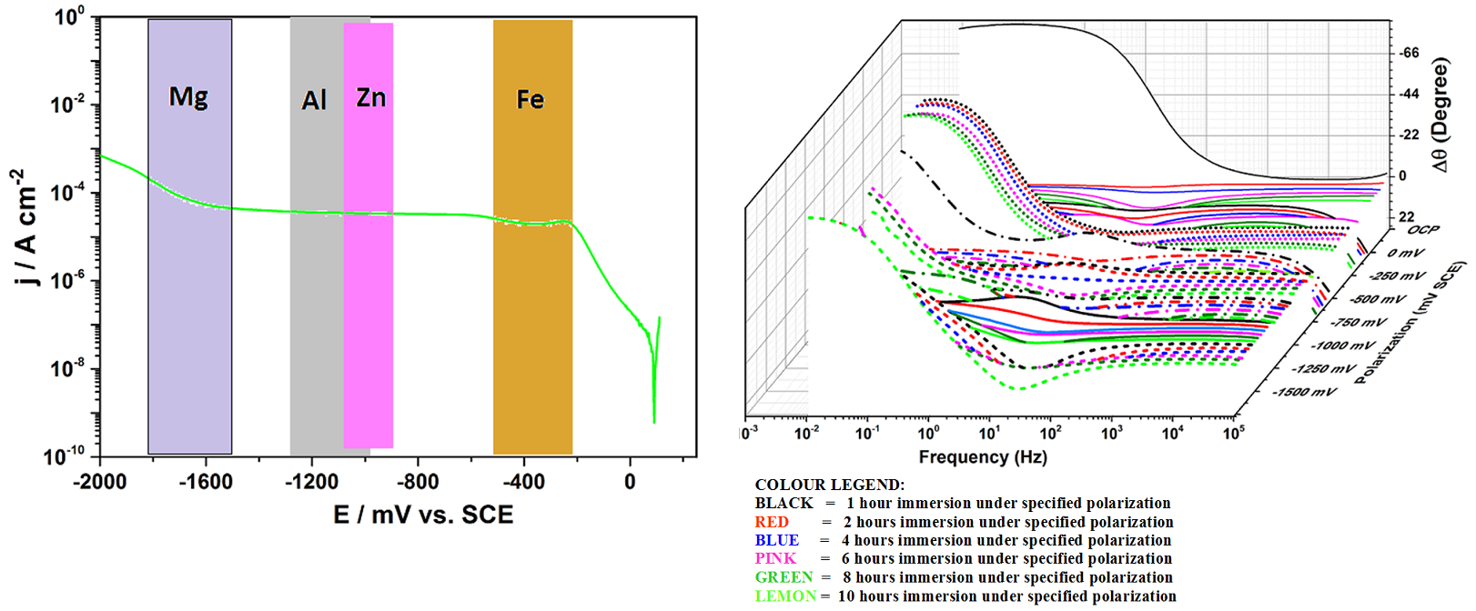
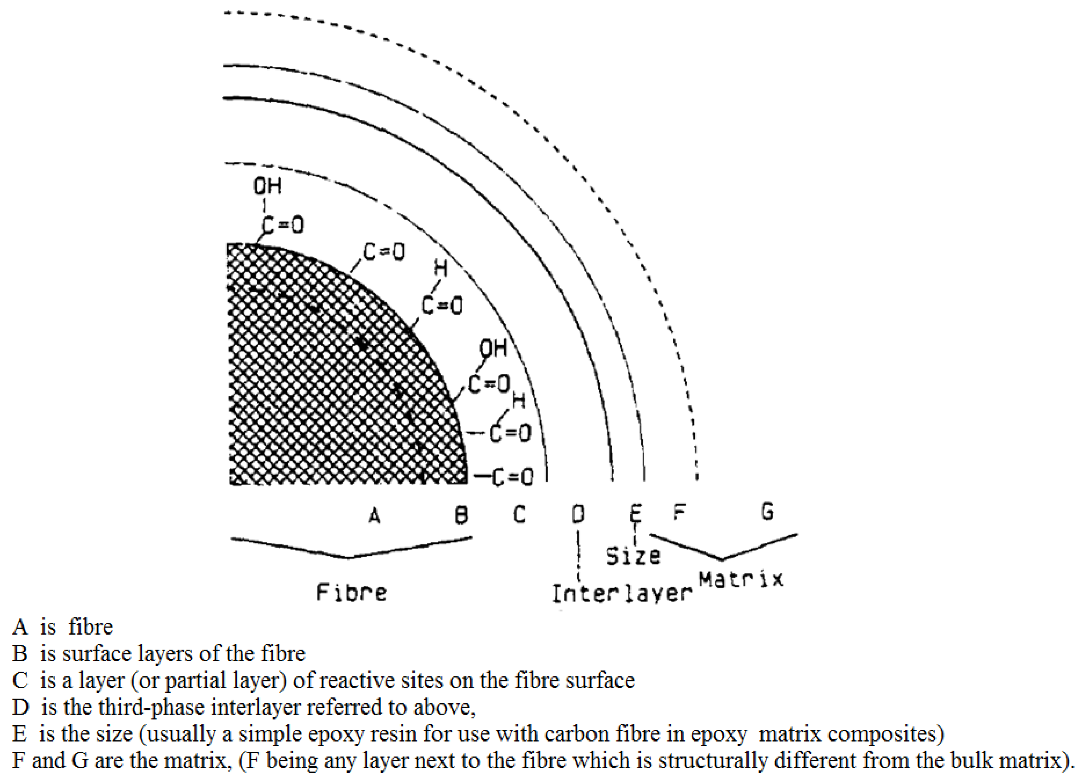
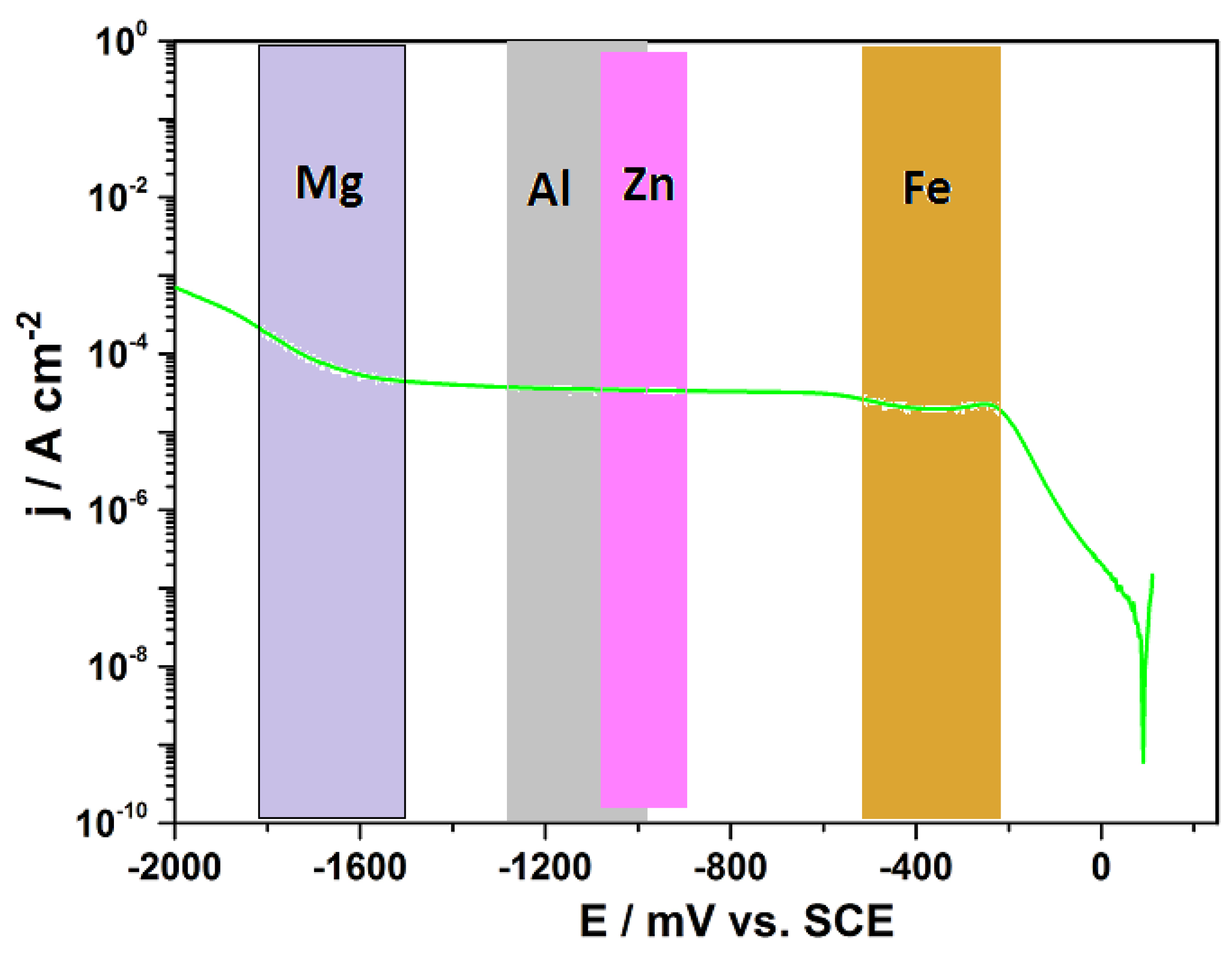
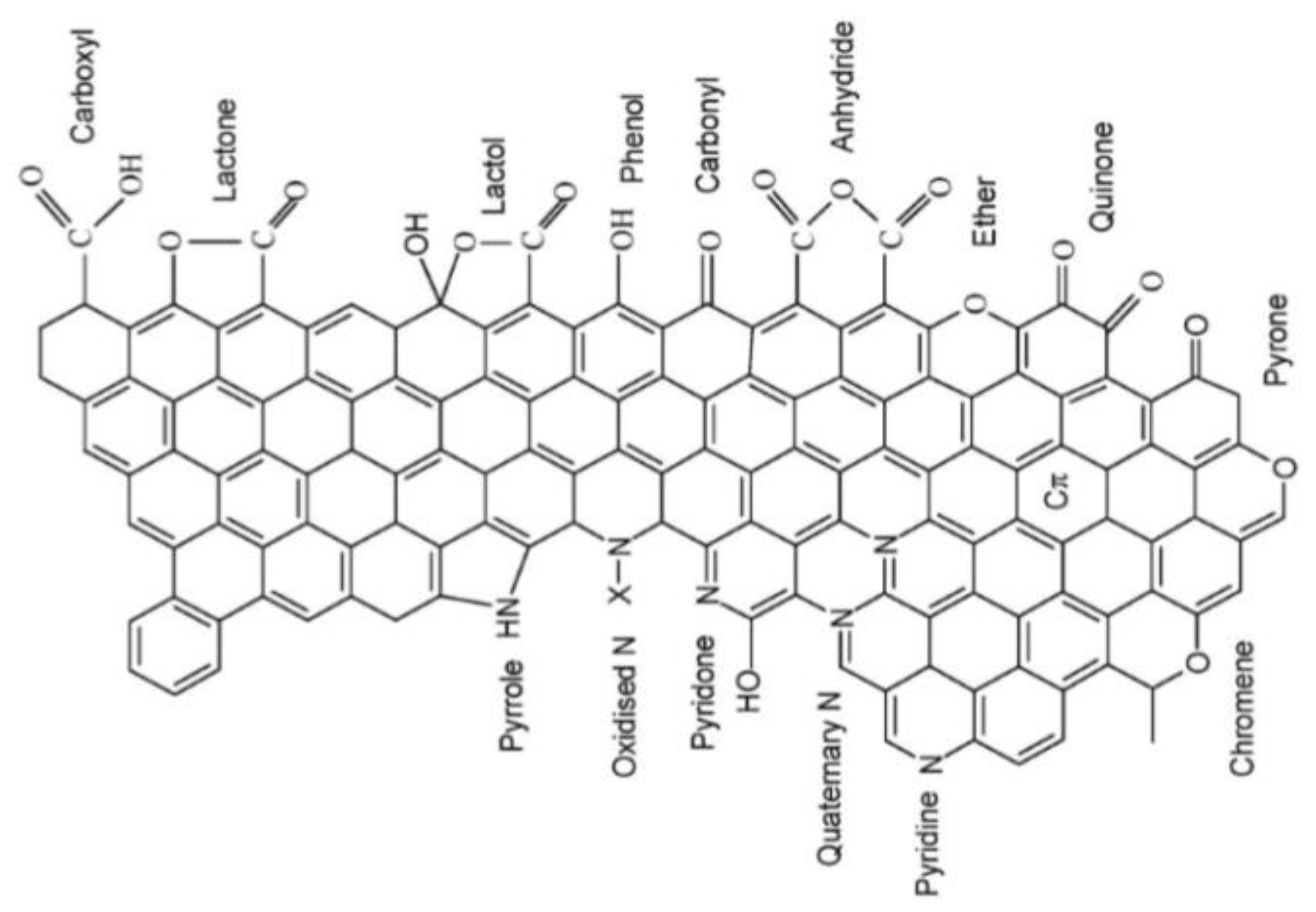
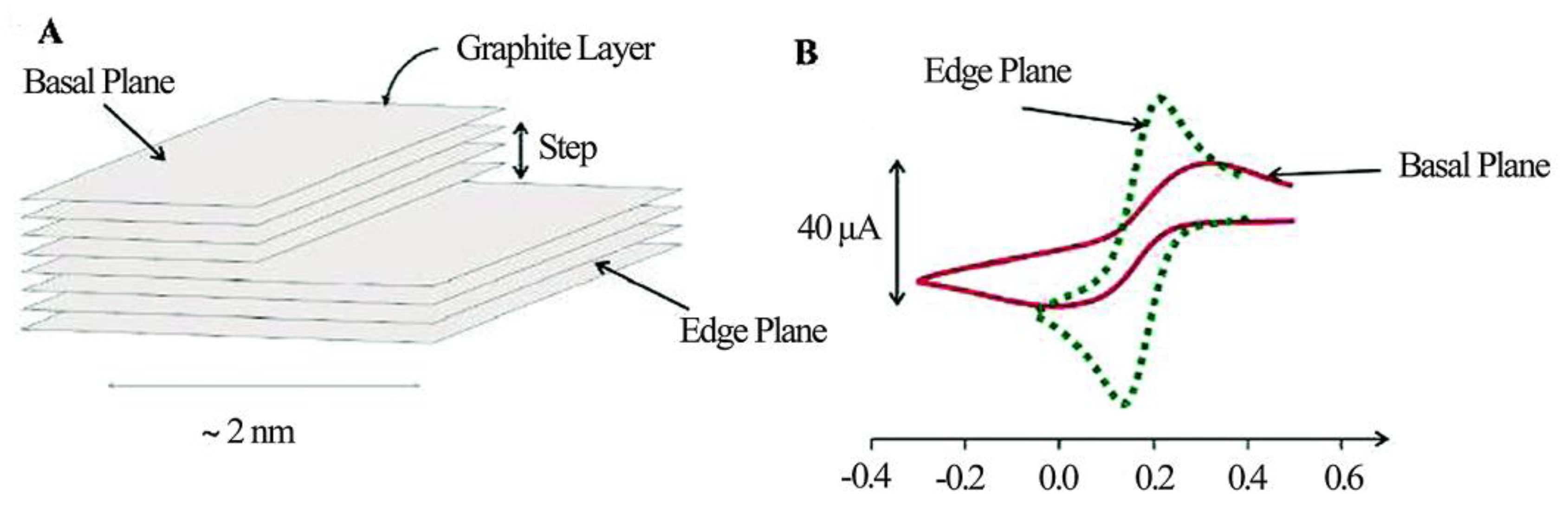
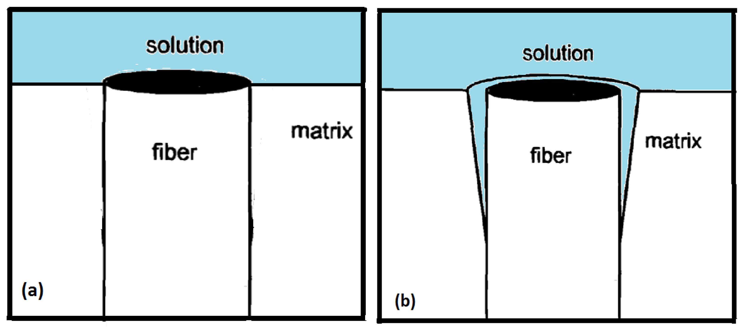
Table 1.
Table of polymeric matrices commonly employed in aerospace sector (Reprinted by permission from Nature/Springer/Palgrave from Ref. [101]). PPS: polyphenylene sulfide; PEEK: polyether ether ketone.
Table 1.
Table of polymeric matrices commonly employed in aerospace sector (Reprinted by permission from Nature/Springer/Palgrave from Ref. [101]). PPS: polyphenylene sulfide; PEEK: polyether ether ketone.
| Thermosets | Thermoplastics | |||
|---|---|---|---|---|
| Forms Cross-Linked Networks in Polymerization Curing by Heating | No Chemical Change | |||
| Epoxies | Phenolics | Polyester | Polyimides | PPS, PEEK |
|
|
|
|
|
|
|
| ||
|
|
| ||
|
|
|
| |
|
|
|
| |
|
|
|
| |
Table 2.
Table of reported values of electrical conductivity for modified carbon-epoxy composites (* denotes conductivity values reported in S/m: an and un-an denotes measurements on annealed and un-annealed samples; where a frequency is indicated conductivity values were read from the conductivity spectra at the indicated frequency). CNF: carbon nanofiber; MWCNT: multi-walled carbon nanotube; SWCNT: single-wall carbon nanotubes.
| Composite System | Filler Used | Filler wt % | Electrical Conductivity (S/cm) | Reference |
|---|---|---|---|---|
| CNF-Epoxy matrix | CNF | 0.1–1 | 2 ×10⁻⁶ to 4 ×10⁻³ | Bal (2010) Ref. [232] |
| CNT-polystyrene | MWCNT | 0.5–4 | (1 × 10⁻¹⁰ to 1 S/cm) (1 × 10⁻⁸ to 1 S/m)* | Cipriano et al. (2008) Ref. [264] |
| CNF-polystyrene | CNF | 3–15 | 1 × 10⁻¹⁰ to 10−2 S/cm (an) 1 × 10⁻¹⁰ to 10−5 S/cm (un-an) (1 × 10⁻⁸ to near 1 S/m)* | Cipriano et al. (2008) Ref. [264] |
| CNT-polycarbonate | MWCNT | 0.75–3 | 1 × 10⁻¹⁴ to > 10−2 S/cm (at 1 Hz) | Pötschke et al. (2004a) Ref. [266] |
| CNT-polycarbonate | MWCNT | 0.875 | ≈ 10−3 S/cm (post annealing at 230 °C) | Alig et al. (2007) Ref. [268] |
| CNT-polycarbonate | SWCNT MWCNT | 1 × 10⁻¹³ to > 10−3 S/cm (at 1 Hz during mixing) | Pötschke et al. (2004b) Ref. [269] | |
| CNT-polycarbonate | MWCNT | 0–5 | 1 × 10⁻¹⁶ to ≈10−2 S/cm | Pötschke et al. (2003) Ref. [270] |
| CNT-epoxy CNF-polypropylene CNF-polyethylene | SWCNT CNF CNF | 0–40 0–40 0–40 | 1 ×10⁻¹⁶ to ≈ 10−7 S/cm 1 × 10⁻¹⁷ to ≈ 10−7 S/cm 1 × 10⁻¹⁷ to ≈ 10−7 S/cm | Lozano et al. (2001) Ref. [264] |
© 2019 by the authors. Licensee MDPI, Basel, Switzerland. This article is an open access article distributed under the terms and conditions of the Creative Commons Attribution (CC BY) license (http://creativecommons.org/licenses/by/4.0/).
Share and Cite
MDPI and ACS Style
Ofoegbu, S.U.; Ferreira, M.G.S.; Zheludkevich, M.L. Galvanically Stimulated Degradation of Carbon-Fiber Reinforced Polymer Composites: A Critical Review. Materials 2019, 12, 651. https://doi.org/10.3390/ma12040651
AMA Style
Ofoegbu SU, Ferreira MGS, Zheludkevich ML. Galvanically Stimulated Degradation of Carbon-Fiber Reinforced Polymer Composites: A Critical Review. Materials. 2019; 12(4):651. https://doi.org/10.3390/ma12040651
Chicago/Turabian StyleOfoegbu, Stanley Udochukwu, Mário G.S. Ferreira, and Mikhail L. Zheludkevich. 2019. "Galvanically Stimulated Degradation of Carbon-Fiber Reinforced Polymer Composites: A Critical Review" Materials 12, no. 4: 651. https://doi.org/10.3390/ma12040651
Note that from the first issue of 2016, this journal uses article numbers instead of page numbers. See further details here.