1. Introduction
In the food industry, it is common to protect metal elements with non-stick coatings [
1]. This is due to several reasons [
2]: preventing food from sticking to substrates, facilitating cleaning tasks, facilitating demolding, and improving the quality of processed products. In addition, these coatings indirectly protect metal substrates and increase the service life of the elements.
Metal substrates used in the manufacture of trays, molds, and other food utensils must allow contact with food. Aluminum alloys, with certain precautions, meet this condition.
Common non-stick coatings include elastomers, sol-gel coatings (ceramics) in addition to some types of fluoropolymers [
3]. Fluoropolymer coatings possess the following advantages [
4]: high anti-adherence, high thermal stability, high chemical inertia, high scratch resistance, high hardness, high sliding angle, and good fixation to the substrate, among others.
When the substrates are exposed to a high number of uses (cycles), the coating loses properties: it wears, gets dirty and scratched, and degrades. In order to recover the support, it has to undergo a regeneration process, which basically consists of two stages: the first is a stripping process by thermal action [
5] and the second is a sandblasting process [
6].
1.1. Metals Substrates
The aluminum-magnesium alloys of the AW 5000 series are used intensively to produce trays, utensils, and molds for cooking ovens, among many other applications. They are highly regarded for their ability in cold deformation, weldability, mechanical resistance [
7], and their excellent resistance to corrosion. The alloys EN-AW 5251 H34 and EN AW 5754 H32 are, moreover, thermally non-treatable and allow contact with food within certain limits [
8,
9,
10,
11].
With a similar objective, parts manufactured with aluminized steel are sometimes used. These are flat sheets of a hipoutectoid steel with a thin layer of aluminum-silicon on its two sides or faces. One example is the aluminized steel DX51D AS120 B CO according to the UNE-EN 10346 standard. This flat steel product combines the properties of aluminum, good corrosion resistance, and high thermal conductivity, with the excellent mechanical properties of steel [
12]. To aluminize the steel substrate, a thin layer of an aluminum-silicon alloy [
13] with a silicon content of 8–11% is fixed on the steel surface by a hot dip process. In these aluminized steel substrates, it is also possible to apply a non-stick coating with the same objectives previously mentioned. Both aluminum-magnesium and aluminized steel surfaces can be coated with fluoropolymers [
14].
1.2. Fluoropolymer Coatings
Fluoropolymer coatings are especially suitable in the food industry due to their non-stick properties and chemical inertia [
15]. Among the fluoropolymer resins used are those of polytetrafluoroethylene (PTFE), ethylene–propylene fluoride (FEP), perfluoroalkoxy copolymer (PFA), or a combination thereof [
16]. These coatings are endowed with a very low surface energy [
17].
Fluoropolymer coatings on metal substrates are formed by several layers. The layers are usually applied by spraying aqueous dispersions [
18] and by electrodeposition of fluoropolymer powder particles [
19]. The first layer serves to ensure a high bond to the metal substrate and allow subsequent anchoring of the second layer. The first layer, in this type of coating, should be dried in the oven at about 150 °C. The following layers should be polymerized between 390 and 425 °C, depending on the fluoropolymer [
16].
1.3. Stripping
Coatings have a certain useful life, since, with use, they wear, scratch, degrade, and get dirty. At this point the deteriorated coatings are removed before applying a new coating. Parts and metal elements have, in many cases, a high value and, in this way, can be reused [
20].
There are many industrial processes that are used in paint stripping, amongst them abrasive blasting [
21], high pressure water jet [
22], the use of plasma spraying [
23], chemical procedures [
24], cryogenic techniques [
25], laser [
26], high-density light pulses [
27], pyrolysis, and certain combinations. Pyrolysis shows the highest rates for stripping [
28] but needs to reach temperatures of 500 °C to ensure the degradation of the fluoropolymers.
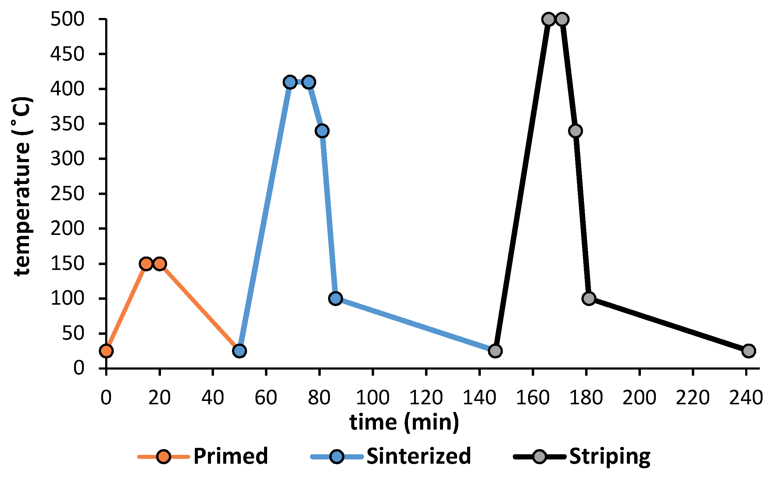
In short, metallic substrates coated with PTFE, FEP, or PFA undergo various thermal cycles. Initially, drying at (150 °C), curing (390–425 °C) and afterward, the worn coating must undergo a removal of the coating at 500 °C. Finally, the parts are cleaned with sandblasting, very often with alumina particles, in order to eliminate any spent coating residue and prepare the surface for the new coating.
It is to be expected that in the end, the substrates may undergo some modifications in mechanical and superficial properties during their lifespan. Nevertheless, there have not been any studies found in the literature that tackle this problem.
1.4. Objetive of the Work
The objective of the present study is to evaluate the variation of the mechanical properties and microstructures of the materials commonly used in the industry of baking trays, utensils, and molds for bakery products. We focus on magnesium aluminum alloys, EN AW 5251 H34 [
29], EN AW 5754 H32 [
30] and aluminized steel DX51D AS120 B [
31]. Modifications will be studied after two cycles of drying, curing-polymerizing, and removing the coating.
Additionally, it has been considered necessary to know the effects that may occur on the aluminium-silicon protective layer of the aluminized steel used in the study.
2. Materials and Methods
For the test program, 10 units of 140 mm × 120 mm were prepared for each alloy studied. The sheets were supplied by CAMEBE (Carpinteria Metalica Bengolea, Castro Urdiales, Spain). The aluminum-magnesium alloys (EN AW 5251 H34, EN AW 5754 H32) have a thickness of 1.2 mm and 1 mm for aluminized steel sheets (DX51D AS120 B).
The chemical composition of magnesium aluminum alloys and the aluminum–silicon layer of aluminized steel have been studied by X-ray microanalysis (EDX) JEOL JSM 6300 (JEOL, Peabody, MA, USA). The results are shown in
Table 1 and are compatible with the standard composition.
The thermal treatment consists of the drying of the primer layer, the curing-polymerization, and finally the removal of the coating. All this was carried out in a drying oven (up to 650 °C) with horizontal air circulation. The dimensions of the equipment were 295 mm wide, 340 mm deep and 170 mm high, with 2.7 kW of electrical power (NA 15/65, Nabertehem GmbH, Lilienthal, Germany).
Figure 1 shows the thermal cycle to which the samples were exposed. These cycles are applied according to the recommendations of Whitford Company (Whitford Corporation, Elverson, PA, USA), a manufacturer of fluoropolymer resins (PTFE, FEP, and PFA).
2.1. Aluminum-Magnesium Alloys
For aluminum-magnesium substrates, metallographic samples EN-AW 5251 and EN-AW 5754 were prepared using cold-cured acrylic resin to obtain a polished colloidal silica finish. Thereafter, the Barker-type reagent (Struers, Madrid, Spain) was exposed (2 min, 20 V) electrolytically [
32]. In all substrates, the microstructure was analyzed in a cross section and in another parallel to the direction of rolling, both in the reception and after the application and pickling stages of the coatings. Also characterized by a dispersive energy spectrometer (EDS) JEOL JSM 6300 (JEOL, Peabody, MA, USA) the main constituent particles (intermetallic) present in the alloys [
33,
34,
35].
The Vickers hardness was obtained with a Zwick/Roell ZHU250 micro-durometer (Zwick Iberica Testing Equipment S.L, San Cugat del Valles, Barcelona, Spain) using a load of 300 g, according to UNE-ISO 6507 [
36]. The tensile and elongation resistance was established with a 100 kN Zwick Roell Z100 electromechanical press in accordance with the standard, UNE-EN ISO 148-1. Flat traction specimens of standard type 1 were used. The results of the test of hardness and mechanical properties have been obtained as statistical mean values of 5 tests for each state.
2.2. Steel with Thin Layer of Aluminum–Silicon
To study the metallographic characteristics of the steel substrates, metallographic samples DX51D were prepared using hot cured resin with a polished colloidal silica finish. The samples were exposed to the reagent known as Marshall [
37] (Struers, Madrid, Spain). Measurements of the ASTM grain size were made, for which grids were drawn with horizontal lines, over five different observation fields. The number of grains intercepted in a reference length was determined and the intercepted average length,
and grain size,
G, was calculated [
38].
Similar equipment to that used in aluminum-magnesium alloys has been used for the determination of Vickers hardness, tensile strength, and elongation.
The aluminum–silicon layer of the DX51D steel was studied and metallographic specimens were prepared, containing cross-sections of the material. The average thickness of the aluminum–silicon layer of the selected aluminized steel is 20 μm. Taking into account that according to the Al-Si diagram, for the maximum temperature range foreseen in the thermal cycle (500 °C), no phase transformations are to be expected [
39], the mean diameter of the dendrites of the microconstituent α (Al) has been chosen as a possible parameter that can be influenced in the microstructure.
In addition, the influence of the projection treatment with abrasive particles has been studied in the thin aluminum–silicon layer. This is carried out after the stripping of coatings. The purpose of this projection is to clean the substrate of any previous residue and ensure a correct adhesion of the subsequent paint. A Sand Blast Cabinet CAT-990 (Aslak S.L, San Quirze del Valles, Barcelona, Spain) was used with an abrasive of the brown corundum type, RBT9 Gr.60 (Piedra Iberica, Madrid, Spain). The diameter of the projection nozzle was 6.5 mm, with a nozzle distance to the substrate of 200 mm and a pressure of 0.2 MPa. Projections were made in time intervals of 5, 10, and 15 s. The conditions of this test have been obtained by the data provided by Tecnimacor S.L (Villafranca de Cordoba, Cordoba, Spain), industry specialists in non-stick coatings.
3. Results
3.1. Aluminum-Magnesium Alloys
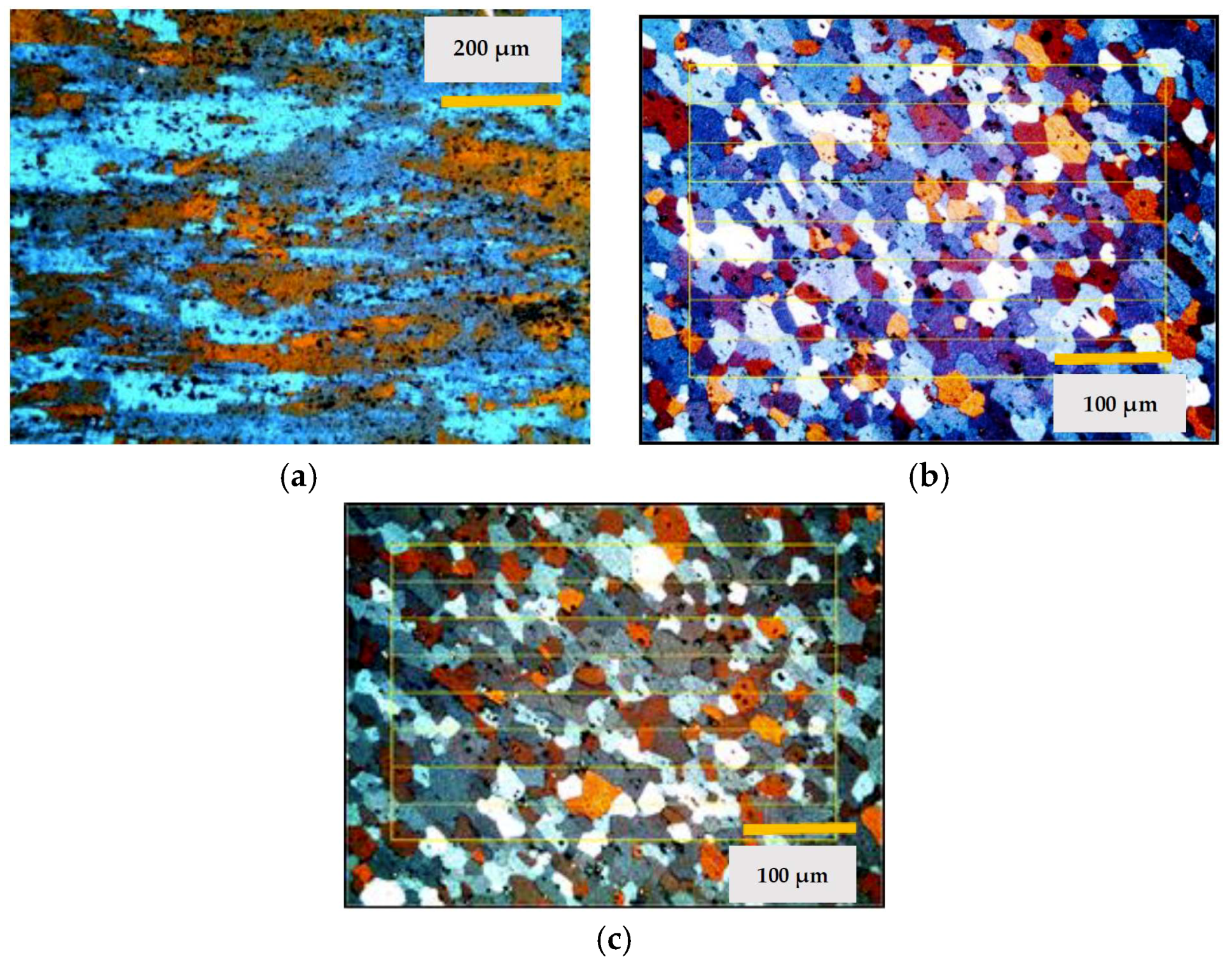
Micrographs were recorded of the aluminum in their supply state and after each cycle studied. The supply state of the alloy EN-AW 5251 is H34 which corresponds to a grade of ½ hard.
Figure 2 shows the images of the states studied.
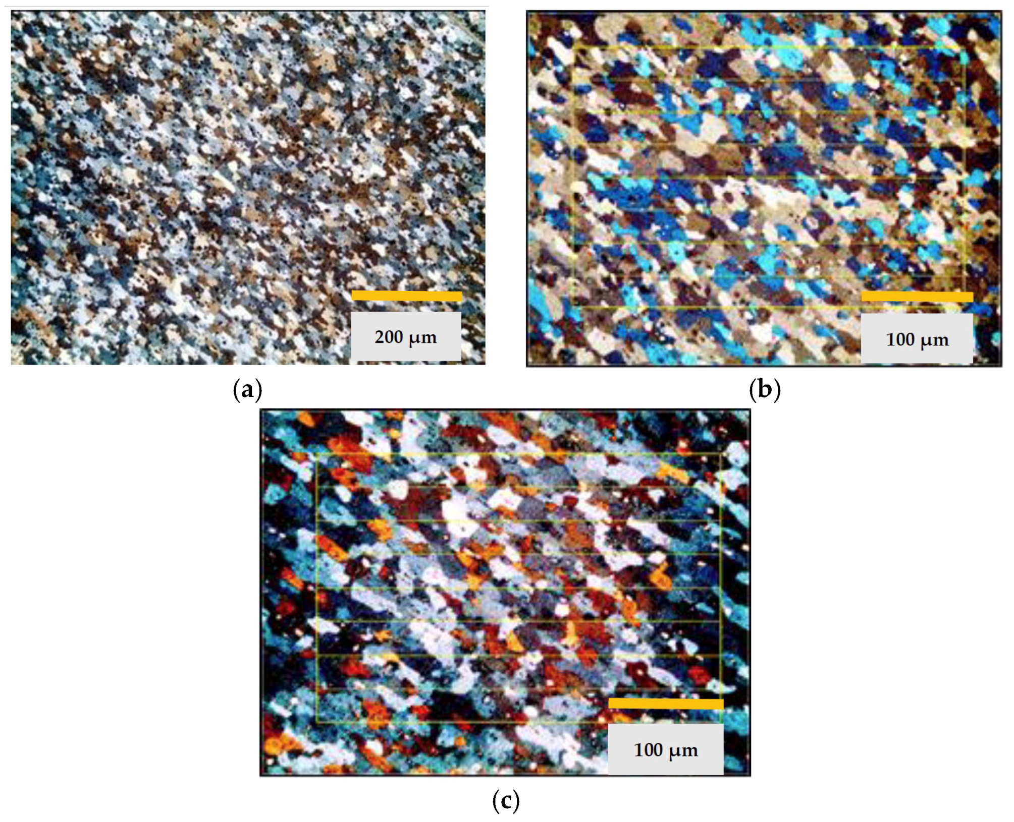
The images obtained of the alloy EN-AW 5754 are shown in
Figure 3. In this case, the supply state was H32 which corresponds to ¼ hard.
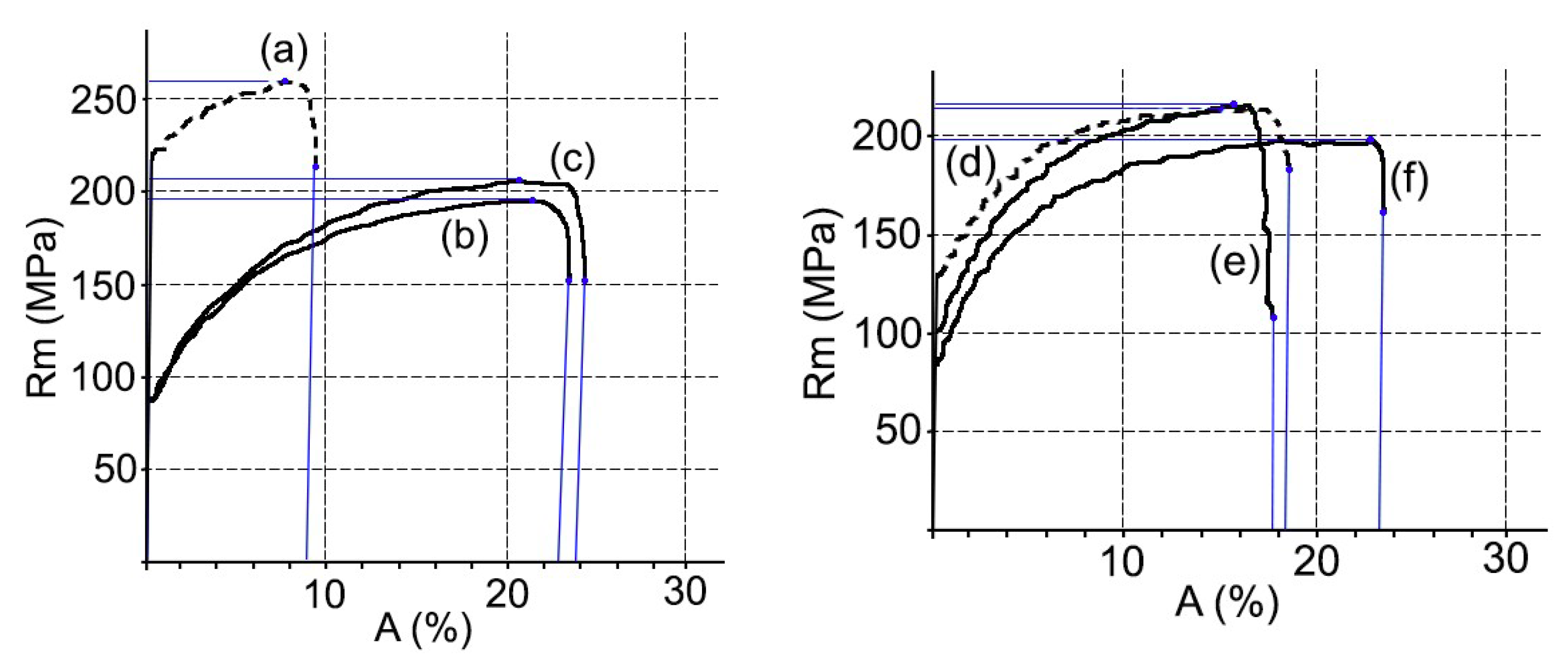
At the same time, the mechanical properties, hardness, elongation, and tensile strength were studied, see
Figure 4. On the other hand, the ASTM grain size and the fractions of area in % of the constituent particles that were characterized as Mg
xSi and α-Al (Fe, Mn) Si. All results are shown in
Table 2.
3.2. Steel with Thin Layer of Aluminum–Silicon
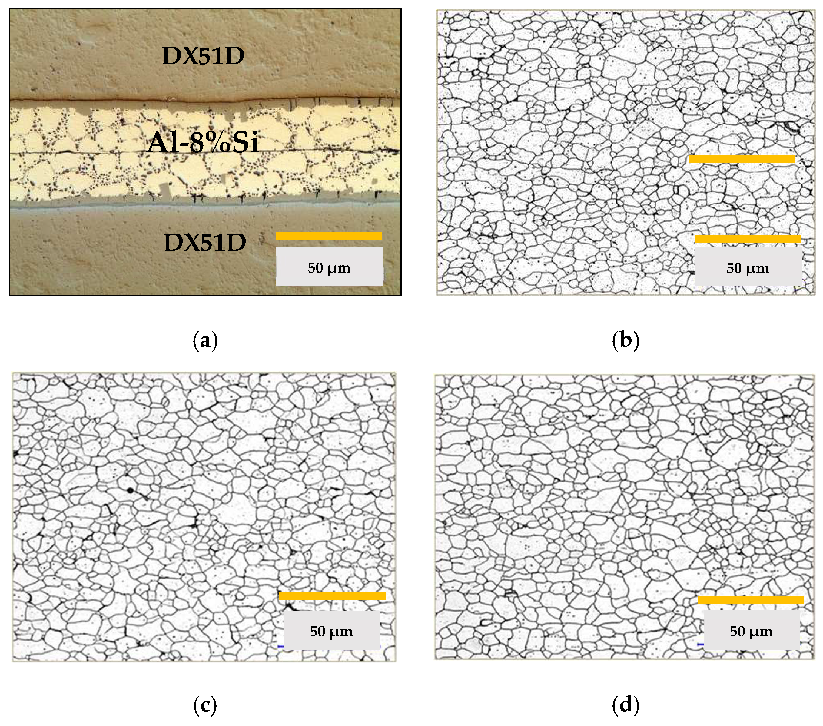
The metallographic images, see
Figure 5, of the DX51D substrates were studied in the state of supply and after each of the two complete thermal cycles: drying of the base layer, polymerization-sintering of the final layer, and elimination of the coating. In the images, a totally ferritic structure is shown, typical of a steel with a very low carbon content in the annealed state.
The results obtained for the mechanical properties and microstructure are shown in
Figure 6 and
Table 3.
Finally, the aluminized steel substrates have been evaluated after the projection with abrasives using different time intervals at a pressure of 0.2 MPa. The results obtained are shown in
Figure 7.
4. Discussion
In the case of aluminum alloy substrates EN-AW 5251 and EN-AW5457, the decrease in hardness and mechanical properties is mainly explained by the recrystallization that gave rise to the alloys after thermal cycle 1 [
28]. In the recrystallized state, the variation in grain size between cycle 1 and cycle 2 is insignificant, as shown in the metallographic images and
Table 2.
Changes in the mechanical properties between the supply state and the thermal cycles 1 and 2 are more intense in alloy EN AW 5251. Thus, the tensile strength decreases between 23–21%, the Vickers hardness between 27–26%, and the percentage elongation increases from 10.5% to 22–21%. In alloy AW 5754, the tensile strength decreases between 7.5–10%, the hardness Vickers 20–21%, and the percentage elongation goes from 18.7% to 20.1–23.1%.
However, after thermal cycles 1 and 2, the aluminum-magnesium alloys did not undergo significant changes in their microstructure or mechanical properties, as can be deduced from the values in
Table 2. This may be due to the fact that there has been no modification in the size and distribution of the inter-metallic constituent particles. These particles have a high melting point and are not soluble in the temperature ranges used in the processes studied. In addition to this, the presence of dispersion particles of type Al (Fe, Mn), of submicroscopic size, act to block any movement of grain boundaries and, therefore, their growth [
40,
41].
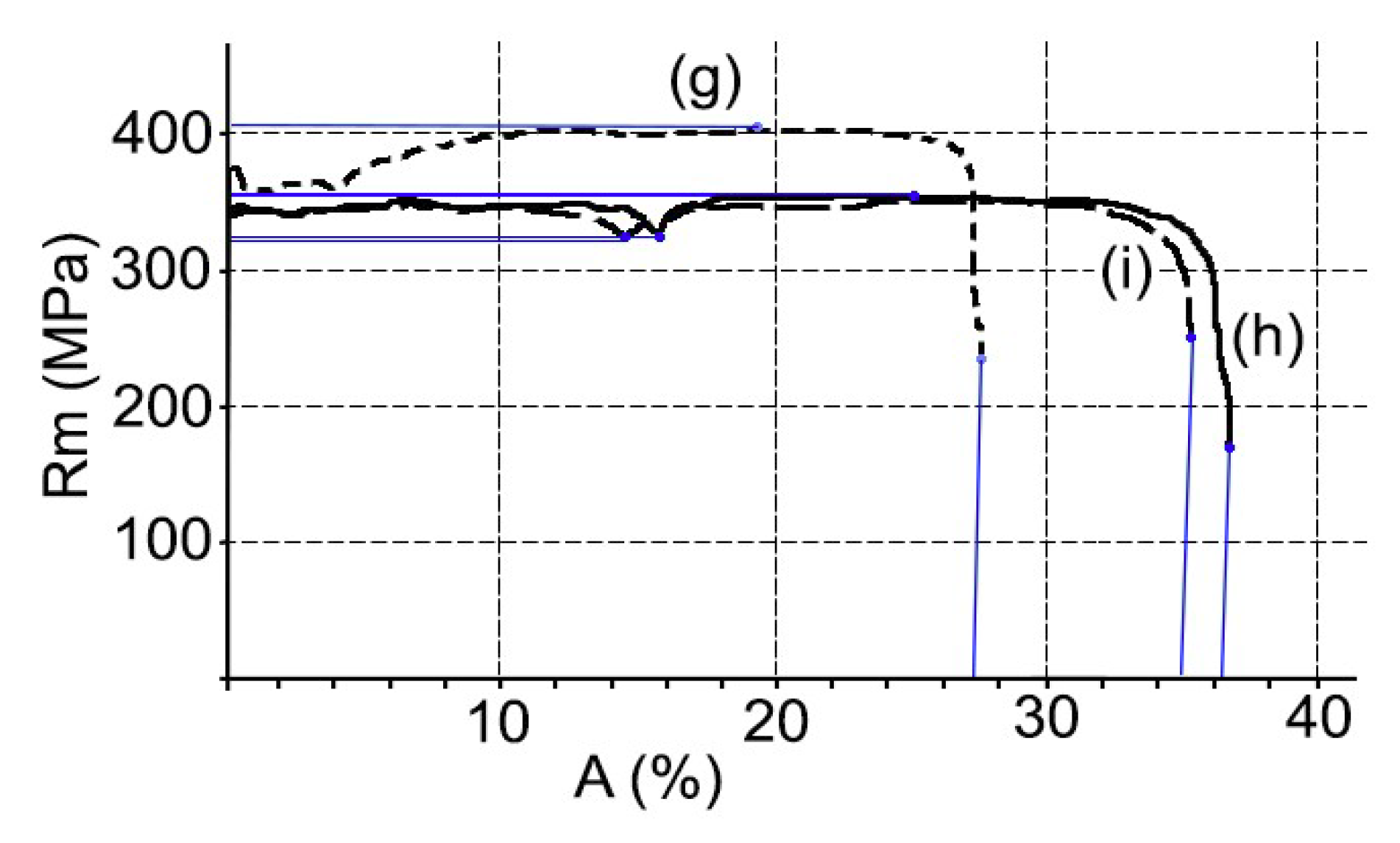
In the case of the aluminized steel substrate DX51D + AS120 B CO, there is a decrease in Vickers hardness and tensile strength and an increase in the percentage of elongation, see
Table 3. In summary, there has been a slight softening of the material between the states of supply and after each of the thermal cycles studied. This phenomenon is explained by a relaxation of the effect of the hardening by deformation that occurs in the rolling of the steel. In addition, in the order of the substructure, a decrease in dislocation density and, probably, a rearrangement, has been required [
42]. This has produced a more stable structure and lower energy, without the microstructure being affected, as can be deduced from the discrete variation of their respective ASTM grain sizes [
43].
Modifications to the mechanical properties of aluminized steel are more limited than those of aluminum-magnesium alloys. In this way, the tensile strength decreases by 12%, the Vickers hardness by 11%, and the percentage elongation increases from 27.9% to 34.2–36.3%.
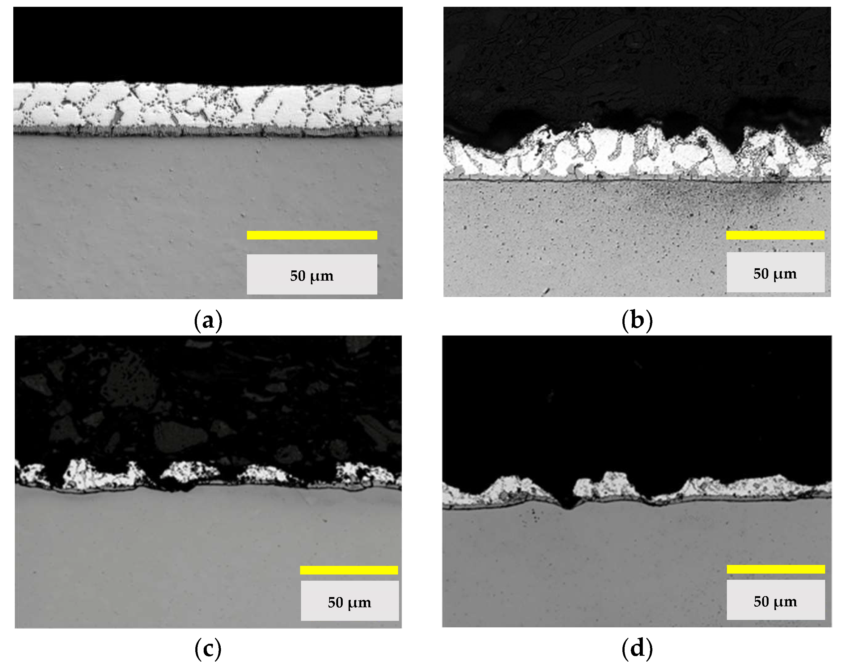
Finally, the functional state of the Al-Si layer of the aluminized steel is studied after the thermal cycles and after the final cleaning of the substrate by abrasive projection. This stage has been applied to both aluminum-magnesium substrates and aluminized steel substrates. This is justified because it is necessary to remove the pyrolyzed coating and prepare the surface adequately for the subsequent coating. After the analysis of the micrographs of
Figure 5, it is concluded that a severe degradation can occur which may compromise the continuity of the Al-Si layer. This point is relevant since it must be taken into account that the contact of the non-stick coating with the steel substrate without aluminum protection can cause contamination by oxidation, the loss of coating properties, and even the lack of fixing of the coating to the substrate.
The tests by means of projection with abrasives with corundum-brown particles show that at a pressure of 0.2 MPa and at a distance of 200 mm, the projection times greater than 5 s produce penetration of the steel substrate.
5. Conclusions
In the present work, the mechanical behavior of three materials (AW 5251, AW 5754, and DX51D + AS120) after being subjected to two thermal-mechanical cycles (primed-sintered-stripping-abrasive projection) has been evaluated. These cycles are similar to those carried out in coating and removal processes of metallic substrates with PTFE, FEP, or PFA.
Based on the results obtained, it can be affirmed that the substrates of aluminum-magnesium and aluminized steel permit successive stages of the application and elimination of coatings of PTFE, PFA, or FEP type and, therefore, can be reused for new coatings. In all cases, there have been variations in the mechanical and structural properties of the substrates. The variations allow the pieces to remain functional, although there has been appreciable softening in them.
Aluminized steel would be the best option if only the mechanical and structural properties were taken into account. However, the continuity of the Al-Si layer can be compromised after the projection by abrasive particles, and this fact can produce contamination by oxidation and can affect the coating. Under the conditions of the standardized test, it can be seen that the projection times of 5 s cannot be exceeded.
With regards to aluminum-magnesium alloys, AW 5754 is more suitable than AW 5215 alloy because its mechanical and structural properties are modified with less intensity. In this case, the substrates do not lose their functionality due to the projection of abrasive particles. The only effect is a slight increase in the roughness of the surface.
Author Contributions
Conceptualization, G.G.-V.; Methodology, all authors; Validation, all authors; Formal Analysis, all authors; Investigation, G.G.-V.; Resources, G.G.-V. and P.E.R.; Data Curation, G.G.-V. and O.R.-A.; Writing-Original Draft Preparation, all authors; Writing-Review & Editing, all authors; Visualization, all authors; Supervision, G.G.-V.; Project Administration, G.G.-V.
Funding
This research received no external funding.
Acknowledgments
The authors thank TECNIMACOR S.L (Córdoba, Spain) for their availability for the supply of the different substrates with the coatings studied and the practical information for the development of the research. In the same way, we would like to show a special thanks to the professor Francisco Moyano, honorary collaborator of the University of Córdoba (Spain), for his thoughtful and useful advice.
Conflicts of Interest
The authors declare no conflict of interest. The funders had no role in the design of the study; in the collection, analyses, or interpretation of data; in the writing of the manuscript, and in the decision to publish the results.
References
- Rossi, S.; Gai, G.; De Benedetto, R. Functional and perceptive aspects of non-stick coatings for cookware. Mater. Des. 2014, 53, 782–790. [Google Scholar] [CrossRef]
- Ashokkumar, S.; Hinke, J.; Adler-Nissen, J. Selection Criteria and Methods for Testing Different Surface Materials for Contact Frying Processes; Technical University of Denmark: Lyngby, Denmark, 2010. [Google Scholar]
- Sánchez-Urbano, F.; Paz-Gómez, G.; Rodríguez-Alabanda, Ó.; Romero, P.; Cabrerizo-Vílchez, M.; Rodríguez-Valverde, M.; Guerrero-Vaca, G. Non-stick coatings in aluminium molds for the production of polyurethane foam. Coatings 2018, 8, 301. [Google Scholar] [CrossRef]
- Thomas, P. The use of fluoropolymers for non-stick cooking utensils. Surf. Coat. Int. 1998, 81, 604–609. [Google Scholar] [CrossRef]
- Baker, B.B.; Kasprzak, D.J. Thermal degradation of commercial fluoropolymers in air. Polym. Degrad. Stab. 1993, 42, 181–188. [Google Scholar] [CrossRef]
- Guerrero, G.R.; Sevilla, L.; Soriano, C. Laser and pyrolysis removal of fluorinated ethylene propylene thin layers applied on EN AW-5251 aluminium substrates. Appl. Surf. Sci. 2015, 353, 686–692. [Google Scholar] [CrossRef]
- Mondolfo, L.F. Aluminum Alloys: Structure and Properties; Butterworths: London, UK, 1976. [Google Scholar]
- Greger, J.L.; GOoetz, W.; Sullivan, D. Aluminum levels in foods cooked and stored in aluminum pans, trays and foil. J. Food Prot. 1985, 48, 772–777. [Google Scholar] [CrossRef]
- Nagy, E.; Jobst, K. Aluminium dissolved from kitchen utensils. Bull. Environ. Contam. Toxicol. 1994, 52, 396–399. [Google Scholar] [CrossRef] [PubMed]
- Karbouj, R.; Desloges, I.; Nortier, P. A simple pre-treatment of aluminium cookware to minimize aluminium transfer to food. Food Chem. Toxicol. 2009, 47, 571–577. [Google Scholar] [CrossRef] [PubMed]
- Ozturk, F.; Pekel, H.; Halkaci, H.S. The effect of strain-rate sensitivity on formability of AA 5754-O at cold and warm temperatures. J. Mater. Eng. Perform. 2011, 20, 77–81. [Google Scholar] [CrossRef]
- Han, Y.; Chen, X.; Li, L.; Zhang, X.; Zhou, D. Effect of Si on the formation and growth of intermetallic compounds at roll-bonded aluminum-steel (Al-St) interface. J. Mater. Eng. Perform. 2018, 27, 333–343. [Google Scholar] [CrossRef]
- Bahadur, A.; Mohanty, O.N. Structural studies of hot dip aluminized cotings on mild steels. Mater. Trans. 1991, 32, 1053–1061. [Google Scholar] [CrossRef]
- Brogly, A.M.; Privas, E.; Gajendran, R.K.; Bistac, S. Tribological properties of non-stick coatings used in bread baking process. In Proceedings of the 8th International Conference on Food Process Engineering, London, UK, 29–30 September 2016. [Google Scholar]
- Richmond, T.G. Demonstrating a lack of reactivity using a Teflon-coated pan. J. Chem. Educ. 1995, 72, 731. [Google Scholar] [CrossRef]
- He, Y.; Farokhzadeh, K.; Edrisy, A. Characterization of thermal, mechanical and tribological properties of fluoropolymer composite coatings. J. Mater. Eng. Perform. 2017, 26, 2520–2534. [Google Scholar] [CrossRef]
- Tavana, H.; Neumann, A.W. Recent progress in the determination of solid surface tensions from contact angles. Adv. Colloid Interface Sci. 2007, 132, 1–32. [Google Scholar] [CrossRef] [PubMed]
- Tangwarodomnukun, V.; Mongkut, K.; Tho, T.; Prombanpong, S.; Mongkut, K.; Tho, T. Industrial Engineering, Management Science and Applications 2015; Springer: Berlin/Heidelberg, Germany, 2015. [Google Scholar]
- Leivo, E.; Wilenius, T.; Kinos, T.; Vuoristo, P.; Mäntylä, T. Properties of thermally sprayed fluoropolymer PVDF, ECTFE, PFA and FEP coatings. Prog. Org. Coatings 2004, 49, 69–73. [Google Scholar] [CrossRef]
- Guerrero, G.R.; Sevilla, L.; Soriano, C. Ablación láser de recubrimientos de politetrafluoretileno (PTFE) aplicados sobre sustratos EN AW-5251. Rev. Metal. 2014, 50, 027. [Google Scholar] [CrossRef]
- Ross, B.; Bares, J.; Fromme, C. A semi-autonomous robot for stripping paint from large vessels. Int. J. Rob. Res. 2003, 22, 617–626. [Google Scholar] [CrossRef]
- Babets, K.; Geskin, E.S. Application of fuzzy logic for modeling of waterjet depainting. Mach. Sci. Technol. 2000, 4, 81–100. [Google Scholar] [CrossRef]
- Yanishevsky, M.; Merati, A.; Bombardier, Y. Effect of Atmospheric Plasma Paint Removal on the Fatigue Performance of 2024-T3 Aluminium Alloy Sheet. J. Miner. Mater. Charact. Eng. 2018, 06, 15–24. [Google Scholar] [CrossRef]
- Hensley, C. A Systems Approach to Depaint Chemistry by Chris Hensley; Aerochem Inc.: Oklahoma City, OK, USA, 2009. [Google Scholar]
- Kirts, R.; Stone, P. Paint Removal Using Cryogenic Processes; Naval Civil Engineering Laboratory: Port Hueneme, CA, USA, 1992. [Google Scholar]
- Klingenberg, M.L.; Naguy, D.A.; Naguy, T.A.; Straw, R.J.; Joseph, C.; Mongelli, G.A.; Nelson, G.C.; Denny, S.L.; Arthur, J.J. Transitioning laser technology to support air force depot transformation needs. Surf. Coat. Technol. 2007, 202, 45–57. [Google Scholar] [CrossRef]
- Grapperhaus, M.J.; Schaefer, R.B. Lead paint removal with high-intensity light pulses. Environ. Sci. Technol. 2006, 40, 7925–7929. [Google Scholar] [CrossRef] [PubMed]
- Guerrero-Vacas, G. Análisis Comparativo de los Procesos de Eliminación de Recubrimientos Antiadherentes Fluoro-Poliméricos en Superficies Metálicas entre Tecnologías Láser y Pirolíticas. Ph.D. Thesis, Universidad de Málaga, Malaga, Spain, 2013. [Google Scholar]
- AENOR UNE 38347. Wrought Aluminium and Aluminium Alloys. 5000 Series. AlMg. Alloy EN AW-5251/EN AW-AlMg2; AENOR: Madrid, Spain, 2004. [Google Scholar]
- AENOR UNE 38339. Wrought Aluminium and Aluminium Alloys. 5000 Series AlMg. Alloy EN AW-5754/EN-AW-AlMg3; AENOR: Madrid, Spain, 2003. [Google Scholar]
- AENOR UNE-EN 10346. Continuously Hot-Dip Coated Steel Flat Products for Cold Forming. Technical Delivery Conditions; AENOR: Madrid, Spain, 2015. [Google Scholar]
- Vander, V.; Baldwin, W. Metallography and Microstructures Handbook; ASM International: Materials Park, OH, USA, 2004. [Google Scholar]
- Haghayeghi, R.; Zoqui, E.J.; Bahai, H. An investigation on the effect of intensive shearing on the grain refinement of A5754 aluminium alloy. J. Alloys Compd. 2009, 481, 358–364. [Google Scholar] [CrossRef]
- Vetrano, J.S.; Bruemmer, S.M.; Pawlowski, L.M.; Robertson, I.M. Influence of the particle size on recrystallization growth in Al-Mg-X alloys and grain. Mater. Sci. Eng. A 1997, 238, 101–107. [Google Scholar] [CrossRef]
- Korbel, A.; Embury, J.D.; Hatherly, M.; Martin, P.L.; Erbsloh, H.W. Microstructural aspects of strain localization in AlMg alloys. Acta Metall. 1986, 34, 1999–2009. [Google Scholar] [CrossRef]
- AENOR UNE-EN ISO 6507-1. Metallic Materials. Vickers Hardness Test. Part 1: Test Method (ISO 6507-1:2005); AENOR: Madrid, Spain, 2006. [Google Scholar]
- Bramfitt, B.L.; Benscoter, A.O. Metallographer’s Guide Practices and Procedures for Irons and Steels; ASM International: Materials Park, OH, USA, 2001. [Google Scholar]
- ASTM ASTM E112-10. Standard Test Methods for Determining Average Grain Size; ASTM: West Conshohocken, PA, USA, 2012. [Google Scholar]
- Murray, J.L.; McAlister, A.J. The Al-Si (aluminum-silicon) system. Bull. Alloy Phase Diagr. 1984, 5, 74–84. [Google Scholar] [CrossRef]
- Attallah, M.M. Microstructure-property development in friction stir welds of aluminium-based alloys. 2008. [Google Scholar]
- Verdier, M.; Janecek, M.; Brechet, Y.; Guyot, P. Microstructural evolution during recovery in Al-2.5% Mg alloys. Mater. Sci. Eng. A 1998, 248, 187–197. [Google Scholar] [CrossRef]
- May, J.; Dinkel, M.; Amberger, D.; Höppel, H.W.; Göken, M. Mechanical properties, dislocation density and grain structure of ultrafine-grained aluminum and aluminum-magnesium alloys. Metall. Mater. Trans. A 2007, 38, 1941–1945. [Google Scholar] [CrossRef]
- Humphreys, F.J.; Hatherly, M. Recrystallization and Related Annealing Phenomena; Elsevier: Oxford, UK, 2004. [Google Scholar]
Figure 1.
Thermal cycle 1 applied in substrates EN AW 5251, EN AW 5754, and DX51D AS120 B.
Figure 1.
Thermal cycle 1 applied in substrates EN AW 5251, EN AW 5754, and DX51D AS120 B.
Figure 2.
Metallographic images of EN-AW 5251, (a) microstructure in the supply state; (b) microstructure after thermal cycle 1; (c) microstructure after thermal cycle 2.
Figure 2.
Metallographic images of EN-AW 5251, (a) microstructure in the supply state; (b) microstructure after thermal cycle 1; (c) microstructure after thermal cycle 2.
Figure 3.
Metallographic images of EN-AW 5754, (a) microstructure in the supply state; (b) microstructure after thermal cycle 1; (c) microstructure after thermal cycle 2.
Figure 3.
Metallographic images of EN-AW 5754, (a) microstructure in the supply state; (b) microstructure after thermal cycle 1; (c) microstructure after thermal cycle 2.
Figure 4.
Stress–strain curves: AW 5241 supply (a), AW 5251 after cycle 1 (b), AW 5251 after cycle 2 (c), AW 5754 supply (d), AW 5754 after cycle 1 (e), and AW 5754 after cycle 2 (f).
Figure 4.
Stress–strain curves: AW 5241 supply (a), AW 5251 after cycle 1 (b), AW 5251 after cycle 2 (c), AW 5754 supply (d), AW 5754 after cycle 1 (e), and AW 5754 after cycle 2 (f).
Figure 5.
Metallographic images of DX51D steel, (a) detail of Al-Si coating in a set-up of sheets; (b) microstructure in supply state; (c) microstructure after thermal cycle 1; (d) microstructure after thermal cycle 2.
Figure 5.
Metallographic images of DX51D steel, (a) detail of Al-Si coating in a set-up of sheets; (b) microstructure in supply state; (c) microstructure after thermal cycle 1; (d) microstructure after thermal cycle 2.
Figure 6.
Stress–strain curve: DX51D supply (g); DX51D after cycle 1 (h); DX51D after cycle 2 (i).
Figure 6.
Stress–strain curve: DX51D supply (g); DX51D after cycle 1 (h); DX51D after cycle 2 (i).
Figure 7.
Micrographs of the Al-Si coating of the steel sheet DX1D + AS120, (a) state of supply; (b) after thermal cycle 2 and abrasive projection with brown corundum at 0.2 MPa for 5 s; (c) for 10 s and (d) for 15 s.
Figure 7.
Micrographs of the Al-Si coating of the steel sheet DX1D + AS120, (a) state of supply; (b) after thermal cycle 2 and abrasive projection with brown corundum at 0.2 MPa for 5 s; (c) for 10 s and (d) for 15 s.
Table 1.
Chemical composition (wt.%) of aluminum-magnesium substrates and the aluminum-silicon layer of aluminized steel.
Table 1.
Chemical composition (wt.%) of aluminum-magnesium substrates and the aluminum-silicon layer of aluminized steel.
| Substrates | Mg | Si | Fe | Mn | Cu | Zn | Cr | Ti | Al |
|---|
| EN AW 5251 | 1.9 | 0.15 | 0.4 | 0.5 | 0.1 | 0.3 | 0.02 | 0.01 | rest |
| EN AW 5754 | 2.5 | 0.46 | 0.56 | 0.27 | - | - | - | - | rest |
| Layer Al-Si AS120 B | 0.01 | 8.3 | 0.45 | 0.1 | 0.05 | - | - | - | rest |
Table 2.
ASTM grain size, tensile strength (Rm), elongation rupture point (A50), Vickers hardness (HV) and % constituent particles on EN AW 5251 and EN AW 5754.
Table 2.
ASTM grain size, tensile strength (Rm), elongation rupture point (A50), Vickers hardness (HV) and % constituent particles on EN AW 5251 and EN AW 5754.
| Alloy/State | Grain-Size (µm)/ASTM | Rm (MPa) | A50 (%) | HV 300 (g) | Area Fraction (%) α-Al (Fe, Mn) Si/MgxSi |
|---|
| AW 5251/Supply | - | 255.3 ± 2.2 | 10.5 ± 2.8 | 70.6 ± 2.1 | 2.52/0.14 |
| AW 5251/After cycle 1 | 8.35 ± 0.28/11 | 196.1 ± 1.5 | 22.0 ± 1.3 | 52.1 ± 2.1 | 2.04/0.05 |
| AW 5251/After l cycle 2 | 8.29 ± 0.32/11 | 202.1 ± 1.9 | 21.3 ± 2.2 | 51.0 ± 2.0 | 1.80/0.05 |
| AW 5754/Supply | - | 220.7 ± 2.4 | 18.7 ± 1.1 | 71.5 ± 1.8 | 2.58/0.19 |
| AW 5754/After l cycle 1 | 8.51 ± 0.21/11 | 206.5 ± 1.0 | 20.1 ± 1.9 | 59.5 ± 2.2 | 2.49/0.28 |
| AW 5754/After cycle 2 | 8.45 ± 0.26/11 | 200.6. ± 2.2 | 23.1 ± 2.0 | 58.1 ± 1.6 | 2.08/0.17 |
Table 3.
ASTM grain-size, tensile strength (Rm), elongation of rupture (A50), Vickers hardness (HV) of steel DX51D and average diameter (µm) of the micro-constituent dendrites α (Al) of the layer of Al-Si.
Table 3.
ASTM grain-size, tensile strength (Rm), elongation of rupture (A50), Vickers hardness (HV) of steel DX51D and average diameter (µm) of the micro-constituent dendrites α (Al) of the layer of Al-Si.
| State | Grain-Size (µm)/ASTM | Rm (MPa) | A50 (%) | HV 300 (g) | Φ Average (µm) Dendrites α (Al) |
|---|
| Supply | 11.33 ± 0.25/10 | 401 ± 3.6 | 27.9 ± 2.6 | 128 ± 1.7 | 10.26 |
| After cycle 1 | 11.28 ± 0.15/10 | 353 ± 2.9 | 34.2 ± 3.1 | 114 ± 1.3 | 10.27 |
| After cycle 2 | 11.23 ± 0.11/10 | 353 ± 4.1 | 36.3 ± 3.2 | 113 ± 1.9 | 11.07 |
© 2018 by the authors. Licensee MDPI, Basel, Switzerland. This article is an open access article distributed under the terms and conditions of the Creative Commons Attribution (CC BY) license (http://creativecommons.org/licenses/by/4.0/).


