
The Effect of MQL on Tool Wear Progression in Low-Frequency Vibration-Assisted Drilling of CFRP/Ti6Al4V Stack Material


Abstract
:1. Introduction
2. Experimental Setup
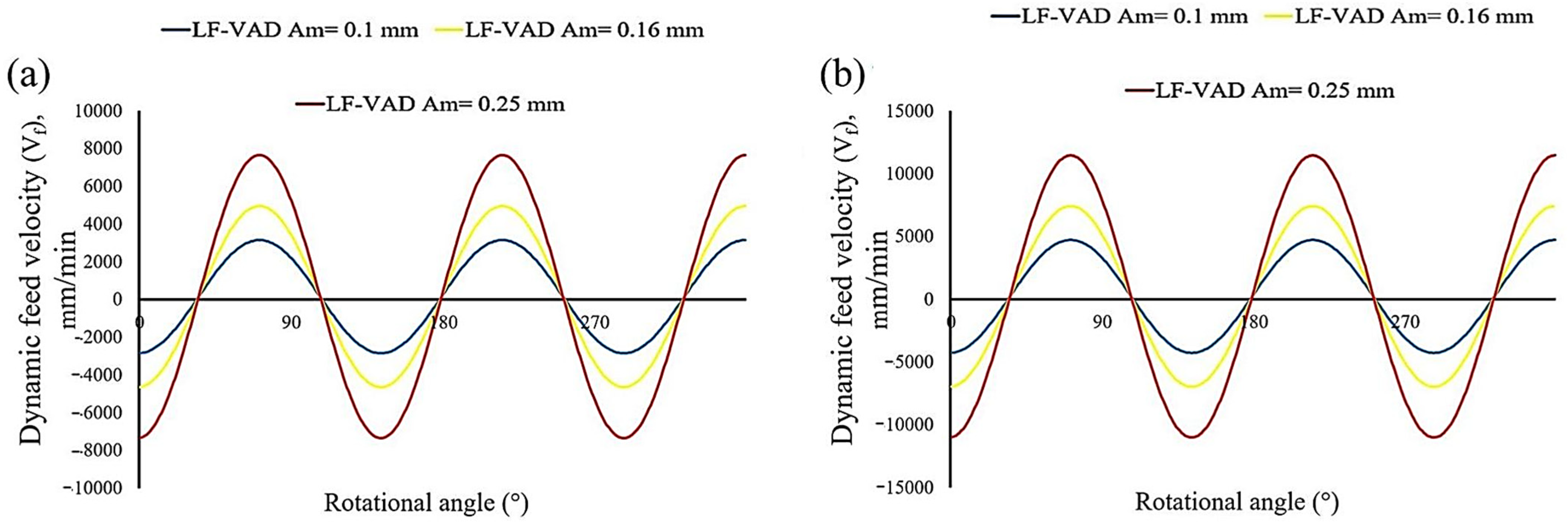
3. Kinematics of VAD
4. Results and Discussion
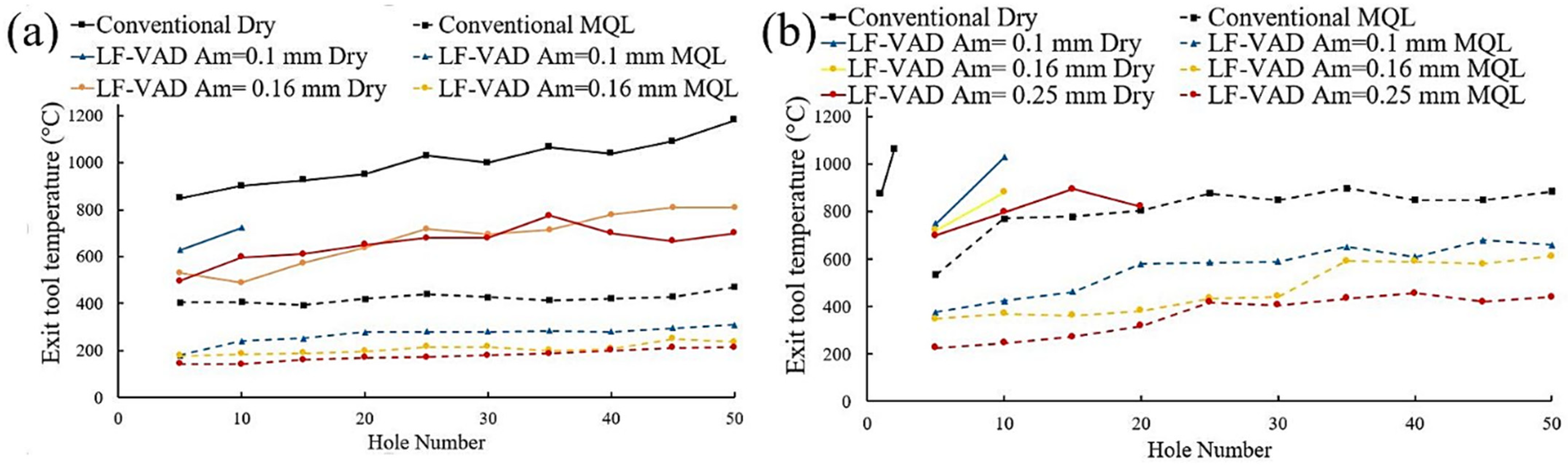
4.1. Cutting Temperature
4.2. Tool Wear Progression and Mechanism
4.2.1. Flank Face
4.2.2. Chisel Edge
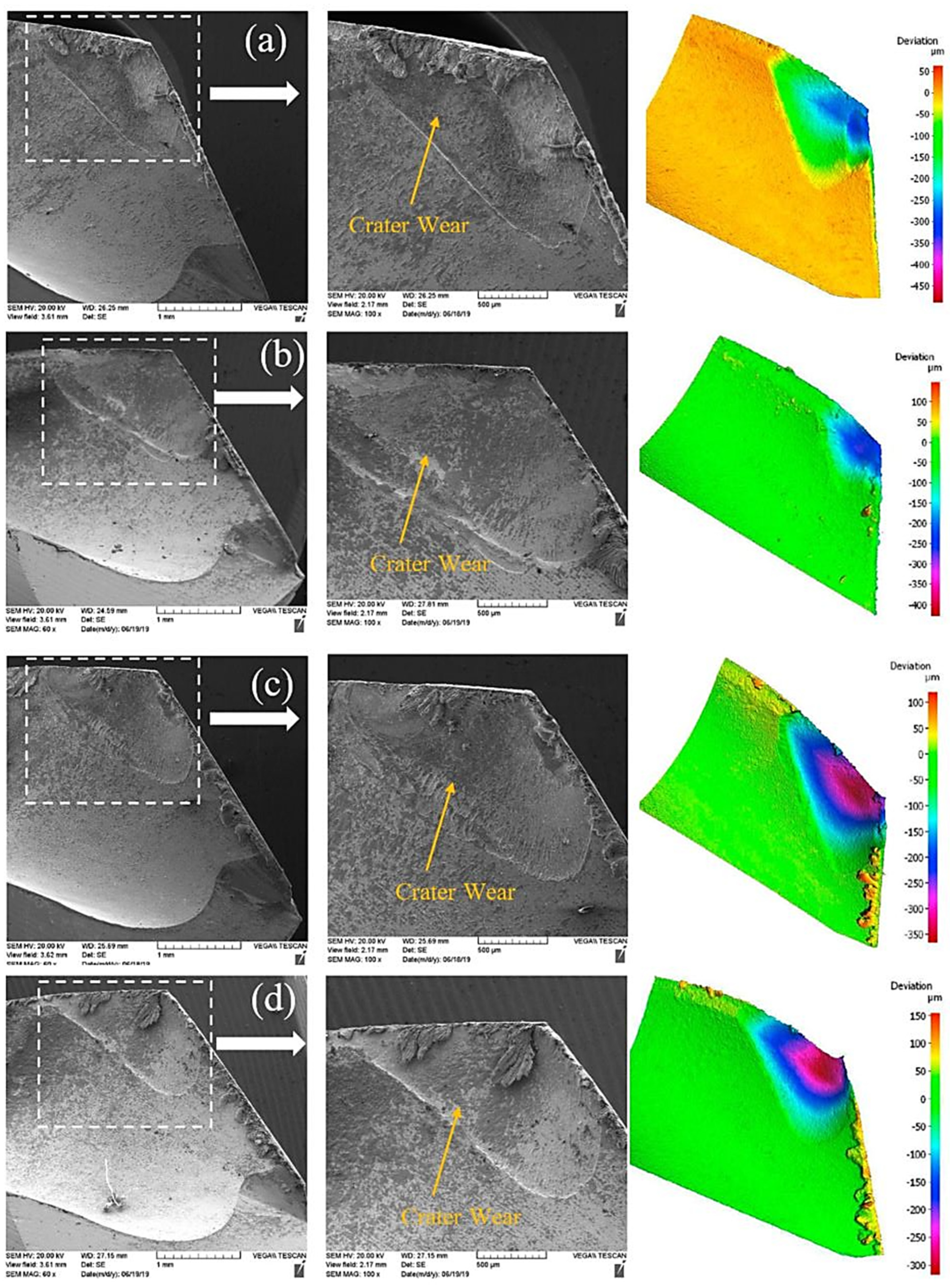
4.2.3. Rake Face
4.3. Effect of Tool Wear on the Exit Delamination
4.4. Effect of Tool Wear on the Geometrical Accuracy
4.5. Burr Height
4.6. MQL vs. Dry Coolant Condition
5. Conclusions
- Compared to the LF-VAD under the dry condition, MQL increased the applicable feed rate from 0.025 mm/rev to 0.075 mm/rev at N = 3000 rpm. The coupled effect of LF-VAD and MQL showed a higher accuracy hole geometry and longer tool life owing to a proper chip evacuation mechanism and optimum cooling condition. This increased feed rate improved machining productivity by 300%.
- Vibration amplitude and cooling medium are critical to the cutting temperature, which showed a significant reduction by up to 65%, compared to the CD dry drilling of CFRP/Ti6Al4V stacks. This reduction contributed to the smaller chip radian, higher tool axial velocity, lower fractional force at the tool–hole wall interface, and the advance of smaller micro coolant droplets to penetrate the tool–chip and tool–workpiece interface. The MQL assistance resulted in a drilling process of 50 holes without any observation of the tool–chip welding phenomenon.
- For all experimental investigations, LF-VAD showed a flank wear land reduction by up to 53%, due to the lower cutting temperature. The flank wear land has a critical impact on tool life evaluation and the machining productivity.
- From the tool examination, the chisel edge was identified as the weakest point for LF-VAD. This observation can be traced back to the repetitive tool–workpiece impact mechanism. On the other hand, the tool outer corner was identified as the most vulnerable area for catastrophic failure during CD.
- The LF-VAD resulted in a reduction of 80% of the maximum BUE height at N = 2000 rpm, while the crater depth was reduced by 33% at N = 3000 rpm.
- Under the MQL condition, LF-VAD produces more consistent hole diameters and no CFRP exit delamination.
Author Contributions
Funding
Institutional Review Board Statement
Informed Consent Statement
Data Availability Statement
Conflicts of Interest
Abbreviations
| VAD | Vibration-assisted drilling |
| LF-VAD | Low frequency vibration-assisted drilling |
| CD | Conventional drilling |
| BUE | Built-up edge |
| MQL | Minimum quantity lubricant |
Notations
| N | Cutting speed (rpm) |
| f | Feed rate (mm/rev) |
| Am | Modulation amplitude (mm) |
| F | Frequency (oscillation/rev) |
References
- Brinksmeier, E.; Janssen, R. Drilling of Multi-Layer Composite Materials consisting of Carbon Fiber Reinforced Plastics (CFRP), Titanium and Aluminum Alloys. CIRP Ann. Manuf. Technol. 2002, 51, 87–90. [Google Scholar] [CrossRef]
- Xu, J.; Mkaddem, A.; El Mansori, M. Recent advances in drilling hybrid FRP/Ti composite: A state-of-the-art review. Comp. Struct. 2016, 135, 316–338. [Google Scholar] [CrossRef] [Green Version]
- Park, K.-H.; Beal, A.; Kwon, P.; Lantrip, J. A comparative study of carbide tools in drilling of CFRP and CFRP-Ti stacks. J. Manuf. Sci. Eng. 2014, 136, 014501. [Google Scholar] [CrossRef]
- Park, K.-H.; Beal, A.; Kwon, P.; Lantrip, J. Tool wear in drilling of composite/titanium stacks using carbide and polycrystalline diamond tools. Wear 2011, 271, 2826–2835. [Google Scholar] [CrossRef]
- Xu, J.; El Mansori, M. Wear characteristics of polycrystalline diamond tools in orthogonal cutting of CFRP/Ti stacks. Wear 2017, 376, 91–106. [Google Scholar] [CrossRef] [Green Version]
- Shyha, I.; Soo, S.L.; Aspinwall, D.; Bradley, S.; Perry, R.; Harden, P.; Dawson, S. Hole quality assessment following drilling of metallic-composite stacks. Int. J. Mach. Tools Manuf. 2011, 51, 569–578. [Google Scholar] [CrossRef]
- Kim, D.; Ramulu, M. Study on the drilling of titanium/graphite hybrid composites. J. Eng. Mater. Technol. 2007, 129, 390–396. [Google Scholar] [CrossRef]
- Rawat, S.; Attia, H. Wear mechanisms and tool life management of WC–Co drills during dry high speed drilling of woven carbon fibre composites. Wear 2009, 267, 1022–1030. [Google Scholar] [CrossRef]
- Hussein, R.; Sadek, A.; Elbestawi, M.A.; Attia, M.H. Surface and microstructure characterization of low-frequency vibration-assisted drilling of Ti6Al4V. Int. J. Adv. Manuf. Technol. 2019, 103, 1443–1457. [Google Scholar] [CrossRef]
- Hussein, R.; Sadek, A.; Elbestawi, M.A.; Attia, M.H. An Investigation into Tool Wear and Hole Quality during Low-Frequency Vibration-Assisted Drilling of CFRP/Ti6Al4V Stack. J. Manuf. Mater. Proc. 2019, 3, 63. [Google Scholar] [CrossRef] [Green Version]
- Poutord, A.; Rossi, F.; Poulachon, G.; M’Saoubi, R.; Abrivard, G. Local approach of wear in drilling Ti6Al4V/CFRP for stack modelling. Procedia CIRP 2013, 8, 316–321. [Google Scholar] [CrossRef] [Green Version]
- Kim, D.; Sturtevant, C.; Ramulu, M. Usage of PCD tool in drilling of titanium/graphite hybrid composite laminate. Int. J. Mach. Mach. Mater. 2013, 13, 276–288. [Google Scholar] [CrossRef]
- Weiss, R.A. Portable Air Feed Peck Drilling of Graphite Composite, Titanium and Other Materials in Dissimilar Combinations; Society of Manufacturing Engineers: Southfield, MI, USA, 1989. [Google Scholar]
- Denkena, B.; Boehnke, D.; Dege, J. Helical milling of CFRP–titanium layer compounds. CIRP J. Manuf. Sci. Technol. 2008, 1, 64–69. [Google Scholar] [CrossRef]
- Wang, H.; Qin, X.; Li, H.; Tan, Y. A comparative study on helical milling of CFRP/Ti stacks and its individual layers. Int. J. Adv. Manuf. Technol. 2016, 86, 1973–1983. [Google Scholar] [CrossRef]
- Pecat, O.; Brinksmeier, E. Low damage drilling of CFRP/titanium compound materials for fastening. Procedia CIRP 2014, 13, 1–7. [Google Scholar] [CrossRef] [Green Version]
- Lonfier, J.; De Castelbajac, C. A Comparison between Regular and Vibration-Assisted Drilling in CFRP/Ti6Al4V Stack. SAE Int. J. Mater. Manuf. 2015, 8, 18–26. [Google Scholar] [CrossRef]
- Sadek, A. Vibration Assisted Drilling of Multidirectional Fiber Reinforced Polymer Laminates. Ph.D. Thesis, McGill University Libraries, Montreal, QC, Canada, 2014. [Google Scholar]
- Li, C.; Xu, J.; Chen, M.; An, Q.; El Mansori, M.; Ren, F. Tool wear processes in low frequency vibration assisted drilling of CFRP/Ti6Al4V stacks with forced air-cooling. Wear 2019, 426, 1616–1623. [Google Scholar] [CrossRef]
- Yang, H.; Chen, Y.; Xu, J.; Ladonne, M.; Lonfier, J.; Fu, Y. Tool wear mechanism in low-frequency vibration–assisted drilling of CFRP/Ti stacks and its individual layer. Int. J. Adv. Manuf. Technol. 2019, 104, 2539–2551. [Google Scholar] [CrossRef]
- Hussein, R.; Sadek, A.; Elbestawi, M.A.; Attia, M. Low-frequency vibration-assisted drilling of hybrid CFRP/Ti6Al4V stacked material. Int. J. Adv. Manuf. Technol. 2018, 98, 2801–2817. [Google Scholar] [CrossRef]
- Rodríguez, A.; Calleja, A.; de Lacalle, L.L.; Pereira, O.; Rubio-Mateos, A.; Rodríguez, G. Drilling of CFRP-Ti6Al4V stacks using CO2-cryogenic cooling. J. Manuf. Proc. 2021, 64, 58–66. [Google Scholar] [CrossRef]
- Pimenov, D.Y.; Mia, M.; Gupta, M.K.; Machado, A.R.; Tomaz, Í.V.; Sarikaya, M.; Wojciechowski, S.; Mikolajczyk, T.; Kapłonek, W. Improvement of machinability of Ti and its alloys using cooling-lubrication techniques: A review and future prospect. J. Mater. Res. Technol. 2021, 11, 719–753. [Google Scholar] [CrossRef]
- Iqbal, A.; Zhao, G.; Zaini, J.; Gupta, M.K.; Jamil, M.; He, N.; Nauman, M.M.; Mikolajczyk, T.; Pimenov, D.Y. Between-the-Holes Cryogenic Cooling of the Tool in Hole-Making of Ti-6Al-4V and CFRP. Materials 2021, 14, 795. [Google Scholar] [CrossRef]
- Senthilkumar, M.; Prabukarthi, A.; Krishnaraj, V. Machining of CFRP/Ti6Al4V stacks under minimal quantity lubricating condition. J. Mech. Sci. Technol. 2018, 32, 3787–3796. [Google Scholar] [CrossRef]
- Pecat, O.; Brinksmeier, E. Tool wear analyses in low frequency vibration assisted drilling of CFRP/Ti6Al4V stack material. Procedia CIRP 2014, 14, 142–147. [Google Scholar] [CrossRef] [Green Version]
- Xu, J.; Ji, M.; Chen, M.; El Mansori, M. Experimental investigation on drilling machinability and hole quality of CFRP/Ti6Al4V stacks under different cooling conditions. Int. J. Adv. Manuf. Technol. 2020, 109, 1527–1539. [Google Scholar] [CrossRef]
- MITIS Engineer. MITIS Tool Holder. Availabe online: https://www.mitis.fr/ (accessed on 10 March 2021).
- YG-1 CANADA GROUP. Availabe online: http://www.yg1.ca/ (accessed on 10 March 2021).
- Pecat, O.; Meyer, I. Low frequency vibration assisted drilling of aluminium alloys. In Proceedings of Advanced Materials Research; Trans Tech Publications: Zurich, Switzerland, 2013; pp. 131–138. [Google Scholar]
- Tai, B.L.; Stephenson, D.A.; Shih, A.J. Workpiece temperature during deep-hole drilling of cast iron using high air pressure minimum quantity lubrication. J. Manuf. Sci. Eng. 2013, 135, 031019. [Google Scholar] [CrossRef]
- Mathew, N.T.; Vijayaraghavan, L. Environmentally friendly drilling of intermetallic titanium aluminide at different aspect ratio. J. Clean. Prod. 2017, 141, 439–452. [Google Scholar] [CrossRef]
- Sadek, A.; Attia, M.; Meshreki, M.; Shi, B. Characterization and optimization of vibration-assisted drilling of fibre reinforced epoxy laminates. CIRP Ann. Manuf. Technol. 2013, 62, 91–94. [Google Scholar] [CrossRef]
- International Organization for Standardization. ISO 3685 Tool-Life Testing with Single Point Turning Tools; ISO: Geneva, Switzerland, 1993. [Google Scholar]
- Kim, S.; Lee, D.; Kang, M.; Kim, J. Evaluation of machinability by cutting environments in high-speed milling of difficult-to-cut materials. J. Mater. Proc. Technol. 2001, 111, 256–260. [Google Scholar] [CrossRef]
- Su, Y.; He, N.; Li, L.; Li, X. An experimental investigation of effects of cooling/lubrication conditions on tool wear in high-speed end milling of Ti-6Al-4V. Wear 2006, 261, 760–766. [Google Scholar] [CrossRef]
- Vieira, J.; Machado, A.; Ezugwu, E. Performance of cutting fluids during face milling of steels. J. Mater. Proc. Technol. 2001, 116, 244–251. [Google Scholar] [CrossRef]
- Yuan, S.; Yan, L.; Liu, W.; Liu, Q. Effects of cooling air temperature on cryogenic machining of Ti–6Al–4V alloy. J. Mater. Proc. Technol. 2011, 211, 356–362. [Google Scholar] [CrossRef]
- Zhang, P.; Churi, N.; Pei, Z.J.; Treadwell, C. Mechanical drilling processes for titanium alloys: A literature review. Mach. Sci. Technol. 2008, 12, 417–444. [Google Scholar] [CrossRef] [Green Version]
- Sharif, S.; Rahim, E.A. Performance of coated- and uncoated-carbide tools when drilling titanium alloy—Ti–6Al4V. J. Mater. Proc. Technol. 2007, 185, 72–76. [Google Scholar] [CrossRef] [Green Version]
- Ramulu, M.; Branson, T.; Kim, D. A study on the drilling of composite and titanium stacks. Compos. Struct. 2001, 54, 67–77. [Google Scholar] [CrossRef]
- Hussein, R.; Sadek, A.; Elbestawi, M.A.; Attia, M.H. Chip Morphology and Delamination Characterization for Vibration-Assisted Drilling of Carbon Fiber-Reinforced Polymer. J. Manuf. Mater. Proc. 2019, 3, 23. [Google Scholar] [CrossRef] [Green Version]


| Machining Parameters | |
|---|---|
| Cutting speed, N | 2000 and 3000 rpm |
| Feed rate, f | 0.075 mm/rev |
| Amplitude, Am | 0.1, 0.16, and 0.25 mm MQL |
| Cooling medium | |
| Cutting Tool | |
| Material | Tungsten Carbide |
| Diameter | 6 mm |
| Point angle | 118° |
| Helix angle | 20° |
| Manufacturer | YG-1 |
| Workpiece material specification CFRP Titanium alloy Stacking sequence |
CFRP 5.8 ± 0.02 mm/Ti6Al4V 6.75 ± 0.02 mm |
| C | Al | Ti | V | Co | W | Total | |
|---|---|---|---|---|---|---|---|
| Spectrum 1 | 43.42 | 3.86 | 49.57 | 3.15 | 0 | 0 | 100.00 |
| Spectrum 2 | 97.43 | 0.65 | 0.47 | 0.40 | 0.25 | 0.80 | 100.00 |
| Cutting Speed (rpm) | Vibration Amplitude (mm) | Drilled Hole Number | ||||
|---|---|---|---|---|---|---|
| 0–10 | 10–20 | 20–30 | 30–40 | 40–50 | ||
| N = 2000 | Conventional | 0.1–0.2 | ||||
| Am = 0.1 | Free | |||||
| Am = 0.16 | ||||||
| Am = 0.25 | Free | 0.05–0.1 | ||||
| N = 3000 | Conventional | 0.05–0.1 | 0.1–0.2 | 0.2–0.3 | ||
| Am = 0.1 | Free | |||||
| Am = 0.16 | ||||||
| Am = 0.25 | 0.05–0.1 | |||||
| Coolant Condition | Dry | MQL | ||||||
|---|---|---|---|---|---|---|---|---|
| Amplitude (Am) | CD | 0.1 mm | 0.16 mm | 0.25 mm | CD | 0.1 mm | 0.16 mm | 0.25 mm |
| Flank wear land | ≥300 µm | ≤300 µm | ≤300 µm | |||||
| Chisel edge | No fracture | No fracture | Fracture | |||||
| Exit delamination | Hole No ≤20 | Acceptable exit delamination factor | Acceptable exit delamination factor | |||||
| CFRP diameter accuracy | No | N/A | Yes | No | No | Yes | ||
| Ti diameter accuracy | No | N/A | Yes | Yes | Yes | |||
Publisher’s Note: MDPI stays neutral with regard to jurisdictional claims in published maps and institutional affiliations. |
© 2021 by the authors. Licensee MDPI, Basel, Switzerland. This article is an open access article distributed under the terms and conditions of the Creative Commons Attribution (CC BY) license (https://creativecommons.org/licenses/by/4.0/).
Share and Cite
Hussein, R.; Sadek, A.; Elbestawi, M.A.; Attia, H. The Effect of MQL on Tool Wear Progression in Low-Frequency Vibration-Assisted Drilling of CFRP/Ti6Al4V Stack Material. J. Manuf. Mater. Process. 2021, 5, 50. https://doi.org/10.3390/jmmp5020050
Hussein R, Sadek A, Elbestawi MA, Attia H. The Effect of MQL on Tool Wear Progression in Low-Frequency Vibration-Assisted Drilling of CFRP/Ti6Al4V Stack Material. Journal of Manufacturing and Materials Processing. 2021; 5(2):50. https://doi.org/10.3390/jmmp5020050
Chicago/Turabian StyleHussein, Ramy, Ahmad Sadek, Mohamed A. Elbestawi, and Helmi Attia. 2021. "The Effect of MQL on Tool Wear Progression in Low-Frequency Vibration-Assisted Drilling of CFRP/Ti6Al4V Stack Material" Journal of Manufacturing and Materials Processing 5, no. 2: 50. https://doi.org/10.3390/jmmp5020050