
Universal Scaling Laws for Propulsive Performance of Thrust Producing Foils Undergoing Continuous or Intermittent Pitching


Department of Mechanical Engineering, Indian Institute of Science, Bengaluru 560012, India
*
Author to whom correspondence should be addressed.
Fluids 2022, 7(4), 142; https://doi.org/10.3390/fluids7040142
Submission received: 4 March 2022
/
Revised: 3 April 2022
/
Accepted: 7 April 2022
/
Published: 14 April 2022
(This article belongs to the Special Issue Computational Biofluiddynamics: Advances and Applications)
Abstract
:High efficiency thrust generating foils are extensively being researched for potential use as thrusters in micro air vehicles and biomimetic autonomous underwater vehicles. Here, we propose a simple reduced order model for prediction of thrust generation attributes of foils that are pitched either continuously or intermittently in a periodic and possibly asymmetric fashion. Our model accounts for the distinct thrust contributions from added mass, leading edge suction, quasi steady and wake terms, all deduced from a rigorous generalization of linearized potential theory to foils undergoing small amplitude multimodal flapping motion. Additionally, the model relies on Bone-Lighthill boundary layer thinning hypothesis to account for the pitching motion induced increase in the drag force exerted on the foil. We derive generic forms of the thrust coefficient for prescribed multimodal pitching motions and specifically in the limit of large reduced frequencies, demonstrate a convergence to rather simplified scaling laws that are functions of just the Reynolds number and Strouhal number based on root mean square of the foil’s trailing edge velocity. Comparisons with previously reported experimental and simulation-based investigations demonstrate that the scaling laws capture the influence of imposed pitch on thrust generation characteristics over a range of pitching waveforms ranging from sinusoidal to square or triangular-shaped waveforms and also waveforms corresponding to intermittent pitching. The generalized relations derived in our work and the asymptotic scaling laws deduced from them are applicable to a wide spectrum of self-propulsion enabling and thrust producing waveforms including the ones that can potentially be employed in burst and coast swimming.
1. Introduction
Airfoils are well known for their lift-enhancing and drag-minimizing attributes [1,2]. The highly streamlined shape of an airfoil is designed to prevent flow separation and the concomitant increase in the drag force. Remarkably, airfoils posses an equally exceptional thrust generating capability as well. Specifically, airfoils undergoing a prescribed rotational pitch and/or lateral oscillation have been shown to generate substantial thrust via mechanisms related to added mass and leading edge suction mechanics. Both these mechanisms have been argued to play an important role in the locomotion of natural swimmers as well [3,4]. In fact the body cross section of swimming fishes bears a striking resemblance with the streamlined shape of typical airfoils [4,5,6]. For natural swimmers minimization of energetic cost of locomotion is of paramount importance. The morphological similarity between a streamlined foil and fish fin is therefore, a likely indicator of an energy optimality across artificial and natural locomotory-performance-maximizing thrusters. The foregoing viewpoint has been the subject of intense scrutiny over the last few decades. The viewpoint has also motivated investigations into the similarity in the wake patterns and the universality of the Strouhal number range over which natural swimmers locomote and oscillating foils produce thrust at peak propulsive efficiency [7,8].
For the reasons mentioned above, and also for potential deployment as high-efficiency thrusters in micro air vehicles and biomimetic autonomous underwater vehicles, it is important to quantify and optimize the thrust generation characteristics of foils undergoing prescribed oscillatory motion. The typical parametric space that must be spanned for a complete characterization of propulsive attributes and a subsequent determination of the optimal parameters is generally quite vast, even for the simplest of the prescribed kinematics. For instance pitching with a prescribed sinusoidal oscillation about a given pivot location alone leads to a three-dimensional parametric space comprised of the pitching amplitude, the Reynolds number for the incoming flow, and the Strouhal number that can be thought of as an appropriately non-dimensionalized forcing frequency. The parametric space grows rapidly once variations in the pitching waveform (multimodal non-sinusoidal waveforms) and pivot location are allowed as well. Variations in pitching waveform are important in their own right and have been shown to induce significant changes to the peak in the thrust production and the maximum achievable energetic efficiency [9,10,11]. A simulation-based or experimental sweep of the enormously vast parametric is complex and overly detailed especially since the propulsive attributes are of principal interest. Reduced order models that through a simpler description of the flow facilitate a direct and rapid means of estimating the key quantities of interest (mean thrust, mean power and efficiency) are hence particularly desirable.
In this work we develop a reduced order model which by incorporating the essential features of the flow past oscillating foils, provides a significantly simpler and yet, deeply insightful description of the propulsive attributes of thrust generation from foils undergoing continuous or intermittent rotational pitch. Our model is built upon a generalization of the classical linear theory [12,13]. The theory was originally developed for foils undergoing small amplitude single-mode rotary oscillations in an otherwise undisturbed uniform free-stream. Our generalization extends the theory’s applicability to multimodal pitching waveforms. Since the theory relies on potential flow analysis, our model naturally incorporates the sources of thrust that are of an inviscid origin. To account for the viscous resistance arising out of the thin boundary layers that are formed over the foil’s surface, we supplement our generalized linear theory with an analysis of the viscous effects. Our analysis of viscous effects relies on the Bone-Lighthill boundary layer thinning hypothesis [14,15,16] to account for the foil motion induced increase in the hydrodynamic resistance. In the large reduced frequency our model predicts a remarkable convergence to relatively simple and appealing scaling laws for the mean thrust and power coefficients. As shown in Section 3 and Section 4, when expressed in terms of appropriate parameters, the thrust generation characteristics of foils undergoing continuous sinusoidal and non-sinusoidal, and intermittent pitching, as reported in numerous previously published experimental and computational investigations spanning a wide range of Strouhal and Reynolds numbers, exhibit a striking convergence to simple scaling laws, in complete accordance with our model predictions.
Our present modeling approach considers thrust and drag as distinct entities with principally inviscid and purely viscous origins, respectively. Our model is thus distinct from the models that focus solely on the thrust generation aspects while completely disregarding the enhancement in viscous resistance brought about by an oscillatory foil motion [17,18,19]. This enhanced viscous resistance determines the crucial transition from a drag-producing to a thrust-generating state [20,21]. Most importantly, the enhanced viscous resistance has been argued to be a principal determinant of the energy-optimal thrust-producing state in which an oscillating foil generates thrust at the highest propulsive efficiency [22]. Our model accounts for both the thrust generated and the enhanced viscous resistance, and therefore our model predictions of the thrust generation characteristics include the specifics of the drag-thrust transition (or equivalently the self-propelled state) as well as the peak in the propulsive efficiency of thrust generation.
In the limit of large reduced frequency and for sufficiently large Strouhal numbers, our model predicts a Strouhal number squared dependence for the mean thrust produced from a single-mode sinusoidal pitching. Similar Strouhal number squared dependence of the mean thrust has been intuitively argued to arise from the fluid’s inertial response to the time periodic pitching motion imposed on the foil [3,11,20]. Scaling laws that express the mean thrust and power coefficients in terms of the Strouhal number and reduced frequency were developed by Floryan et al. [23]. Subsequently, simplified forms of these scaling law relations were proposed by Floryan et al. [22]. For flapping foil motions that resemble the oscillatory gaits employed by natural swimmers. The model proposed by Floryan et al. [22] involves free parameters. The dependence of the free parameters on the Reynolds number, the pitching amplitude and the foil thickness was analyzed by Senturk and Smits [24].
A key distinction between the above cited previous works and our present approach lies in our rigorous treatment of the inviscid thrust generation mechanics through a generalization of the linear theory. The rigor allows for an identification of the distinct origins of thrust and crucially the reduced frequency range over which a convergence to the scaling laws including the one that relates the mean thrust to the square of the Strouhal number, is anticipated. We note here that the model for a self-propelled pitching foil proposed in the work of Moored and Quinn [17] relied on linear theory based prediction of the thrust generated from an imposed sinusoidal pitching motion. However, pitching induced enhancement in the viscous resistance was disregarded in the analysis of Moored and Quinn [17]. Note further that our own previous work on translationally free and constrained self-propelled foils that are pitched sinusoidally about their quarter cord makes use of linear theory to account for the distinct origins of thrust [25]. However, the focus of this earlier work of ours was on the self-propelling state, or equivalently the drag to thrust transition. Most importantly only single-mode pitching waveforms corresponding to prescribed sinusoidal temporal variations were considered in our previous work [25] as well as in the publications by Moored and Quinn [17] and Fernandez-Feria and Sanmiguel-Rojas [18]. In contrast, our present work generalizes the central idea of utilizing linear theory and Bone-Lighthill boundary layer thinning hypothesis to deduce the mean thrust, to multimodal non-sinusoidal pitching waveforms. The principal focus of our present work is on deducing generalized mean thrust and power coefficients for multimodal waveforms over a wide range of Strouhal numbers and an exhaustive comparison with the existing literature over the entire regime of drag-producing and thrust-generating pitching parameters, including the parameters that result in a self-propelled state (drag-thrust transition).
This paper is organized as follows. The configuration consisting of uniform flow past a pitching foil is described in Section 2. Our modeling approach is described in Section 3. This includes a detailed description of the generalized linear theory for multimodal pitching waveforms and also the complete details of the procedure adopted for theoretical estimation of thrust and viscous resistance (Section 3.1 and Section 3.2). An exhaustive comparison of our model predictions with a wide set of previously reported experimental and computational results on thrust generation characteristics of pitching foils is presented in Section 4. The principal conclusions from our work are summarized in Section 5.
2. The Configuration
The setup we analyzed consisted of a uniform flow of an incompressible fluid past a foil that is pitched about a fixed pivot location. A schematic of the setup is shown in Figure 1. The uniform free-stream velocity is given by , where denotes the unit vector in the x-direction. The foil’s cord length is denoted using c with its time-dependent angular position indicated using , where t denotes the time. The pitching waveforms that are of interest are periodic and possibly non-sinusoidal. To this end, we consider a general time-periodic imposed rotational pitch such that , where T denotes the time period and j is an integer. The angular location can therefore be expressed in terms of a multi-modal expansion of the form
where , with as the oscillation frequency and . Here, denotes the real part of a complex variable z. We represent the amplitude of by .
The set of allowable pitching waveforms given by the Equation (1) encompasses intermittent rotational pitch wherein a limited-duration rotary oscillation is imposed on the foil for only a fraction of the time period. Over the remaining portion of the time period, the foil is held stationary and undergoes no motion. The Reynolds number for the flow , where denotes the kinematic viscosity of the fluid, and being the density and the dynamic viscosity of the fluid, respectively. Besides Reynolds number, the Strouhal number is an important non-dimensional parameter for characterization of the pitching foil flow configuration. Here, A denotes the peak-to-peak excursion of the trailing edge of the foil.
3. The Model
At high Reynolds numbers, the uniform flow past a pitching foil is highly unsteady and separated. The vortical regions associated with this flow consist of the thin boundary layer regions that are formed in the immediate neighborhood of the oscillating foil’s surface, and a wake region formed downstream of the foil (see Figure 1 for a prototypical flow at and for a NACA0012 foil pitched sinusoidally about the quarter chord with a). Depending on the pitching parameters, the wake region can potentially consist of either a von Karman, or a reverse von Karman, or a chaotic distribution of the shed vortices. The effect of viscosity is thus localized to the boundary layer and wake regions, elsewhere the flow is primarily inviscid. From a reduced order modeling perspective, the effective confinement of the viscous effects and principally inviscid character of the flow provides an opportunity to model the flow using inviscid models for separated flow past sharp edged bodies [26,27,28,29].
For the specific configuration of flow past a pitching foil, simple inviscid models that rely on a linearized potential flow theory based description of the unsteady flow [12,13,30] are of particular interest as they lead to especially insightful closed form expressions for the key quantities of interest. The linear theory for the flow that ensues from the pitching action of the foil relies on a rather simple description in which the slender and streamlined foil is assumed to be infinitesimally thin and hence replaceable by a flat plate. In our model we assume that the thrust generated from the pitching motion of the foil is principally of an inviscid character. Our estimate of this thrust is based on the linear theory for small amplitude pitching motions. Our model for the flow therefore relies on simplifications that are similar to the ones invoked in linear theory. In essence, we model small pitching oscillations of a foil-equivalent flat plate of length c. We define the semi-chord length , and set the origin to coincide with the center of the foil so that the foil, or equivalently the flat plate itself extends from to b.
Like in the linear theory, we allow a jump in the tangential velocity component across the foil surface through a bound vortex sheet that coincides with the foil-equivalent flat plate. The bound vortex sheet therefore resides all along the flat plate , where s denotes the length coordinate. We enforce continuity of the normal velocity component across the flat plate forcing it to match the foil’s prescribed wall-normal motion. Additionally, like in linear theory, we employ a minimal model for the wake vorticity. Herein, we assume that the wake to be a straight line extension of the foil surface over the length coordinate . We note here that more realistic modeling of the wake through vortex sheet topologies that mimic the high-Reynolds-number wake vorticity distribution closely is possible and has in fact been pursued in the recent work of Fernandez-Feria [31,32]. Our choice of a minimal wake model that is aligned perfectly with the foil-equivalent flat plate is inspired by its simplicity and its analytical tractability.
3.1. The Cycle-Averaged Thrust
Our principal interest is in the determination of the mean thrust generation characteristics of the pitching foil. The mean thrust can be directly estimated from the cycle average of the streamwise component of the normal force exerted on the foil. For small oscillations, the normal force and the lift force experienced by the foil are nearly the same. We therefore first attempt to estimate the lift force from our linear theory inspired modeling approach described in the foregoing section. To estimate the lift force, we first determine the instantaneous vortex impulse in the normal direction, i.e., in a direction perpendicular to the chordwise direction. The total vortex impulse in the chord-normal-direction can be expressed as the sum of the individual contributions from the vorticity distribution along the foil and in the wake as follows
where, denotes the time-dependent vortex sheet strength along the foil-equivalent flat plate and in the wake. Furthermore, , with arising purely from the contribution of the foil motion to the bound vortex sheet and, representing the wake contribution to the vortex sheet strength. Denoting the net circulation by , we have , where denotes the quasi-steady part with representing the wake contribution to foil circulation. Thus, we have
The lift force is related to the derivative of vorticity-impulse as follows
where the first term on the right hand side of Equation (5) is the added-mass or reactive contribution to lift (), the second term the quasi-steady contribution (), and the last term arises from the explicit dependence of the lift on the wake vorticity distribution. This last term is represented by . Thus, the total lift . For ease of representation, we define a circulatory lift as .
For a foil undergoing rotational pitch about a pivot location (scaled location ), the foil’s surface velocity is given by
where a dot represents derivative with respect to time. Next, using Equations (5) and (6) it can be shown that
The net circulation on the foil is given by
where from the Kelvin’s circulation theorem and (4) we arrive at
We analyze the flow at times that are sufficiently longer than the timescale associated with the decay of the initial transients related to an impulsive start of the foil and the uniform flow. For such times, without any loss in generality, the wake vorticity assumes the form [13]
Next, identifying the specific terms in the above expression (15) with the Bessel’s functions of the first and second kind [33] we obtain
where the reduced frequency . Substituting Equation (16) in (12) and evaluating the third term on the right hand side of (5) we deduce
The net lift force exerted on the foil is therefore given by
where is given by the expression (11).
Having estimated the lift force exerted on the foil, we are now in a position to deduce the instantaneous thrust force exerted on the foil-equivalent flat plate. The net thrust force experienced by the foil is given by [12],
where the leading edge suction term S is given by
Normalizing the above expression (24), we obtain the following for the thrust coefficient per unit span :
We next deduce explicit expressions for each of the reactive, circulatory and suction terms that appear in the above expression. A normalization of the reactive component of the lift force given by the expression (8) yields
From the above expression we deduce the reactive thrust coefficient as follows:
Proceeding in a similar way and normalizing the expression (19) we obtain the following for the circulatory contribution to the lift coefficient:
so that the circulatory contribution to the thrust coefficient:
Using expression (24) for S we obtain the following for the leading edge suction contribution to the thrust coefficient:
The net thrust coefficient:
so that the cycle-averaged thrust coefficient
The reactive contribution to the mean thrust coefficient is given by
Similarly, the circulatory contribution to the mean thrust coefficient assumes the following form
In a similar fashion, we deduce the contribution to the mean thrust coefficient from the leading edge suction as follows
The above expressions for the mean thrust coefficient hold for generic multimodal pitching waveforms. These expressions clearly indicate that the mean thrust coefficient depends explicitly on the reduced frequency k. Over majority of the positive-thrust-yielding parametric space the pitching is intense enough for the reduced frequency k to far exceed unity. We therefore analyze the detailed expressions listed above in the specific limit of asymptotically large reduced frequency (). For , we have while so that the mean thrust assumes the following simplified form:
Thus, in the asymptotic limit of large reduced frequency, the mean thrust coefficient assumes a considerably simpler form. Moreover, the term can be immediately identified with the magnitude of the imposed rotational pitch . Since the magnitude of the rotational pitch is directly correlated with the magnitude of the foil’s trailing edge velocity, we next attempt to express the mean thrust coefficient in terms of the magnitude of the foil’s trailing edge speed.
For a foil undergoing periodic rotational pitch, the root mean square velocity of the trailing edge of the foil is given by
where denotes the distance from the pivot point to the trailing edge. Thus, and therefore
We next define a Strouhal number based on the root mean square velocity of the trailing edge as follows
Thus, in the limit , our generalization of the linear theory yields a remarkably simplified expression that captures the influence of variations in pitching amplitude, frequency, waveform and the pivot location on the mean thrust generated from the rotary foil oscillations.
3.2. The Viscous Resistance
Our linear theory inspired analysis of the multimodal pitching is expected to reliably predict the mean thrust generated from small amplitude rotary oscillations. However, the analysis certainly does not account for the frictional drag that originates from the boundary layers formed over the oscillating foil. As noted in several previous works, the frictional drag is quite significant and, owing to a reduction in the boundary layer thickness, rises substantially with the intensity of the pitching motion. At a self-propelled state, the viscous drag is exactly balanced by the thrust and therefore the viscous resistance is a key determinant of the self-propelled state or equivalently the drag-thrust transition point. Most importantly, the viscous drag has been argued to be a principal determinant of the optimum thrust-producing state at which a pitching foil generates thrust at the highest propulsive efficiency [22].
For the reasons noted above, we place particular emphasis on incorporating the skin friction related hydrodynamic resistance in our overall estimation of the mean thrust. To this end, we appeal to the Bone-Lighthill boundary layer thinning hypothesis [14] and express the cycle-averaged drag force exerted on the foil as follows [11,15,16,20]:
where denotes the mean absolute value of the normal foil velocity [16] with as the drag coefficient associated with a foil held stationary in a uniform free stream that is aligned perfectly with the stationary foil’s chordwise direction. We set in accordance with previous works [20], where the exponent of is quite close to the exponent of that is anticipated from the skin friction arising out of a planar laminar boundary layer. The slight deviation from the scaling exponent of −0.5 corresponding to a planar laminar boundary layer is attributable to the geometric differences between a flat plate and a finite-thickness foil. We also note here that the exponent of is expected to be significantly higher for a high-Reynolds-number turbulent boundary layer. Nevertheless, the exponent of −0.5 for a laminar boundary layer has been observed to represent the Reynolds number dependence of the drag coefficient over a reasonably wide range of Reynolds numbers [20,34].
For the specific configuration under investigation, proceeding as in our previous work [11], so that
from which we deduce
where is a drag-determining parameter. We set throughout the remainder of this paper, in accordance with our previous work on self-propelled foils that are pitched sinusoidally [25].
Having derived an explicit form for the inviscid thrust and the viscous drag, we are now in a position to estimate the effective thrust generated from the oscillatory motion of the pitching foil. Combining the expressions (41) and (44) we deduce
In what follows, we make direct comparisons between the predictions from (45) and the previously reported mean thrust coefficients deduced from experiments and detailed simulations. For notational simplicity, we denote the effective thrust using throughout the forthcoming sections with the understanding that is in fact and thus fully incorporates the finite viscous resistance that arises from the laminar boundary layer formed over the pitching foil.
4. Comparisons with Experiments and Detailed Simulations
In this section we compare the thrust generation characteristics predicted from our linear theory and boundary layer thinning hypothesis inspired model for pitching foils with the previously reported experimental and computational results spanning a wide spectrum of relevant parameters. In Figure 2 we present a comprehensive comparison of our theoretical predictions with the previously published results for a range of pitching amplitudes, Reynolds and Strouhal numbers and pitching waveforms. Our theoretical estimate (45) suggests an effective collapse of the mean thrust coefficient with . We therefore recast the dataset from each of the prior investigations and express them in terms of a mean thrust coefficient and the root-mean-square-Strouhal number dependence.
To begin with, we note that a re-expression of the dependence of mean thrust coefficient on pitching parameters in terms of - relation leads to a remarkable collapse of the discrete data set from several previous works on multimodal non-sinusoidal [9,10,35] as well as single-mode sinusoidal pitching waveforms [20,24,36,37]. Specifically, we find that for a given pivot location (a) and Reynold number , the thrust coefficients for square-shaped, triangular-shaped and sinusoidal pitching waveforms very nearly converge to a single trend line in the space. The convergence indicates that the relation is relatively insensitive to the variations in pitching amplitude , in perfect agreement with our theoretical prediction (45). Most importantly, our key prediction that the entire influence of variations in pitching waveform on the thrust generation characteristics can be captured through a single parameter, namely the modified root-mean-square Strouhal number , is well-supported by the past experimental and computational findings.
Our theoretical prediction (45) is itself in reasonable quantitative agreement with the discrete data set from the prior investigations [9,10,35,36,37]. Specifically, we find that our predictions capture the variations of with for a single choice of the drag-determining parameter that is kept uniformly the same across the entire set of discrete data set and the parametric space of , and pitching waveform. The deviations between our theoretical predictions and the discrete data set shown in Figure 2 are attributable to the geometric disparity between the finite-thickness foil shapes utilized in previous experimental and computational investigations (Lu et al. [9,35,36] and Balla [37] use a NACA0012 foil while Van Buren et al. [10] employ a tear-drop shaped foil) and the foil-equivalent flat-plate assumption we made in arriving at the result (45). We emphasize here that our theoretical analysis and the prediction (45) are strictly valid only for small amplitude pitching motions. The slight dependence evidenced in Figure 2b for a tear drop shaped foil pitched about its leading edge is most likely a consequence of finite amplitude effects that are unaccounted for in our present theoretical setup.
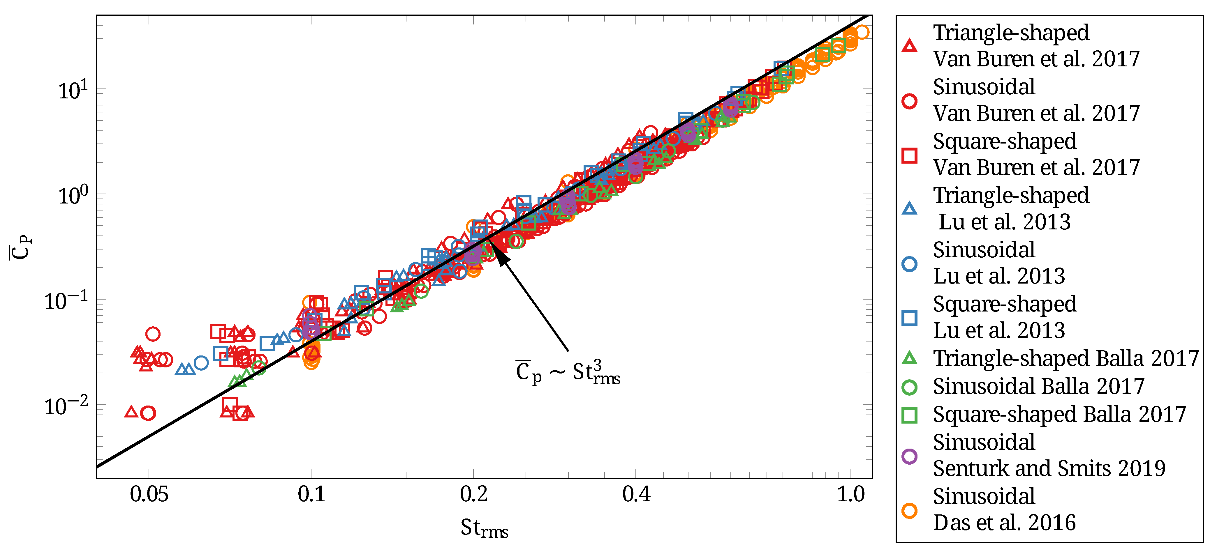
Besides the mean thrust coefficient, the power expended in generating the mean thrust is a crucial metric that eventually determines the feasibility of utilizing pitching foils for oscillatory thrust generation in artificial systems. The mean power expended in sustaining the pitching motion of the foil is directly linked to the cycle-average of the product of the moment experienced by the foil and the angular velocity of the foil. The corresponding mean power coefficient obtained by a normalization of the mean power with has been shown to exhibit a cubic dependence on Strouhal number in several previous works [8,11,20,25,36]. Given the outcome of our analysis of the mean thrust coefficient, it is then natural to expect that the pitching waveform induced variations in the power coefficient could likely be explained through a possibly simple relationship.
To test the foregoing expectation, we reexpressed the power coefficients from the previous works of Lu et al. [9], Van Burenin et al. [10], Balla [35] and Mackowski and Williamson [36] in terms of . The dependence that emerges from this reexpression is depicted in Figure 3, We find that the discrete data set from all the previous investigations [9,10,35,36,37] converge remarkably well to a cubic scaling law of the form . Thus, pitching waveform induced variations to the thrust generation characteristics and energetics of pitching foils are both quite well represented by .
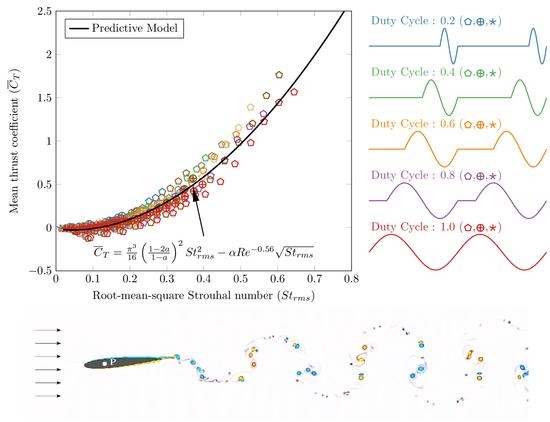
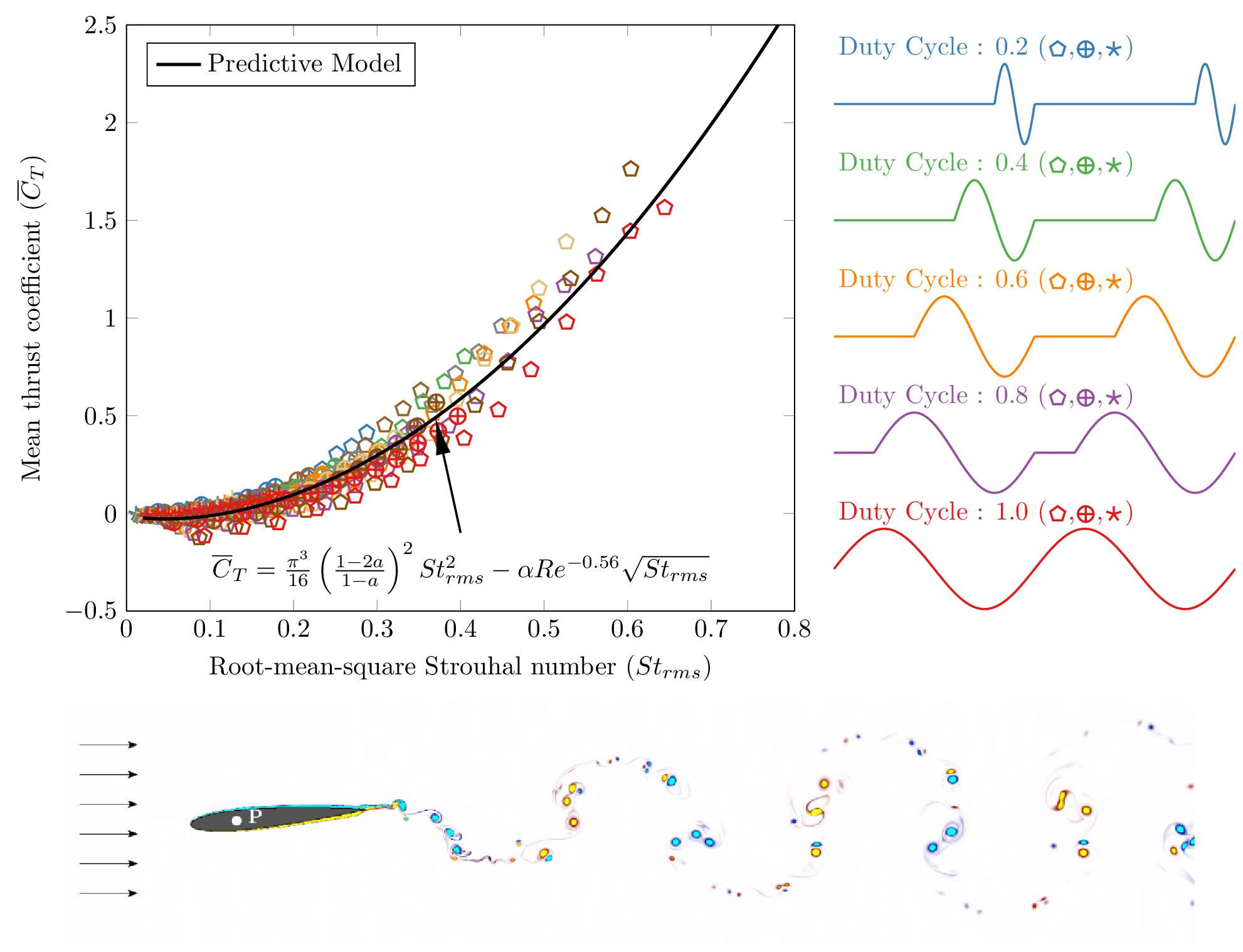
The interest in burst-and-coast mode of swimming [38] has inspired recent investigations into the thrust generation characteristics of foils undergoing intermittent oscillations [39,40]. An advantage of our analysis of foils undergoing prescribed multimodal rotational pitch is that it readily applies to intermittent pitching as well. To demonstrate this, in Figure 4 we compare our theoretical prediction (45) and the scaling law with the mean thrust and power coefficients for a tear drop shaped foil undergoing intermittent pitching as reported in Floryan et al. [40]. We find that for a wide range of pitching amplitudes and duty cycles, the discrete data set from Floryan et al. [40] is in near perfect agreement with our predictions. We may therefore conclude that the predictions from our theoretical analysis are applicable to intermittent pitching waveforms as well.
The discrete data set for the mean thrust and power coefficients associated with sinusoidal or triangle/square-shaped waveforms and intermittent pitching are thus in good agreement with our theoretical prediction (45) and the cubic power-law scaling . It is then reasonable to expect that the agreement will extend to the propulsive efficiency of thrust generation as well. The propulsive efficiency is well-known to be a concave function of the Strouhal number [8], specifically the propulsive efficiency is negative in the drag-producing regime of low Strouhal numbers and rises sharply attaining positive values for Strouhal numbers larger than a transition number of . Precisely at the transition Strouhal number the mean thrust vanishes identically () and a self-propelled state is established. For , increases attaining a maximum and then decreases with a further increase in . The maximum in the propulsive efficiency and the corresponding Strouhal number are of particular interest as they represent optimum conditions that lead to a maximization of energetic efficiency.
The ratio of the mean thrust coefficient given by the expression (45) and the mean power coefficient readily yields an estimate for the propulsive efficiency . By a maximization of this theoretical estimate with respect to we deduce the following for the maximum propulsive efficiency:
with the corresponding Strouhal number:
In Figure 5a we depict a comparison of the prediction (46) from our theoretical analysis with the maximum attainable propulsive efficiency deduced from previously reported experimental and computational investigations. We observe that the predicted from (46) compares favorably with the maximum propulsive efficiency reported in previous works [9,10,20,24,36,41] over the range . The corresponding Strouhal number at which the maximum in propulsive efficiency is attained is compared with the previous investigations in Figure 5b. The comparison also includes the drag-to-thrust transition Strouhal number . We find that like , both and compare favorably with the prior experimental and computational investigations over the range .
We note here that our predictions (46) and (47) rely intrinsically on the Bone-Lighthill boundary layer thinning hypothesis and a laminar boundary layer assumption which we used in arriving at the expression (44) for the cycle-averaged drag coefficient. At sufficiently large Reynolds numbers we expect a transition from a laminar to a turbulent boundary layer. The corresponding high-Reynolds-number drag coefficient is expected to exhibit weaker dependence on and eventually become independent of the Reynolds number. For such high Reynolds number scenarios we expect that a transition to a -independent will lead to a mean thrust that is independent of the Reynolds number. Consequently, at sufficiently high Reynolds number we expect a departure from the dependence indicated by the expressions (46) and (47) and anticipate , and to eventually become independent of the Reynolds number. This expectation is consistent with our earlier observations on a saturation in the peak propulsive efficiency of thrust generating foils that are pitched sinusoidally about their quarter chord [20]. The expectation is also consistent with the fact that the Strouhal number range over which undulatory natural swimmers cruise at high is particularly narrow and can essentially be viewed as being independent of the Reynolds number [3,6,8,42,43].
5. Conclusions
To conclude we presented a linearized potential flow theory and Bone-Lighthill boundary layer thinning hypothesis inspired model for prediction of thrust generation from foils that are pitched periodically in a possibly asymmetric and intermittent fashion about a fixed pivot point. The model allows for a rigorous identification of the various sources of the thrust, specifically, the added mass related contribution, the leading edge suction, and the quasi steady and wake contributions. In the specific limit of large reduced frequency, we showed that a dependence of the mean thrust coefficient on the Strouhal number based on the root mean square of the trailing edge velocity effectively accounted the pitching waveform induced variations. The mean thrust and power coefficients from several previously reported investigations on foils undergoing single-mode sinusoidal or multi-mode non-sinusoidal/ intermittent pitching showed a remarkable convergence with respect to the root mean square Strouhal number, in complete agreement with our model prediction. Over the range , the power law variation of the maximum achievable energetic efficiency and, the power laws for the drag-to-thrust transition Strouhal number and the Strouhal number for propulsive efficiency maximization were all in reasonable agreement with a range of prior computational and experimental investigations on sinusoidally, non-sinusoidally, and intermittently pitched foils. Our results highlight the utility of reduced-order predictive models in enabling a simple and insightful description of the oscillatory thrust generation characteristics of rotationally pitched foils.
Author Contributions
Conceptualization, A.D. and R.K.S.; formal analysis, A.D.; writing—draft preparation, review and editing, A.D., R.K.S. and R.N.G.; supervision, R.K.S. and R.N.G.; project administration, R.K.S. and R.N.G.; funding acquisition, R.K.S. and R.N.G. All authors have read and agreed to the published version of the manuscript.
Funding
We acknowledge support received from the National Supercomputing Mission of the Department of Science and Technology (runtime on cray XC-40 and Parampravega high performance computing systems housed in the Supercomputing Education and Research Center-Indian Institute of Science).
Data Availability Statement
The data that support the findings of this study are available within the article. Further data are available from the authors upon reasonable request.
Conflicts of Interest
The authors declare no conflict of interest.
References
- Kármán, T.v. Aerodynamics: Selected Topics in the Light of Their Historical Development; Cornell University Press: Ithaca, NY, USA, 1954. [Google Scholar]
- Anderson, J.D. Fundamentals of Aerodynamics; McGraw-Hill: New York, NY, USA, 2007. [Google Scholar]
- Gazzola, M.; Argentina, M.; Mahadevan, L. Scaling macroscopic aquatic locomotion. Nat. Phys. 2014, 10, 758–761. [Google Scholar] [CrossRef] [Green Version]
- Lucas, K.N.; Lauder, G.V.; Tytell, E.D. Airfoil-like mechanics generate thrust on the anterior body of swimming fishes. Proc. Natl. Acad. Sci. USA 2020, 117, 10585–110592. [Google Scholar] [CrossRef] [PubMed]
- Webb, P.W. Hydrodynamic and energetics of fish propulsion. Bull. Fish. Res. Board Can. 1975, 190, 1–156. [Google Scholar]
- Triantafyllou, M.S.; Hover, F.S.; Techet, A.H.; Yue, D.K.P. Review of Hydrodynamic Scaling Laws in Aquatic Locomotion and Fishlike Swimming. Appl. Mech. Rev. 2005, 58, 226–237. [Google Scholar] [CrossRef] [Green Version]
- Anderson, J.M.; Streitlien, K.; Barrett, D.S.; Triantafyllou, M.S. Oscillating foils of high propulsive efficiency. J. Fluid Mech. 1998, 360, 41–72. [Google Scholar] [CrossRef] [Green Version]
- Smits, A.J. Undulatory and oscillatory swimming. J. Fluid Mech. 2019, 874, P1. [Google Scholar] [CrossRef] [Green Version]
- Lu, K.; Xie, Y.; Zhang, D. Numerical study of large amplitude, nonsinusoidal motion and camber effects on pitching airfoil propulsion. J. Fluid. Struct. 2013, 36, 184–194. [Google Scholar] [CrossRef]
- Van Buren, T.; Floryan, D.; Quinn, D.; Smits, A.J. Nonsinusoidal gaits for unsteady propulsion. Phys. Rev. Fluids 2017, 2, 053101. [Google Scholar] [CrossRef]
- Das, A.; Shukla, R.K.; Govardhan, R.N. Foil locomotion through non-sinusoidal pitching motion. J. Fluid. Struct. 2019, 89, 191–202. [Google Scholar] [CrossRef]
- Garrick, I.E. Propulsion of a flapping and oscillating airfoil. NACA Tech. Rep. 1937, 567, 419–427. [Google Scholar]
- Kármán, T.v.; Sears, W.R. Airfoil theory for non-uniform motion. J. Aeronaut. Sci. 1938, 5, 379–390. [Google Scholar] [CrossRef]
- Lighthill, M.J. Large-amplitude elongated-body theory of fish locomotion. Proc. R. Soc. Lond. B 1971, 179, 125–138. [Google Scholar]
- Ehrenstein, U.; Eloy, C. Skin friction on a moving wall and its implications for swimming animals. J. Fluid Mech. 2013, 718, 321–346. [Google Scholar] [CrossRef] [Green Version]
- Ehrenstein, U.; Marquillie, M.; Eloy, C. Skin friction on a flapping plate in uniform flow. Philos. Trans. R. Soc. A 2014, 372, 20130345. [Google Scholar] [CrossRef] [PubMed] [Green Version]
- Moored, K.W.; Quinn, D.B. Inviscid scaling laws of a self-propelled pitching airfoil. AIAA J. 2019, 57, 3686–3700. [Google Scholar] [CrossRef] [Green Version]
- Fernandez-Feria, R.; Sanmiguel-Rojas, E. Comparison of aerodynamic models for two-dimensional pitching foils with experimental data. Phys. Fluids 2019, 31, 057104. [Google Scholar] [CrossRef]
- Alam, M.M.; Muhammad, Z. Dynamics of flow around a pitching hydrofoil. J. Fluids Struct. 2020, 99, 103151. [Google Scholar] [CrossRef]
- Das, A.; Shukla, R.K.; Govardhan, R.N. Existence of a sharp transition in the peak propulsive efficiency of a low-Re pitching foil. J. Fluid Mech. 2016, 800, 307–326. [Google Scholar] [CrossRef]
- Godoy-Diana, R.; Thiria, B. On the diverse roles of fluid dynamic drag in animal swimming and flying. J. R. Soc. Interface 2018, 15, 20170715. [Google Scholar] [CrossRef]
- Floryan, D.; Van Buren, T.; Smits, A.J. Efficient Cruising for Swimming and Flying Animals Is Dictated by Fluid Drag. Proc. Natl Acad. Sci. USA 2018, 115, 8116–8118. [Google Scholar] [CrossRef] [Green Version]
- Floryan, D.; Van Buren, T.; Rowley, C.W.; Smits, A.J. Scaling the propulsive performance of heaving and pitching foils. J. Fluid Mech. 2017, 822, 386–397. [Google Scholar] [CrossRef] [Green Version]
- Senturk, U.; Smits, A.J. Reynolds number scaling of the propulsive performance of a pitching airfoil. AIAA J. 2019, 57, 2663–2669. [Google Scholar] [CrossRef]
- Das, A.; Shukla, R.K.; Govardhan, R.N. Contrasting thrust generation mechanics and energetics of flapping foil locomotory states characterized by a unified scaling. J. Fluid Mech. 2022, 930. [Google Scholar] [CrossRef]
- Jones, M.A. The separated flow of an inviscid fluid around a moving flat plate. J. Fluid Mech. 2003, 496, 405–441. [Google Scholar] [CrossRef]
- Shukla, R.K.; Eldredge, J.D. An inviscid model for vortex shedding from a deforming body. Theor. Comp. Fluid Dyn. 2007, 21, 343–368. [Google Scholar] [CrossRef] [Green Version]
- Alben, S. Simulating the dynamics of flexible bodies and vortex sheets. J. Comput. Phys. 2009, 228, 2587–2603. [Google Scholar] [CrossRef]
- Eldredge, J.D. Mathematical Modeling of Unsteady Inviscid Flows; Springer: Berlin/Heidelberg, Germany, 2019. [Google Scholar]
- Theodorsen, T. General theory of aerodynamic instability and the mechanism of flutter. NACA Tech. Rep. 1935, 496. [Google Scholar]
- Fernandez-Feria, R. Linearized propulsion theory of flapping airfoils revisited. Phys. Rev. Fluids 2016, 1, 084502. [Google Scholar] [CrossRef]
- Fernandez-Feria, R. Note on optimum propulsion of heaving and pitching airfoils from linear potential theory. J. Fluid Mech. 2017, 826, 781–796. [Google Scholar] [CrossRef]
- Abramowitz, M.; Stegun, I. Handbook of Mathematical Functions; Dover: Downers Grove, IL, USA, 1968. [Google Scholar]
- Hover, F.S.; Haugsdal, O.; Triantafyllou, M.S. Effect of angle of attack profiles in flapping foil propulsion. J. Fluids Struct. 2004, 19, 37–47. [Google Scholar] [CrossRef] [Green Version]
- Balla, A. Measurements of Propulsive Performance of Oscillating Foils. Master’s Thesis, Indian Institute of Science, Bangalore, India, 2017. [Google Scholar]
- Mackowski, A.W.; Williamson, C.H.K. Direct measurement of thrust and efficiency of an airfoil undergoing pure pitching. J. Fluid Mech. 2015, 765, 524–543. [Google Scholar] [CrossRef]
- Bohl, D.G.; Koochesfahani, M.M. MTV measurements of the vortical field in the wake of an airfoil oscillating at high reduced frequency. J. Fluid Mech. 2009, 620, 63–88. [Google Scholar] [CrossRef] [Green Version]
- Videler, J.J.; Weihs, D. Energetic advantages of burst-and-coast swimming of fish at high speeds. J. Exp. Biol. 1982, 97, 169–178. [Google Scholar] [CrossRef] [PubMed]
- Akoz, E.; Moored, K.W. Unsteady propulsion by an intermittent swimming gait. J. Fluid Mech. 2018, 834, 149–172. [Google Scholar] [CrossRef] [Green Version]
- Floryan, D.; Van Buren, T.; Smits, A.J. Forces and energetics of intermittent swimming. Acta Mech. Sinica 2017, 33, 725–732. [Google Scholar] [CrossRef] [Green Version]
- Xiao, Q.; Liao, W. Numerical study of asymmetric effect on a pitching foil. Int. J. Mod. Phys. C 2009, 20, 1663–1680. [Google Scholar] [CrossRef]
- Taylor, G.K.; Nudds, R.L.; Thomas, A.L.R. Flying and swimming animals cruise at a Strouhal number tuned for high power efficiency. Nature 2003, 425, 707–711. [Google Scholar] [CrossRef]
- Eloy, C. Optimal strouhal number for swimming animals. J. Fluids Struct. 2012, 30, 205–218. [Google Scholar] [CrossRef] [Green Version]
Figure 1.
Schematic depicting the uniform flow past a foil that undergoes an oscillatory rotational pitch about the pivot point P. The foil’s angular position is indicated with . The length coordinate s ranges from to b from the leading to the trailing edge of the foil, where . The coloured contours illustrate the instantaneous vorticity distribution for a prototypical flow that ensues from the oscillatory motion of a foil pitched sinusoidally about its quarter chord with an angular amplitude at a frequency that leads to and . Here, blue and yellow contours indicating negatively and positively signed vorticity levels.

Figure 2.
Mean thrust coefficient as a function of the root mean square Strouhal number . Differentially shaped symbols represent single-mode sinusoidal (◯), and multimodal triangle-shaped (∆) and square-shaped (☐) pitching waveforms. Solid lines represent predictions from the Reynolds number and pivot location specific - relation (45). Color variations are used to distinguish between cases associated with distinct and . In panel (a) theoretical predictions are compared with two-dimensional computational results of Lu et al. [9] for a NACA0012 foil pitched about its quarter chord at = 13,500 and at three distinct pitching amplitudes. Panels (b–f) depict similar comparisons with previously published results. Panel (b) depicts comparison with the experimental results of Van Buren et al. [10] for a tear drop shaped foil pitched about its leading edge at and seven distinct pitching amplitudes, panel (c) with the experimental results of Balla [35] for a NACA0012 foil pitched about its quarter chord at a fixed angular amplitude of and seven distinct , and panel (d) with the experimental results of Mackowski and Williamson [36] at = 16,600 and Bohl and Koochesfahani [37] at =12,600 for a NACA0012 foil pitched sinsusoidally about its quarter chord. Panels (e,f) compare the theoretical prediction (45) with the computational results of Senturk and Smits [24] and Das et al. [20], respectively, for a NACA0012 foil pitched sinsusoidally about its quarter chord over a range of and a fixed angular amplitude ( and in Senturk and Smits [24] and Das et al. [20], respectively).


Figure 3.
Mean power coefficient as a function of the root mean square Strouhal number for periodically pitched foils. The symbols used to distinguish between different cases are exactly the same as in Figure 2. The solid line represents a cubic power law fit through the discrete data set.
Figure 3.
Mean power coefficient as a function of the root mean square Strouhal number for periodically pitched foils. The symbols used to distinguish between different cases are exactly the same as in Figure 2. The solid line represents a cubic power law fit through the discrete data set.

Figure 4.
Mean thrust and power coefficients and as a function of the root mean square Strouhal number for foils undergoing prescribed intermittent rotational pitch with duty cycles () ranging from to and angular amplitudes , and . Discrete points are taken from the experimental investigation of Floryan et al. [40] for a tear drop shaped foil pitched about its leading edge at . Distinct symbols and colors are used to distinguish between cases associated with distinct and , respectively. The solid line in the left panel (a) represents the theoretical prediction (45) while the one in the right panel (b) is a cubic power law fit.

Figure 5.
Maximum propulsive efficiency (panel (a)) and, the corresponding Strouhal number at which maximum efficiency is achieved and the drag-to-thrust transition Strouhal number (panel (b)) as a function of . Discrete points are taken from the previous experimental and computational investigations as indicated in the legend above. The symbols (◊), (◯) and (∆) represent , and , respectively, with the colors used to distinguish the discrete dataset from each of the prior experimental and computational investigations. Multiple similarly colored and shaped symbols are used to represent discrete dataset corresponding to a similar but distinct . Bohl and Koochesfahani [37] focus on drag-to-thrust transition and their reported dataset does not include mean thrust or efficiency. Xiao and Liao [41] target thrust maximization and the Strouhal number range investigated in their computational work is beyond the Strouhal number for the drag-to-thrust transition. The solid line in the left panel (a) represents the theoretical prediction (46). The solid and dashed lines in the right panel (b) are obtained from the theoretical predictions (47). Note that theoretical predictions are expected to hold only over a limited range for which the boundary layer remains laminar and therefore, the solid and the dashed lines extend only upto a finite .

Publisher’s Note: MDPI stays neutral with regard to jurisdictional claims in published maps and institutional affiliations. |
© 2022 by the authors. Licensee MDPI, Basel, Switzerland. This article is an open access article distributed under the terms and conditions of the Creative Commons Attribution (CC BY) license (https://creativecommons.org/licenses/by/4.0/).
Share and Cite
MDPI and ACS Style
Das, A.; Shukla, R.K.; Govardhan, R.N. Universal Scaling Laws for Propulsive Performance of Thrust Producing Foils Undergoing Continuous or Intermittent Pitching. Fluids 2022, 7, 142. https://doi.org/10.3390/fluids7040142
AMA Style
Das A, Shukla RK, Govardhan RN. Universal Scaling Laws for Propulsive Performance of Thrust Producing Foils Undergoing Continuous or Intermittent Pitching. Fluids. 2022; 7(4):142. https://doi.org/10.3390/fluids7040142
Chicago/Turabian StyleDas, Anil, Ratnesh K. Shukla, and Raghuraman N. Govardhan. 2022. "Universal Scaling Laws for Propulsive Performance of Thrust Producing Foils Undergoing Continuous or Intermittent Pitching" Fluids 7, no. 4: 142. https://doi.org/10.3390/fluids7040142