MAC Layer Protocols for Internet of Things: A Survey
by
 , , and
Luiz Oliveira
1, 
Joel J. P. C. Rodrigues
1,2,3,* ,
,
Sergei A. Kozlov
3,
Ricardo A. L. Rabêlo
4 and
Victor Hugo C. de Albuquerque
5
1
National Institute of Telecommunications (Inatel), Santa Rita do Sapucaí MG 37540-000, Brazil
2
Instituto de Telecomunicações, 1049-001 Lisboa, Portugal
3
International Institute of Photonics and Optoinformatics, ITMO University, 197101 Saint Petersburg, Russia
4
Department of Computing (DC), Graduate Program in Computer Science (PPGCC), Federal University of Piaui (UFPI), Ministro Petronio Portela Campus, Teresina 64049-550, Piaui, Brazil
5
Graduate Program in Applied Informatics, University of Fortaleza (UNIFOR), Fortaleza CE 60811-905, Brazil
*
Author to whom correspondence should be addressed.
Future Internet 2019, 11(1), 16; https://doi.org/10.3390/fi11010016
Submission received: 27 November 2018
/
Revised: 17 December 2018
/
Accepted: 18 December 2018
/
Published: 14 January 2019
(This article belongs to the Special Issue 10th Anniversary Feature Papers)
Abstract
:Due to the wide variety of uses and the diversity of features required to meet an application, Internet of Things (IoT) technologies are moving forward at a strong pace to meet this demand while at the same time trying to meet the time-to-market of these applications. The characteristics required by applications, such as coverage area, scalability, transmission data rate, and applicability, refer to the Physical and Medium Access Control (MAC) layer designs of protocols. This paper presents a deep study of medium access control (MAC) layer protocols that are used in IoT with a detailed description of such protocols grouped (by short and long distance coverage). For short range coverage protocols, the following are considered: Radio Frequency Identification (RFID), Near Field Communication (NFC), Bluetooth IEEE 802.15.1, Bluetooth Low Energy, IEEE 802.15.4, Wireless Highway Addressable Remote Transducer Protocol (Wireless-HART), Z-Wave, Weightless, and IEEE 802.11 a/b/g/n/ah. For the long range group, Narrow Band IoT (NB-IoT), Long Term Evolution (LTE) CAT-0, LTE CAT-M, LTE CAT-N, Long Range Protocol (LoRa), and SigFox protocols are studied. A comparative study is performed for each group of protocols in order to provide insights and a reference study for IoT applications, considering their characteristics, limitations, and behavior. Open research issues on the topic are also identified.
1. Introduction
Most Internet of Things (IoT) technology features are defined by the protocols used to design the technology for specific applications. Features such as network topology, power consumption, transmission power efficiency, and delays are important issues in the definition or choice for using a certain technology for a particular solution. Beyond medium access control (MAC) layer characteristics, its main functions can be cited as frame boundary delimitation, frame synchronization, handling of source and destination addresses, detection of physical medium transmission errors, and collision avoidance [1]. Medium access techniques, data rates, communication mode between devices, transmission range, power consumption, and others are all examples of characteristics derived from the development and deployment of each protocol. Therefore, the study of MAC layer protocols can show how to design a suitable technological solution for an application.
Based on its own needs, IoT applications may require the adaptation of the existing network protocols so that they can meet the requirements of IoT applications. Protocols may need to be adjusted, evolved or developed to meet the IoT applications that demand different performance characteristics such as far-reaching, reliable and robust low power transmission techniques. According to requirements, it is possible to classify and point out the main MAC layer protocols suitable to attend a service characteristic. The already existing definitions such as Wireless Body Area Networks (WBAN), Wireless Personal Area Networks (WPAN), Low Rate Wireless Personal Area Networks (LR-WPAN), and Wireless Local Area Networks (WLAN) can be classified as short distance protocols due to their maximum range of 1 km. While Wide Area Networks (WAN) and Low Power Wide Area Networks (LP-WAN) protocols can be used as references for long range classification due their ranges of more than 1 km. WAN protocols are commonly designed for user content and the media. Some of their evolution such as Long Term Evolution (LTE) CAT-M have enhancements to support some IoT requirements such as lower power consumption. LP-WAN protocols came to attend long range with low power consumption but enough data rate to attend IoT services requirements.
The purpose of this paper is to present a deep study of short and long distance MAC layer protocols used by IoT solutions, addressing the MAC layer characteristics that defines each protocol behavior and applicability. This approach arises MAC layer comparisons in several aspects, including distance coverage, transmission data rate, transmission efficiency, communication mechanisms, MAC and PHY (Physical) layer control techniques, both in terms of use of resources and efficiency aspects of packet processing among other performance metrics. This study also gives inputs to obtain reference and comparison parameters in the design or choice of a technology to better serve a certain application, with specific characteristics. Thus, the main contributions of this paper are the following:
- Deep review of the state of the art and classification of short and long distance IoT MAC layer protocols;
- Comparison study of the protocols considering their specifications and characteristics;
- Identification of open research issues and lessons learned on the topic.
The rest of this paper is organized as follows. Section 2 elaborates on a detailed study of short range coverage MAC layer protocols. A deep study of long range MAC layer protocols is present in Section 3. Section 4 brings a discussion about short and long distance IoT MAC layer protocols arising from their main characteristics through comparison identifying a set of important open research issues. Section 5 gives a summary of the lessons learned is exposed and, finally, Section 6 concludes the study.
2. Short Range MAC Layer Protocols
Short range coverage medium access control (MAC) protocols are defined by the Institute of Electrical and Electronics Engineers (IEEE) as Wireless Personal Area Networks (WPAN), which is the network established between elements that surround the human body. WPAN communication technologies differ from other conventional wireless network technologies. These networks call for easy connectivity in order to reach personal wearable or hand-held devices. Moreover, WPAN requires power efficiency, small size, low cost and maybe most importantly easy to use devices [2,3].
Short-distance technologies such as near field communication (NFC) and radio frequency identification (RFID) are technologies that fit into this study context due to their usage with differentiated mechanisms for the physical and linking layers. Thus, their characteristics are less critical when compared to the IEEE 802.15.6 standard [4], which is dedicated to wireless body area networks (WBAN). Such networks have different scenarios and prerequisites that are very different from those that are supported by the networks of things. Body sensor networks have very critical requirements when compared to the networks of things such as WBANs. These network characteristics should achieve a maximum latency of 125 ms to attend medical applications, they cannot surpass 250 ms to be applied to non-medical applications, and their jitter must be lower than 50 ms. Low power consumption, automatic connection and disconnection of new elements in the network, mixed typologies, low overhead and other characteristics are examples of the high critical parameters in WBANs [5,6,7].
There are technologies that use differentiated methods to treat their PHY and MAC layers as Long Term Evolution (LTE) mobile networks. These technologies offer differentiated techniques of connection establishment methods, communication controls, and physical access controls, among others. Thus, it becomes difficult to compare some protocols with the standard offered by the open systems interconnection (OSI) reference model. The physical medium approach and connection establishment methods, communication controls, and other mechanisms are dedicated to systems that cannot be directly compared to the OSI. Another difficulty of establishing a fair comparison with other protocols that follow the OSI reference model is that these protocols are, in the majority of applications, dedicated to the point-to-point communication or large data volumes. These characteristics release them from the need for more elaborate connection establishment methods and data transfer control systems [8].
2.1. Radio Frequency Identification (RFID)
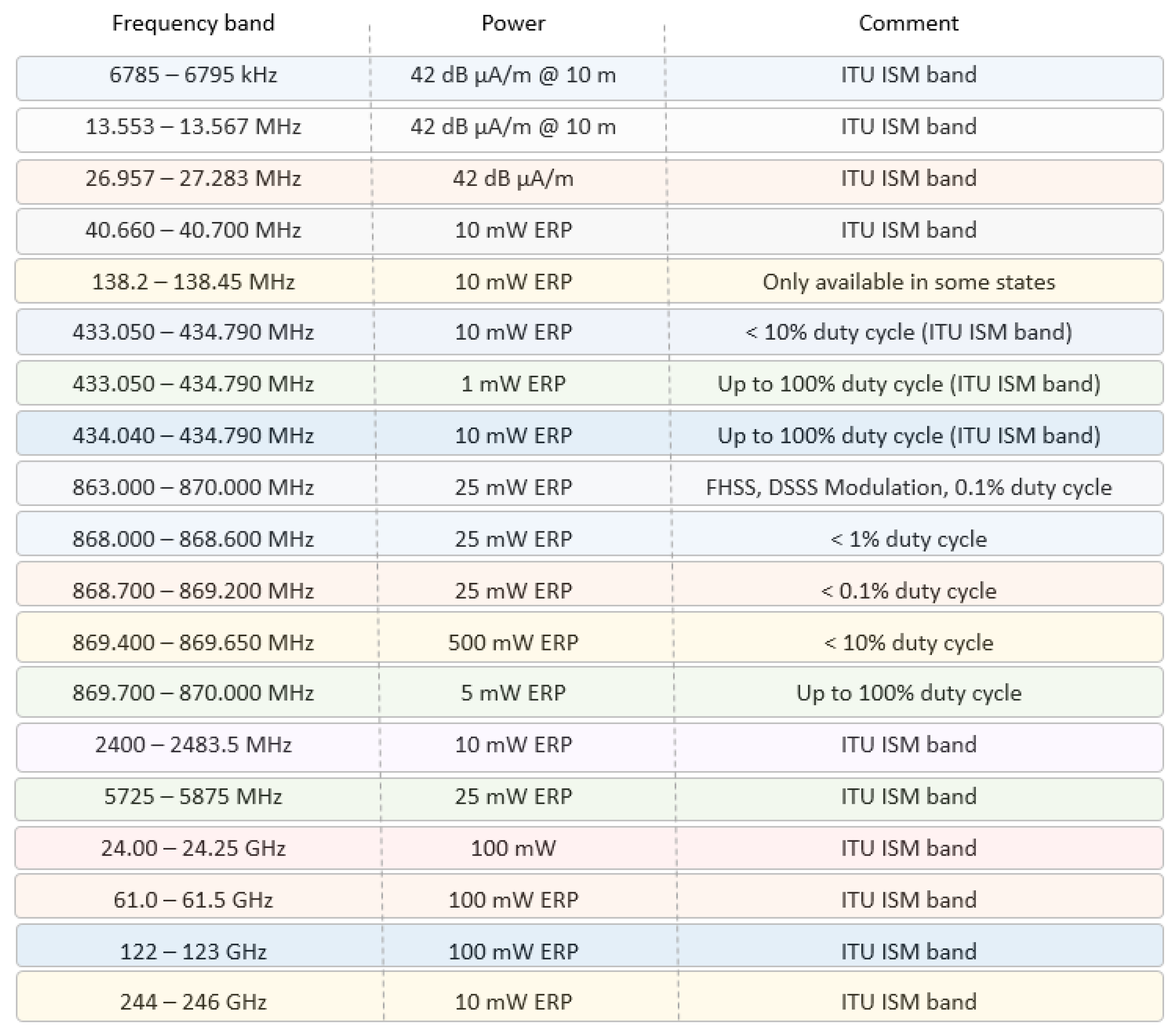
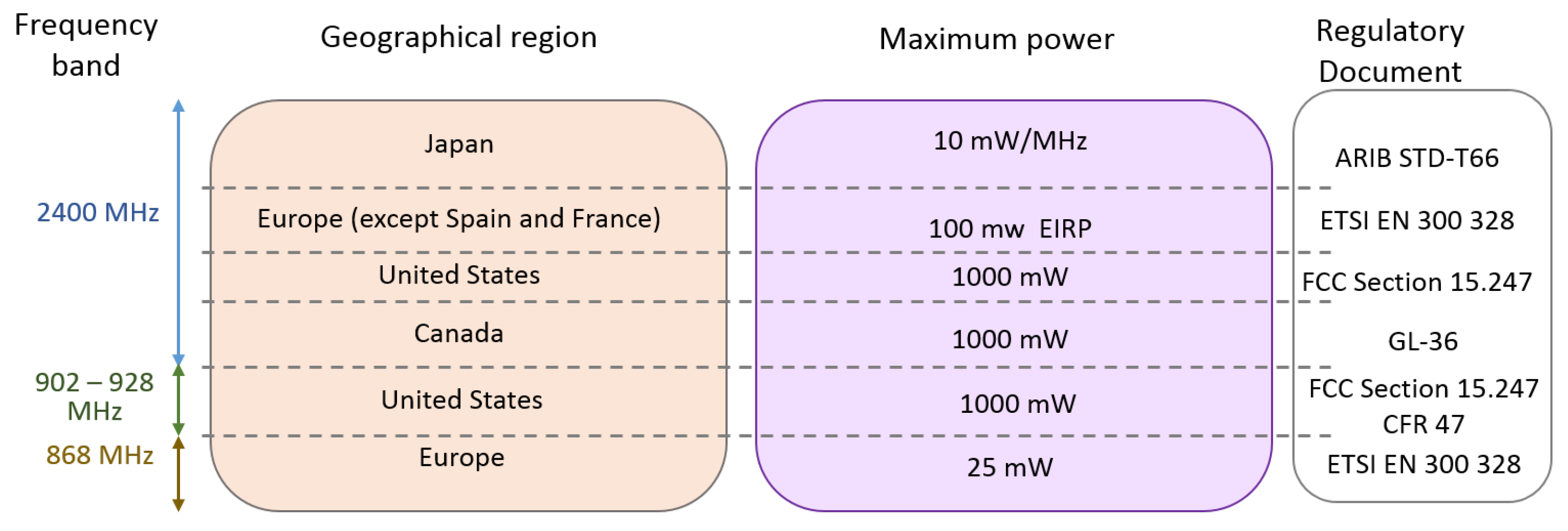
Radio Frequency Identification (RFID) refers to a set of technologies that are aimed at identifying and recognizing elements (tags). An RFID system is basically composed of two types of devices: the identified devices (tags) and the device identifiers or readers. Tagged devices are triggered by RF (Radio Frequency) waves emitted by the reader devices and reply its identification (ID) tags. Readers handle data exchange between them. When necessary, readers send RF pulses interrogating the tags in the area. Tags reply to this question by submitting their tag IDs. Different classifications of RFID systems can be provided according to operating frequency, radio interface, communication range, tag autonomy (completely passive, semi-passive, active), and different standards have been ratified. Evolution of smart UHF (Ultra High Frequencies) RFID tags with embedded sensors and miniaturization of readers promotes this technology for high pervasive IoT ecosystems [9]. Figure 1 presents a brief summary of operation frequencies, transmission power level, and European regulation comments.
The various devices identified by radio frequencies (RFIDs) such as wristbands, clothing, footwear, and others are a combination of a small microchip and an antenna integrated into a single casing uniquely identified electronically. When readers send their interrogation radio frequency pulse, tags transmit their identification information to the reader devices using radio frequencies. This transmission takes place depending on the proximity of the tag to the reader device, even though it does not have line of sight (LOS). The transmission range will depend on the class of device used. Transmissions occur from the low frequency (LF) bands at 124–135 KHz to ultra-high frequency band (UHF). There are three classes of RFID devices [11] as follows:
- PRAT—Passive Reader Active Tag. The reader is passive and receives data from a battery-powered tag. The transmission range can reach up to 500 m depending on some characteristics of the system and transmission frequency used.
- ARPT—Active Reader Passive Tag. The reader is active and the identified tags are passive and powered by the energy harvested from the electromagnetic waves present in the air. In general, this power source can be a beacon transmitted by the reader to feed the tags and it receives back the transmission of the tag data. This is the most commonly used class.
- ARAT—Active Reader Active Tag. This class is where both the reader and the tags are powered by external power sources, but the tags only transmit their data when requested by the readers.
There is a certain variety of standards for RFID systems. ISO (International Organization for Standardization)/IEC (International Electrotechnical Commission) 14443 [12] are the entities responsible for defining the behavior and properties of smart cards [13,14]. The standard defines the nomenclature of the ’reader device’ as the Proximity Coupling Device (PCD) and the Tag Identified (TI) or, ‘the object to be identified’, is defined as the Proximity Integrated Circuit Card (PICC).
One of the most commonly used identification standards in this case is the electronic product code (EPC) which contains a 96-bit structure in a string data format. This structure consists of eight initial bits that identify the protocol version followed by 28 bits representing the organization entity that produced such a label. The following 24 bits identify the type or class of the element and the remaining 36 bits are the unique serial identification of each particular element. These last two fields are used by vendors to assign identities to their devices [15]. Differentiated information such as Uniform Resource Locators (URLs) or some other more current pattern can also be used as identifiers as long as they meet the standardized format [16,17].
2.2. Near Field Communication (NFC)
For short-range communications, NFC technology is important since its massive adoption by mobile device vendors has popularized its use, making it accessible to the public for applications such as label reading or even peer-to-peer data exchange. The devices involved exchange information between themselves as a machine-to-machine connection mode [18]. Standardization of NFC is assisted by the International Organization for Standardization (ISO) conjoined with the International Electrotechnical Commission (IEC) and NFC Forum.
Near Field Communication is a short range transmission technology that uses low-power transmission links that, differently from Bluetooth, do not require pairing for transmission. Just bringing one device close enough to the other allows communication. This feature forces the user of the device to be handling it during use. As the facility of the device works only with is owner, it is a manner to ensure the safe security of the technology usage. Its operation is comparable to RFID technology because NFC devices can act as both a reader and a tag. The communication is performed in active or passive mode, operating in the 13.56 MHz band. A typical range from another device is about 0.2 m and it is sensitive to near fields or even the touch, its transmission rate can reach 424 Kbps. In the passive mode communication, the active device initiates the connection by transmitting a carrier wave that activates the passive device. Thus, the passive device makes use of this carrier to modulate and transmit its data. In the active mode of communication, both the communication initiating device and the target device communicate by generating their own carrier waves. These devices need to be powered by external power sources.
NFC tags and readers can operate in three different modes: card emulation, reader/writer and peer to peer (or point to point). In NFC Card Emulation mode, usually the active device reads the passive device tag types. Both of them can be active or passive devices. In the NFC Peer to Peer (Point to Point) mode standardized according to the ISO/IEC 18092 [19], two nodes are connected to each other by a peer to peer or ad hoc mode in order to exchange data [20]. The massive deployment of NFC came to join the use of RFID as complementary technology and, as a consequence, are becoming important technological solutions for pay-machines, smart objects, smart wearables, and many other devices. These technologies are commonly used in applications, such as tracking objects and people, to offer personalized information and services such as in e-health applications. This scenario brings a new concept of “thing” or object socialization. In this concept, the link between the ported object and the person who carries it establishes a unique co-ownership and relationship. This relationship is capable of influencing decisions in human environment interactions and raising the level of the consciousness of the object [21,22].
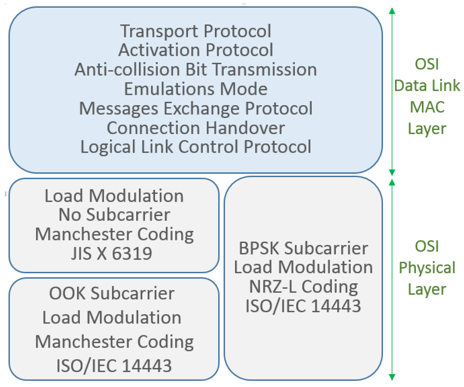
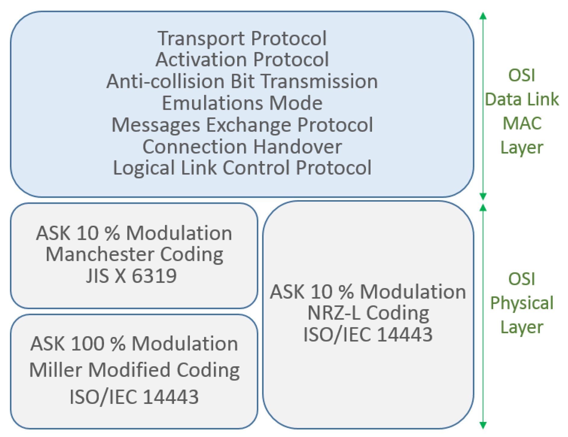
On the physical layer of NFC, RF communication data rates are 106, 212, 424 as well as 848 Kbps depending on the combination of modulation and code techniques used. The available modulation schemes are ASK (Amplitude Shift Keying) using 10% or 100% modulation depth, Non-Return-to-Zero Level (NRZ-L), Binary Phase Shift Keying (BPSK) and Manchester or Modified Miller coding are used for the data transfer. The International Organization for Standardization (ISO), International Electrotechnical Commission (IEC), and Federal Communications Commission (FCC) regulate the transmission power to be 20 or 23 dBm according to region [23,24,25,26]. The NFC MAC layer is also responsible for connection handling, message exchange, emulation modes, anti-collision bit transmission, activation procedures, data transport, and others. Figure 2 and Figure 3 illustrate these functionalities [18].
2.3. Bluetooth IEEE 802.15.1
WPAN IEEE 802.15.1 also called the Bluetooth Basic Rate (BR) is a global 2.4 GHz specification working with short-range wireless networking. It covers the versions v1.0, 1.0B with voice dialing, call mute, last number redial and a 10 m range as the main facilities and a v1.2 with adaptive frequency hopping added. Versions v2.0+Enhanced Data Rates (EDR) and v2.1+EDR added more capabilities such as improved resistance to radio frequency interference as well as improving indoor coverage and LOS range to 100 m. Fast transmission speeds and low power consumption mechanisms were also increased on the v2.0+EDR and v2.1+EDR versions. Version v2.1 counts on a sniff subtracting function that results in less transmissions do access the medium and so reducing interference.
The evolution follows with v3.0 receiving enhanced power control to quickly adapt to the changing path loss of the new 5 GHz transmission frequency bands. Version 4.0 increased the modulation index, resulting in less energy used during transmission but still presented a certain medium consumption to complete the receiving process. Version 4.1 shows better alignment on pico-nets timing when the transmission suffers interference. In Version 4.2, the low energy is reinforced with the adoption of longer packet transmissions. This reduces the quantity of packets transmitted for the same information size, using a packet length extension technique. The present version of Bluetooth v5.0 has some improvements regarding transmission and receiving processes. The Bluetooth v5.0 improvements include slot availability mask, which allows the alignment of pico-nets timing with nearby LTE bands, an increased coding gain, increased symbol rate and a better channel selection algorithm.
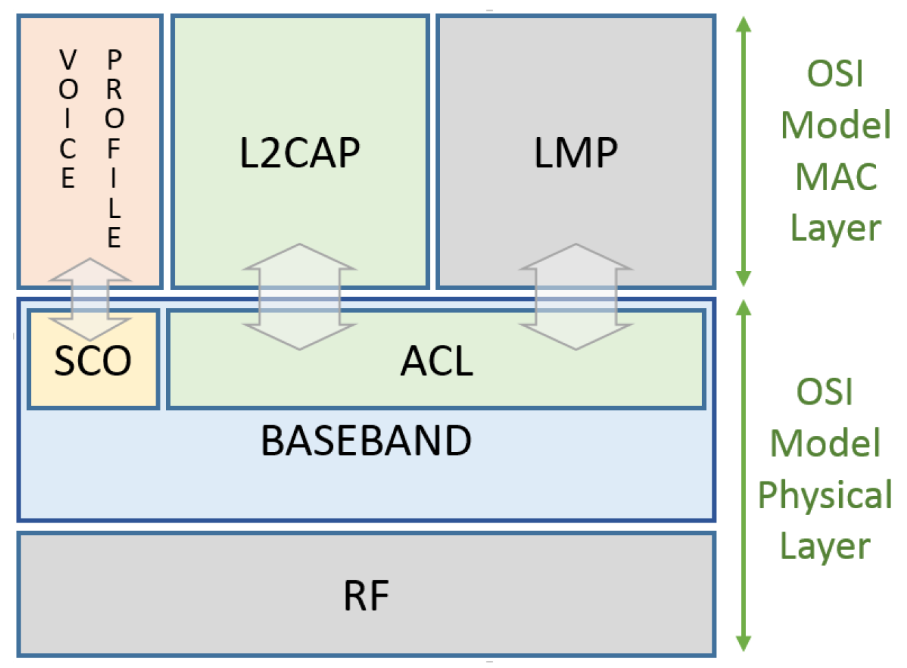
The IEEE 802.15.1 MAC layer is composed of Logical Link Control, the Adaptation Protocol (L2CAP) layer, the Link Manager Protocol (LMP) layer, and the Base-band or simply the Physical layer. The Bluetooth MAC layer handles the communication types that can be asynchronous connectionless (ACL) or synchronous connection-oriented communication (SCO). Figure 4 shows the relationship between the Open Systems Interconnection model (OSI), the seven-layer model and the IEEE 802.15.1 standard.
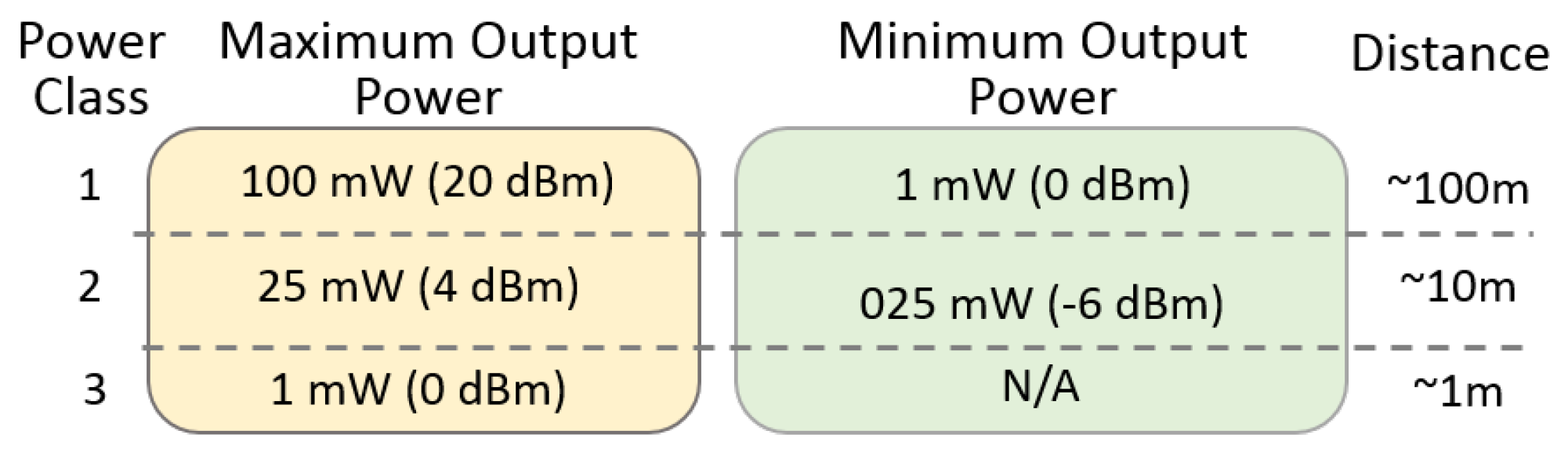
The Base-band Layer defined by the IEEE 802.15.1 standard operates in the 2.4-GHz Industrial Scientific and Medical (ISM) band using a short-range radio link and a fast frequency-hopping (FFH) transceiver. The Radio and the Base-band sub-layers define the Bluetooth physical layer. The Radio layer provides the physical links among Bluetooth devices with 79 different Radio Frequency (RF) channels spaced of 1 MHz, using a frequency hopping spread spectrum (FHSS) transmission technique. This FHSS technique increases the robustness of the link due to its capability to reduce the interference of nearby systems that may operate in the same frequency range. A Time Division Duplex (TDD) transmission scheme is specified to divide the channel into time slots of 625 s each, corresponding to a different hop frequency, simulating full-duplex communication in the same transmission channel. The radio link which reaches up to 100 m with LOS is obtained using the nominal power according to its power class and the irradiating system used. Three output power classes divide the Bluetooth Basis Rate protocol devices. Each class is characterized by a maximum power and a minimum output power, and, based on these values, the distance within which the device can communicate is defined according to the list in Figure 5.
The main roles of the Bluetooth MAC layer are to set-up the physical connections between the master and slaves; send and receive packets along the physical channels; synchronize the network devices with the master clock and manage the different devices for power saving states [27].
In summary, the base-band functionalities are clock synchronism, management timers, addressing and assessment devices, physical channel handling, channel hop selection, physical link supervision, logical transport management, logical link management, formatting and ordering bits, bit-stream processing, error checking, error correction, definition of ARQ (Automatic Repeat Request) schemes, managing link controller operations, support for general audio recommendations, audio level control, audio paths, frequency mask, and others.
A Link Management Protocol is a control protocol responsible to establish base-band and physical layer links. Functions such as connection establishment and release, among others, are Link Management (LM) features acquired by LMP utilization that handles a Synchronous Connection-Oriented (SCO) link, and an Asynchronous Connectionless Link (ACL). A SCO physical link establishment is a symmetric point-to-point connection between the master and a specific slave. It is used to deliver delay-sensitive traffic, such as voice service, and works as a circuit-switched connection between the master and the slave. The ACL link is a point (master) to multi-point (slaves) in a pico-net domain and works as a packet-switched connection, which considers the Bluetooth devices that support point-to-multi-point connections. To ensure the integrity of the data and to guarantee a reliable delivery of the data, ACL uses a fast Automatic Repeat Request scheme.
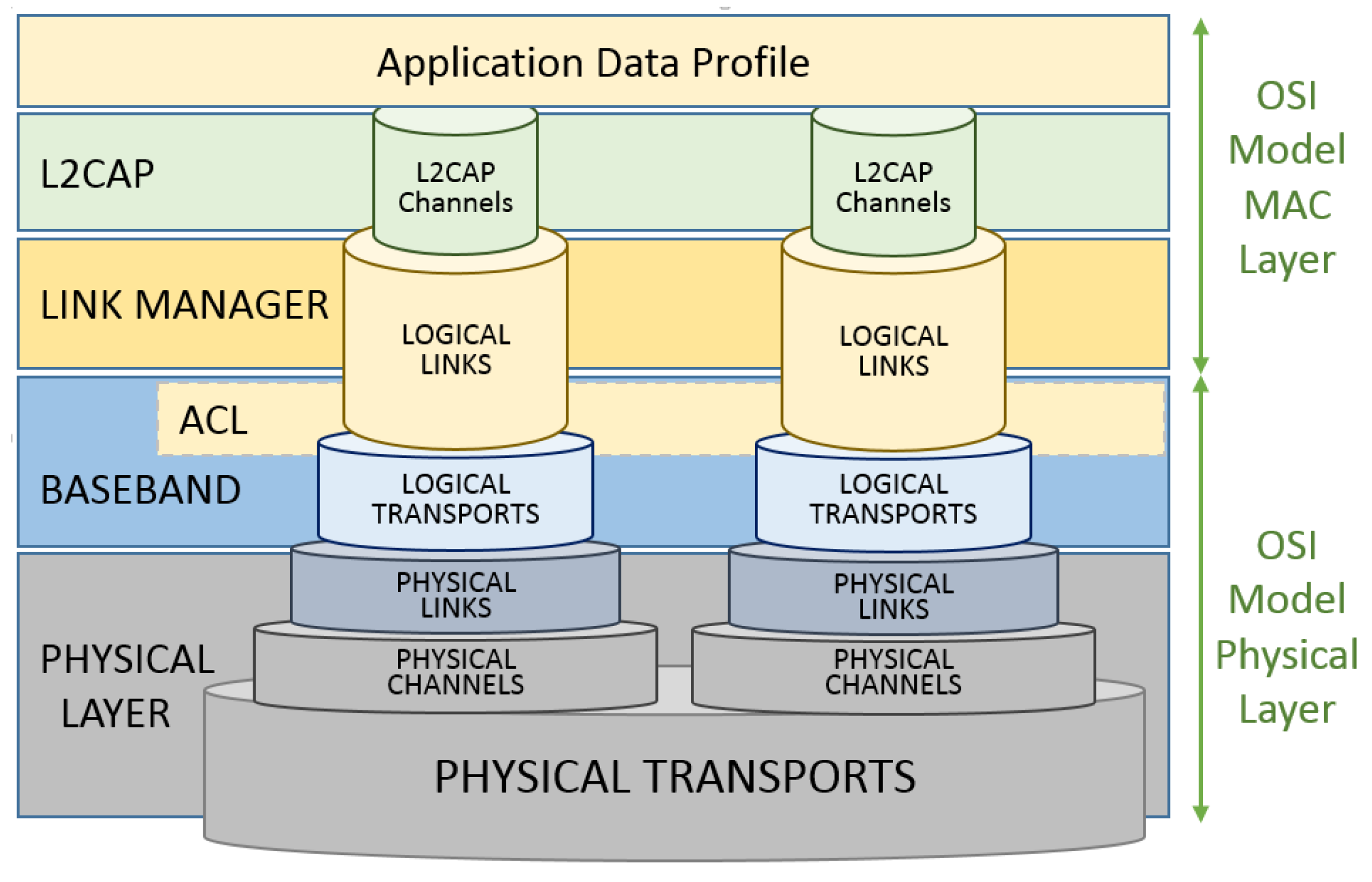
The Logical Link Control and Adaptation Protocol (L2CAP) layer is a channel-based abstraction between the base-band and service application layer. The L2CAP layer handles segmentation and reassembly of application data, and multiplexing and de-multiplexing of multiple channels over a shared logical link [28]. The L2CAP layer is responsible for handling the size adjustment of the maximum transmission unit (MTU) when the application layer data is larger than the MTU of the base-band layer. The L2CAP layer can segment the application data in order to seize the maximum MTU transmitted based on the size of the MTUs received by the application This feature reduces the overhead on the information sent thus, improving the efficiency. Endpoint peer devices receive a Channel Identifier (CID) used for signaling purposes associated to its connections, for ACL and SCO data communication between L2CAP devices. Some CIDs are reserved for the L2CAP layer as a logical channel required to meet Bluetooth standards and is reserved for signaling purposes. Connectionless channels support ‘group’ or multi-point communication, while connection-oriented channels are dedicated to peer-to-peer connections only [29]. Figure 6 elucidates the data channelization, links and transport structure.
Bluetooth relies on the contention-free token-based multi-access networks as logical topology. End point devices are mentioned as slaves. A cluster of up to seven slave devices can be attached to a master device, in order to have access to the channel, composing a pico-net cellular topology. The master is responsible to manage the polling process messages to authorize a slave device to access the channel and transmit its data. These features increase the range to more than 100 m with a LOS path in an outdoor environment also increasing its indoor environment range to about 40 m. The utilization of beacons as sense mechanisms and the larger message capacity of 255 bytes improves the communication performance.
Data rates have a theoretical value of 2 Mbps but with a practical recommendation of 1.6 Mbps considering overheads. A pico-net data rate can reach up to 1 Mbps, which represents the channel capacity not considering the overhead introduced by the adopted access control techniques and polling scheme. The coverage areas of the pico-nets can be overlapped forming a scatter-net topology when at least one unit exchanges data with more than one master. This allows a slave to be active in more than one pico-net at the same time but can be managed by only one master element. When using a time-multiplexing mode, a slave can communicate with more than one pico-net but only in different time periods. This is due to the necessity to change its synchronization parameters or in order to listen to different channels. A size of a pico-net is limited to just one master and up to seven active slave stations [27]. The conventional ad hoc topology is also used.
2.4. Bluetooth Low Energy
Being part of the Bluetooth v4.0 standard adopted in 2010-06-30, Bluetooth Low Energy (BLE) is also known as Smart Bluetooth. BLE is an IEEE 802.15.1 variation with better and more suitable capacities for low power applications than the classic Bluetooth Basic Rate. Devices that demand communication with both standards of Bluetooth are required to implement and support both protocol stacks due the incompatibilities among them. Star is the only topology accepted by BLE due the standard definition that does not permit physical link connections among slave devices. Any data exchanged between two slave devices shall pass through the unique master and a slave device may not be connected to two master units at the same time. These premises define the formation of a BLE star pico-net [30].
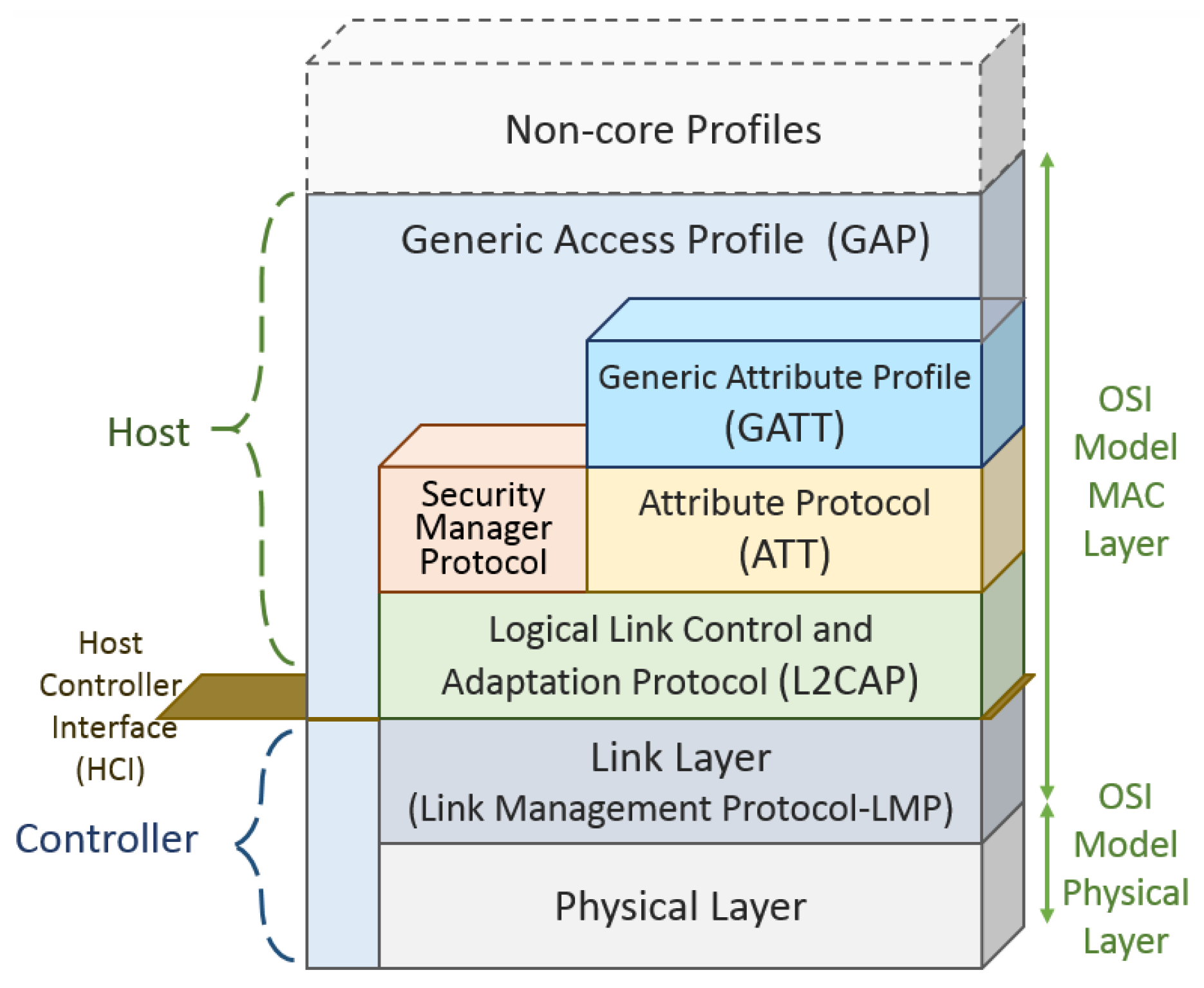
Using a similar protocol stack as classic Bluetooth, the differences between them starts above the L2CAP layer. Above the L2CAP layer, BLE is the application layer that uses a set of functionalities, which are not present in the classic Bluetooth specifications. These functionalities are the Attribute Protocol (ATT), the Generic Attribute Profile (GATT), the Security Manager Protocol (SMP) and the Generic Access Profile (GAP). Figure 7 depicts the BLE protocol stack.
The two main roles of BLE are: controller and host. BLE differs from the classical Bluetooth in the controller stack that defines the association methods of the devices. A slave can belong to only one pico-net during an association lifetime, and is synchronized with only one master element.
A Host Controller Interface (HCI) is a communication standard applied between the slave and controller. In the Bluetooth Basic Rate, 79 channels are used with a 1 MHz bandwidth to reduce interference with adjacent channels. In Bluetooth Low Energy, the channels are defined in the 2.400–2.4835 GHz band with a 2 MHz guard band. To achieve scalability, the master device controls the number of hosts associated with it by adjusting the value of the connection interval (ConnInterval parameter) between hosts and controllers.
Link layer manages events generated by the hosts, at determined time intervals, using the advertising channels. Bidirectional data flow is obtained with a connection between elements, when slaves advertising packets are received by master elements. The energy save handling done at MAC layer can put the slaves in a sleeping mode by default and waking them periodically through a Time Division Multiple Access (TDMA) scheme. In the classic Bluetooth basic protocol, this layer a stop-and-wait flow control mechanism is used to provide error recovery capabilities. At BLE, the L2CAP is an adaption of the classic Bluetooth basic protocol stack but optimized and simplified to receive the application layers designed for low energy platforms. Data exchange between the application layer and link layer are also done by L2CAP using no retransmission techniques or flow control mechanisms as used on the classic Bluetooth. Not using retransmission or flow control mechanisms (present in the classic Bluetooth) and segmentation and reassembly capabilities, the Packet Data Units (PDU) (limited to 23 bytes in BLE) received by the application layer is delivered ready to fit the maximum size of the L2CAP payload.
When two devices are connected under a server and client association architecture, the server needs to maintain a set of attributes. The Attribute Protocol (ATT) handles the attributes of this connection like the definition of data structure used to store the information managed by the Generic Attribute Profile (GATT) that works on top of the ATT. GATT defines the client or server functionalities of a connection and this association is independent of the master or slave roles. The attributes of the server need to be accessed by the client through the requests sent, which trigger the response messages of the server. It is also possible for a server to send to a client, unsolicited messages like notifications that do not need any confirmation message to be sent by the client. A server is also required to send indication messages, which need confirmation messages to be sent by the client. The slave sends requests for responses and indications prior to transactions confirmation following a stop-and-wait scheme. Slaves can either write attributes values at the master.
A framework defined by GATT performs the role of discovery services using the ATT attributes, and allows exchange of characteristics between devices interconnected. An attribute carries a set of characteristics that includes a value and properties of the parameter monitored by the device. For example, a humidity sensor needs humidity characteristics and attributes to describe this sensor, and to store its measurements. Thus, this sensor needs a further attribute to specify the measurement units.
Creating specific profiles with the Low Energy Bluetooth standard takes place in the Generic Attribute Profile (GATT). GATT uses the Attribute Protocol (ATT) protocol in addition to the lower stack protocols, in order to introduce the subdivision of retained server attributes into services and features. Services can contain a set of features, which can include a single value (accessible from the client) and other numerical data that describe such features. Among the assignments of GAP profile specifications are: device role rights, discovery devices and services, as well as establishing connections and security. A new profile based on the existing profile requirements can be created following a profile hierarchy. The interoperability of different devices can be handled through application profiles.
Bluetooth is designed to offer a low-cost alternative to Wi-Fi at the expense of the transmission range. Its transmission range is considerably shorter (up to 100 m LOS) and data rate does not exceed 721.2 Kbps in the classic Bluetooth Basic Rate version and can reach 3 Mbps with the Enhanced Data Rate feature. BLE operates at 1Mbps rate on its physical layer, while its application layer can handle only 236.7 Kbps.
In Bluetooth Low Energy, there are no subdivisions in power classes but only the maximum and minimum output power values of the transmitter are provided. Only an approximate value of the maximum reachable distance can be predicted. The low power required for transmission is the main feature of the Bluetooth Low Energy standard and this result is due to enhancements made on the classic version. These enhancements include reduced frequency band and shorter PDU packets [31].
An energy evaluation is offered at [32] using CC2640 radio chipset consumption reference measurements. The comparison is made when operating on 0 dBm transmission power by gathering the main characteristics of Bluetooth and BLE.
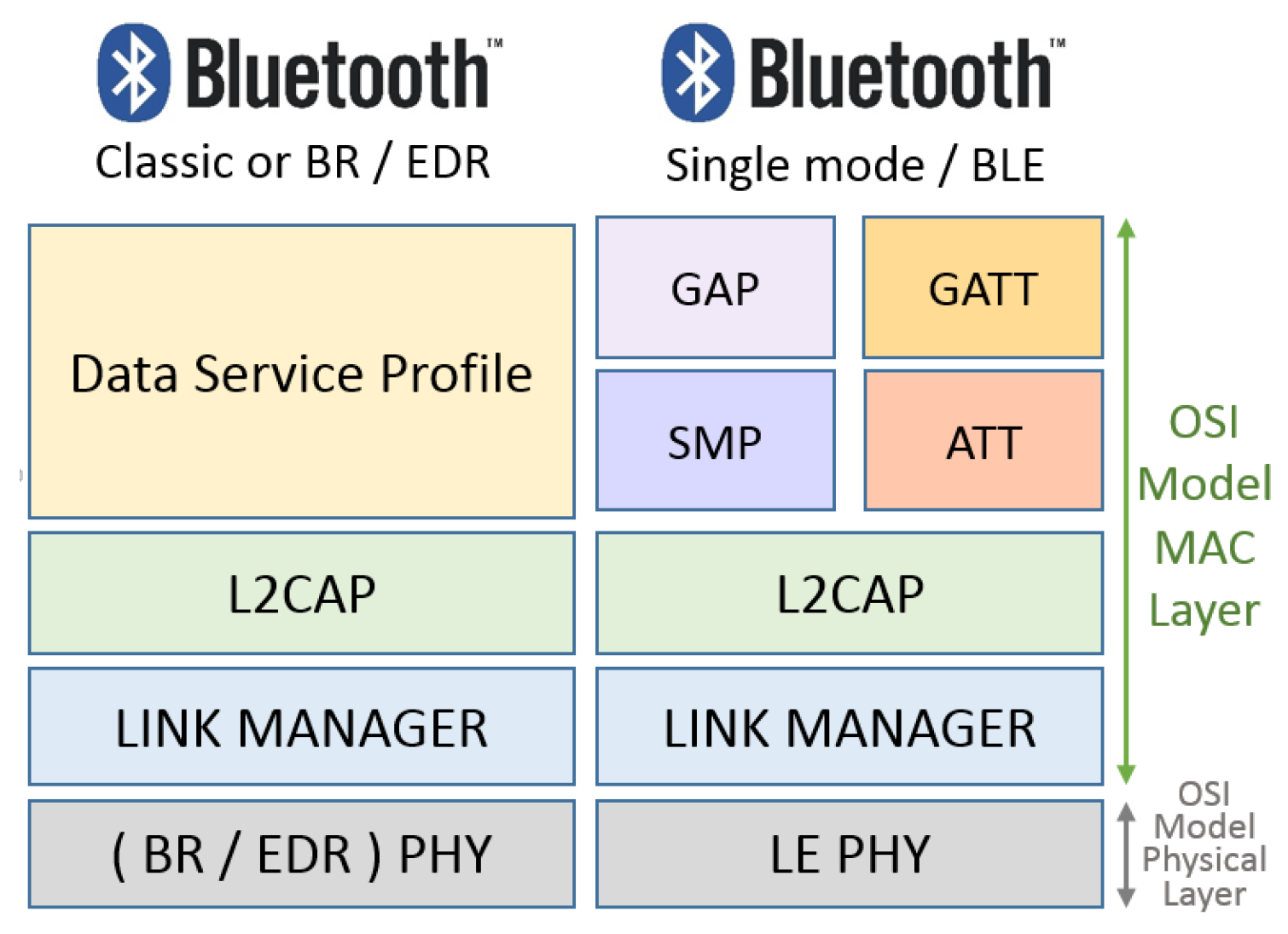
Bluetooth v5.0 has no functional block included in its first and second layers when compared to versions v4.0, v4.1, and v4.2. A representation of the inter-layer communication structure and the relationship with Bluetooth layers of different Bluetooth versions can be seen in Figure 8. Device-to-device file transfers, wireless speakers, wireless headsets, and Body Sensor Networks are often enabled with Bluetooth versions.
Finally, some characteristics of the Bluetooth BR and BLE technologies are summarized in Figure 9. This figure allows the comparison of their differences according to the PHY and MAC layer characteristics.
2.5. IEEE 802.15.4
IEEE 802.15.4 is a subgroup of features that refers to physical and medium access control layers that can support ZigBee and 6LoWPAN upper. IEEE 802.15.4 focuses on physical and data link layer specifications while ZigBee Alliance aims to provide the upper characteristics [33]. It is a standard that defines PHY and MAC layers for personal area networks that demand low rate and low cost applications. This also called a LR-WPAN protocol and has some advantages. Among them are a simple and flexible protocol stack, low cost, low energy consumption, short-range operation, reliable data transfer, and ease of operation [34]. These features are more important when operating in the Personal Operating Space (POS) also defined as Personal Area Network (PAN) that involves the human body.
An IEEE 802.15.4 device address can be a short 16-bit or 64-bit address [35]. In addition, IEEE 802.15.4 uses a Direct Sequence Spread Spectrum (DSSS) access mode and operates on 2450 MHz, 915 MHz, and 868 MHz ISM bands working with 16 channels, 10 channels, and one channel, respectively. The main limitations of the radio interfaces working in the ISM frequency band are the small sizes and the narrow bandwidths. Small sizes and narrow bandwidths consequently cause a reduction in output power transmission. With these radio interface characteristics, it is possible to obtain from 20 to 250 Kbps shared among all the nodes using the same channel [36,37].
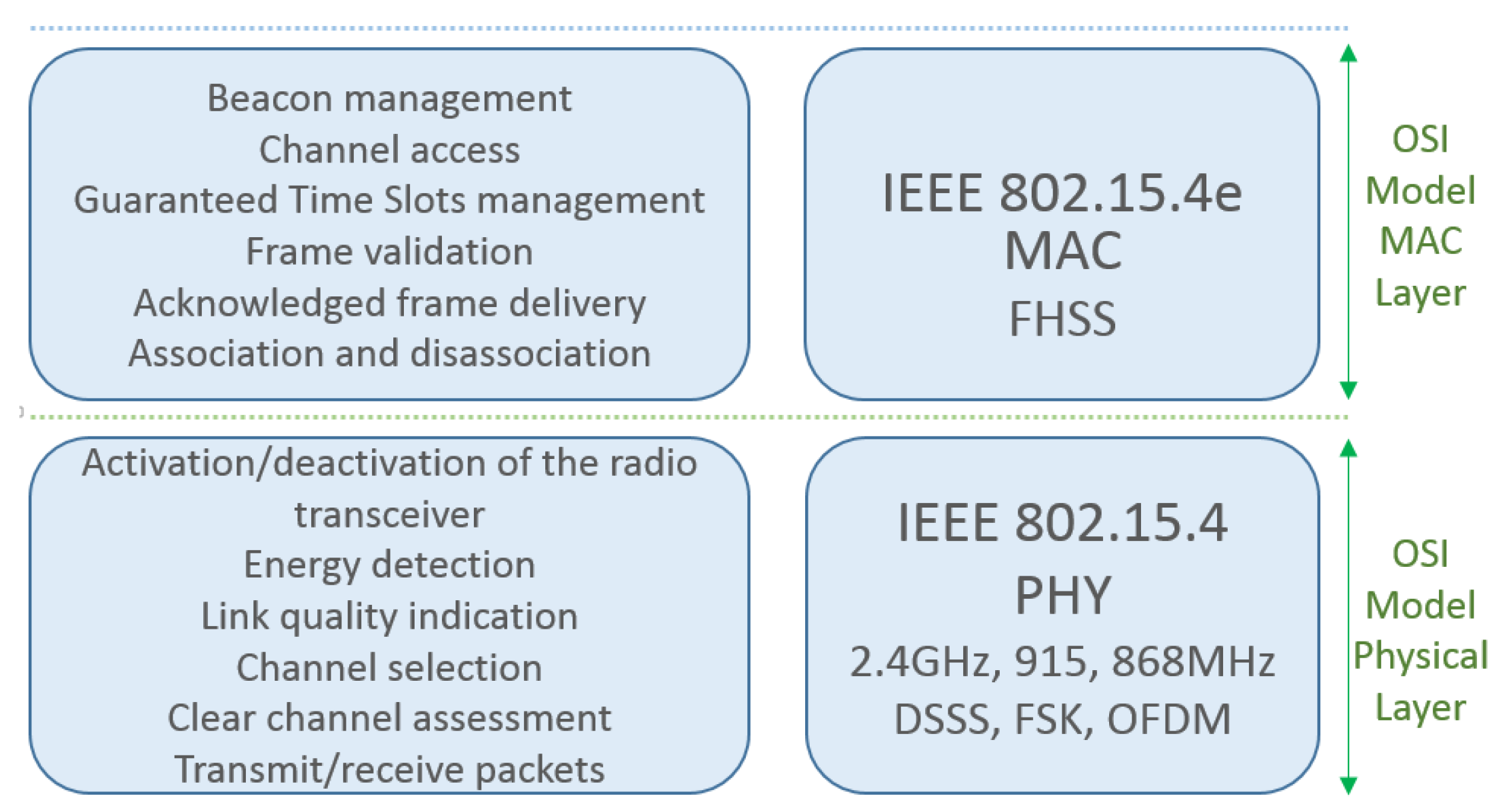
The physical layer provides an interface between the physical data service and the PHY management service accessed through service access points (SAPs). This layer is also responsible for activation, and deactivation of the radio transceiver, energy detection (ED) within the current channel, link quality indication (LQI) for received packets, clear channel assessment (CCA) for carrier sense multiple access with collision avoidance (CSMA-CA), channel frequency selection, and data transmission and reception. The energy saving aspects of IEEE 802.15.4 are mainly addressed to this layer by the ED, LQI and CCA functionalities [35]. According to the PHY layer specifications, and following the spectrum utilization of each region, the distances between the nodes based on IEEE 802.15.4 can be up to 100 m. This range depends on propagation environment obstacles and the maximum transmission power levels defined by the IEEE 802.15.4 standard, illustrated in Figure 10 [3,38].
The IEEE 802.15.4 MAC layer provides access to the physical channel for all upper layers, providing two kinds of services: the MAC data service and the MAC management service. MAC data and MAC management are services that are also provided to other layers enabling them to access the PHY layer resources. The standard defines two different methods of channel access that are a beacon enabled (BE) mode and a non-beacon-enabled (NBE) mode. The MAC sub-layer, which is responsible for beacon management, is also responsible for channel access, Guaranteed Time Slots (GTS) management, frame validation, delivered frame acknowledgement, and association/disassociation activities [33].
An IEEE 802.2 Logical Link Control (LLC) can access the IEEE 802.15.4 MAC sub-layer through the Service Specific Convergence Sub-layer (SSCS). The SSCS IEEE 802.2 convergence sub-layer exists in a conceptual perspective, on the top of the MCPS (MAC Common Part Sub-layer). SSCS provides a link between the IEEE 802.2 LLC sub-layer and the IEEE 802.15.4 MCPS in the data service plane through the MCPS-SAP (MCPS-Service Access Point). On the management plane, driving the layer management functions, the MMLE (MAC sub-layer Management Entity) provides the service functions assembling capability through an interface between the SSCS and PHY. MMLE is also responsible for maintaining a PIB (PAN Information Base) which contains the data base of the managed objects belonging to the MAC sub-layer [3].
The IEEE 802.15.4 BE and NBE operational modes have being strongly investigated over recent years. Thus, some limitations have been addressed and the most important ones are the unbounded delay, low communication efficiency, low interference robustness, and/or fading and main powered relay nodes [39,40,41,42,43].
The IEEE 802.15.4 Task Group 4e was chartered to define a MAC amendment to the standard 802.15.4-2006 in order to evolve and add important functions to the 802.15.4-206 MAC protocol to enhance MAC to PHY functionalities interaction [44]. IEEE 802.15.4e supports five new categories of MAC enhancements also called MAC behaviors: Time Slotted Channel Hopping (TSCH), Deterministic and Synchronous Multi-channel Extension (DSME), Low Latency Deterministic Network (LLDN), Asynchronous Multi-channel Adaptation (AMCA), and Radio Frequency Blink (BLINK) [45]. Some general enhancements were also included as follows: Low Energy (LE), Information Elements (IE), Enhanced Beacons (EB), Multipurpose Frame, MAC Performance Metrics, and Fast Association (FastA) mechanism [46]. Figure 11 compares IEEE 802.15.4 stack with the OSI reference model.
The use of multipurpose sensor networks becomes as a natural network environment with a focus on how to reduce the implementation of the operation costs through the reuse of resources. Ordinary traffic generated by regular applications such as environmental monitoring will not require the same treatment as the traffic response required for applications that use information queries time sensitive [47] characteristics. A heterogeneous traffic coexistence, with different QoS (Quality of Service) requirements is not handled well by IEEE 802.15.4. One option to improve QoS is the adoption of multiple transmission queues in both 802.15.4 and 802.15.4e considering the urgency level of the different traffic. This process separates the different QoS traffic in different classes and handles them on four transport queues with differential treatments [36,48].
Mobility can be treatable by IEEE 802.15.4 but can hardly degrade the network performance [49] and happens when an orphan device that loses its coordinator association attempts to synchronize with network coordinators. The IEEE 802.15.4 terminal uses the common transmission channel to search for coordinators. On the topology aspect, the coordinators that belong to the same Personal Area Network Identification (PANId) are connected to a Super Coordinator that can handle the device mobility from one coordinator to another. It is important to point out that, during this re-association, the service data are interrupted. Some authors enlarged their visions beyond IEEE 802.15.4 limits suggesting inter-technology mobility. For example, to allow a mobile node to move through the cells in a various cluster tree network. Coordinators have both IEEE 802.15.4 wireless and wired connections” [50] to expand the mobility domain. Energy performance is boosted by channel hopping based on multi-channel support. The development of IEEE 802.15.4 is a joint work between IEEE and ZigBee Alliance. The stack consists of layers one and two of the IEEE 802.15.4 standard as the basis for other protocols such as ZigBee itself, 6LoWPAN, Thread, and ISA100 [51,52]. Due the fact that these protocols are derived from the IEEE 802.15.4 PHY and MAC layers, they belong to the network layer and are out of context for this comparison.
2.6. Wireless-HART
Wireless-HART (Highway Addressable Remote Transducer Protocol) is a variation of IEEE 802.15.4 design to work essentially as a centralized wireless network. IEEE 802.15.4 is designed to meet the requirements of industrial wireless applications with hard timing parameter restrictions, critically security issues, and severity on obstacle interferences. The Wireless-HART protocol has the same specifications as IEEE 802.15.4 PHY, but develops its own MAC layer based on the TDMA technique.
Using Bluetooth, there is no guarantee to delay values on an end-to-end wireless communication. The absence of a hopping channel technique and a quasi-static star Bluetooth topology works against its scalability. These characteristics make them inappropriate to be used in industrial scenarios. Wireless HART comes as a solution for process control applications through the effort of some industrial organizations such as International Society of Automation 100 (ISA 100) [52], HART [53], Wireless Industrial Networking Alliance (WINA) [54] and ZigBee Alliance [55] to attend their specific requirements ratified by the HART Communication Foundation in 2007.
Using the IEEE 802.15.4 PHY layer, Wireless-HART operates in the license-free ISM of 2.4–2.4835 GHz with 2 MHz bandwidth of each one of the 16 channels. The channels are numbered from 11 to 26 with a gap of 5 MHz between IEEE 802.11b/g adjacent channels, delivering up to 250 Kbps. Wireless-HART uses its own Time Division Multiplex Access (TDMA) on the MAC layer including the 10 ms synchronized time slot features. These characteristics allow the messages routing through a network topology obstacle and interference. This is possible due to the use of self-organizing and self-healing mesh networking techniques supported by the network layer. Even being essentially a centralized wireless network, Wireless-HART uses a network manager in its stack in order to provide routing and communication schedules. This can guarantee network performance and satisfy the wireless industrial applications. The focus of Wireless-HART is communication on a one-hop level and the network layer has its responsibility to the network devices vicinity allocation [3,56,57,58].
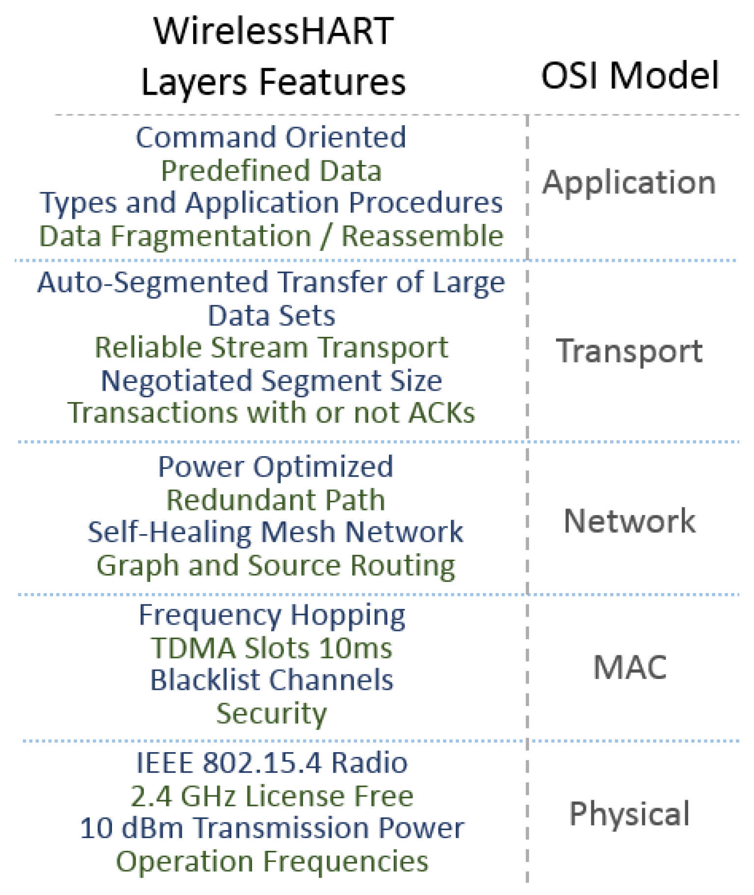
Differing from IEEE 802.15.4, Wireless-HART uses time-synchronized the TDMA technique combined with frequency hopping on its MAC layer, thus allowing multiple devices to transmit data at the same time along different channels. During the joining process of the devices onto networks, the network manager distributes the communication links and the channel hop patterns to the devices. It also manages the enabling or disabling of the use of channels that are frequently affected by considerable interference levels, calling this feature channels blacklist, wHart-n-802-15-4e, petersen2011wirelesshart. The eight types of devices defined on Wireless-HART are: routers, gateways, adapters, network managers, network security devices, access points and field devices on a mesh topology. All of them support the implementation of features to attend network creation, maintenance issues, data and signaling routing capability, and a minimum of reliability. A comparison between the OSI reference model and Wireless-HART protocol layers and its main features is shown in Figure 12.
Another addressable characteristic of Wireless-HART is the information blocks that each network device maintains on its memory. The information of neighbor nodes and the next reachable device is called a neighbor information block. The connection with the network layer is made through the block information, adding data to the network layer routing table. Working with TDMA as a medium access technique, the network devices have very stringent timing requirements to accomplish network synchronization premises. This happens because synchronization occurs both in the joining process and in normal operations [58].
2.7. Z-Wave
Z-Wave was developed and is overseen by the company Zensys to provide wireless communication between devices with a focus on residential automation. Monitoring and controlling of lighting, ambient temperature and security through sensors and actuators by tablets, smartphones or computers are some applications in its portfolio. Z-Wave devices are arranged in mesh network topology. They can send and receive messages from any device that is connected to the network [59,60].
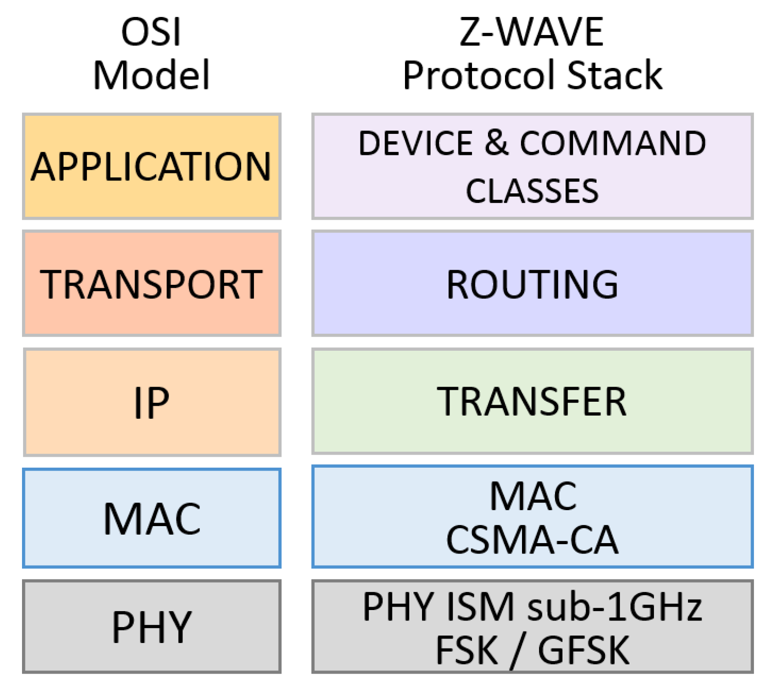
The protocol is a proprietary standard based on the ITU G.9959 specification that operates in the Industrial, Scientific, and Medical (ISM) radio frequency band. Z-Wave transmits on 868.42 MHz (Europe) and 908.42 MHz (United States) frequencies working with FSK and Gaussian Fase Shift Keying (GFSK) modulations. With low transmission rates of 9.6 Kbps, 40 Kbps and 100 Kbps, it employs symmetric AES-128 encryption. The MAC layer uses the CSMA-CA technique for a medium access control technique and, based on ITU G.9959, has the following characteristics: a capacity of 232 unique network identifiers that allows the same quantity of nodes joying the network; collision avoidance mechanism; back-off time when collision occurs; reliability guaranteed by receiving acknowledgments; frame validation and retransmission mechanisms. A power saving mechanism is achieved due to a sleep mode with a dedicated wake-up pattern [61,62]. Figure 13 depicts the Z-Wave protocol stack.
The Z-Wave basic device classes are the following: Portable Controller, Static Controller, Slave, and Slave with Routing Capabilities. Different classes provide the device with a certain role in the Z-Wave network. Inside a Basic Class, Generic and Specific device classes are used to achieve the wanted functionality in the control network. In the Z-Wave protocol, the unique identification of the devices is used through a 32-bit ID. This ID value cannot be changed as it is written in the device chipset by the device manufacturer. A Z-Wave network has only one primary controller device at a time. Each of the 232 nodes of this network can also be a repeater for forwarding data to its neighbors, mediating a connection. Battery-powered nodes do not enjoy this facility. In an environment with a certain level of device drift or even when a device is removed from the network for some reason, the network topology may change. Changing network topology can lead to problems in packet forwarding and packet routing in the network. To minimize this effect, routing tables should be kept up-to-date, optimized and any new topology detected; Z-Wave supports the discovery and suitability of the new network topology. This is possible by keeping the routing table up-to-date on each device and showing all neighboring devices [61,63]. When a node changes its position or is removed from the network, a topology failure can start an automatic topology and healing procedure to detect the new topology and define the best routes to update the routing tables. This mechanism is subjected to unauthorized modification of routing table attacks by rouge nodes [64].
The transfer (or transport) layer management functions are: communication between two neighbor nodes, packet acknowledgment, low power network nodes awake (Beaming), and packet origin authentication. This layer controls the Beam frames used to wake-up battery powered Z-Wave devices, as each primary controller device of a cluster can handle up to 232 nodes. All nodes can act as a packet repeater, except those devices that are batteries powered. This is Z-Wave mesh topology formed [65].
Z-Wave data security is based on AES and on the cipher block chaining message authentication code (CBC-MAC). However, standards and rules for command classes, device types and timers are missing. These characteristics are only acquired in the new advanced security framework (S2) determined by the Z-Wave Alliance and developed in conjunction with the cyber security community. For the certification of new products as of 2017, Z-Wave brings devices a higher level of security. The structure of S2 is based on the protection of the devices that is already associated with the network, so they are not hacked while still connected to the network. Once the device has already been associated to the network through its pin-code or QR (Quick Response) code, there is an exchange of security keys through the Elliptic Curve Diffie-Hellman (ECDH) algorithm [63,66].
2.8. Weightless
Weightless is the name of a set of LP-WAN protocols for wireless communication networks with low transmission rates. In this set, Weightless have the variations Weightless-P, Weightless-N and Weightless-W. These technologies are standardized by the Weightless Special Interest Group (Weightless SIG) [67]. The Weightless network is a typical star topology system composed of the end devices (ED) and the base stations (BS). EDs are the sensor nodes or are also called leaf nodes and the base stations (BS) concentrate the communication with EDs. The interconnection with the base stations composes the base station networks (BSN) that, among other things, manages the system facilities such as authentication, roaming and radio resource allocation and scheduling.
The physical layer of the Weightless protocol has one variant for high data rates and another for low data rates. In both cases, the functional blocks that compose the physical layer for downlink are Forward Error Correction (FEC) encoding, interleaving, whitening, Phase Shift Keying (PSK)/Quadrature Amplitude Modulation (QAM) modulation types control, spreading factor used, cyclic prefix insertion, sync insertion and Root Raised Cosine (RRC) pulse shaping. The combination of the modulation type, FEC rates and spreading factor parameters used impacts the final transmission rate. This transmission rate can vary from 125 Kbps to 16 Mbps. The data rate of 125 Kbps is through a modulation of (/2) BPSK with an FEC rate and spectral scattering. In addition, 16 Mbps is achieved when the modulation used is 16-QAM without the use of the FEC mechanism and the scattering factor spectral is reduced. Depending on the availability of FEC encoder module, the interleaving module may be present or not. When present, the interleaving block provides time diversity and increases the robustness of the process adding a processing gain. The whitening module uses a known random sequence to scrambler the bit stream turning it into a pseudo white noise, and increasing the receiver synchronization performance. A spreading module is necessary to spread the modulated data that receives a cyclic prefix insertion, in order to reduce the multi-path transmission effects. This characteristic adjusts the frame conversion from the time domain to frequency domain. The synchronization pattern necessary to receive processes is then inserted by the sync insertion module. The RRC pulse shaping acts as a digital filter to reduce the radiation that surpasses the transmission radio frequency band. On the receiving process, appended modules are necessary to coarsen the time offset estimation and correction. It is necessary to find out the start of the burst, the fine frequency offset estimation and correction, channel estimation and equalization and timing detection to determine payload start position.
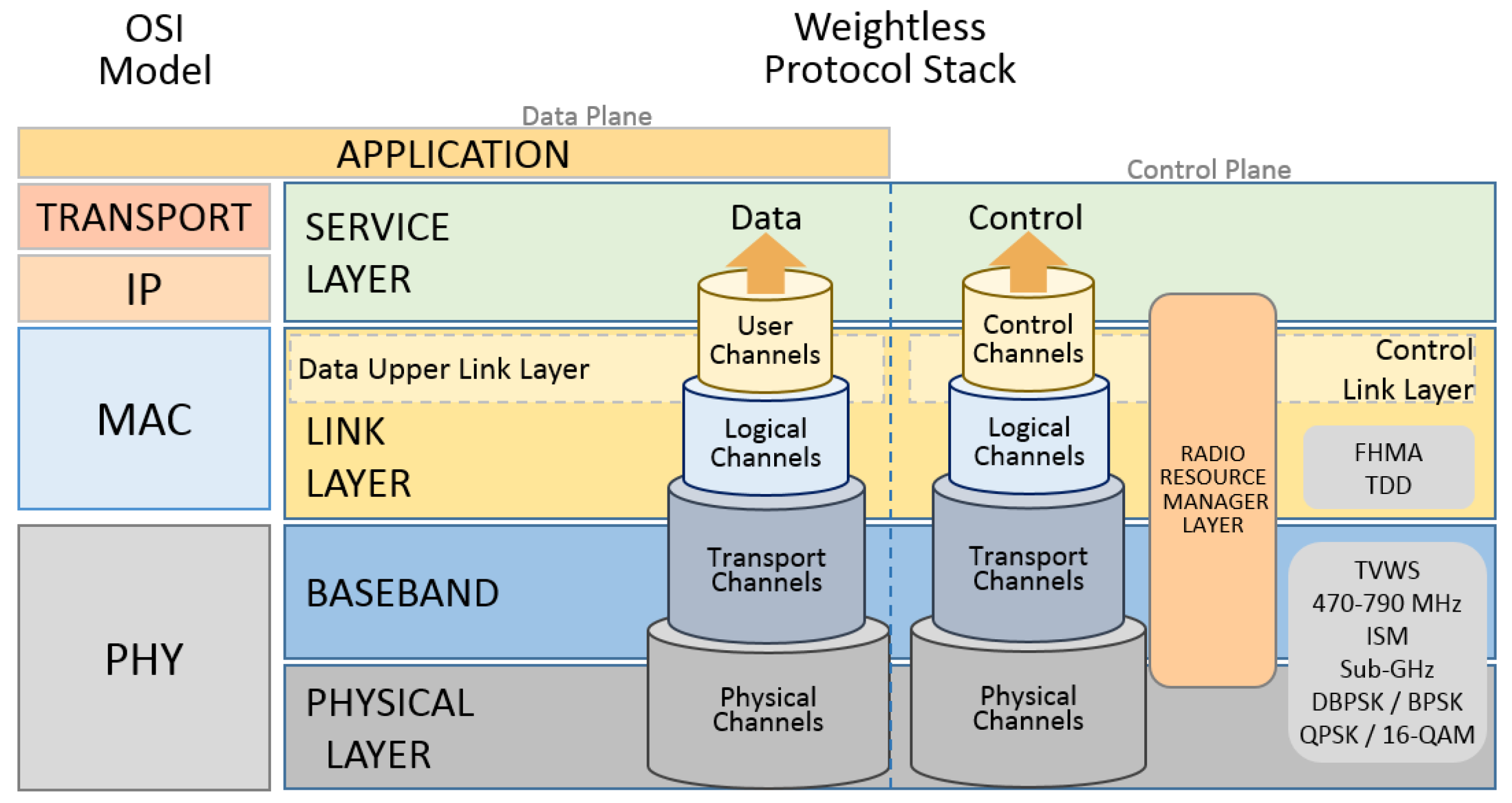
Like many other systems, Weightless uses channels to exchange data between the protocol layers. They are classified according to their role as control channels, logical channels transport channels, and physical channels. To allow base-band data exchange, the Physical layer (PHY) has three physical channels. They are named the downlink channel, uplink channel and uplink contended access channel. To transmit data from the base station to one or multiple EDs, the downlink channel is used. To uplink communication, from an ED to the access point, the uplink channel is used. The uplink contended access physical channel is also used to transmit data from the end devices to the base station. This channel is contended by the end devices and several EDs are allowed to transmit at the same time using this channel.
A Base-Band (BB) sublayer is responsible for providing the transport channels to transport the data to or from the Link Layer (LL). This is done by connecting the transport channels to the physical channels of PHY. Among the operations carried out by BB are identification of structured allocations within a frame structure and the transmission of the frames in both uplink and downlink directions, using appropriate physical channels. The Contended Access (CA) procedure is also controlled by BB using the uplink contended access physical channel. The communication between LL and BB is done by a set of transport channels and its channels are defined according to the type of information of addressing that is used. Connecting logical channels to the BB transport channels is the LL. LL is also responsible for retransmission control, reliability of the logical channels and for data fragmentation and reassembly. These processes can be either acknowledged or not. The multiplexing and de-multiplexing processes of the transport channels into logical control or user data channels is done by the LL. Thus, the LL provides such logical channels to allow the data or control traffic between the end devices and the BS or a BSN through an acknowledged and reliable or an unacknowledged and unreliable packet stream.
Radio Resource Manager (RRM) is present to control the traffic between an ED and its BS through Control Channels, using appropriate security provided by LL. The messages that control and maintain the connection between the ED and BS during the communication between them, is handled by RRM through the control channels. RRM also provides a downlink-only control message stream sent by the BSN, in order to maintain the link between the ED and BS. A Weightless protocol stack drawing can be seen in Figure 14.
Payload data is conducted from an ED and its BS through user channels that provide specific channels for unicast data, multicast data, interrupt data, and acknowledgement data. While the unicast user data channel is a bidirectional channel between the ED and the BS, the multicast data channel is a downlink-only channel. The multicast user data channel is an uplink-only channel. Weightless-W is a bidirectional communication technology that works on a Television White Space (TVWS) spectrum of 470–790 MHz. Its multiple access mechanism uses frequency hopping (Frequency Hopping Multiple Access—FHMA) with Time Division Duplexing (TDD). This can separate and coordinate the uplink and downlink transmission intervals. The data rates range from 1 Kbps to 10 Mb/s and the battery life is from three up to five years depending on usage. This technology supports star topology and 128-bit AES encryption in its packets. The packets can carry up to 10 bytes of payload, but encryption can be implemented end-to-end depending on other mechanisms, such as the network core. The error correction system is based on a Forward Error Control (FEC) algorithm not specified by the manufacturer. Channeling is done with 16 to 24 channels of 5 MHz bandwidth, depending on the frequency of use. The modulation of the channels is adaptive and can reach high rates at short distances according to the need of the application. The modulation can start with the Differential Phase Shift Keying (DBPSK) and BPSK for greater distances. Lower rates from 1 Kbps use Quadrature Phase Shift Keying (QPSK) or 16-QAM, reaching peaks of 10 Mbps over short distances [68,69,70,71].
Weightless-N is based on the Weightless-W standard and adapted for smaller distances and lower energy consumption (batteries last up to 10 years), sacrificing the transmission rate from 30 up to 100 Kbps. Weightless-N does not reach the data rate peaks that the Weightless-W can reach. Unlike Weightless-W, the Weightless-N is based on an Ultra Narrow Band (UNB) system and operates on the UHF frequency in the 800–900 MHz ISM band, providing only uplink communication. This system supports star topology and applies the UNB DBPSK (Differential Phase Shift Keying) modulation to ultra-narrow 200 Hz wide-band channels. With this simpler modulation, DBPSK, the device can save energy by making the battery last for up to 10 years [68].
Unlike W and N, the Weightless-P standard does not require a Temperature Compensated Crystal Oscillator (TCXO), which makes the system cheaper and less vulnerable to loss of synchronism due to the ambient temperature variation. This characteristic is only possible because it uses Gaussian Minimum Shift Keying (GMSK) modulation and an offset-QPSK modulation.
Weightless-P technology capacity was measured in a comparative way with the capacity of several multiple access technologies. The transmission power is set up serving a defined population of devices. The maximum flow for each multiple access mechanism allows 1404 bps for UNB, 93 bps for spread spectrum, and 4923 for NB (Narrow Band) [68].
2.9. IEEE 802.11 a/b/g/n/ah
Certainly, one of the most discussed and exploited standards in its functionalities and applications is IEEE 802.11. Its design has as an impulse the demand for high data transfer rates. Standardized by the IEEE as protocol for WLAN, its technology has evolved to meet the needs of increasingly specific demands. This evolution has initiated a group of IEEE 802.11 standards that have been merged, and named Wireless Fidelity (Wi-Fi). This group is the Wi-Fi Alliance [72] that certifies Wi-Fi products. In order to ensure that the Wi-Fi products meet the standards, this facility was named the WLAN System Toolbox which guarantees the compatibility of the market products in the PHY layer parameters. In addition, it contributes to the exploitation of the various different regional implementations, thus contributing to protocol evolution. The standard defines that communication devices are referred to as Stations (STAs) and can behave independently. Communication is directly between the two devices forming an ad hoc topology. The star topology happens when a certain STA is defined to be the traffic concentration point of other STAs, becoming an Access Point (AP). A STA-AP has a defined coverage area called the Basic Service Area (BSA) that allows it to associate with several STAs, forming a Basic Service Set (BSS). The STA-AP is usually connected to the internet or to a WAN network through a wired connection. It is also possible to have a Distributed System (DS) connecting the various STA-APs of the same LAN by forming a transport backbone infrastructure called the Extended Service Set (ESS) [73].
The IEEE 802.11 protocol stack follows the OSI reference model on its PHY and MAC layers. While the IEEE focuses on defining the PHY and MAC layers of the protocol as a grouped context, the Wi-Fi Alliance aims to work on the physical layer to facilitate peer-to-peer communications. The IEEE 802.11 standard has evolved since its first release in 1997. The PHY layer has evolved to work on the 2.4 GHz and 5 GHz ISM frequency bands with direct sequence spread spectrum (DSSS) and orthogonal frequency division multiplexing (OFDM). The channelization was segmented from 20 MHz for IEEE 802.11 up to 40 MHz for IEEE 802.11 n. The multiple transmission beam-forming technology improves the transmission and reception parameters and, consequently, transmission rates with greater values from 2 Mbps on IEEE 802.11 up to 600 Mbps for IEEE 802.11 n.
The MAC layer also had to adapt to this evolution. The MAC layer of IEEE 802.11 has as its main differential the mechanism of access to carrier sense multiple access with collision avoidance (CSMA/CA) as a medium access method. Features such as MAC level acknowledgments, fragmentation and reassembly, inter frame gaps and exponential back-off algorithm, roaming, synchronism, security and power saving mechanisms are adopted by IEEE 802.11. These techniques guarantee communication in a frequency band with a lot of spectral pollution. The 802.11a operates at the 5 Ghz band, with 52 orthogonal frequency-division multiplexing (OFDM) reaching less than 54 Mbps. Its transmission rate is fragmented on 48, 36, 24, 18, 12, 9 or 6 Mbps. As the 2.4 GHz band is more common and has more spectral pollution, the 5 GHz band offers an advantage over the IEEE 802.11a standard, due its spectrum low interference. Devices using IEEE 802.11a have a low transmission performance compared with IEEE 802.11b when dealing with obstacles. The IEEE 802.11b revision of the original standard was ratified in 1999 with a maximum transmission speed of 11 Mbps and uses the same CSMA/CA access method defined in the original standard. IEEE 802.11b standard uses the same 2.4 GHz, operating at a maximum theoretical speed of 54 Mbps.
With Machine to Machine (M2M) communications emerging, it was necessary to adjust the IEEE 802.11 standard that was primarily designed for computer communication. M2M communication demands distinct characteristics such as transmission range above 1 Km, transmission rates higher than 100 Kbps and low power consumption. There is also a need to have a network that supports a large number of nodes, operating under a policy of lower power consumption.
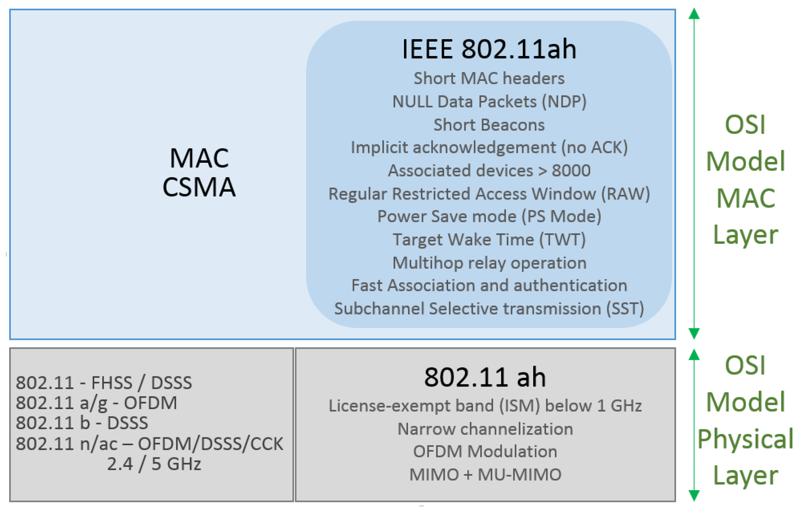
In an attempt to meet these requirements, the IEEE 802.11ah Task Group (TGah) [74] has guided the necessary improvements in the PHY and MAC layers of the IEEE 802.11 protocol to suit this scenario. The IEEE 802.11ah can be used not only as WSN but as well as back-haul infrastructure to connect the sensors to the data collectors. This is possible due to its large coverage and data rates capability. The IEEE 802.11ah amendment comes to solve some important limitations encountered to use Wi-Fi IEEE 802.11a/b/g/n when used to M2M communications. Its physical layer operates on ISM at 863-868.6 MHz in Europe, 950.8–957.6 MHz in Japan, 314–316 MHz, 430–432 MHz, 433.00–434.79 MHz in China, 917–923.5 MHz in Korea, and 902–928 MHz in USA. It uses an orthogonal frequency division multiplexing (OFDM) modulation scheme to achieve larger areas of coverage and increases the number of simultaneously operable stations. Frequency operations sub 1 GHz depend on local regulations for each region. For this reason, the bandwidth occupation is usually 1 MHz or 2 MHz, but, in some countries, broader configurations using 4, 8 and 16 MHz are also allowed. In the physical layer, the transmission is OFDM-based, working with 32 or 64 sub-carriers with 31.25 KHz spacing. The supported modulation techniques include BPSK, QPSK and 16 to 256 QAM with transmission/reception characteristics. These modulations are enhanced with beam forming by using a multi-input multi-output (MIMO) antenna scheme for single-users, and downlink multi-user MIMO [75]. However, the IEEE 802.11ah physical layer PHY BW channelization can be split into:
- Bandwidth of 1 MHz: Used to extended range of applications especially IoT or M2M applications that work with short burst low data rates. Range extension is obtained when using new Modulation and Coding Scheme index 10 (MCS 10) added to the previous 802.11 MCSs.
- Bandwidths of 2 MHz and more: This mode is oriented to data rates higher than those obtained with the 1 MHz bandwidth, using up to 16 MHz bandwidth with different Modulation and Coding Scheme (MCS) options. MIMO can be used to compose this solution to improve its performance [76].
The PHY layer of IEEE 802.11ah follows the evolution of the IEEE 802.11 standard for IEEE 802.11ac that uses Orthogonal Frequency Division Multiplexing (OFDM) modulation. Its Transmission System now has uplink MIMO antennas and downlink Multi-User MIMO (DL MU-MIMO) antennas. The previous 10, 20, 40, 80 and 160 MHz bandwidths were reduced to a 10 fold scale, resulting in channels with 1, 2, 4, 8, and 16 MHz bandwidths in the IEEE standard 802.11ah. At the same time, keeping the same number of carriers in each channel as previous versions, except for the 1 MHz channel as the guard band value between the sub-carriers cannot be reduced. In this way, the transmission of a symbol lasts 10 times longer than the previous standards. The increase in transmission range is a consequence of the combination of some other improvement factors in the PHY layer.
Due to its operation in the frequency range below 1 GHz, the transmission lost 8.5 dB of its link budget, in the LOS condition. Reducing 10 times the transmission channel bandwidth also reduces the noise level in the transmission. This increases the signal-to-noise ratio (SNR) by 10 dBs. With the adoption of a 1 MHz bandwidth channel, an increment of 3 dBs is achieved in the SNR, when compared to the 2 MHz bandwidth channel. Another 3 dBs of gain is improved on the SNR, with the 1 MHz channel supporting the repetition coding scheme for binary phase shift keying (BPSK) modulation, used with the 1/2 coding rate. The sum of the above gains brings us a total gain in the link budget of 24 dBs when compared to previous standards that operate at 2.4 GHz. When the concern is not the distance but the energy factor, the transmission power of the nodes can also be reduced using its low power mode operation. It reduces the power consumption, the cost of the device and, consequently, its size.
A disadvantage of using a narrower channel is a more sensitive transmission to flat fading that can be deep in indoor environments. This challenge is overcome by using the transmission selection of the best sub-channels for transmission at that time. This technique can increase up to 7 dBs [77] gain for systems working in indoor environments. In cases of node displacement during transmission, the Doppler effect occurs. It is necessary to estimate the channel and the correction of the transmission during transmission. To do this, IEEE 802.11ah changes the pilot carrier of each OFDM symbol [78]. The IEEE 802.11ah MAC layer incorporates the majority of the IEEE 802.11 main characteristics or has improved some of them. This is to optimize M2M communications, to support a large outdoor IoT network and to support energy-efficient communications for sensors [79].
Considering a scenario of a network densely populated by nodes, some factors that imply the containment and the characteristics of access to the medium were implemented, for example, the techniques of restricted access window adjustment, synchronization frame and hierarchical, and traffic indication map (TIM). They are implemented in the MAC layer to mitigate the problems of transmission collisions between hidden nodes [80]. The time window that a group of nodes belonging to the same AP has to access the medium and transmit is called the restricted access window (RAW). RAW is divided into slots that are individually assigned to some transmitting nodes of this group during each RAW. The same group of nodes dispute access to the medium through the same RAW assigned to them and, therefore, is a shared resource. Information such as the number of slots, the duration of each slot and the start time of each RAW is served by the RAW Parameter Set (RPS). The RAW technique prevents transmissions between hidden nodes from overlapping, by limiting the time that a station uses when competing for the transmission medium.
When a station needs to transmit, it must first detect and receive a complete and correct frame. Detection and identification of this frame causes the station to wait for the transmission window in order to avoid transmission collision. When attempting to access the medium, if the station does not receive a frame or is unable to identify the received frame, it must wait for a time interval called ProbeDelay to make another attempt to access the medium. The disadvantage of this procedure is to generate a medium access delay, which is reduced with the aid of the AP and its medium access control modes [81]. At the beginning of each RAW slot, the AP transmits a SYNC frame. The AP can detect the availability of the medium and initiate its transmission, after the end of the reception of the SYNC frame, not having to wait for the ProbeDelay timeout. Using the SYNC frame can reduce battery consumption by up to 30% [81].
Another improvement brought by IEEE 802.11ah is in regard to the power consumption and latency control. They are caused by the traffic indication map (TIM) based communication process, used in the downlink transmission demand detection mechanism. This method works detecting the demand of downlink communication through to TIM transmitted in the beacon by the AP. Thus, there is also a need for the node to respond to the AP with a PS-Poll frame. This procedure is eliminated by adopting a predefined schedule of the future wake-up time. With the data stored in the buffer, ready to be transmitted, the AP transmits the data to that node in its predefined window, thus saving energy that the node would expend by mapping the TIM, negotiating access to the medium, and receiving data from the AP.
One more characteristic that deserves to be highlighted is the use of PHY preamble fields is to indicate the continuity of the channel utilization. It is used to minimize collisions and to adopt the use of the bidirectional transient capacity (BDT). In addition, the adoption of the short inter frame space (SIFS) between uplink and downlink communications within the same transmission opportunity (TXOP) to improve medium access. These features also contribute to energy saving. Another improvement brought in favor of energy saving is scaling the value of the Max Idle Period field. This field defines the terminal sleep time. In this way, the terminal is able to go into a sleep mode for more than five years.
Reduction of processing, reduction of overhead in addition to reduction and optimization of access to the medium also drives the evolution of IEEE 802.11 PHY and MAC layers. In the PHY layer, the transmission recognition system that uses the acknowledgment (ACK) package has been optimized by reducing the ACK packet itself to the minimum necessary and also by creating the null data packet (NDP) carrying MAC. To keep the QoS parameters, the use of a new frame format dedicated to QoS called the Short QoS Data Frame. Its header was reduced to 12 bytes compared to the 30 bytes of the QoS data frame of IEEE 802.11n. In order to increase the number of stations up to a maximum of 8191, four encoding modes were defined in IEEE 802.11ah. They allow IEEE 802.11ah to compress the traffic indication virtual bitmap, used to signaling the association identifier of a station. A comparison of the IEEE 802.11 standards described is present in Figure 15.
Separating the stations in different types, with different procedures, common channel access time periods and other characteristics was added to the MAC protocol. These characteristics permits up to 8191 connected end devices already considering the collision issues among them. Although there is a need to maintain connection and synchronization with the APs, the IEEE 802.11ah terminals are equipped with mechanisms that provide energy saving during the period of inactivity. This ensures that the IEEE 802.11ah features long range and low power consumption when compared to other WLAN technologies, but remaining different from LP-WANs [82]. Using proper antennas and its features, the protocol can also be used in fixed point-to-point arrays typically in ranges of more than 1 km whenever there is line of sight (LOS). IEEE 802.11ah is also used for point-to-point communications or back-haul transport systems.
3. Long Range MAC Layer Protocols
Based on their own requirements such as rate, distance coverage, robustness, etc., the existing network protocols need some adaptation to meet the necessary requirements to attend IoT services. In some cases, some protocols were developed to meet IoT applications that demand far-reaching, reliable and robust transmission. Some of the protocols classified as protocols for LP-WANs are able to satisfy the demand for protocols with a large coverage area. LP-WANS protocols can overcome some mobile cellular network failures increasing strong adaptations to meet the IoT requirements.
LP-WAN are presented as good candidates to support several of the previously mentioned requirements of the IoT structure, and are able to surpass the short-range restriction of the LANs [11]. Among the possible solutions are the proprietary and unlicensed ISM band technologies Sigfox, LoRa/LoRaWAN, against mobile cellular network solutions such as LTE-A (Long Term Evolution—Advanced) and Narrow Band IoT (NB-IoT). Mobile cellular network technologies, with licensed spectrum or not, can satisfy energy and latency requirements, and it is better to use existing infrastructure [83,84,85].
Communication challenges and the broad set of specifications of M2M communication were added to LTE-based protocols. The development of MTC (Machine Type Communication) resources in the context of LTE (Long Term Evolution) were started in version 10, or Release 10 (R10), of the LTE-A standard [86]. During the development of M2M communication, the 3rd Generation Partnership Project (3GPP) committee defined a new profile, called CAT-0, or Category 0, for the operation of the MTC of low-power WAN (Wide Area Network) networks [87]. In release 13 (R13) from 2016, two special categories CAT-M for MTC and CAT-N for Narrowband-IoT (NB-IoT). These categories was included to support the characteristics of M2M communication and IoT technology, respectively [7]. Such categories will be better addressed in the document. In the literature, it is possible to find references to the CAT-N standard as NB-IoT and the CAT-M standard as LTE eMTC, LTE-M2M, LTE-M and CAT-M1. In this document, the notation LTE eMTC and NB-IoT will be used.
3.1. NB-IoT
According to the LTE eMTC regional specifications, it can operate only within the bandwidth of an LTE carrier. NB-IoT systems can be implemented as autonomous systems in the Global System for Mobile Communications (GSM) band, employed in the LTE bandwidth carrier or in the LTE bandwidth guard band. Due to the reduction of the NB-IoT bandwidth to 180 kHz, low data rate devices can have extended coverage, complexity reduction, and low power consumption. For scenarios with coverage problems of cellular network operators, NB-IoT is seen as the future of IoT devices using mobile network infrastructure [88].
With the pressure of the growing IoT connectivity, the 3rd Generation Partnership Project Agreement (3GPP) launched the project called CAT-N. This project presents a set of categories that offer different air interfaces specifically dedicated to low-power systems. These categories also include different characteristics of MIMO radiating system usage and different values of uplink and downlink data rates by exploiting the available GSM spectrum [89].
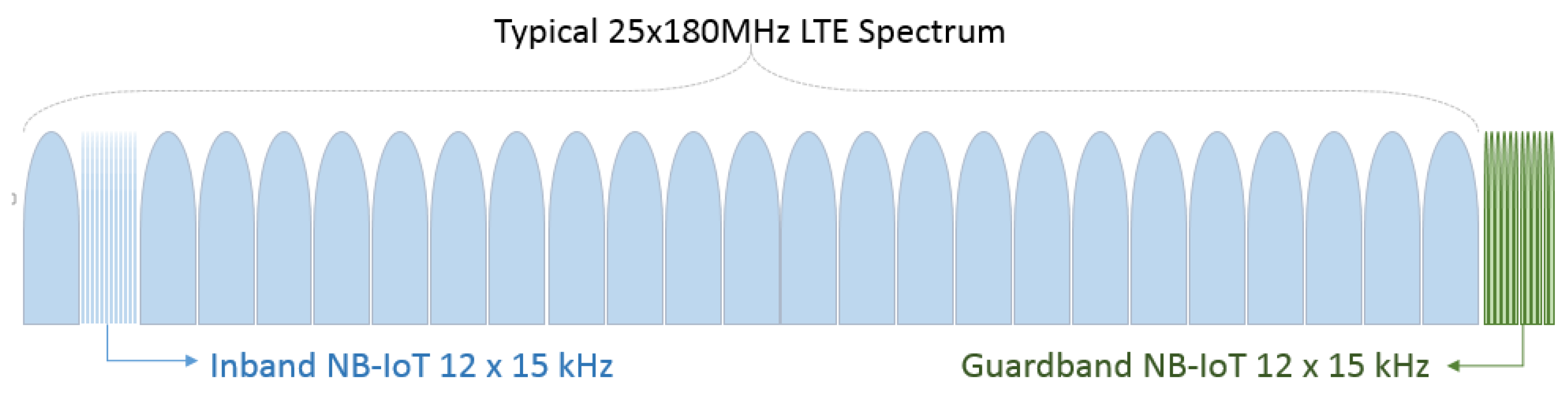
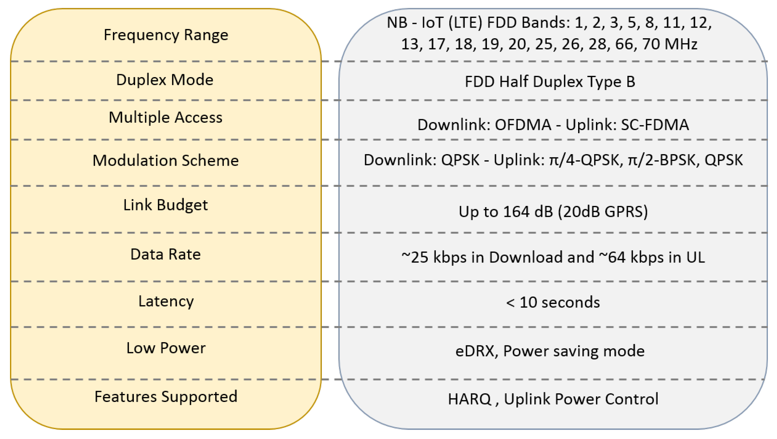
The NB-IoT covers all important components for communication in the M2M/IoT systems: low complexity, low power consumption, and long range. Some key features of the standard include a 180 kHz bandwidth and uplink and downlink transmission rates of about 250 Kbps with a half-duplex operation. However, even being a new radio interface, NB-IoT implementations can be made in the band of existing LTE carriers. In addition to this mode of operation, the NB-IoT also supports the guard band mode of operation of an LTE carrier. These two modes of operation are shown in Figure 16. It is important to differentiate NB-IoT from LTE eMTC, which refers to the use of LTE evolution for use of MTC and IoT [90].
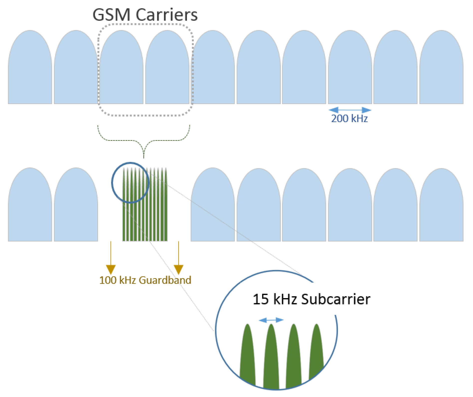
The third mode of operation of NB-IoT, which can be seen in Figure 17, is the deployment of NB-IoT using GSM carrier bands of the spectrum that has been assigned to legacy GSM cellular services [90].
In the downlink, NB-IoT uses Long Term Evolution Orthogonal Frequency Division Multiple Access (LTE/OFDMA) structures with spacing between sub-carriers of 15 kHz, while the uplink is able to use SC-FDMA with sub-carrier spacing at 3.75 kHz [91].
For the 3.75 kHz spacing between sub-carriers, the frame structure shows little differences from the structure defined for the LTE standard. Each LTE frame slot becomes 2 ms, the frame NB-IoT is then composed of five slots, totaling a period of 10 ms. The NB-IoT technology features a maximum coupling loss extended to 20 dB over the 140 dB LTE. It is achieved through an increase in the number of time repetitions and (/2)-BPSK single sub-carrier transmission, providing a coverage radius for NB-IoT of about 15 km [90]. The NB-IoT contains the following physical signal and channel resources as shown in Figure 18:
- Narrowband Primary Synchronization Signal (NPSS),
- Narrowband Secondary Synchronization Signal (NSSS),
- Narrowband Physical Broadcast Channel (NPBCH),
- Narrowband Reference Signal (NRS),
- Narrowband Physical Downlink Control Channel (NPDCCH),
- Narrowband Physical Downlink Shared Channel (NPDSCH).
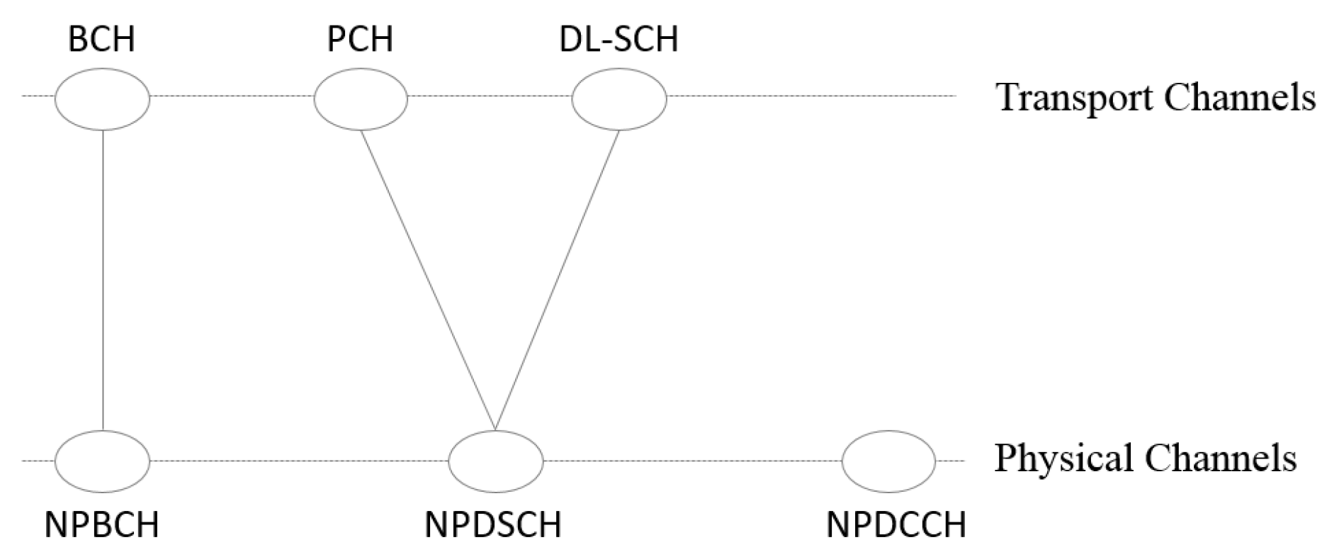
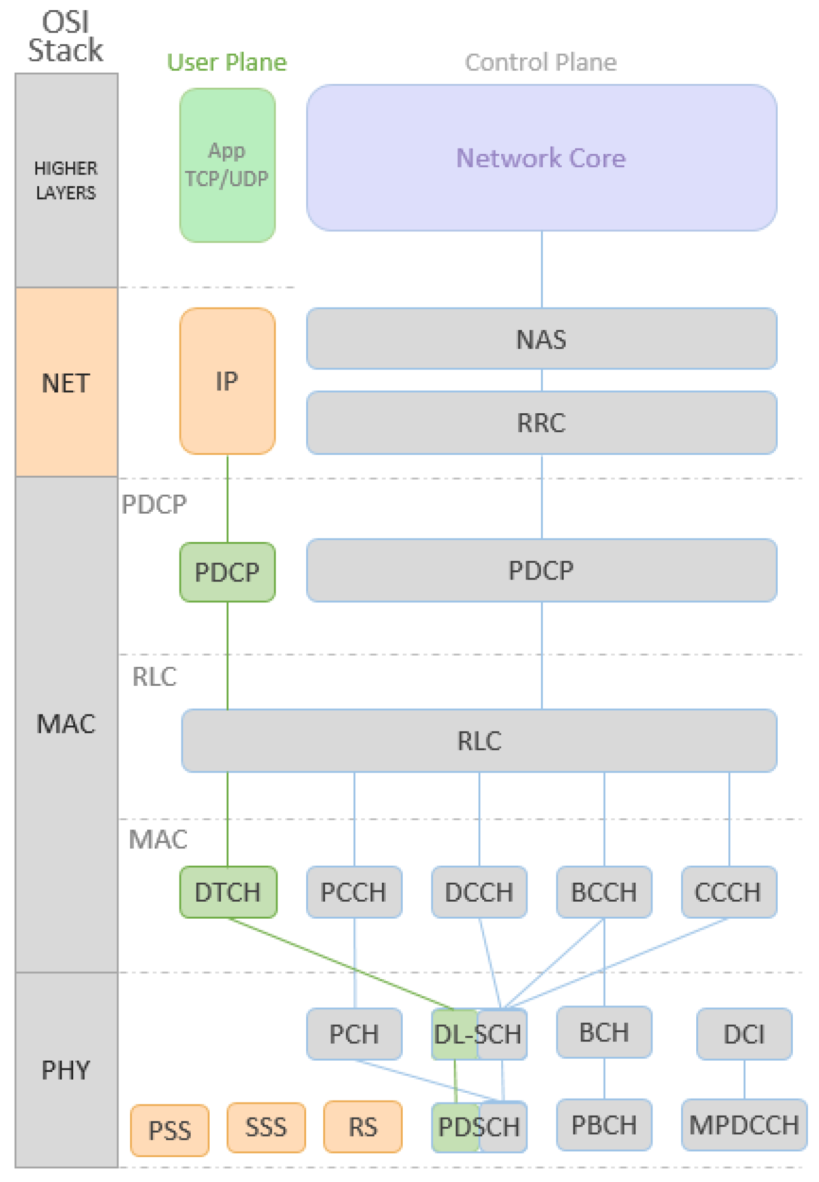
These channels and physical layer control signals in the NB-IoT are time multiplexed. Sub frames of the frame structure presented for the NB-IoT, are provided for different channels and physical signals. Each NB-IoT sub frame comprises a resource block in the frequency domain and 1ms in the time domain. The NPSS and NSSS signals are used to perform time and frequency synchronization as well as cell detection. An NRS signal is used to provide phase reference in the demodulation of downlink channels. The NB-IoT supports up to two NRS ports [92]. The NPBCH channel, transmitted in each sub frame 0 of the frame, loads the main information block, called the Master Information Block (MIB). The NPDCCH carries scheduling information for downlink and uplink data channels, in addition to the HARQ (Hybrid Automatic Repeat Request) confirmation information for the uplink data channel [93]. The NPDSCH channel carries higher layer data as well as paging message, system information and random access response message.
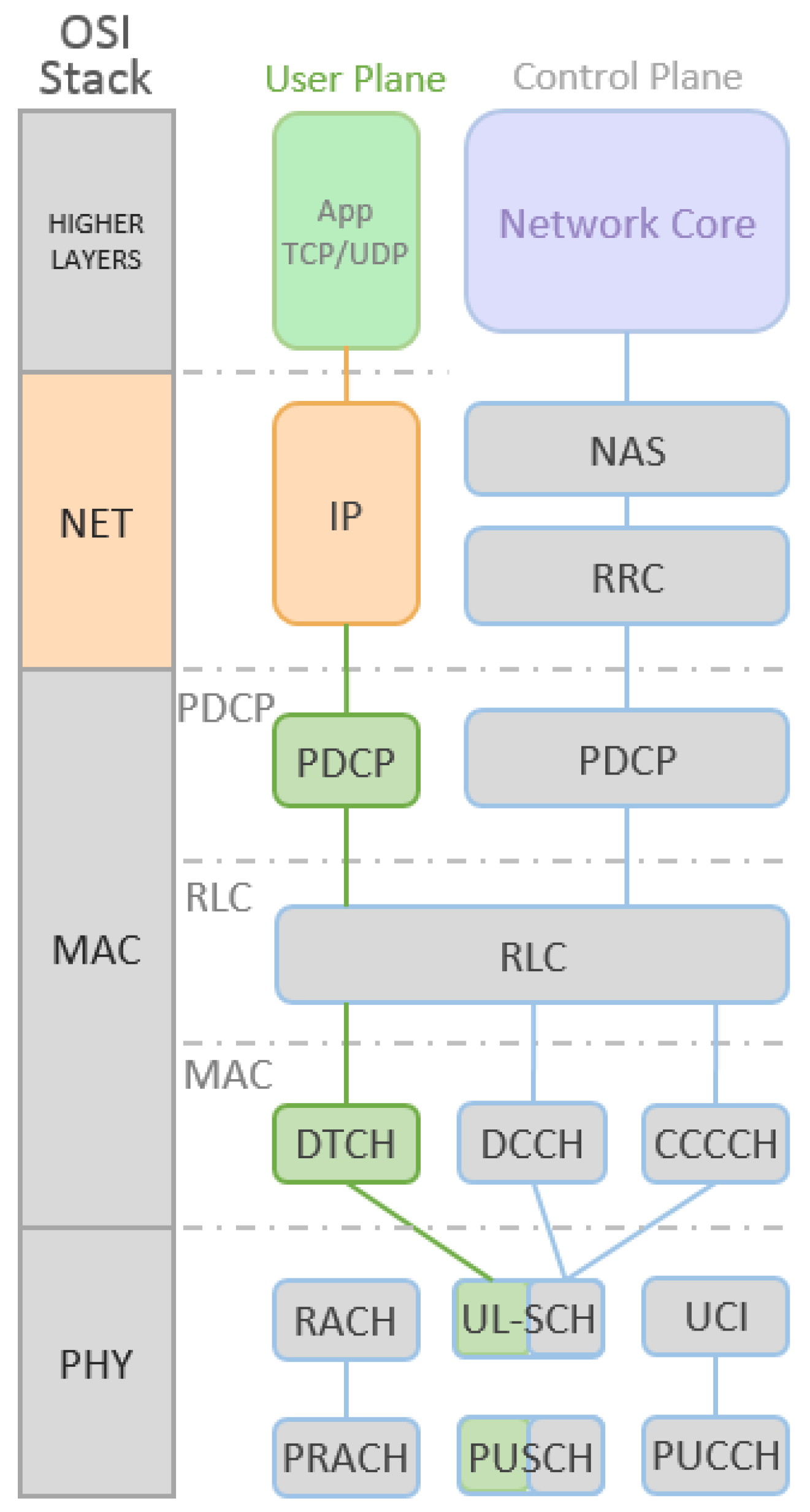
In uplink, the NB-IoT includes two physical channels that are described as (i) Narrowband Physical Random Access Channel (NPRACH) and (ii) Narrowband Physical Uplink Shared Channel (NPUSCH). NPRACH is a newly designed random access channel substituting the legacy LACH random access channel and uses a bandwidth of 1.08 MHz. It is more than the uplink bandwidth for the NB-IoT. The NPUSCH channel has two formats. The first is used to load uplink data and has a maximum block size of 1000 bits [94], which is much smaller than the LTE legacy. The second format is used to signal Hybrid Automatic Repeat reQuest (HARQ) recognition for the NPDSCH, and uses a repeat code for error correction.
NB-IoT reduces extreme simplicity for delay-tolerant applications such as meters, devices and sensors, providing wider coverage [95]. Common IoT solutions require low cost, high network device density and low data transfer. The NB-IoT technology aims, through LTE optimization, to meet this demand (more than 50 thousand devices) with low data rates in delay-tolerant applications. Figure 19 consolidate key parameters of NB-IoT.
3.2. LTE—Long Term Evolution
Long Term Evolution enhanced Machine-Type Communication (LTE eMTC) standards-based technologies support CAT-0 and CAT-M modes. While LPWAN LTE CAT-0 is commonly used to implement M2M/IoT, CAT-M reduces complexity keeping the coverage aspect using existing mobile cellular network infrastructure [96,97]. LTE eMTC counts on the same mobile technology benefits as security, privacy, data reliability and device identification [98].
With the applications involving the communication information generated by the human-to-human (H2H) services, the transmission data rate in the cellular networks increased considerably in the last decade. However, the traffic generated by M2M communication has different characteristics from those generated by H2H services in actual mobile technologies. M2M devices send more traffic than receive traffic when compared to H2H devices. For example, (H2H) service traffic has specific concentration characteristics at certain times of the day, while M2M traffic may present a uniform characteristic. In applications, such as measuring, M2M traffic tends to be periodic and mobility is short when compared to (H2H) communication devices. Thus, service quality requirements between M2M and H2M may be very different [99,100].
3GPP offered the appropriateness of LTE to permit MAC connection and PHY links through LTE networks and to optimize the technologies and mechanisms related to radio access. It provides LTE networks updates do deal with MTC and IoT requirements as follows:
- CAT-0, version 12 (R12): Since Category 1 (CAT-1) has low transmission capacity, a new category has become necessary to support the new challenges of MTC and IoT. The Category 0, or CAT-0 of R12 have lower hardware complexity when compared to CAT-1 [101].
- CAT-M, version 13 (R13): With the objective of new complexity reduction techniques, CAT-M was proposed in R13 [8].
- CAT-N, version 13 (R13): As major IoT devices, or MTCs, typically deal with long distance coverage to transmit few data bytes, CAT-N has been incorporated into the LTE specifications to support the required functionality. The main objectives of CAT-N is to improve distance coverage reducing its complexity and, as a consequence, a greater battery life cycle [89].
In order to fulfill the prerequisites necessary for LTE networks to be able to attend MTC services, 3GPP worked on the R12 to minimize power consumption and cost with new data traffic profile, hardware simplification and spectrum adjustments. LTE OFDMA modulation and SC-FDMA coding is maintained. 3GPP LTE Release 13 is being studied for IoT applications due to the fact that it uses a lower transmission bandwidth than the LTE terminals of previous releases. Release 13 works with freedom of spectrum occupancy within the LTE carrier using only 1.4 MHz of the 20 MHz available LTE carriers. A 15 dB link budget enhancement can guarantee longer distance coverage and better obstacle penetration factor [8,89,102,103,104]. LTE eMTC technology presents the same layers observed in the LTE protocol stack, shown in Figure 20. Briefly, the layers can be described as follows [90]:
- Non-Access Stratum (NAS): Works between Device and Network Core and is used for control, authentication and mobility management purposes.
- Radio Resource Control (RRC): In an eNodeB base station, this layer takes handover decisions, sends broadcast messages containing system information and controls the measurements of the device (UE) parameters.
- Packet Data Control Protocol (PDCP): Responsible for the compression and decompression of the user IP packet headers. It also performs data encryption, both on the user data plane and on the control plane data plane.
- Radio Link Control (RLC): Used to format and transport data between the Device and eNodeB base station, transfer upper layer Protocol Data Units (PDUs), error correction, concatenation, segmentation, and reassembly of Service Data Unit (SDUs).
- MAC: It performs physical transport channel mapping.
- Physical Layer: This layer carries all the information from the transport channels through the air interface.
With LTE-RACH fixed on the 1.08 MHz bandwidth, it is convenient to use LTE-eMTC channelization in multiples of its value, allowing compatibility with previous versions. The sub-frame structure of the LTE eMTC is the same as the LTE standard. From a frequency plane perspective, the 180 kHz bandwidth of a resource block is divided into 12 sub-carriers, each of them with 15 kHz bandwidth [105,106].
In terms of coverage, the LTE eMTC’s have a 155 dB link budget is achieved with the addition of 15 dB in channel prediction and resource tuning processes, enabling coverage of up to 11 km. These characteristics allow the LTE eMTC to have satisfactory communication even in conditions of excessive losses but transmission rates are affected [107]. In the downlink, the sub-frame structure of the LTE eMTC uses only a part of the LTE framework legacy. As LTE eMTC devices can be implemented with a narrow bandwidth, it is not possible to use the LTE control channels. Thus, it is necessary to create a MTC Physical Downlink Control Channel (MTC-PDSCH) and Physical Downlink Shared Channel (PDSCH) using LTE data channels. PDSCH transports higher data layers, segmented according to the transmission resources available.
The LTE eMTC devices depend on the NPSS and NSSS of the LTE standard for the acquisition of the carrier frequency of a cell and frame time usage. LTE signals can be used unchanged by LTE eMTC devices even under challenging coverage conditions. To improve reception performance, LTE eMTC devices can accumulate data received in buffer. This happens because the NPSS and NSSS signals are transmitted periodically. In order to discover the communication channel characteristics, the NRS signal is used to give estimates of channel behavior. This signal, which has a known pattern, is transmitted by the base station and performs downlink quality measurements [92,108].
For uplink data transmission, there is only one Physical Uplink Control Channel (PUCCH) that carries information such as scheduling requests, channel quality information, and transmission confirmations. The channel used by the user equipment to transmit data in uplink is the Physical Uplink Shared Channel (PUSH). Some sub-carriers can be used to assign resources to the user and are not used by the PUCCH or Physical Random Access Channel (PRACH) signals. To initiate the connection between the terminal and the base station and estimate the arrival time of the uplink message, the PRACH channel is used [106]. Figure 21 illustrates the LTE eMTC uplink channels.
Power consumption on IoT devices consists of standby and active power consumption (Idle and Connected modes, respectively). The power consumption of standby mode depends on the design and technology used, and essentially should not differ between LTE MTC and NB-IoT (both technologies have a battery life of approximately 10 years). Active energy consumption differs between these two technologies. Operating on active power consumption for downlink transmission, LTE eMTC has substantially higher throughput (both bandwidth and higher order modulation) than NB-IoT. As a result, it is possible to obtain an estimated active energy consumption 50% lower than the NB-IoT [91].
3.3. LoRa—Long Range Protocol
LoRa defines a physical layer technology developed by Cycleo in 2010, a company that was acquired by Semtech from Camarillo, United States of America.The LoRa module manufacturer offers the user a programmed library that allows communication between LoRa nodes, providing a simple link protocol [109]. Libelium, a company based in Zaragoza, Spain provides the tools and libraries needed to operate with LoRa [110]. The LoRa protocol is an open standard defining physical layer to use direct sequence spread spectrum (DSSS) with multiple spreading factors that range from 7 to 12. This combination allows the establishment of a relationship between distance coverage and the desired data rate. This technique in sub-GHz ISM band enables robust communication with a low power consumption for long distances. By using Frequency Shift Key (FSK) modulation with the optional use of forward error correction (FEC), LoRa allows demodulation of the signal even when the signal level is below the noise level. LoRa also counts on use of a frequency modulated (FM) chirp, based on a spread spectrum modulation with a chirp spread spectrum (CSS) variation. Thus, LoRa modulates data in different channels and speeds them, with a forward integrated error correction (FEC). Thus, it is possible to increase the coverage range while maintaining the low energy consumption characteristics offered by the FSK modulation. The usage of coding gain significantly improves receiver sensitivity and uses the full bandwidth spectra to transmit a signal. Then, it is more robust to channel noise and independent from the frequency compensations caused by low cost crystals. LoRa techniques assure signal demodulation lower than −50 dB SNR against 8 to 10 dB necessary for FSK demodulation of signals in different ISM bands. The frequency band used in Europe is the ISM band of 863–870 MHz regulated by European Telecommunications Standards Institute (ETSI). It uses 8 arbitrarily chosen channels, according to the current UN-111 in Spanish BOE-A-2013-4845 [111], with a bandwidth of 0.3 MHz per channel. For the ISM 902-928 MHz FCC regulation, LoRa works with 2.16 MHz per each one of the 13 channels.
To address the low-cost, low-power and robustness issues, LoRa Modulation counts on some key properties. Easy scalability of the LoRa modulation involves frequency and bandwidth domains, thus allowing its use in wide band direct sequence and narrow-band frequency hopping systems. This adaption can be done by programming the device to work according to its needs. The low-cost and low-power high efficiency can be achieved with a constant modulation scheme and the great link budget obtained using the processing gain, thus reducing the transmitted power. The asynchronous nature and high bandwidth used makes the LoRa signal more resistant to interference mechanisms, whether they are in-band or out-of-band inferences.
LoRa modulation presents better immunity, mainly to pulsed AM (Amplitude Modulated) interference, compared with FSK modulation systems. This is due to the period duration of the LoRa modulation is longer than the short duration typical bursts of FHSS systems. The effects of fading and multipath, common in urban and suburban areas, are faced with wide spreading of the chirps in the spectrum. The usage of Chirp Spread Spectrum (CSS) modulation, allows the system to be more resistant to these effects. The Doppler effect, when present, influences the quality of demodulated signals in applications. However, the CSS modulation shows small sensitivity to the Doppler effect due to the low frequency variation generated by it. This characteristic can be suitable for applications where the monitored targets have mobility support. With robustness against spectrum interference and unaware of fading and multipath effects, LoRa exceeds the link budget of conventional FSK systems and can increase up to four times the range, when compared to FSK systems. This is considering fixed transmission power and throughput. Like in reception, the transmission counts on the LoRa modulation characteristic to transmit or receive multiple signals, along the same channel. This is due to the advantage of the orthogonal spreading factor, with a low level of degradation. Localization services or other real-time applications such as ranging are easily handled by LoRa Modulation due to the capacity to discriminate linearly errors due to frequency or time shift effects [112].
The applications can make use of many possible data rates, payload sizes, and bandwidths according to its needs. Another level of diversity is obtained with the use of 125 kHz or 250 kHz according to the spreading factor used. The spectral scattering factor used influences both the final range obtained and the final acquired data rate. The higher the spectral scattering, the greater the maximum range obtained. In contrast, the data rate obtained will be lower. One base station can handle more than 700 end devices (EDs) depending on the conditions. To satisfy the network responsiveness capability, LoRa scheduling methods, and the frequency hopping method used have to assume that the RF channel conditions will not vary during a certain period of time. LoRaWAN is a network specification proposed by the LoRa Alliance that offers a MAC layer based on the LoRa modulation PHY layer. In order to meet the optimization characteristics of the data transmission rate, transmission resource utilization and energy usage, LoRaWAN MAC technology controls the transmission resources. These resources are the bandwidth to be occupied, the spread spectrum factor to be used, and which the transmission power of each node. This combination of features results in the Adaptive Data Rate (ADR) feature [113,114]. The three classes of devices specified are the following:
- Class A: The node can initiate the communication and only transmits to the gateway when necessary. To receive messages from the gateway, the node opens a receive window after each transmission.
- Class B: Beacons are used to synchronize nodes with the gateway through the insertions of received windows after its transmission.
The communication distance and the message transmission duration time define the data transmission rate reached. Thus, different rates of data transmission are due to the spreading the nodes transmission through different channels. ISM 868 MHz and 915 MHz bands typically operate with 125, 250, and 500 bandwidths (BW). The final data rate is obtained according to the SF and BW chosen. For BW = 7.8 kHz and SF = 12 it is possible to transmit at 22 bps and for BW = 500 kHz and SF = 7, it is possible to transmit up to 27 Kbps. Frequency hopping is also combined to improve external interference mitigation [68]. Figure 22 presents a representation of LoRa and LoRaWAN protocol stacks.
The LoRaWAN scalability is a major advantage since it can reach up to millions of devices depending on some factors. Among these factors are: the scenario, the average message transaction rate, the average size of the transmitted message, the number of LoRa channels used, and the number of GFSK channels used [114].
3.4. SigFox
SigFox is a technology that brings a new network and information strategy to IoT. Named by its developer, a group from Labège, France with the same name, SigFox is an IoT player with a network operator business model. Used by applications that require low data rates, SigFox is also classified as a Low Throughput Network (LTN) protocol, as defined by ETSI ERM TG28. Based on an Ultra Narrow Band (UNB) technology, Sigfox uses a 100 Hz transmission band in ETSI and ARIB (Japanese regulatory body Association of Radio Industries and Businesses) regions and a 600 Hz transmission band in FCC (Americas and Oceania) regions. This characteristic allows a data rate of 100 bps and 600 bps at ETSI and FCC regions, respectively [118,119].
SigFox protocol stack is composed of three main layers: Frame, MAC and Physical layers. Figure 23 depicts the comparison between SigFox and the OSI reference model. Sigfox operates on the Sub-GHz ISM band carrier using 863–870 MHz in ETSI and ARIB (Europe and Japan) and 902–928 MHz in FCC (Americas and Oceania). The bit rate depends on the bandwidth of each region. In ETSI and ARIB, the bandwidth used for the transmission is 100 Hz so, in this case, the bit rate is 100 bps. In the FCC regions, the 600 Hz transmission bandwidth occupancy permits a 600 bps transmission data rate [115].
The regulations in the FCC, ETSI, and ARIB regions determine the permitted transmission power in each case. In the ETSI regions, the maximum power transmission is 14 dBm per device for a maximum of two seconds of emission time, and a total of 140 messages per day. Sigfox Base Transmission Station (BTS) can transmit up to 26 dBm at a maximum. The regulations in the FCC region (Latin and Americas, United States of America and Asia) defines that each device can transmit up to 22 dBm with a maximum time transmission of 0.346 seconds, and a total of 140 messages per day. The FCC regulated BTSs can transmit up to 30 dbm. To overcome challenges with interference from the transmission medium, as well as transmission collisions that are inherent in the process, diversity comes as an efficient tool. Since there is no need to synchronize the network elements, devices can use an initial random frequency for transmission and then send two replicas randomly at different frequencies and at random time-slots. This simultaneous time and frequency diversity mechanism increases the robustness against interferences while increasing reception efficiency.
Different from mobile cellular systems, a Sigfox terminal is not attached to a single base station. With proper deployment, the message sent by a Sigfox terminal can be received by several base stations. This feature is called spatial diversity that, coupled with the time and frequency diversity of repetitions, are strong points in Sigfox protocol conception technology.
SigFox systems use D-BPSK (Differential Binary Phase Shift Keying) modulation to uplink and GFSK (Gaussian frequency shift keying) modulation to downlink. D-BPSK transmits at 1 bps using only 1 Hz of the operational band, which means that one single signal uses only a small part of the operational band, and therefoe brings higher efficiency in the spectrum medium access. Applications that demand low transmission data rates, with lower cost devices, high availability, and easy implementation coupled with the advantages of high link-budget, drive the use of D-BPSK modulation. Its physical layer employs a proprietary frequency hopping and frame repetition pattern to avoid interference of signals and it is responsible to determine how SigFox signals will be transmitted. The physical layer handles the modulation used, the bit rate and transmission power control, as well as the radio resource occupation.
UNB technology is identified by using a legacy Aloha protocol-based medium access technique called Random Frequency and Time Division Multiple Access (RFTDMA). This medium access technique has no medium access collision control method, thus allowing the terminals to access the medium at any instant of time, at any frequency (within the operating band), without any prior perception of medium occupancy [113]. The RFTDMA technique favors the low power consumption because it does not use energy to sense the medium before transmitting. It does not use any type of synchronization package or beacon technique, which also favors the cost of the terminals due to no need for expensive oscillator circuits. Another feature is that in RFTDMA the transmission frequencies are chosen randomly but within a continuous interval. A disadvantage that can be cited is the probability of colliding terminal packets that are transmitted simultaneously.
The Medium Access Control layer header adds field for device identification and error detecting codes. Sigfox devices are not synchronized with the network and can transmit anytime because Sigfox removed medium access control from its conception. The purpose of the frame layer is to receive the payload coming from the application layer; then, do the segmentation and deliver the fragments to the MAC layer. The MAC layer can identify and order the generation of the radio frames with a sequence number included. As usual on UNB systems, each transmission occupies a simple 100 Hz or 200 Hz bandwidth of available spectrum permitting high capacity for the SigFox network. High resilience is obtained as the SigFox signal power is squeezed into a narrow bandwidth supporting better behavior regarding interference. The energy concentration of the SigFox signal enables base stations to demodulate it easily, even if more powerful and spread interference signals are received simultaneously [83].
Depending on global regions, the transmission power varies from 14 dBm (ETSI) up to 22 dBm (FCC). UNB brings long range features thanks to D-BPSK modulation plus the low bit rate transmission performed by SigFox. This results in a highly sensitive base station receiver. The sensitivity of the base station receiver changes depending on the transmission bit rates of the devices. Sensitivity operates around −142 dBm for 100 bps and −134 dBm for 600 bps transmission rates. Such sensitivity offers a very large link budget. The transmission range achieved is defined by the channel conditions, interference, and the received noise level. With a high coupled irradiating system, the device can transmit up to 16.15 dBm EIRP (Effective Isotropic Radiated Power) with a 5.15 dBi antenna gain at the base station. With this combination, the receiver sensitivity has a link budget from −142 dBm up to 163.3 dBm. For transmission at 600 bps, the base station receiver sensitivity is 8 dB lower due the high transmission rate. However, it is compensated with 24.15 dBm EIRP devices transmission power. The typical sensitivity of the device considered as a receiver is −126 dBm. Devices are free to transmit on any operational band carrier and the base stations are ready to receive from all carriers anytime, permitting devices to work with low frequency accuracy [120].
SigFox has tailored a lightweight protocol to handle small messages. When dealing with short message transmissions, conventional protocols are not suitable due the overhead imposed by their design. Sigfox works with 26-byte packets carrying 12-byte data payloads. This gives Sigfox high transmission efficiency when compared to its useful data transmitted, against 20 bytes of ethernet header to carry the same 12 bytes plus 52 complementing bits. The payload data that can be put in a SigFox message rages from zero bits to 12 bytes composing a maximum packet size of 26 bytes. With a light protocol frame size, each transmission has less data to send, less energy is used and so the battery life increases. The uplink modulation is D-BPSK, the bit rate can be 100 bps or 600 bps according to the regional rules and the transmission power can go up to 22 dBm EIRP at radio configuration zone number two (RCZ2).
The topology followed by Sigfox is simple. It follows a star topology approach around the world. Objects transmit their messages to a SigFox base station. Point to point links connect a Sigfox base station to its Internet database and so, after receiving and decoding the message, data are sent to its internet database. Finally, SigFox cloud backend pushes the messages to the customer servers and IT platforms through APIs (Application Programming Interface).
Downlink communication procedure is triggered by the network node and therefore cannot be transmitted to the device at any time. Devices open their reception widow after a transmission, in order to receive the downlink packets. When the device needs to receive a downlink message, a flag is set in the uplink message requesting the sending of a downlink message. Only after this flag is sent will the device be ready to receive its downlink message during the interval of a time window that is set for receiving downlink messages. This procedure characterizes the sending of a downlink message to a specific device. To receive the broadcast messages, the nodes have a default time window for waiting to receive broadcast messages. This receiving window opens after the transmission of every uplink message. This procedure reduces the power consumption without communication requests, which exempts the use of network communication control. This makes the protocol simpler and allows greater network capacity. Without the need for traffic signaling and control in the MAC layer, the nodes are free to transmit at any time by simply going out of the sleep mode, transmitting and returning to the sleep mode. The transmission is then repeated two more consecutive times in random carriers in order to avoid collisions increasing capacity and scalability. Other aspects that contribute to the low power consumption are the fact that the message payload has only 12 bytes prolonging the life of the batteries of the element, reducing the cost of the nodes, and the low number of transmission per day. The modulation technique combined with a few hundred Hertz occupying its operational frequency band leads to high spectral efficiency. The small bandwidth used in the frequency spectrum available also contributes to the high capacity of the system. Due to its high reception sensitivity at the gateway and ability to transmit with a considerable level of power, Sigfox technology reaches a high link-budget. It is also possible to improve its performance adjusting its irradiating system [83,116].
4. Discussion and Open Issues
A comparison of the performance of the available MAC layer protocols is made here considering both groups, defined according to their range coverage (short and long range). Then, based on this discussion, open research issues are identified.
4.1. Short Range Protocols
This study demonstrated the diversity of patterns in the MAC layer of short range protocols, regarding their application characteristics. RFID and NFC technologies do not have many features in common although both were developed for short-range communications. For example, applications for identification and tracking uses RFID more commonly while NFC has been popularized among smartphones for exchanging media content and e-business devices for payment machines. There is a constant evolution of these technologies, adapting to new demands. Retaining miniaturization, energy consumption, and transmission efficiency characteristics.
Different features sometimes prevent a direct protocol comparison due to strong differences in the design and construction of their PHY and MAC layers. However, the PHY layer of the standard IEEE 802.15.4 is used as a base for many other short range protocols. In addition, protocols that present different solutions do not compensate the drawbacks of the IEEE 802.15.4, but rather they meet the requirements of the different applications. The comparison between BLE and IEEE 802.15.4 elucidates the lower power consumption of BLE against IEEE 802.15.4. Regarding throughput and energy efficiency, IEEE 802.11a indicates some advantages over IEEE 802.15.4. Using the PHY layer of IEEE 802.15.4 protocol, the Wireless-HART protocol implements different facilities in its MAC layer such as TDMA as the medium access technique and frequency hopping that increases its capacity [121,122].
The Z-Wave protocol presents the PHY and MAC layers with a different combination. Its MAC layer, standardized by ITU G.9959, presents the CSMA-CA inheritance middle access technique, security mechanisms, medium access optimization (such as backoff time, frame validation, and topology flexibility). These features allow high data rate performance with the range that the sub-GHz ISM band can provide.
Operating in the range of TVWS (470–790 MHz), the Weightless protocol needs to compensate the transmission bandwidth affected by spectral pollution. It does this by using complex modulation techniques such as Phase Shift Keying derivations and quadrature amplitude modulation options. Its transmission performance is also reinforced by the joint use of multiple access mechanisms such as the FHMA and TDD medium.
The different variations of the IEEE 802.11 protocol have been following the demands for wireless communications. The massive use of its variations that have evolved is a consequence of the demand for H2H services that require high transmission rates, with very dense networks. The IEEE 802.11ah variant has come to improve the performance and robustness of data communication. It is due to various mechanisms implemented in the MAC layer, such as Short MAC headers, short beacons, power saving mode, regular restricted access window, among others. In addition, it contributes to good transmission range performance, a reduction of channel usage compared to the previous IEEE 802.11 standards and new techniques for multiple antenna features.
The differences between applications and technical characteristics makes it difficult to compare short distance coverage protocols (Bluetooth, Bluetooth Low Energy, IEEE 802.11ah and IEEE 802.15.4) with long distance coverage protocols. Then, the next sub-section discusses the IoT long range protocols. Figure 24 presents a comparison of short range protocols studied in this survey.
4.2. Long Range Protocols
In the case of the LPWANs presented, the main parameters that differ are the distance range of the protocols discussed. Improvements, adaptations, and innovations have occurred mostly at the PHY layer while the MAC layer was adjusted as needed. Figure 25 presents a comparison of the long-range protocols studied in this survey.
With no power control and baud rate adjustment mechanisms, the LoRa modulation itself becomes inefficient for applications that demand frequent transmissions and high transmission rates (tens of kilobits or more). Due to these characteristics, LoRa is automatically surpassed by its evolution, the LoRaWAN. LoRaWAN improves the MAC layer with the power control mechanism by dividing the operational mode of the devices into classes and using adaptive data rates (ADR).
SigFox comes as a great choice for applications that do not require high data rates and require low power consumption. The transmission efficiency presented is due to the high robustness of the link, with a link budget greater than 150 dBm in some regions. This ensures robustness against interference, thanks to the narrow band occupied in the transmission. Its disadvantage is the low transmission rate as Sigfox takes a long time to transmit a message. This characteristic imposes hard operational conditions for a mobile supported application. In SigFox, LoRa, and LoRaWAN, the uplink capacity depends on spectrum occupation and quantity of messages transmitted simultaneously to uplink. These systems capacity is not limited by data traffic load. Figure 25 illustrates long range protocols characteristics.
Existing cellular network technologies are now heavily challenged by new IoT applications incoming their technological eco-system. Cellular networks are designed to operate with the human voice traffic profile that has a known and predictable pattern. With the advent of Internet traffic, mobile networks have had to adapt to meet an instant and floating demand for this service.
Based on the adaptations made from LTE network, NB-IoT networks are eminent solutions for harnessing the existing mobile cellular network infrastructure. NB-IoT emerges as a strong alternative given the available and well consolidated mobile network infrastructure. The adaptations made in LTE to support NB-IoTIoT services offer a new data traffic profile, different from the user services that demand for high transmission data rates. As data traffic from H2H applications such as audio, video, and voice tends to migrate to higher capacity systems such as 5G, NB-IoT capabilities become more widely available. This is an excellent alternative to the telecommunication operators since they have a 4G infrastructure and it is not compatible with the upcoming 5G. Then, telecommunication operators can re-use the available network infrastructure for IoT, based on NB-IoT, and perform its investments for 5G.
Challenged by IoT applications, it is not enough to adapt. Now, it is necessary to re-invent in order to support a new data traffic profile coming from objects which have completely different traffic, range, and time-based characteristics. Without the predefined parameter definitions regarding data transfer delay, NB-IoT has its limitations when used by systems that require some time dependency parameter. To meet this demand, LTE CAT-M technology, has brought to this new service profile an immediate deployed solution. Although they seem to be competitors, LTE CAT-M and NB-IoT protocols support services with different requirements for data transfer time requisites. They can become a complementary solution. Even though they are treated as networks for long distances, the differences between LP-WAN technologies and cellular mobile network technologies are very clear. The strong differences between the architectures of the PHY and MAC layers of these two types of networks make it difficult to have a fair comparison between them. Better comparison bases could be provided considering the same application (or solution), deployed using both technologies.
4.3. Open Issues
In this rapidly evolving scenario, the emergence of new features, interoperability and performance aspects to be studied or validated is constant. Considering the discussion presented here and the characteristics of the protocols, the following open research topics are identified:
- Regardless of the technology used in any solution or application, the information exposure always raises questions regarding each protocol security requirements, emphasizing that each solution requires different aspects of security. Beyond the scope of fixed or mobile WSNs security [123], from this study, the use of AES encryption by most protocols is clear. Some protocols that do not use it have some other methods to ensure data privacy at the MAC layer level such as proprietary coding or the vendor specific modulation type. Proprietary technologies like Sigfox and Wireless-Hart ensure this security by keeping their development features closed, limiting access to their techniques. Based on the information presented, it is clear that, in terms of security, there is a need to treat data at upper layers and have security embedded in the solution code, aspects that deserve more attention.
- The ability of terminals to roam between technologies is also an untreated topic. The design of hybrid systems such as multi-protocol gateways seems to be an unavoidable consequence of these protocol heterogeneities [124]. The rapid evolution of hardware solutions induces the development of multi-protocol platforms and systems [125], multi-band radio interfaces with adaptive and opportunistic techniques such as 5G. These protocols are required to be inter-operable in different layers, allowing performance comparisons. For example, in areas of roaming between different protocol technologies, systems and network operators, technical alliances necessary to obtain a good cross-border roaming, including the security aspect.
- With the current evolution, devices need several connectivity technologies. The same application can use more than one connectivity technology and terminal roaming between technologies can happen abruptly. Once the technology roaming aspect has become part of the scenario, the need for a verification of existing tools or solutions will arise to bring the interconnectivity standardization to the MAC layer. Thus, leaving the application layer and its applications, operating transparently and inherently to the protocol technology being used.
- Since there are such heterogeneity, connectivity, and interconnection, there are coexistence, dispute for resources, and interference. Although numerous works have been done on the performance of these protocols, little has been published on practical comparisons in identical scenarios. This comparison can point out the capabilities offered by each protocol and investigate their characteristics in a co-existent environment. As ISM bands are preferred by LP-WAN protocols, their coexistence in the same scenario calls for more studies so that more can be learned about the inter-technology interferences that can degrade their qualities.
- For more critical environments and applications, such as healthcare and some industrial environments, reliability may be more important than other features. Highly reliable services may sacrifice other characteristics such as latency. Studies of data "acknowledgment" mechanisms demand flexibility in the packet sizes used and network responsiveness to these characteristics.
- Some techniques or applications, primarily for management platform purposes, are still dependent on broadcast and multicast functions inherited from IP networks that still need to be adapted or evolved. Broadcast, multicast, and control channels are also emerging aspects that are having their applications questioned without many specific studies.
5. Lessons Learned
Diversity of application scenarios and network deployments directly or indirectly interfere in each protocol performance. Protocol performance can be affected by uplink message factors, downlink message factors, throughput capability, delay tolerance, payload size, power consumption, or even the number of elements supported by the network [126]. Current and new applications come to explore and provide inputs for new studies and evaluations regarding transmission parameters, timing requirements, co-interference, and multi-use platform parameters. Concepts are being disrupted in order to follow the user needs evolution.
Coexistence of systems in the same frequency band deserves attention and detailed studies due to the explosive growth of technologies that will coexist in the same spectrum. A strong example is the coexistence of Sigfox, and LoRa protocols that already demand coexistence studies. Some adjustments, which are being done to adapt the current technologies with the new ones, at the same time that it attends the evolutional demand, are generating competition for resources.
M2M communication networks are being used on mobile devices as payment systems. In some cases, there is a sacrifice of energy to obtain a better result in another aspect such as latency, delivery time, or transmission data rates. There is little flexibility for protocols to adapt to these scenarios. Often, the absence of control mechanisms can be justified regarding the energy aspect. Since these are new technologies in new scenarios for new applications, many parameters and capacities are informed by studies and theoretical comparisons [127]. Deployment and operation of these new technologies can present results far beyond those proposed by technology.
6. Conclusions
The study performed in this work explores the diverse characteristics of most of the MAC layer protocols used that have been adapted, evolved or created to meet the increasing needs and demands of new emerging IoT applications. The aspects addressed here are mainly related to physical and MAC layers bringing a comparative panorama to the range coverage, data rates, robustness and energy efficiency aspects.
The discussion illustrates the different operating and performance characteristics of each protocol for different applications, within the same scenario, based on different MAC layer technologies. The lack of interoperability between protocols that challenges their heterogeneity in several aspects leads the paradigm of homogeneity to its rupture. Characteristics of robustness, distance coverage, data transmission rates, and energy efficiency are aspects that contribute to protocol diversity allowing them to serve diverse applications.
Finally, the MAC layer characteristics necessary to be considered in the development of hybrid or heterogeneous platforms were presented. This interoperability can always be obtained at the application level; however, the interoperability of lower-layers can increase the performance of hybrid or heterogeneous devices, mainly in terms of energy consumption.
Author Contributions
L.O. collected and performed a deep analysis and reviewed the related literature on the topic, wrote the first draft of the document, performed the comparison study and identified some open research issues. J.J.P.C.R. supervised all the study, consolidated the comparison analysis and open issues, reviewed the structure and the first draft. All the other authors reviewed the text carefully, verified the comparison study, and reviewed the identified open issues. All the authors contributed equally to the scope definition, motivation, and focus of the paper.
Funding
This study was financed by National Funding from the FCT—Fundação para a Ciência e a Tecnologia through the UID/EEA/50008/2013 Project; by the Government of the Russian Federation, Grant 08-08; by Finep, with resources from Funttel, Grant No. 01.14.0231.00, under the Centro de Referência em Radiocomunicações–CRR project of the Instituto Nacional de Telecomunicações (Inatel), Brazil; by Brazilian National Council for Research and Development (CNPq) via Grant No. 309335/2017-5; and by the Coordenação de Aperfeiçoamento de Pessoal de Nível Superior - Brasil (CAPES) - Finance Code 001.
Conflicts of Interest
The authors declare no conflict of interest.
References
- IEEE GET Program. IEEE 802 GET 802(R) Standards. Available online: https://ieeexplore.ieee.org/browse/standards/get-program/page/series?id=68 (accessed on 10 December 2018).
- Buratti, C.; Conti, A.; Dardari, D.; Verdone, R. An overview on wireless sensor networks technology and evolution. Sensors 2009, 9, 6869–6896. [Google Scholar] [CrossRef] [PubMed]
- IEEE Computer Society. IEEE Standards IEEE 802.15.4-Part 15.4—Wireless MAC and PHY Specifications for Low-Rate Wireless Personal Area Networks—LR-WPANs, 2003th ed.; The Institute of Electrical and Electronics Engineers, Inc.: Piscataway, NJ, USA, 2003. [Google Scholar]
- IEEE 802.15.6-2012. IEEE Standard for Local and Metropolitan Area Networks—Part 15.6: Wireless Body Area Networks; IEEE Standard for Information Technology; IEEE: Piscataway, NJ, USA, 2012; Volume 802, pp. 1–271. [Google Scholar]
- Alam, M.M.; Hamida, E.B. Surveying wearable human assistive technology for life and safety critical applications: Standards, challenges and opportunities. Sensors 2014, 14, 9153–9209. [Google Scholar] [CrossRef] [PubMed]
- Alam, M.M.; Hamida, E.B. Performance Evaluation of IEEE 802.15. 6 MAC for Wearable Body Sensor Networks Using a Space-Time Dependent Radio Link Model; IEEE: Piscataway, NJ, USA, 2014; pp. 441–448. [Google Scholar]
- Kwak, K.S.; Ullah, S.; Ullah, N. An overview of IEEE 802.15. 6 standard. In Proceedings of the 2010 3rd International Symposium on Applied Sciences in Biomedical and Communication Technologies (ISABEL), Roma, Italy, 7–10 November 2010; pp. 1–6. [Google Scholar]
- Flore, D.; 3GPP. Evolution of LTE in Release 13; 3GPP: Sophia Antipolis, France, 2015. [Google Scholar]
- Roy, S.; Jandhyala, V.; Smith, J.R.; Wetherall, D.J.; Otis, B.P.; Chakraborty, R.; Buettner, M.; Yeager, D.J.; Ko, Y.C.; Sample, A.P. RFID: From supply chains to sensor nets. Proc. IEEE 2010, 98, 1583–1592. [Google Scholar] [CrossRef]
- Finkenzeller, K. RFID Handbook, 3rd ed.; Wiley: Hoboken, NJ, USA, 2010. [Google Scholar]
- Atzori, L.; Iera, A.; Morabito, G. The internet of things: A survey. Comput. Netw. 2010, 54, 2787–2805. [Google Scholar] [CrossRef]
- International Organization for Standardization (ISO). ISO/IEC 14443-1:2016 Standard, Identification Cards—Contactless Integrated Circuit Cards—Proximity Cards—Part 1: Physical Characteristics. Available online: https://www.iso.org/standard/70170.html (accessed on 11 May 2018).
- Issovits, W.; Hutter, M. Weaknesses of the ISO/IEC 14443 protocol regarding relay attacks. In Proceedings of the IEEE International Conference on RFID-Technologies and Applications (RFID-TA), Sitges, Spain, 15–16 September 2011; pp. 335–342. [Google Scholar]
- International Organization for Standardization (ISO). ISO/IEC 14443-2:2016—Identification Cards—Contactless Integrated Circuit Cards—Proximity Cards—Part 2: Radio Frequency Power and Signal Interface. Available online: https://www.iso.org/standard/66288.html (accessed on 14 May 2018).
- Bhuptani, M.; Moradpour, S. RFID Field Guide: Deploying Radio Frequency Identification Systems; Prentice Hall PTR: Upper Saddle River, NJ, USA, 2005. [Google Scholar]
- GS1 Standards. EPC/RFID-Standards. Available online: https://www.gs1.org/standards/epc-rfid (accessed on 14 May 2018).
- GS1 Standards. EPCIS and Core Business Vocabulary (CBV)—Standards. Available online: https://www.gs1.org/standards/epcis (accessed on 14 May 2018).
- Coskun, V.; Ozdenizci, B.; Ok, K. A survey on near field communication (NFC) technology. Wirel. Pers. Commun. 2013, 71, 2259–2294. [Google Scholar] [CrossRef]
- International Organization for Standardization and International Electrotechnical Commission. ISO/IEC 18092:2013/Cor 1:2015. Available online: https://standards.iso.org/ittf/PubliclyAvailableStandards/index.html (accessed on 10 December 2018).
- Want, R. Near field communication. IEEE Pervasive Comput. 2011, 10, 4–7. [Google Scholar] [CrossRef]
- Kurzweil, R. The singularity is near. In Ethics and Emerging Technologies; Springer: Berlin, Germany, 2014; pp. 393–406. [Google Scholar]
- Atzori, L.; Iera, A.; Morabito, G. From “Smart Objects” to “Social Oobjects”: The Next Evolutionary Step of the Internet of Things. IEEE Commun. Mag. 2014, 52, 97–105. [Google Scholar] [CrossRef]
- Zhao, Y.; Mahoney, B.; Smith, J.R. Analysis of a Near Field Communication wireless power system. In Proceedings of the IEEE Wireless Power Transfer Conference (WPTC), Aveiro, Portugal, 5–6 May 2016; pp. 1–4. [Google Scholar]
- Coskun, V.; Ok, K.; Ozdenizci, B. Near Field Communication (NFC): From Theory to Practice; John Wiley & Sons: Hoboken, NJ, USA, 2011. [Google Scholar]
- NFC-Forum. The Near Field Communication—Specification Releases. Available online: https://nfc-forum.org/ (accessed on 24 July 2018).
- Madlmayr, G.; Langer, J.; Scharinger, J. Managing an NFC ecosystem. In Proceedings of the IEEE 7th International Conference on Mobile Business (ICMB’08), Barcelona, Spain, 7–8 July 2008; pp. 95–101. [Google Scholar]
- Bruno, R.; Conti, M.; Gregori, E. Bluetooth: Architecture, protocols and scheduling algorithms. Clust. Comput. 2002, 5, 117–131. [Google Scholar] [CrossRef]
- Bluetooth SIG. Bluetooth Specification Version 5.0 Vol 0: Master Table of Contents & Compliance Requirements; Bluetooth Special Interest Group (SIG) Specifications: Kirkland, WA, USA, 2016; Available online: https://www.bluetooth.com/specifications/adopted-specifications (accessed on 24 July 2018).
- Xiao, Y.; Pan, Y. Emerging Wireless LANs, Wireless PANs, and Wireless MANs: IEEE 802.11, IEEE 802.15, 802.16 Wireless Standard Family; John Wiley & Sons: Hoboken, NJ, USA, 2009; Volume 57. [Google Scholar]
- Website, B.T. Bluetooth Protocol Specifications. Available online: https://www.bluetooth.org/Technical/Specifications/adopted.htm (accessed on 31 May 2017).
- Afonso, J.A.; Maio, A.J.F.; Simoes, R. Performance Evaluation of Bluetooth Low Energy for High Data Rate Body Area Networks. Wirel. Pers. Commun. 2016, 90, 121–141. [Google Scholar] [CrossRef] [Green Version]
- Instruments, T. Application Note AN092—Measuring Bluetooth® Low Energy Power Consumption; Technical Report; Texas Instruments: Dallas, TX, USA, 2012. [Google Scholar]
- Ergen, S.C. ZigBee/IEEE 802.15.4 Summary; University of California: Berkeley, CA, USA, 2004; Volume 10, p. 17. Available online: http://users.eecs.northwestern.edu/~peters/references/ZigtbeeIEEE802.pdf (accessed on 31 May 2017).
- Baronti, P.; Pillai, P.; Chook, V.W.; Chessa, S.; Gotta, A.; Hu, Y.F. Wireless sensor networks: A survey on the state of the art and the 802.15. 4 and ZigBee standards. Comput. Commun. 2007, 30, 1655–1695. [Google Scholar] [CrossRef]
- Zheng, J.; Lee, M.J. A comprehensive performance study of IEEE 802.15.4. Sens. Netw. Oper. 2006, 4, 218–237. [Google Scholar]
- Sheng, Z.; Yang, S.; Yu, Y.; Vasilakos, A.; Mccann, J.; Leung, K. A survey on the ietf protocol suite for the internet of things: Standards, challenges, and opportunities. IEEE Wirel. Commun. 2013, 20, 91–98. [Google Scholar] [CrossRef]
- Shelby, Z.; Bormann, C. 6LoWPAN: The Wireless Embedded Internet; John Wiley & Sons: Hoboken, NJ, USA, 2011; Volume 43. [Google Scholar]
- Centenaro, M.; Vangelista, L.; Zanella, A.; Zorzi, M. Long-range communications in unlicensed bands: The rising stars in the IoT and smart city scenarios. IEEE Wirel. Commun. 2016, 23, 60–67. [Google Scholar] [CrossRef]
- Rao, S.M.; Krishna, M.V.; Reddy, V.M. Performance analysis of hybrid protocol for IEEE802.15.4 based wireless sensor network. Int. J. VLSI Embed. Syst. Signal Process. 2015, 2, 3–7. [Google Scholar]
- Fareeha Zafar, M. Performance Analysis of IEEE 802.15.4 in Terms of Energy Efficient Parameters within WSN. J. Appl. Environ. Biol. Sci. 2014, 4, 548–557. [Google Scholar]
- Mikhaylov, K.; Plevritakis, N.; Tervonen, J. Performance analysis and comparison of Bluetooth Low Energy with IEEE 802.15. 4 and SimpliciTI. J. Sens. Actuator Netw. 2013, 2, 589–613. [Google Scholar] [CrossRef]
- Yuan, W.; Wang, X.; Linnartz, J.P.M.G.; Niemegeers, I.G.M.M. Coexistence performance of IEEE 802.15. 4 wireless sensor networks under IEEE 802.11 b/g interference. Wirel. Pers. Commun. 2013, 68, 281–302. [Google Scholar] [CrossRef]
- Srivastava, R.; Kumar, A. Performance analysis of beacon-less IEEE 802.15. 4 multi-hop networks. In Proceedings of the Fourth International Conference on Communication Systems and Networks (COMSNETS), Bangalore, India, 3–7 January 2012; pp. 1–10. [Google Scholar]
- IEEE 802.15 WPAN™ Task Group-4e (TG4e). IEEE 802.15 WPAN Document Archive. Available online: http://grouper.ieee.org/groups/802/15/pub/Download.html (accessed on 12 June 2018).
- Guglielmo, D.D.; Brienza, S.; Anastasi, G. IEEE 802.15.4e: A survey. Comput. Commun. 2016, 88, 1–24. [Google Scholar] [CrossRef]
- De Guglielmo, D.; Anastasi, G.; Seghetti, A. From IEEE 802.15.4 to IEEE 802.15.4e: A step towards the internet of things. In Advances onto the Internet of Things; Springer: Cham, Switzerland, 2014; Volume 10, pp. 135–152. [Google Scholar]
- Oliveira, L.M.; Rodrigues, J.J. Wireless Sensor Networks: A Survey on Environmental Monitoring. JCM 2011, 6, 143–151. [Google Scholar] [CrossRef]
- Shin, Y.S.; Lee, K.W.; Ahn, J.S. Analytical performance evaluation of IEEE 802.15.4 with multiple transmission queues for providing QoS under non-saturated conditions. In Proceedings of the 16th Asia-Pacific Conference on Communications (APCC), Auckland, New Zealand, 31 October–3 November 2010; pp. 334–339. [Google Scholar]
- Al-Nidawi, Y.; Yahya, H.; Kemp, A.H. Impact of mobility on the IoT MAC infrastructure: IEEE 802.15.4e TSCH and LLDN platform. In Proceedings of the IEEE 2nd World Forum on Internet of Things (WF-IoT), Milan, Italy, 14–16 December 2015; pp. 478–483. [Google Scholar]
- Santhi, S.; Divya, B. Energy Consumption using IEEE802.15.4 Sensor Networks. Int. J. Comput. Appl. 2015, 116, 30–33. [Google Scholar]
- Petersen, S.; Carlsen, S. WirelessHART Versus ISA100.11a: The Format War Hits the Factory Floor. IEEE Ind. Electron. Mag. 2011, 5, 23–34. [Google Scholar] [CrossRef] [Green Version]
- International Society of Automation (ISA). ISA100, Wireless Systems for Automation—ISA. Available online: https://www.isa.org/isa100/ (accessed on 15 May 2017).
- FieldComm-Group. HART Communication Protocol. Available online: https://fieldcommgroup.org/ (accessed on 15 May 2017).
- WINA. Wireless Industrial Networking Alliance (WINA). Available online: http://www.wina.org/ (accessed on 15 May 2017).
- Zigbee-Alliance. Zigbee Specifications. Available online: http://www.zigbee.org/ (accessed on 15 May 2017).
- Nobre, M.; Silva, I.; Guedes, L.A. Routing and scheduling algorithms for WirelessHARTNetworks: A survey. Sensors 2015, 15, 9703–9740. [Google Scholar] [CrossRef] [PubMed]
- Iordache, V.; Gheorghiu, R.A.; Minea, M. Analysis of interferences in data transmission for wireless communications implemented in vehicular environments. In Proceedings of the Federated Conference on Computer Science and Information Systems (FedCSIS), Prague, Czech Republic, 3–6 September 2017; pp. 849–852. [Google Scholar]
- Song, J.; Chen, D.; Nixon, M.; Lucas, M.; Pratt, W.; Han, S.; Mok, A. WirelessHART: Applying Wireless Technology in Real-Time Industrial Process Control. In Proceedings of the IEEE Real-Time and Embedded Technology and Applications Symposium(RTAS), St. Louis, MO, USA, 22–24 April 2008; pp. 377–386. [Google Scholar]
- Yassein, M.B.; Mardini, W.; Khalil, A. Smart homes automation using Z-wave protocol. In Proceedings of the International Conference on Engineering MIS (ICEMIS), Agadir, Morocco, 22–24 September 2016; pp. 1–6. [Google Scholar]
- Z-Wave Alliance—Home Management. Available online: https://z-wavealliance.org/home-management/ (accessed on 9 May 2018).
- ITU T-REC-G.9959: Short Range Narrow-Band Digital Radiocommunication Transceivers—PHY, MAC, SAR and LLC Layer Specifications. Available online: http://www.itu.int/rec/T-REC-G.9959-201501-I (accessed on 9 May 2018).
- Rathnayaka, A.J.D.; Potdar, V.M.; Kuruppu, S.J. Evaluation of wireless home automation technologies. In Proceedings of the 5th IEEE International Conference on Digital Ecosystems and Technologies (IEEE DEST 2011), Daejeon, Korea, 31 May–3 June 2011; pp. 76–81. [Google Scholar]
- Fouladi, B.; Ghanoun, S. Security evaluation of the Z-Wave wireless protocol. Black Hat USA 2013, 24, 1–2. [Google Scholar]
- Morais, A.; Cavalli, A. Route manipulation attack in wireless mesh networks. In Proceedings of the IEEE International Conference on Advanced Information Networking and Applications (AINA), Singapore, 22–25 March 2011; pp. 501–508. [Google Scholar]
- Gomez, C.; Oller, J.; Paradells, J. Overview and Evaluation of Bluetooth Low Energy: An Emerging Low-Power Wireless Technology. Sensors 2012, 12, 11734–11753. [Google Scholar] [CrossRef] [Green Version]
- Boujelben, M.; Youssef, H.; Mzid, R.; Abid, M. IKM-An Identity based Key Management Scheme for Heterogeneous Sensor Networks. JCM 2011, 6, 185–197. [Google Scholar] [CrossRef]
- Weightless Special Interest Group (SIG). Weightless—Setting the Standard for IoT. Available online: http://www.weightless.org/ (accessed on 9 May 2018).
- Adelantado, F.; Vilajosana, X.; Tuset-Peiro, P.; Martinez, B.; Melia-Segui, J.; Watteyne, T. Understanding the Limits of LoRaWAN. IEEE Commun. Mag. 2017, 55, 34–40. [Google Scholar] [CrossRef] [Green Version]
- Weightless-SIG. Weightless Specification. Available online: http://www.weightless.org/about/weightless-specification (accessed on 9 May 2018).
- Webb, W. Understanding Weightless: Technology, Equipment, and Network Deployment for M2M Communications in White Space; Cambridge University Press: Cambridge, UK, 2012. [Google Scholar]
- Weightless Special Interest Group (SIG) Weightless-P System Specification. Available online: http://www.weightless.org (accessed on 8 April 2017).
- Wi-Fi Alliance. Wi-Fi Specifications. Available online: https://www.wi-fi.org/discover-wi-fi/specifications (accessed on 16 May 2018).
- IEEE-Standard Association, IEEE802 Program—IEEE802.11: Wireless LANs. Available online: http://standards.ieee.org/about/get/802/802.11.html (accessed on 17 June 2017).
- IEEE—IEEE P802.11-Task Group AH—Meeting Update. Available online: http://www.ieee802.org/11/Reports/tgah_update.htm (accessed on 5 May 2017).
- Adame, T.; Bel, A.; Bellalta, B.; Barcelo, J.; Oliver, M. IEEE 802.11AH: The WiFi approach for M2M communications. IEEE Wirel. Commun. 2014, 21, 144–152. [Google Scholar] [CrossRef]
- Ian, P. IEEE 802.11ah—Sub GHz Wi-Fi—Radio-Electronics.com. Available online: http://www.radio-electronics.com/info/wireless/wi-fi/ieee-802-11ah-sub-ghz-wifi.php (accessed on 30 May 2017).
- Fischer, M. IEEE 11-12/1338r0—Frequency Selective Transmission. November 2012. Available online: https://mentor.ieee.org/802.11/documents?is_dcn=FrequencySelectiveTransmission&is_group=00ah (accessed on 18 May 2018).
- Porat, R. IEEE 802.11- 12/1322r0—Traveling Pilots—November 2012. Available online: https://mentor.ieee.org/802.11/documents?is_dcn=traveling%20pilots (accessed on 18 May 2018).
- Aust, S.; Prasad, R.V.; Niemegeers, I.G.M.M. IEEE 802.11ah: Advantages in Standards and Further Challenges for sub 1 GHz Wi-Fi; IEEE: Piscataway, NJ, USA, 2012; pp. 6885–6889. [Google Scholar]
- IEEE 802.11 Working Group. IEEE Standard for Information technology-Telecommunications and information exchange between systems Local and metropolitan area networks–Specific requirements—Part 11: Wireless LAN Medium Access Control (MAC) and Physical Layer (PHY) Specifications. In IEEE Std 802.11-2016 (Revision of IEEE Std 802.11-2012); IEEE: Piscataway, NJ, USA, 2016; pp. 1–3534. [Google Scholar]
- Park, M. IEEE 802.11ah: Energy efficient MAC protocols for long range wireless LAN. In Proceedings of the IEEE International Conference on Communications (ICC), Sydney, Australia, 10–14 June 2014; pp. 2388–2393. [Google Scholar]
- Sun, W.; Choi, M.; Choi, S. IEEE 802.11 ah: A long range 802.11 WLAN at sub 1 GHz. J. ICT Stand. 2013, 1, 83–108. [Google Scholar] [CrossRef]
- SigFox. Sigfox Technology Overview. Available online: http://www.sigfox.com/en/sigfox-iot-radio-technology (accessed on 6 June 2016).
- LoRaWAN™101—A Technical Introduction—LoRa Alliance™. Available online: https://lora-alliance.org/resource-hub/what-lorawantm (accessed on 5 June 2018).
- INGENU—RPMA Technology. Available online: https://www.ingenu.com/technology/rpma/ (accessed on 5 June 2018).
- Soltanmohammadi, E.; Ghavami, K.; Naraghi-Pour, M. A Survey of Traffic Issues in Machine-to-Machine Communications Over LTE. IEEE Internet Things J. 2016, 3, 865–884. [Google Scholar] [CrossRef]
- Rico-Alvarino, A.; Vajapeyam, M.; Xu, H.; Wang, X.; Blankenship, Y.; Bergman, J.; Tirronen, T.; Yavuz, E. An overview of 3GPP enhancements on machine to machine communications. IEEE Commun. Mag. 2016, 54, 14–21. [Google Scholar] [CrossRef]
- Ratasuk, R.; Vejlgaard, B.; Mangalvedhe, N.; Ghosh, A. NB-IoT system for M2M communication. In Proceedings of the IEEE Wireless Communications and Networking Conference, Doha, Qatar, 3–6 April 2016. [Google Scholar]
- Gozalvez, J. New 3GPP Standard for IoT [Mobile Radio]. IEEE Veh. Technol. Mag. 2016, 11, 14–20. [Google Scholar] [CrossRef]
- Ratasuk, R.; Mangalvedhe, N.; Zhang, Y.; Robert, M.; Koskinen, J.P. Overview of narrowband IoT in LTE Rel-13. In Proceedings of the IEEE Conference on Standards for Communications and Networking (CSCN), Berlin, Germany, 31 October–2 November 2016; pp. 1–7. [Google Scholar]
- Zayas, A.D.; Merino, P. The 3GPP NB-IoT system architecture for the Internet of Things. In Proceedings of the IEEE International Conference on Communications Workshops (ICC Workshops), Paris, France, 21–25 May 2017; pp. 277–282. [Google Scholar]
- The 3rd Generation Partnership Project—3GPP TS36-211. Evolved Universal Terrestrial Radio Access (EUTRA) and Evolved Universal Terrestrial Radio Access Network (EUTRAN) Physical Channels and Modulation. Available online: https://www.arib.or.jp/english/html/overview/doc/STD-T104v4_10/5_Appendix/Rel13/36/36211-d20.pdf (accessed on 6 June 2018).
- The 3rd Generation Partnership Project—3GPP TS36-212. Evolved Universal Terrestrial Radio Access (EUTRA) and Evolved Universal Terrestrial Radio Access Network (EUTRAN); Multiplexing and Channel Coding. Available online: https://www.etsi.org/deliver/etsi_ts/136200_136299/136212/14.02.00_60/ts_136212v140200p.pdf (accessed on 7 June 2018).
- The 3rd Generation Partnership Project—3GPP TS36-213. Evolved Universal Terrestrial Radio Access (EUTRA) and Evolved Universal Terrestrial Radio Access Network (EUTRAN); Physical Layer Procedures. Available online: https://www.etsi.org/deliver/etsi_ts/136200_136299/136213/14.02.00_60/ts_136213v140200p.pdf (accessed on 13 June 2018).
- Dhafer, B.A.; Alam, M.M.; Le Moullec, Y.; Ben Hamida, E. Communication Challenges in on-Body and Body-to-Body Wearable Wireless Networks-A Connectivity Perspective. Technologies 2017, 5, 43. [Google Scholar]
- Panigrahi, B.; Rath, H.K.; Ramamohan, R.; Simha, A. Energy and spectral efficient direct Machine-to-Machine (M2M) communication for cellular Internet of Things (IoT) networks. In Proceedings of the 2016 International Conference on Internet of Things and Applications (IOTA), Pune, India, 22–24 January 2016; pp. 337–342. [Google Scholar]
- Wang, M.; Zhang, J.; Ren, B.; Yang, W.; Zou, J.; Hua, M.; You, X. The Evolution of LTE Physical Layer Control Channels. IEEE Commun. Surv. Tutor. 2016, 18, 1336–1354. [Google Scholar] [CrossRef]
- Ali, A.; Hamouda, W.; Uysal, M. Next generation M2M cellular networks: challenges and practical considerations. IEEE Commun. Mag. 2015, 53, 18–24. [Google Scholar] [CrossRef] [Green Version]
- Shafiq, M.Z.; Ji, L.; Liu, A.X.; Pang, J.; Wang, J. Large-Scale Measurement and Characterization of Cellular Machine-to-Machine Traffic. IEEE/ACM Transa. Netw. 2013, 21, 1960–1973. [Google Scholar] [CrossRef]
- Jian, X.; Zeng, X.; Jia, Y.; Zhang, L.; He, Y. Beta/M/1 Model for Machine Type Communication. IEEE Commun. Lett. 2013, 17, 584–587. [Google Scholar] [CrossRef]
- 37.868, G.T. 3rd Generation Partnership Project; Technical Specification Group Radio Access Network; Study on RAN Improvements for Machine-type Communications; (Release 11). Available online: http://www.3gpp.org/ftp//Specs/archive/37_series/37.868/ (accessed on 21 June 2018).
- 23.888, G.T. 3rd Generation Partnership Project; Technical Specification Group Services and System Aspects; System improvements for Machine-Type Communications (MTC) (Release 11). Available online: http://www.3gpp.org/ftp//Specs/archive/37_series/37.868/ (accessed on 2 July 2018).
- 22.368, G.T. 3rd Generation Partnership Project; Technical Specification Group Services and System Aspects; Service requirements for Machine-Type Communications (MTC); Stage 1 (Release 14). Available online: http://www.3gpp.org/ftp//Specs/archive/23_series/23.888/ (accessed on 4 July 2018).
- 36.888, G.T. 3rd Generation Partnership Project; Technical Specification Group Radio Access Network; Study on provision of low-cost Machine-Type Communications (MTC) User Equipments (UEs) based on LTE (Release 12). Available online: http://www.3gpp.org/ftp//Specs/archive/36_series/36.868/ (accessed on 15 June 2018).
- Wang, Y.P.E.; Lin, X.; Adhikary, A.; Grovlen, A.; Sui, Y.; Blankenship, Y.; Bergman, J.; Razaghi, H.S. A Primer on 3GPP Narrowband Internet of Things. IEEE Commun. Mag. 2017, 55, 117–123. [Google Scholar] [CrossRef]
- Liberg, O.; Sundberg, M.; Wang, E.; Bergman, J.; Sachs, J. Cellular Internet of Things: Technologies, Standards, and Performance; Elsevier Academic Press: Cambridge, MA, USA, 2017. [Google Scholar]
- Wang, M.; Yang, W.; Zou, J.; Ren, B.; Hua, M.; Zhang, J.; You, X. Cellular machine-type communications: physical challenges and solutions. IEEE Wirel. Commun. 2016, 23, 126–135. [Google Scholar] [CrossRef]
- TS36-214, G. Third Generation Partnership Project. Technical Specification 36.214 v14.0.0, Evolved Universal Terrestrial Radio Access (E-UTRA); Physical Layer; Measurements. Available online: https://www.etsi.org/deliver/etsi_ts/136200_136299/136214/10.01.00_60/ts_136214v100100p.pdf (accessed on 22 July 2018).
- Semtech Acquires Wireless Long Range IP Provider Cycleo. 7 March 2012. Available online: https://investors.semtech.com/news-releases/news-release-details/semtech-acquires-wireless-long-range-ip-provider-cycleo (accessed on 5 July 2018).
- Libelium. Libelium—Connecting Sensors to the Cloud. Available online: http://www.libelium.com/ (accessed on 5 June 2017).
- Diario Oficial Boletín Oficial del Estado Ministerio de la Presidencia, R.c.l.C.e.I.G.d.E. Orden IET/787/2013, de 25 de Abril, por la que se Aprueba el Cuadro Nacional de Atribución de Frecuencias. Available online: https://www.boe.es/buscar/doc.php?id=BOE-A-2013-4845 (accessed on 23 July 2017).
- Semtech-Corporation. AN1200.22 LoRa Modulation Basics; Semtech-Corporation: Camarillo, CA, USA, 2015. [Google Scholar]
- Goursaud, C.; Gorce, J.M. Dedicated networks for IoT: PHY/MAC state of the art and challenges. EAI Endorsed Trans. Internet Things 2015. [Google Scholar] [CrossRef]
- Mikhaylov, K.; Petäjäjärvi, J.; Hänninen, T. Analysis of Capacity and Scalability of the LoRa Low Power Wide Area Network Technology. In Proceedings of the 22th European Wireless Conference on European Wireless, Oulu, Finland, 18–20 May 2016; pp. 1–6. [Google Scholar]
- Krupka, L.; Vojtech, L.; Neruda, M. The issue of LPWAN technology coexistence in IoT environment. In Proceedings of the IEEE 17th International Conference on Mechatronics—Mechatronika (ME), Prague, Czech Republic, 7–9 December 2016; pp. 1–8. [Google Scholar]
- Raza, U.; Kulkarni, P.; Sooriyabandara, M. Low Power Wide Area Networks: An Overview. IEEE Commun. Surv. Tutor. 2017, 19, 855–873. [Google Scholar] [CrossRef] [Green Version]
- Bor, M.; Vidler, J.E.; Roedig, U. LoRa for the Internet of Things. In Proceedings of the 2016 International Conference on Embedded Wireless Systems and Networks (EWSN ’16), Graz, Austria, 15–17 February 2016; pp. 361–366. [Google Scholar]
- ETSI. ETSI—ERM TG28 LTN - TR 103 249 V1.1.1 (2017-10)—Low Throughput Network (LTN) Use Cases and System Characteristics; ETSI: Sophia Antipolis, France, 2017. [Google Scholar]
- Margelis, G.; Piechocki, R.; Kaleshi, D.; Thomas, P. Low Throughput Networks for the IoT: Lessons learned from industrial implementations. In Proceedings of the WF-IoT 2015 IEEE World Forum on Internet of Things, Milan, Italy, 14–16 December 2015; pp. 181–186. [Google Scholar]
- SigFox. SigFox Radio Access Network Technology. Available online: http://www.sigfox.com/en/sigfox-iot-radio-technology (accessed on 3 May 2018).
- Olyaei, B.B.; Pirskanen, J.; Raeesi, O.; Hazmi, A.; Valkama, M. Performance comparison between slotted IEEE 802.15.4 and IEEE 802.1 lah in IoT based applications. In Proceedings of the 2013 IEEE 9th International Conference on Wireless and Mobile Computing, Networking and Communications (WiMob), Lyon, France, 7–9 October 2013; pp. 332–337. [Google Scholar]
- Siekkinen, M.; Hiienkari, M.; Nurminen, J.K.; Nieminen, J. How low energy is bluetooth low energy? Comparative measurements with ZigBee/802.15.4. In Proceedings of the 2012 IEEE Wireless Communications and Networking Conference Workshops (WCNCW), Paris, France, 1 April 2012; pp. 232–237. [Google Scholar]
- Ren, Y.; Oleshchuk, V.A.; Li, F.Y.; Ge, X. Security in mobile wireless sensor networks—A survey. J. Commun. 2011, 6, 128–142. [Google Scholar] [CrossRef]
- Al-Fuqaha, A.; Khreishah, A.; Guizani, M.; Rayes, A.; Mohammadi, M. Toward better horizontal integration among IoT services. IEEE Commun. Mag. 2015, 53, 72–79. [Google Scholar] [CrossRef]
- Oliveira, L.M.L.; Reis, J.; Rodrigues, J.J.P.C.; De Sousa, A.F. IOT based solution for home power energy monitoring and actuating. In Proceedings of the 2015 IEEE International Conference on Industrial Informatics (INDIN), Cambridge, UK, 22–24 July 2015; pp. 988–992. [Google Scholar]
- Bandyopadhyay, D.; Sen, J. Internet of things: Applications and challenges in technology and standardization. Wirel. Pers. Commun. 2011, 58, 49–69. [Google Scholar] [CrossRef]
- Paul, B.; Matin, M.A. A New Design Scheme for a Disperse Two Tiered Wireless Sensor Network. JCM 2011, 6, 198–203. [Google Scholar] [CrossRef]
Figure 1.
RFID standards for short distance applications [10].
Figure 1.
RFID standards for short distance applications [10].

Figure 2.
NFC passive to active device communication protocol stack.

Figure 3.
NFC active to passive device communication protocol stack.

Figure 4.
Mapping of OSI reference model to IEEE 802.15.1 Bluetooth stack.

Figure 5.
Bluetooth power class classification.

Figure 6.
Bluetooth data link structure.

Figure 7.
Bluetooth low energy protocol stack.

Figure 8.
Bluetooth power class classification.

Figure 9.
Bluetooth basic rate versus Bluetooth low energy.

Figure 10.
IEEE 802.15.4 maximum transmission power levels according to regions.

Figure 11.
IEEE 802.15.4 compared with OSI reference model.

Figure 12.
WirelessHART Protocol Stack.

Figure 13.
Z-Wave protocol stack.

Figure 14.
Weightless protocol stack.

Figure 15.
IEEE 802.11 standards.

Figure 16.
NB-IoT operation bands.

Figure 17.
NB-IoT operation bands.

Figure 18.
NB-IoT operation bands.

Figure 19.
NB-IoT key parameters.

Figure 20.
LTE-eMTC downlink layers.

Figure 21.
LTE eMTC uplink channels.

Figure 22.
LoRa and LoRaWAN protocol stack.

Figure 23.
Sigfox protocol stack.

Figure 24.
Comparison of the short range protocols.

Figure 25.
Long-range protocol characteristics.

© 2019 by the authors. Licensee MDPI, Basel, Switzerland. This article is an open access article distributed under the terms and conditions of the Creative Commons Attribution (CC BY) license (http://creativecommons.org/licenses/by/4.0/).
Share and Cite
MDPI and ACS Style
Oliveira, L.; Rodrigues, J.J.P.C.; Kozlov, S.A.; Rabêlo, R.A.L.; Albuquerque, V.H.C.d. MAC Layer Protocols for Internet of Things: A Survey. Future Internet 2019, 11, 16. https://doi.org/10.3390/fi11010016
AMA Style
Oliveira L, Rodrigues JJPC, Kozlov SA, Rabêlo RAL, Albuquerque VHCd. MAC Layer Protocols for Internet of Things: A Survey. Future Internet. 2019; 11(1):16. https://doi.org/10.3390/fi11010016
Chicago/Turabian StyleOliveira, Luiz, Joel J. P. C. Rodrigues, Sergei A. Kozlov, Ricardo A. L. Rabêlo, and Victor Hugo C. de Albuquerque. 2019. "MAC Layer Protocols for Internet of Things: A Survey" Future Internet 11, no. 1: 16. https://doi.org/10.3390/fi11010016
Note that from the first issue of 2016, this journal uses article numbers instead of page numbers. See further details here.