A Tiered Control Plane Model for Service Function Chaining Isolation


Faculty of Information Technology and Electrical Engineering, Norwegian University of Science and Technology, 2815 Gjøvik, Norway
*
Author to whom correspondence should be addressed.
Future Internet 2018, 10(6), 46; https://doi.org/10.3390/fi10060046
Submission received: 28 March 2018
/
Revised: 18 May 2018
/
Accepted: 2 June 2018
/
Published: 4 June 2018
(This article belongs to the Special Issue Software Defined Networking (SDN) and Network Function Virtualization (NFV))
Abstract
:This article presents an architecture for encryption automation in interconnected Network Function Virtualization (NFV) domains. Current NFV implementations are designed for deployment within trusted domains, where overlay networks with static trusted links are utilized for enabling network security. Nevertheless, within a Service Function Chain (SFC), Virtual Network Function (VNF) flows cannot be isolated and end-to-end encrypted because each VNF requires direct access to the overall SFC data-flow. This restricts both end-users and Service Providers from enabling end-to-end security, and in extended VNF isolation within the SFC data traffic. Encrypting data flows on a per-flow basis results in an extensive amount of secure tunnels, which cannot scale efficiently in manual configurations. Additionally, creating secure data plane tunnels between NFV providers requires secure exchange of key parameters, and the establishment of an east–west control plane protocol. In this article, we present an architecture focusing on these two problems, investigating how overlay networks can be created, isolated, and secured dynamically. Accordingly, we propose an architecture for automated establishment of encrypted tunnels in NFV, which introduces a novel, tiered east–west communication channel between network controllers in a multi-domain environment.
1. Introduction
This article builds on the need for end-to-end encryption and traffic isolation between services in Network Function Virtualization (NFV) with Service Function Chaining (SFC), for which no automation method or standardization currently exists. In a chain of multiple NFV services, the intermediate Virtual Network Functions (VNFs) aka middle-boxes require access to the content of the data-stream, which makes end-to-end encryption impossible. In a simplified example of similar nature, a caching HTTP proxy server must have access to the HTTP content in order to be able to cache. Therefore, in order to enable encrypted SFCs, the middle-boxes must take part in the encryption services. Enabling secure channels in such setups relies on establishing hop-by-hop secure channels, which are collectively perceived as end-to-end secure.
We argue that, by adopting this encryption principle in SFC, a sum of hop-by-hop secure channels can enable end-to-end security. Furthermore, we argue that, in a dynamic NFV environment where the VNF can move between data-centers and change order in an SFC, the establishment of secure channels must be automated and the integrity of each hop must be verified dynamically, in order to allow for scalability and dynamic adaptation. Accordingly, in this article, we propose a new architecture with an additional data packet header with a corresponding new east–west communication protocol on the control plane (Figure 1). The architecture is presented in a top–down approach, focusing and discussing at four primitive levels of abstraction for completeness, namely: 1—Model, 2—Service, 3—Protocol and interface, 4—Implementation.
This article is organized as follows: the Introduction section is followed by an overview of related work in Section 2. Section 3 presents the top-level architecture and model of our contribution. The functionality of the components in the architecture is presented in Section 4, while Section 5 explains the communication between the services. The Implementation Guidelines in Section 6 give a short overview of how a subset of the most important components can be implemented and a simulated proof of concept. Section 7 simulates a proof of concept implementation and discusses the limitations of the architecture. Section 8 and Section 9 suggest future work and conclude this article.
1.1. Research Challenges
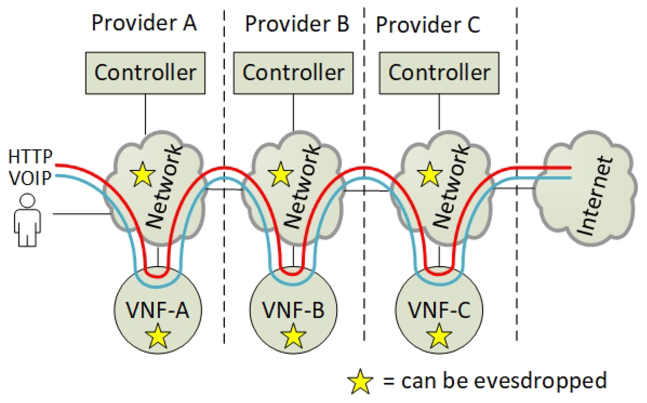
Figure 2 shows where end-to-end user traffic can be eavesdropped on in an SFC. NFV is designed to be flexible and simple where most intermediate NFV services are perceived as transparent network services. Hence, the common end-users are unaware of the potential of traffic eavesdropping in an SFC. In multi-operator and multi-tenancy NFV networks, we argue that end-users need to know which operators require access to their traffic. In addition, we assume that the end-users want to apply security policies to their SFCs, which would specify what type of SFC traffic each operator can access. We argue that the end-users require the flexibility of both allowing a subset of the VNFs to have access to all their data traffic, and letting other subsets of the VNFs have access only to a specific type of traffic. Currently, such traffic isolation within an SFC is not possible; end-to-end encryption is also not supported within an SFC.
This article introduces an architecture that isolates and encrypts SFC traffic between the different VNFs, which requires the automation of the encryption setup. Enforcing the network traffic through encryption services requires a new east–west protocol for network routing and for key derivation. Hence, this article also suggests a protocol and a procedure that can automate this dynamic routing and encryption setup.
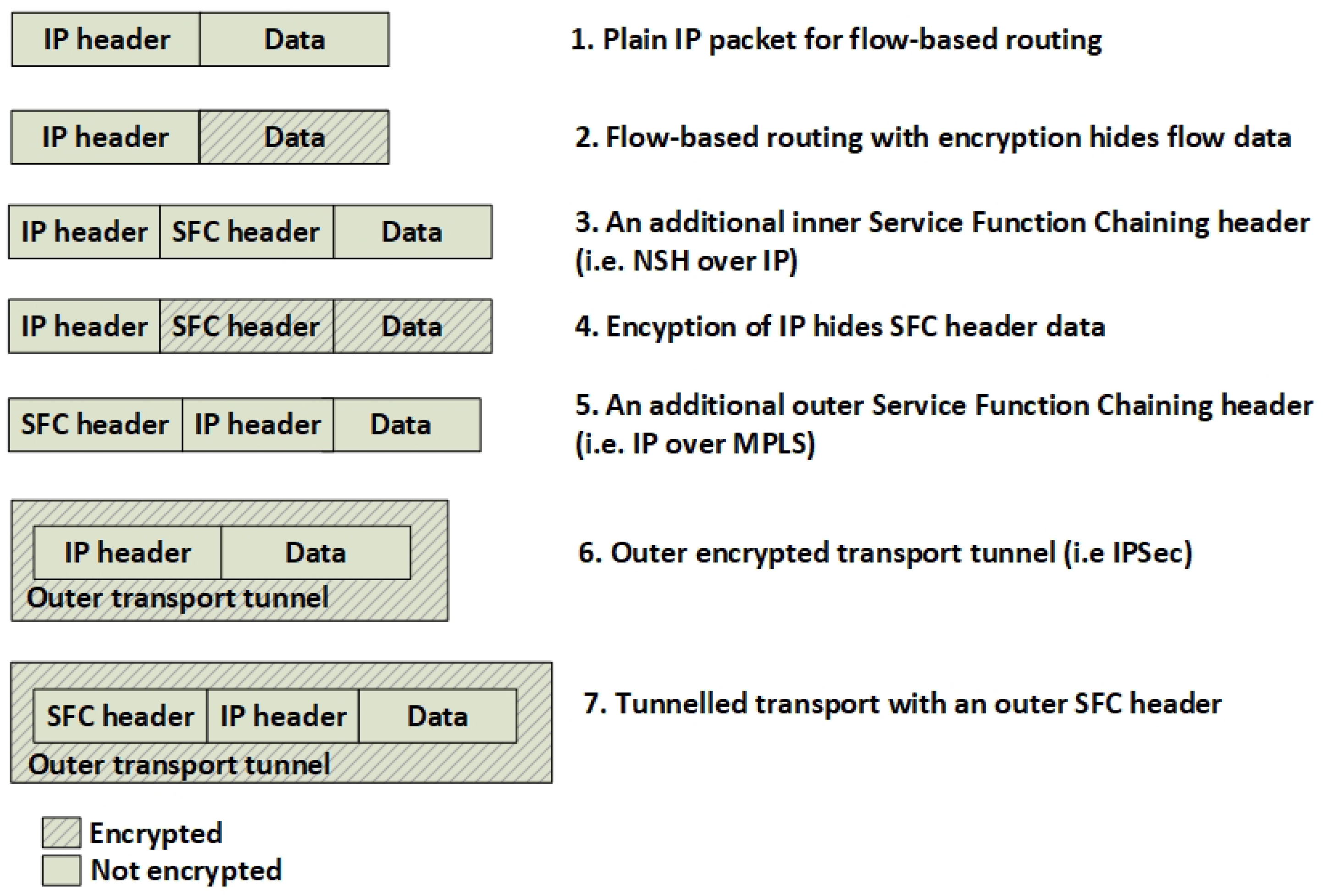
Figure 3 shows different approaches in routing SFC traffic. This is mainly reflected by plain flow-based routing (Figure 3(1,2)), the use of additional SFC headers (Figure 3(3,4,5)) or by using transport tunnels (Figure 3(6,7)). Running common encryption services on the Internet Protocol (IP) layer introduces an SFC routing problem because the packet encryption hides or changes the meta-data information such as the destination port inside the IP packet (Figure 3(2)). This lack of meta-data makes flow-based routing with i.e., OpenFlow difficult without using additional packet header tagging such as Network Service Headers (NSH) [1] or Multi-protocol Label Switching (MPLS) [2]. Hence, the packets must be classified before they are encrypted and a packet tag must be applied to the IP packet in order be able to route the packet correctly. Our solution to this problem is to put an SFC header in front of the encrypted packet and encapsulate it by a transport tunnel running between the NFV providers (Figure 3(7)).
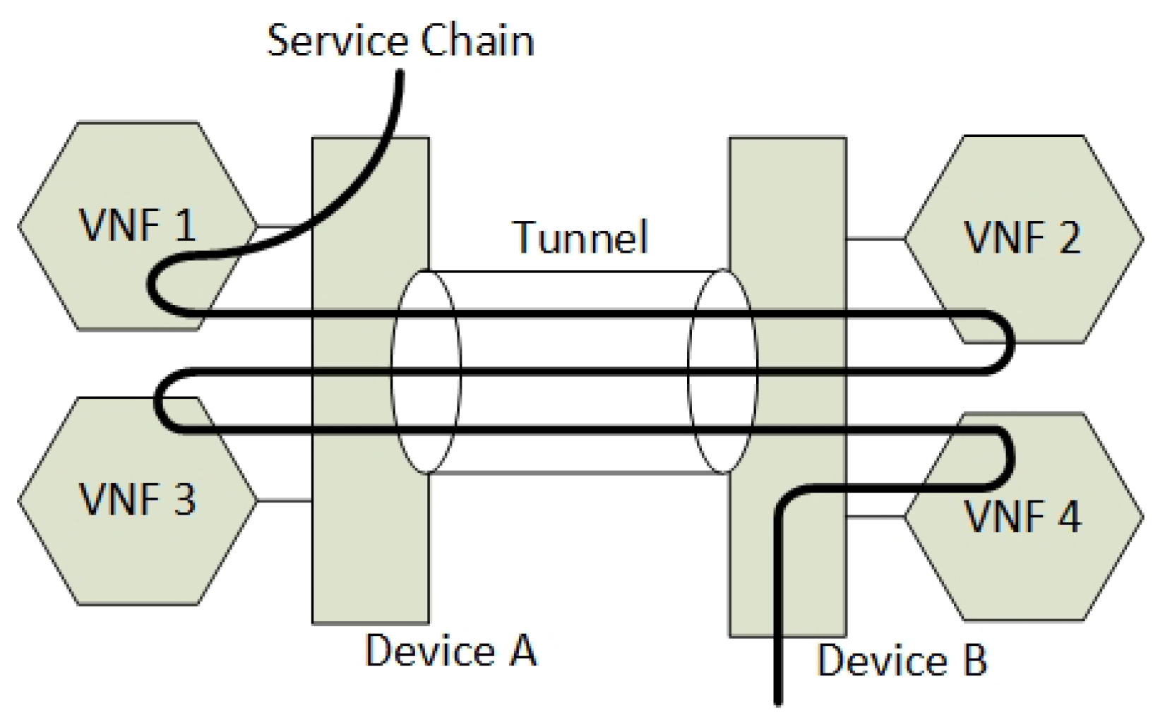
Another related problem when not using SFC headers such as NSH or MPLS is how to ensure the state of an SFC packet. Figure 4 shows that an SFC can traverse back and forth between two NFV Service Providers. The example shows how the network device B must know if an incoming packet from the tunnel has its destination to VNF 2 or VNF 4. Since the IP headers of the SFC packet normally do not change, the packet must be tagged by meta-data or be tunnelled.
This need for SFC packet headers excludes most SFC technologies that are not using additional SFC headers from being applied in combination with IP encryption. This also excludes other methods that do not allow the use of NSH or MPLS. Hence, this article focus on using NSH as both an SFC packet forwarding and a routing mechanism.
2. Related Work
Both our previous work [3] and other related research [4] have identified many technologies in order to interconnect NFV services across multiple service providers. The research shows that, due to a wide set of components and abstraction layers, the interconnection of interfaces between the provider domains can be archived in many ways [4]. From an orchestration layer perspective, the most common approach is to have a top-level single component that orchestrates subsystems. However, in addition to interconnecting the Service Providers through a common orchestration plane, it is also possible to offload the orchestration plane by interconnecting domains at other abstraction layers.
One method to interconnect Service provider domains is synchronizing the control planes between the providers to allow them to be perceived as one. For network control systems, all the network resources are perceived as one single SDN pool, while, for NFV, the Network Function Virtualization Infrastructure (NFVI) is perceived as one single pool [5] as well. Examples of such technologies are SDNi [6] or the Border Gateway Protocol (BGP). The problem with these methods is the dependency on the data plane, where different domains use different routing protocols or different types of SDN controllers. Another method is to provide an additional control plane abstraction layer that translates different control plane protocols to one standard such as the Forwarding and Control Element Separation protocol (ForCES) [7] or the Control Orchestration Protocol (COP) [4]. This introduces an additional overhead and also requires the involved partners to support the abstraction layer standard.
The European Telecommunications Standards Institute (ETSI) suggests interconnecting multiple domains on the Management and Orchestration layer with less focus on an east–west control plane protocol [8]. Furthermore, they aim to let the orchestration plane configure multiple control planes as they are multiple autonomous systems. Implicitly, ETSI aims to minimize the use of an east–west control plane protocol, while allocating the network intelligence and service routing on the orchestration layer. Their architectural guidelines [8] do not exclude a control plane to control plane protocol. However, a control plane protocol gives other opportunities that the orchestration layer does not support. Kulkarni et al. [9] shows that a control plane protocol such as Network Service Headers does provide an independent service plane, it opens up for exchange metadata of VNFs, and it enables the possibility to classify and tag packets independent of the other packet headers. This also aligns with the need for SFC headers when running encryption as stated in the Introduction section (Section 1.1). SFC protocols that support additional SFC headers such as Network Service Headers (NSH) and Multiprotocol Label Switching (MPLS) [2] can be used in combination with an underlay of existing encryption protocols such as Internet Protocol SECurity protocol (IPSec). If the SFC header is preserved unencrypted along the SFC, it is possible for the routers to do SFC routing decisions, according to the control information contained in these headers. This makes it possible to run encryption services in front of the VNFs and still preserve routing information in the data packets.
The idea of using such a control plane protocol reflects the work from the Internet Engineering Task Force (IETF), where BGP is used for exchanging route information for NSH [10]. This NSH BGP control plane specification from the IETF lays the foundations for the architecture presented in this paper. However, BGP does not yet contain any information about the setup of encrypted SFC channels, while it offers no details about how the integrity of the attributes can be protected [11]. We extend this specification by introducing new encryption attributes to BGP and new Key Management Services (KMS).
IETF has suggested one expired Request For Comments (RFC) draft on a mechanism that supports the integrity of NSH headers [12], but this does not support per-flow encryption nor automation between multiple domains. Therefore, we aim to extend the NSH header integrity check approach by introducing additional upper and lower control plane channels for scaling, automation and encryption. From the encryption perspective, no new protocols have been found for encrypting SFCs. However, associated encryption technologies have research potential. An upcoming technology such as the Software Defined Internet Key Exchange (SD-IKE) [13] opens up new possibilities by running individual encryption per flow that is controlled by an SDN controller. Currently, SD-IKE is specified for the use in a single controller domain only, enabled by OpenFlow (OF). It does not work between two different SDN domains because of a missing control plane protocol and the lack of common SFC flow identities [14]. However, if an SFC-aware control plane protocol between an SDN controller is developed for this technology, it is possible to use one common encryption engine that encrypts every SFC flow individually. Due to the lack of inter-domain communication standards of SD-IKE, the architecture proposed in this article uses an alternative approach. We propose that each VNF is connected to a standalone encryption service that is only used once in one SFC.
No further research has been found that discusses per-user encryption of SFCs. Neither have any protocols or related research been found that supports encryption setup or key exchange mechanisms between multi-domain VNFs.
3. The Architectural Model
In this section, we present the proposed architecture at the highest abstraction level (Model), discussing the required entities, their relations, and their high-level functionalities. As presented earlier, the proposed architecture aims at SFC isolation enabled by automation of encryption channels. The architecture is based on nested SFCs, utilizing BGP to announce domain-specific information about network controllers and their respective encryption services. This information is again used to negotiate encryption services and keys for the purpose of securing the nested SFCs, maintaining a clear distinction between packet forwarding and tunnel configuration. Hence, the main components in the proposed architecture are:
- Data-plane components for transitive SFC classification and forwarding. The SFC specification refers to these components as Classification Functions (CF) and Service Function Forwarders (SFF), that needs modification to support nested SFCs.
- Control plane components for information sharing, with BGP and key distribution for encryption setup. The main components here consist of a Software Defined Network Controller with the BGP capabilities.
- Management and Orchestration (MANO) applications, in order to orchestrate and provide encryption services to automate the set up of VNF isolation.
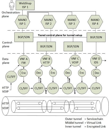
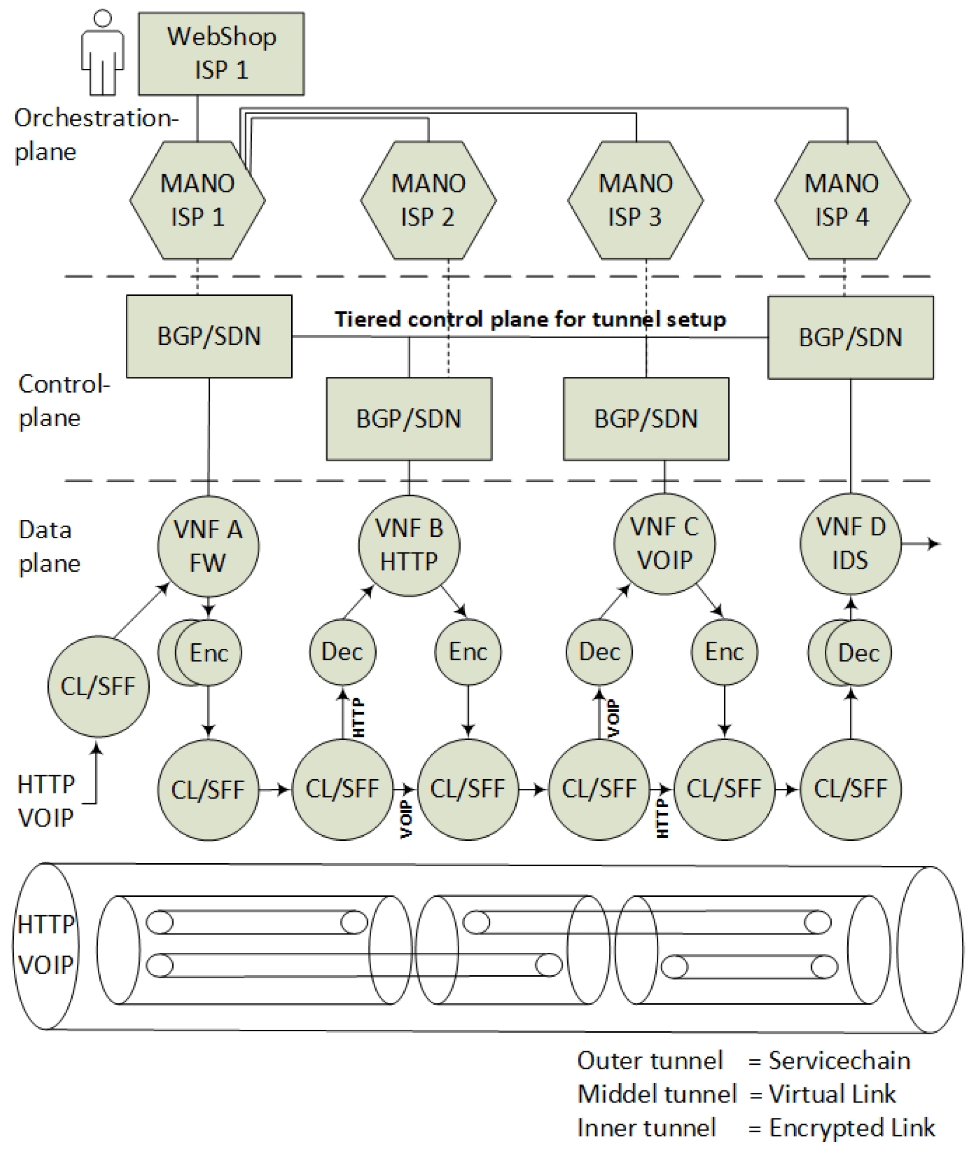
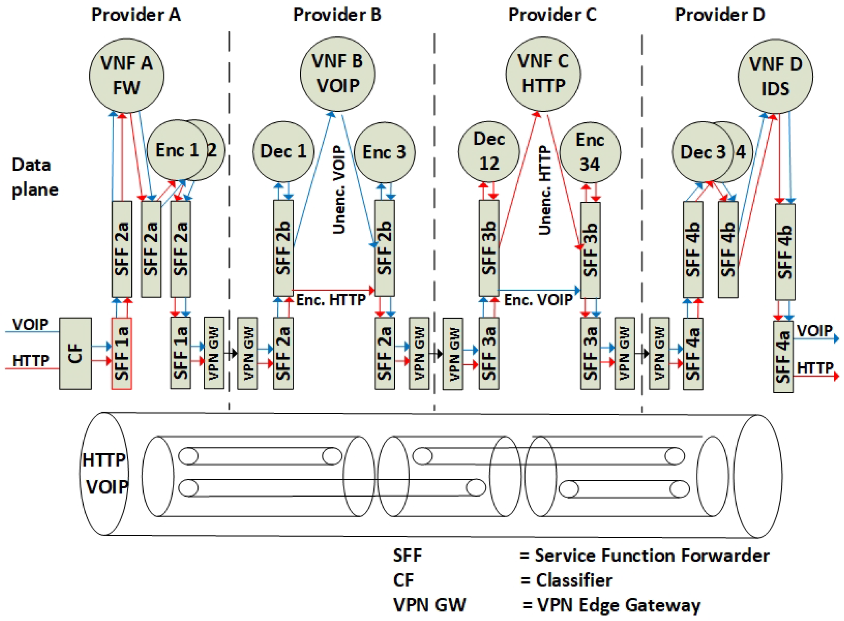
The architectural model in Figure 5 exemplifies how VNFs in an SFC can be isolated and encrypted in accordance with the proposed architecture, conforming to the SFC specifications [15]. This example reflects data plane packet forwarding of four Service Providers in a modular SFC. In summary:
- The incoming data packets of the Voice Over Internet Protocol (VOIP) and the HyperText Transfer Protocol (HTTP) are classified according to the specific (VNF A>B>C>D) SFC path. Since the SFC path is predetermined by distributed route tables, the SFC headers are added to the packets.
- Due to VNF isolation requirements, the packets are classified and forwarded based on two layers of SFCs. Hence, the first classifier is also adding the second isolating SFC header. For this example, two inner SFCs are established: one for VNF A>B>D–HTTP components and one for VNF A>C>D–VOIP components. This ensures that, with respect to routing, VNF B and VNF C are isolated from each other.
- To ensure the encryption of the packets, each hop in the inner SFC paths must be encrypted. Hence, the network controller is distributing the SFC paths to traverse sets of pairwise encryption services. The network controller is also distributing the encrypting keys per link.
- The packet forwarding continues with consecutive encryption > processing > decryption sequences, in accordance with a distribution of pairwise keys among the providers, and with SFC header modification per hop. Pushing and popping of additional SFC headers ensure that the SFC path is maintained. The SFC path is therefore an end-to-end encrypted tunnel, implemented as interconnected chains of hierarchically encrypted links, where, in the presented example, providers A-B-D can access only the HTTP component, and providers A-C-D only the VOIP component of the SFC.
In order to provide the required functionalities for these operations, the following modifications have to be integrated into the overall architecture.
3.1. The Data-Plane—A Hierarchy of SFC Headers
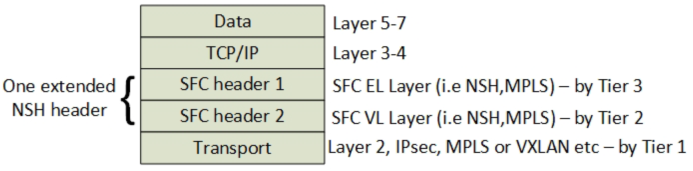
To be able to isolate and encrypt traffic between different VNFs, an encryption service has to run at all ends of every VNF in the SFC. Furthermore, to ensure compatibility with the SFC specification [15], the encryption services are separated from the VNF and the Service Function Path (SFP) itself. Hence, the proposed architecture introduces additional encryption tunnels in the SFC model, which are identified as inner SFC tunnels, and defined by the SFC header 1 (Figure 6), while SFC header 2 corresponds to the original SFC header in accordance with the SFC specifications [15]. It must be noted that the Virtual Links (VLs) are layered headers and are not implemented as communication tunnels, but they can be perceived as virtual tunnels from an architectural perspective. In practice, the SFC layers are placed below the IP layers in order to enable IPsec encryption. As previously mentioned, this is because encryption of an IP packet with SFC headers inside would hide both SFC header and the classification data [16].
We define the SFC header 1 to constitute the Encrypted Link (EL) and to let the SFC header 2 define the Virtual Link (VL), while the transport layer is named the Transport Link (TL). All of these packet headers need routing information associated with them, which is defined by a tiered control plane (see next Section). From an OSI-model perspective, we define the two new SFC layers to belong between layer two and layer three (Figure 6). The Transport layer is according to the SFC specification [15] referred to as the layer that transports SFCs. Here, we define the transport layer to be an IPsec tunnel.
The SFC header 1 is always associated with an Encrypted Link that consists of an inner SFC with one hop only. Due to the static nature of the inner SFC header 1, this information is placed as an extension of the original SFC header 2 and not a next-protocol header. For SFCs enabled by NSH headers, this means that one NSH header can contain both SFC 1 and SFC 2 headers. Section 6 shows how the original SFC header of NSH is extended to include inner SFCs identifiers by introducing a new type value of the NSH header.
3.2. The Control Plane—Tiered Tunnel Automation
To enable the automated creation of the encryption tunnels, a common control plane is required across the VNF Providers. This is similar to the current use of BGP as a global common control plane for internet traffic routing among Internet Service Providers. Such a control plane for NFV service chained traffic must support the exchange of service capabilities, flow-specific routes, and service chains. In principle, keys and VNF associations must be distributed between every Service Provider contributing to the SFC, in a per-hop > per-NFV service > per-user basis, while sharing such information globally imposes scalability limitations.
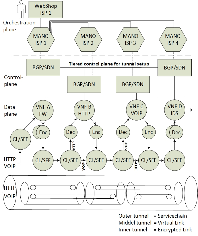
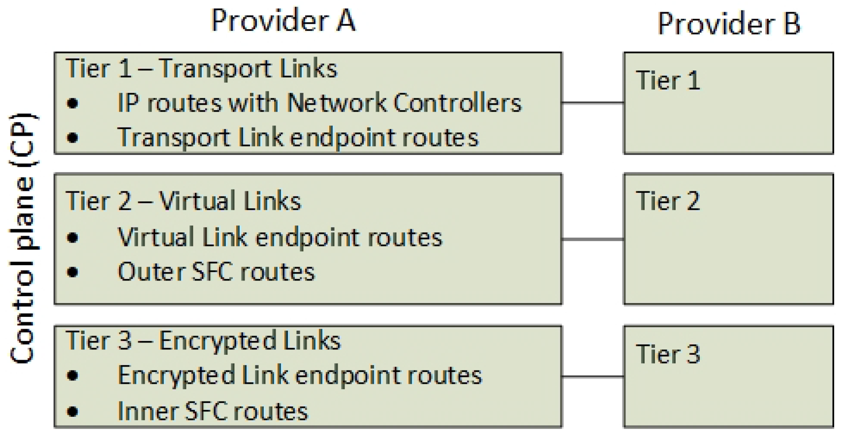
Therefore, the control plane is defined architecturally as a three-tiered control channel with a key set-up mechanism. Figure 7 presents the tiered control channels within the control plane, between the providers A and B of the previous example. This tiered concept follows the IETF SFC [15] standardization and the BGP control plane RFC for NSH [10]. However, it extends the functionality by introducing three tiers of control plane routes that reflect the hierarchy of data plane headers. Next, Tier 1, 2 and 3 functionality is explained.
3.2.1. Tier 1—Datacenter Sharing
The first tier exists in a global IP Virtual Private Network (IPVPN) where the NFV providers share their control plane attributes such as the network controller and their external Transport Links (Figure 7). The address of each network controller is announced to all peer controllers in the VPN, along with routing capabilities and connection properties in order to define how to connect to them. This information about the association between domains and their Transport Links is required in order to ensure routing support of SFC headers between the domains. In addition, since encrypted tunnels to a destination VNF are configured on the control plane, each controller must know which controllers to connect with, in order to set up the Virtual Links (VL) and consecutively inner Encrypted Links (EL).
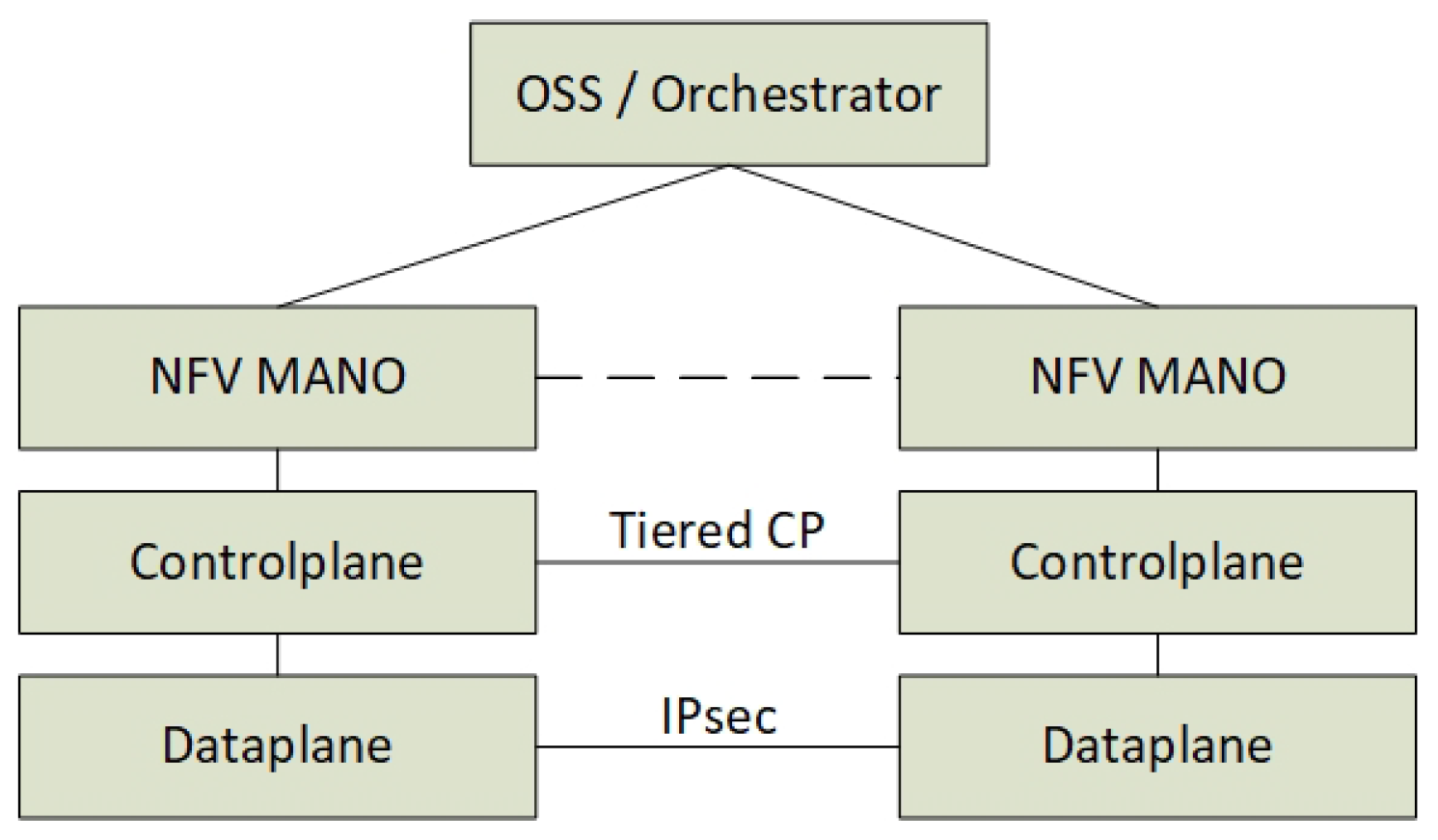
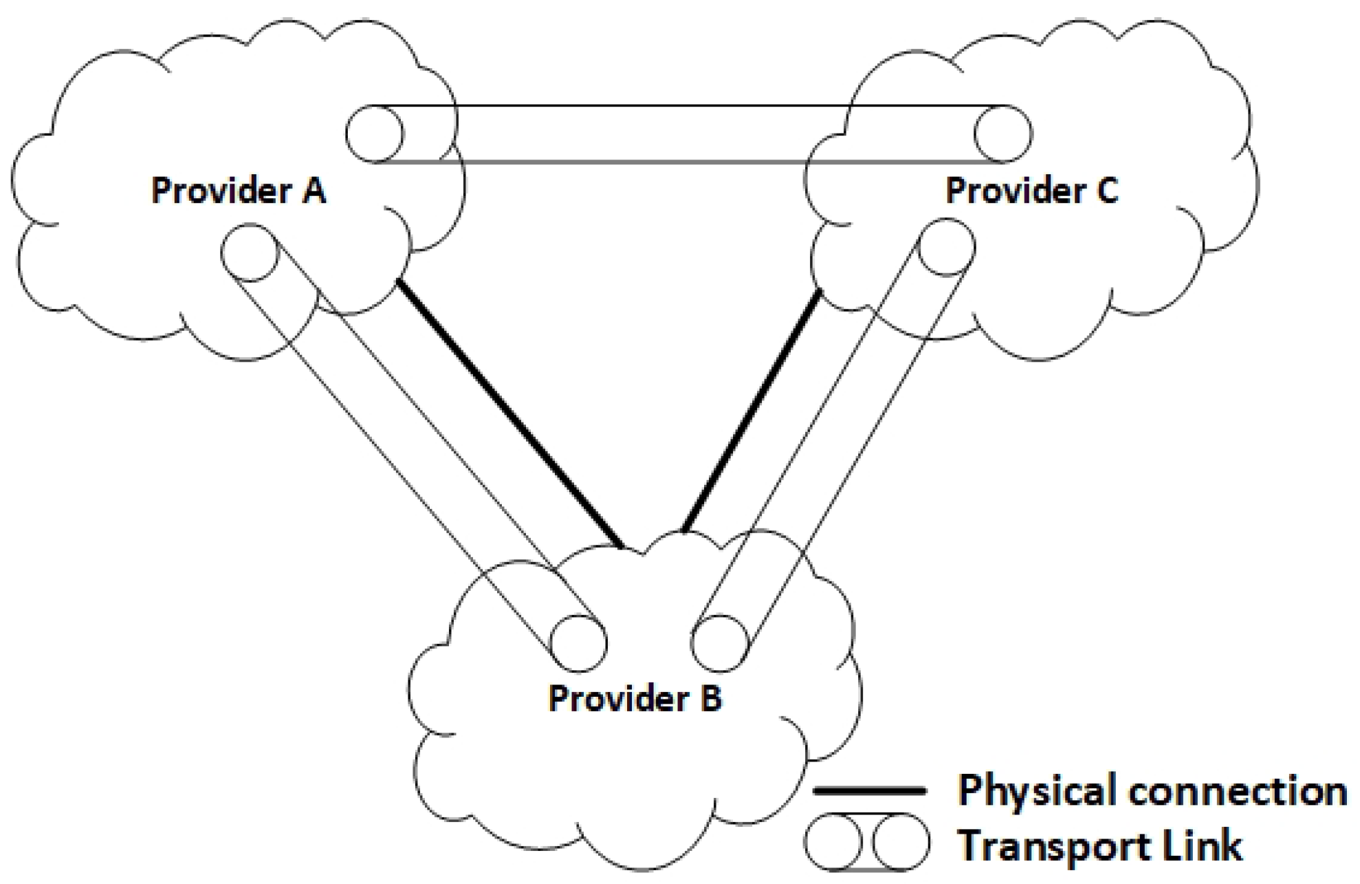
For this purpose, every peer in the VPN serves as a proxy for the aforementioned information to others with normal BGP route distribution algorithms, so this information can be further used to set up a full mesh of Transport Links between datacenter domains (Figure 8). Figure 8 also shows an example of Provider A and C establishing a Transport Link between them based on the route information sent by proxy from Provider B.
A new multi-protocol BGP (mBGP) [17] address family is required because the BGP peers announce new types of IP routes that must not be mixed with regular BGP IP routes. This applies both to Transport Links and Network Controller routers. Consequently, new Address Family Identifiers (AFI) [17] and new Subsequent Address Family Identifiers (SAFI) [17] have to be defined by the Internet Assigned Numbers Authority (IANA), to ensure a global identification of which IP routes a network controller is responsible for. Furthermore, the use of a standard Resource Public Key Infrastructure (RPKI) [18] with BGP to secure the origin of the BGP speaker is required for distributing the public keys of each network controller, in order to provide identification, confidentiality and integrity of the network controllers and distributed routes.
3.2.2. Tier 2—The Announcements of VNF Locations and SFCs
The second Tier is a full mesh of one-to-one control channels between all network controllers involved in an SFC. The channels are utilized to exchange information about the route locations of the VNFs that reflect the SFC header 2 routes. The BGP announcements are split into two parts. The announcement of the location of the VNFs and the announcement of the SFC.
The full mesh of Transport Links allows BGP route distribution of flow-specific routes to be scaled down, since the routes are transmitted only to relevant network controllers, according to the network topology established in Tier 1.
3.2.3. Tier 3—The Announcements of Transitive SFC Routes and Encryption Service Locations
Tier 3 is responsible for establishing and managing the inner SFC Encryption Links. The route distribution is similar to Tier 2 and is also a process consisting of two parts. The announcements of the location of the encrypting services and the SFC announcements of the next hops in the SFC. These routes are announced over a separate Tier 3 BGP peering interface. The Tier 3 routes must be clearly distinguished from Tier 2 routes. Hence, a new BGP address family (AFI and SAFI) is also suggested to be defined for this Tier. The components of Tier 3 are therefore similar in nature to those of Tier 2, but they serve a distinct purpose and therefore must refer to a new address family.
The SFC header for Tier 3 is in this context not SFC subsystems such as nested SFCs where the inner SFCs belongs to a sub-chain of SFCs in RFC 7665 [15]). The Tier 3 SFCs are transitive, meaning that they always coexist with the upper SFC layer and contribute to routing decisions for both Tiers 2 and 3. To differentiate SFC subsystems from inner SFCs, the Tier 2 SFC header must also contain information about the type of the next SFC header. When using NSH, this means that both inner and outer SFCs must exist in one NSH header. Hence, it is a header extension and not a next protocol header.
Finally, an important prerequisite is that the encryption services are already running before the announcement of the Tiers 2 and 3 SFCs. Hence, Tier 3 SFC announcements need to be announced before Tier 2 SFC announcements. This also reflects the fact that information about Tier 3 SFCs must exist in Tier 2 SFCs, which is explained in the Protocol and Interface Section 5.
3.2.4. Encryption Automation
The control plane is also responsible for the setup of encrypted channels between the VNFs. In this architecture, we suggest automating the exchange of encryption keys. We define that it is the origin Service Provider in an SFC that is responsible for key distribution and tunnel automation. A Key Management Server on the control plane is defined to distribute the setup of the secure channels. The key distribution depends on the SFC and is therefore dependent on the order of the VNFs and how they are routed. Hence, a key distribution protocol that supports dynamic endpoint configuration and the negotiations of encryption keys from a trusted third party authentication server is needed. Section 5 suggests a simplified prototype of such a protocol where two random endpoints contact a third party server to receive instructions on how to establish a Security Association for IPsec.
3.3. The Management and Orchestration (MANO) Plane
To enable the automated VL encryption and VNF isolation with network redundancy, the architecture suggests having the network intelligence in the control plane, which implies that the Management and Orchestration plane (MANO) is less declarative about the network configuration. Instead of relying on the MANO to instruct the control plane about the locations of the VNFs and their corresponding encryption services, the control plane directly utilizes BGP and Key Management Services in order to configure the network dynamically. This enables the MANO to be less declarative about the network configuration, and enforces the control plane to have imperative services that can be dynamically reconfigured based on physical changes without MANO dependencies.
We simplify the ETSI reference model and only focus on new top-level services on the orchestration plane. The services include enabling VNF isolation and encryption that are the only parts that are relevant for the control plane components. Hence, the architecture is focused around the control plane where the ETSI MANO components such as the Virtual Infrastructure Manager (VIM), the VNF Manager and the orchestrator are not taken into account. The NFV MANO components are aggregated into one orchestration plane application, which enables a set of service requests, which are discussed in the next section.
4. Services in the Architecture
This section discusses the services that constitute the proposed architecture, beginning with the end-user services enabled by the orchestration plane, followed by the service components on the control plane and the data plane.
4.1. Service Components on the Orchestration Plane
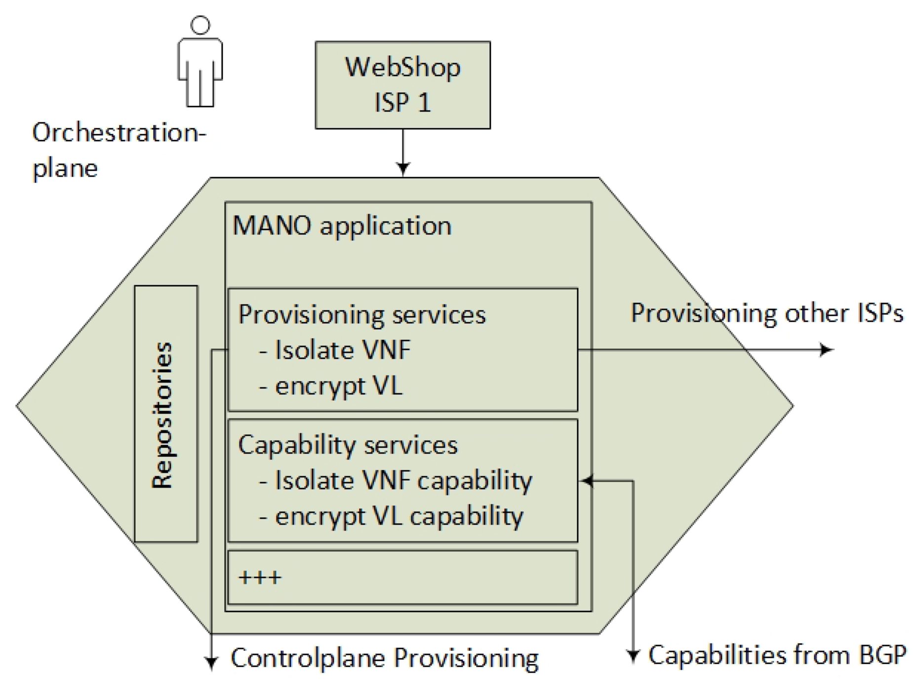
The end-user orders a set of services (VNFs) from the ISP in a web portal, and while being unaware of the data-center location of each service, he wants to ensure that integrity and confidentiality are preserved in the SFC between the VNFs. The end-user requires both checking if the infrastructure is capable of delivering the services and also placing an order of service provisioning. This implies that the end-user can do four new types of service requests provided by the orchestration layer with respect to isolation and encryption: 1—Request of encryption capabilities per VL, 2—Request of isolation capabilities per SFC, 3—Request of provisioning an SFC with encrypted links and 4—Request of provisioning transitive encryption services to enable VNF bypass in the SFC (Figure 9).
These simplified end-user services are utilized in an application such as a webshop in the Operation Support System (OSS) domain (Figure 9). The practical result of such service requests ends up in a list of VNFs connected to an SFC, which also includes an inner SFC specification. These are called Network Service Descriptors (NSD) [19] and are stored in a repository. This architecture focuses on hierarchical SFCs and encryption services, assuming minimal modifications of the ETSI model in the form of NSD extensions. However, modifications of the NSDs are required in order to support a description of encryption services (encrypting VNFs). Additionally, an extension of the NSD describing the VNF Forwarding Graph Descriptor (VNFFGD) is needed, in order to support hierarchical SFC descriptors. A type extension of the Virtual Link Descriptor (VLD) is also needed to describe inner Encryption Links for Tier 3. The orchestration application provisions the VNFs towards all relevant Service Providers, as well as provisioning backup VNFs for redundancy, while it distributes the relevant identifiers during the VNF instantiation. Furthermore, the control plane is responsible for selecting what VNF instances will participate in the SFC. The necessary NSD extensions are described in the Protocol and Interface section (Section 5). In summary, the orchestrator maintains the following functionality:
- Interpret end-user requests of VNFs and SFC in order to create the NSDs,
- Calculate where it is most efficient to run the VNFs,
- Consider any VNF constraints,
- Verify that it exists a Transport Link between every Service Provider that participates in the SFC,
- Ensures that the encrypting VNFs are co-located with normal VNF during provisioning,
- Provision VNFs at all Service Providers,
- Generate a pass-phrase (PSK) per VNF instance to enable authorization of the VNFs. When the VNF is provisioned, this key is submitted as a VNF application parameter.
4.2. Service Components on the Control Plane
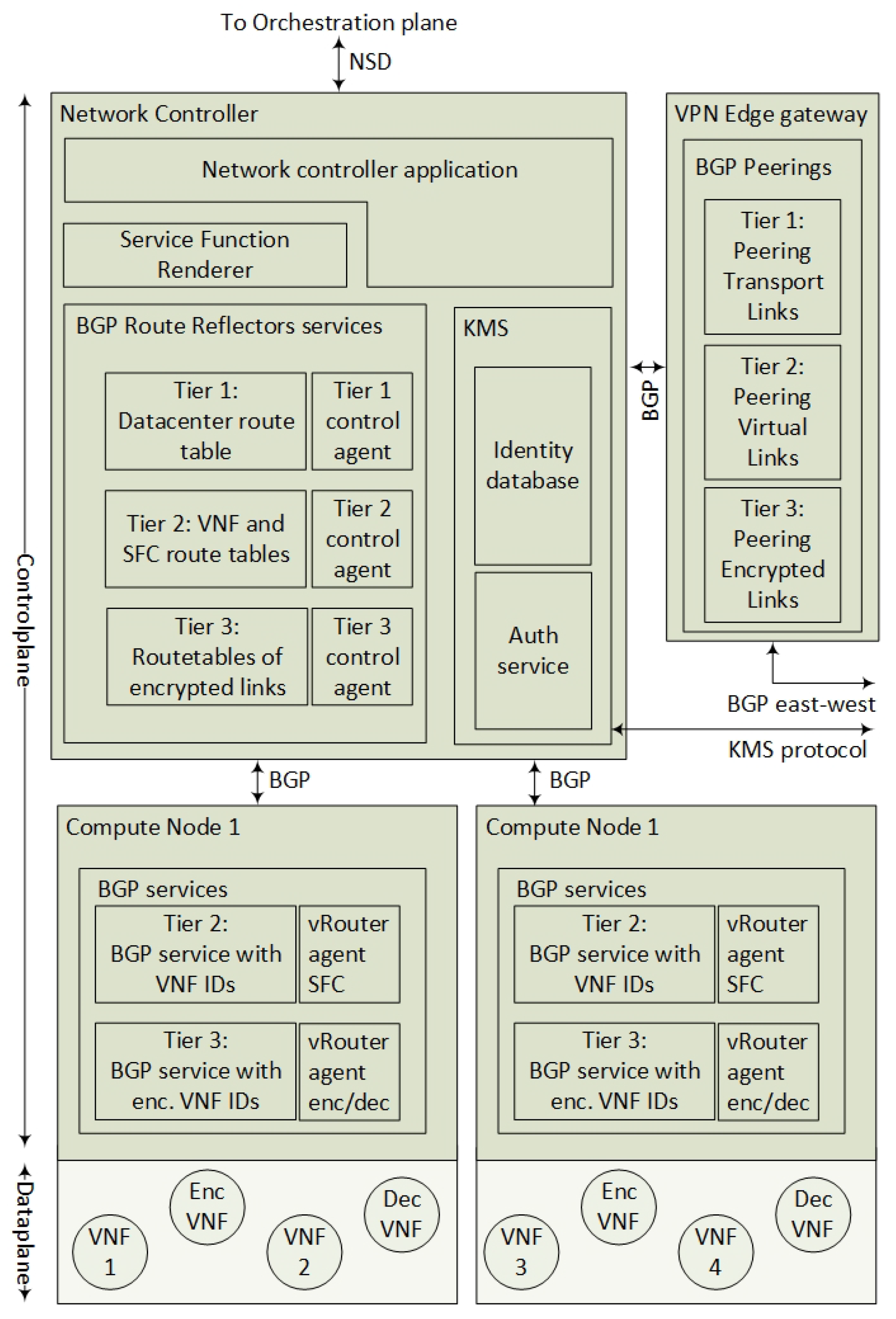
An interconnected multi-domain control plane protocol is the main contribution of this article. The most important services in the control plane protocol are the BGP services that exchange SFC route and the encrypted path information (Figure 10). This section explains the route distribution services and the surrounding control services.
The two main components of the control plane are the network controller and the Compute Node (Hypervisor) BGP services. The architecture is not based on traditional imperative SDN such as OpenFlow or distributed Open Virtualized Switches (OVSs) on the Compute Nodes, but it uses a declarative SDN method by the use of the BGP route distribution. Hence, the network controller is distributing SFC flow routes over BGP in order to inform all Compute Nodes about how to forward SFC packets. Every Compute Node announces its connected VNFs in order to let the network itself calculate the correct SFC paths. Similar to the BGP control plane for SFC [10], every Compute Node acts as a BGP speaker to announce its connected VNFs. Since the network controller knows the location of the VNFs, it can distribute the SFCs for both Virtual and Encrypted Links to every Compute Node. This section explains the functionality of this BGP service, how the edge VPN gateway connects the remote Service Providers and how the Key Management Server (KMS) can automate the setup of tunnels.
4.2.1. The Network Controller
The network controller application is the main controller of all other services. It holds a control application and a Service Function Renderer that interprets the SFC provisioning. This architecture requires that the NFV orchestrators have provisioned all the VNFs, while the network controller is responsible for the network provisioning. According to the SFC RFC [15], the first SFC controller is responsible for setting up the SFC. The Service Function Renderer service selects the instantiation of an SFC path. Service Functions in an SFC may become unavailable or the physical constraints may alter the most efficient path. Hence, the SFC specified by the user can be different from the instantiated SFC path (aka Rendered SFC). For example, if a VNF is down and a policy allows the VNF to be bypassed, then the corresponding Encrypted Links must also be bypassed. In this architecture, the network controller is simplified for supporting the following services:
- Mapping the instantiated VNF IDs to their Compute Node locations,
- Populating the KMS server with identities (see Section 4.2.4),
- Populating the Tiers 2 and 3 agents with the rendered SFC,
- Orchestrating Transport Links, Virtual Links and Encrypted Links,
- Recalculating SFCs for optimization or VNF bypassing during a network or Compute Node failure.
4.2.2. The Tier 1 BGP Service
A Service Provider establishes a peering with a remote data-center by a contractual Service Agreement. This agreement is established by an abstract level on the orchestration layer and is practically set up as BGP peering between the Service Providers. This article recommends having the BGP peering in a private IP-VPN, but, theoretically, it can be a public Internet connection with extended BGP features. Next, dynamic configuration attributes such as the network controller type, network controller address and data-center to data-center Transport Link are shared over this BGP peering. This information gets distributed to every BGP agent in the network. The second stage of the Tier 1 setup is to establish data-center to data-center Transport Links that are normally set up using VPN connections. A VPN link defines the Transport Link between data-centers, which ensures that the underlying network is transparent to packet forwarding and that does not require intermediate network elements to be able to read SFC headers. The architecture suggests using one VPN gateway to terminate all Transport Links.
From the SFC routing perspective, the VPN gateway is the next hop for SFC packets going to a remote data-center. The next hop is determined by the VNFs locations of which are distributed by BGP in Tier 2 (Section 4.2.3). For direct peerings, this VPN tunnel is optional. The main purpose of this BGP service is to inform all network controllers about remote Transport Links (Provider A must know that a Transport Link exists between providers B and C). This means that, if no VPN tunnel is needed, the Edge gateway still has to announce that the Transport Link is established in terms of a direct peering such as a direct cable. The Tier 1 agent can verify that the full mesh of Transport Links exists, while it holds a table of the domains (AS numbers) that it is directly or remotely connected. The Tier 1 control agent is responsible for:
- Sharing network information over BGP,
- Instantiating Transport Links,
- Populating the Tier 1 BGP with Transport Links,
- Serving an Application Programming Interface (API) towards the orchestration layer for end-user services regarding capabilities of encryption and isolation.
4.2.3. Tiers 2 and 3 BGP Peerings
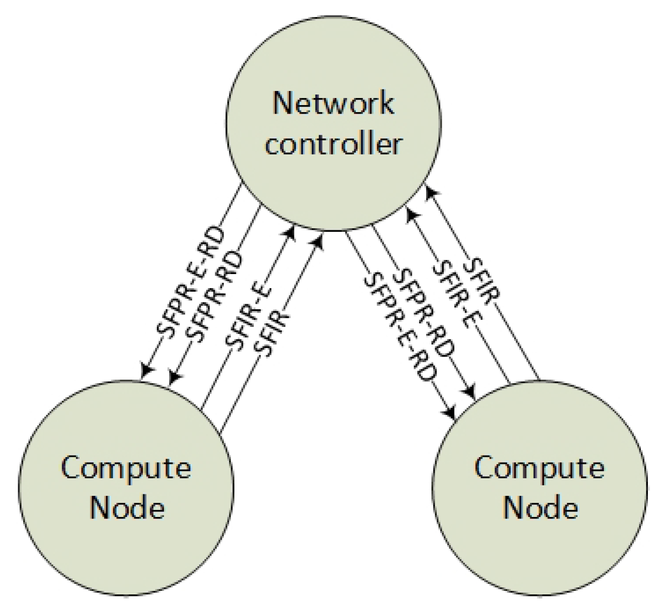
The BGP control plane for SFC [10] intends to let every Compute Node announce their virtual services (VNFs) as Service Function Instantiated routes (SFIR). In order to let the network itself calculate the correct SFC paths, the Tier 2 control agent can inject the Service Function Path Routes as a Route Distinguisher (SFPR-RD) and distribute them to the Compute Nodes. This route distribution enables each virtual router agent in the Compute Node to calculate the next hop in the SFC. Hence, the Compute Nodes virtual Tier 2 agent can calculate and change the SFC headers Service Path Index (SPI) field, in order to reflect the next hop in the SFC.
By introducing an additional layer of Encryption Links (Tier 3), each Compute Node also needs to distribute information about their encryption services. The encryption VNF identities announced from the Compute Node we define as Service Function Instantiated Routes with encryption services (SFIR-E). Accordingly, the controller announces the corresponding SFCs that contain the routing information about the encrypted SFC and its relation with the outer SFC, namely the Service Function Path Routes with Encryption Route Distinguisher (SFPR-E-RD) (Figure 11).
The main roles of the Tiers 2 and 3 network controller agents, are to translate the rendered SFC into BGP routes. Since BGP also can contain redundant routes, the redundant routes are also calculated and distributed according to what redundant VNFs have been provisioned. An additional functionality of the Tiers 2 and 3 control agents is to serve the encryption setup procedure with location information. The automated Encryption Link procedure is based on pre-provisioned VNF services that are configured to contact a common KMS service in order to exchange their encryption keys. Hence, the route messages of SFPR-E-RD must be populated with encryption information (public keys) by the Tier 3 control agents. The control agent makes sure that the VPN tunnel is set up before the route is announced by polling information from a Key Management Service. In summary, the Tier 3 control plane is responsible for:
- Distributing route information of how to route the SFCs to other Compute Nodes—this also includes redundant routes,
- Translating the SFC into BGP messages,
- Serving the KMS server with information from BGP, such as identities and encryption keys.
4.2.4. Distributed Key Management Services
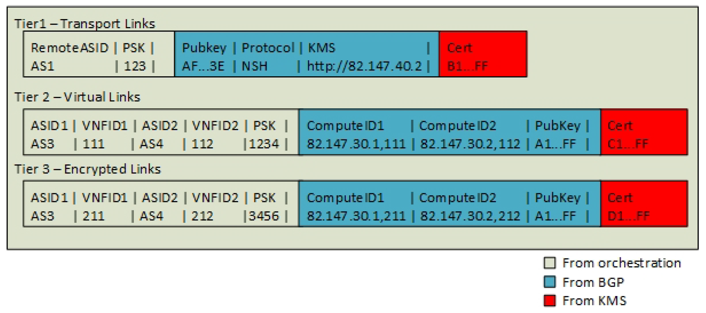
One key problem in the current NFV architecture by ETSI [20] is that no trusted party is defined for the case when multiple Internet Service Providers want to agree on a shared pair of keys. Furthermore, there is no domain name system, in order to locate the VNFs in order to use URL identities and keys such as SSL. However, the BGP announcements enable the Service Providers to share a Key Management Server (KMS) and to announce the public keys for every peer. We define that the Service Provider that originates the SFC manage both the SFC and the KMS server for all VNFs in an SFC instance. We define the encryption endpoint identities as the endpoint routes, namely Tier 1—Transport routes from VPN gateways, Tier 2—SFIR and Tier 3—SFIR-E. The Key Management Server holds a mapping of the pair of routes that constitutes these links. In the example, the endpoint RD = AS3:82.147.30.1,211 is paired with the endpoint RD = AS4:82.147.30.2,212 and together they form an Encrypted Link. For Tier 3, the KMS server is responsible for pairing these endpoint identities and mapping them to a corresponding IPSec Security Association (SA). The control plane application populates an “identity table” with the basic information of the domain (AS number), the VNF ID and the VNF provisioned PreShared Key (PSK). Dynamic information such as the KMS server and the Compute Node locations are populated from BGP. When this information is in place, the KMS server populates the table with a certificate (Figure 12). Note*: Tier 2 encryption and VNF authentication are considered redundant if Tier 3 is in use. Hence, Tier 2 encryption can be skipped if Tier 3 is enabled.
Tier 1 authentications use the remote AS as the authentication identity, while Tiers 2 and 3 use a concatenated string of domain (AS number), Compute Node and VNFID as the authentication identifier. For example, AS1:82.147.30.1,111. Note*: The global VNFID is not sufficient as an identifier since VNF migration to another Compute Node requires the keys to be changed.
For Tier 3 authentications, there is a clear KMS server authority that is assigned by the origin Service Provider in the SFC. Tier 1 authentications have, on the other hand, two potential KMS servers. By design, the first Service Provider that needs an SFC to a remote Service Provider initializes the connection. If both Service Providers instantiate a VPN tunnel simultaneously, two Tier 1 VPN connections can exist. BGP then automatically selects the most preferred transport route. Therefore, the Tier 1 control agent can optionally shut down the second tunnel.
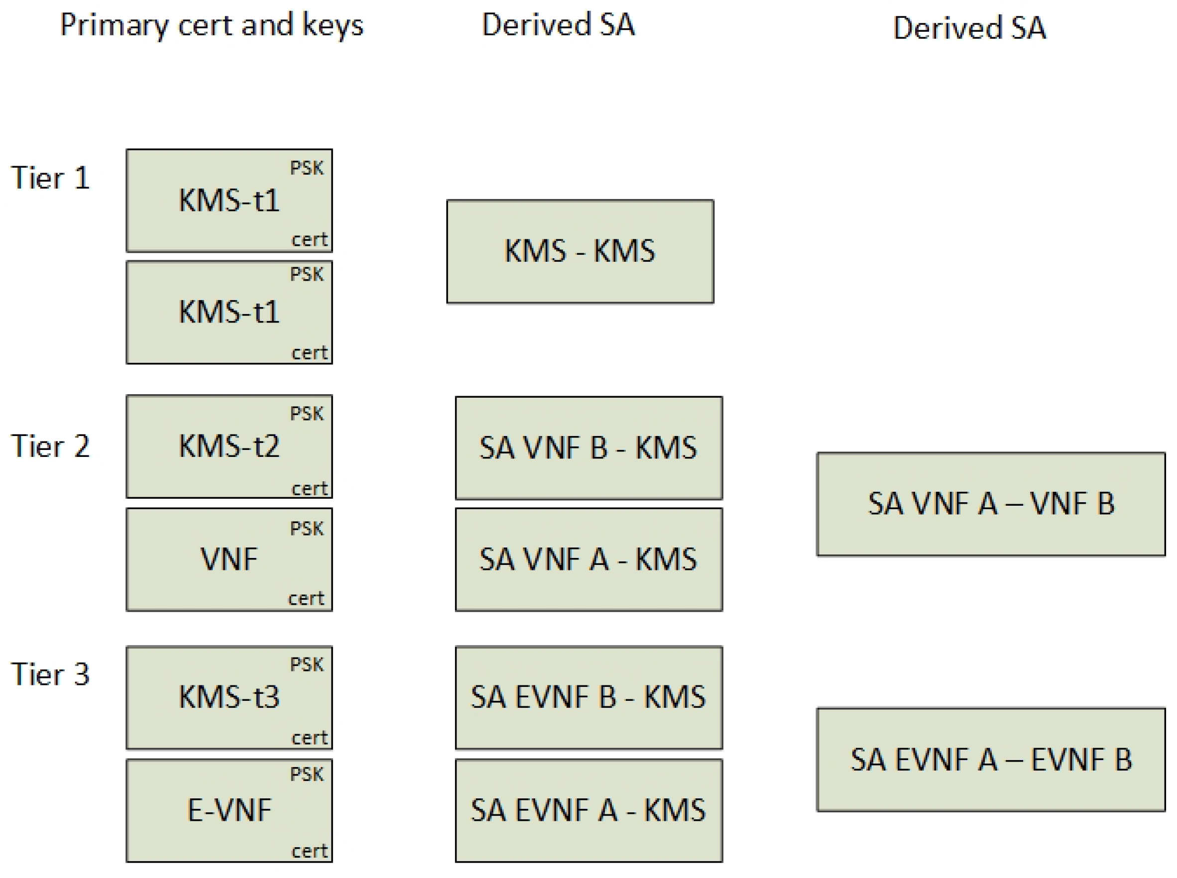
The KMS controls all the keys in the architecture. It contains the primary keys that are set up during VNF provisioning and it derives dynamic keys for the setup of secure channels. Common for all tiers is that two pairs of public and private keys are used to set up a secure connection between the peer, while a shared secret (PSK) is used to authenticate the peers. For the Tier 3 encryption link, an additional SA is derived according to the KMS protocol explained in Section 5.2.5.
Figure 13 shows a summary of the different keys that can be used. It shows that every VNF gets their unique certificate and authentication key during provisioning that corresponds to a unique KMS server certificate and an authentication key (PSK). The SA between the VNF and the KMS is established from these keys. Furthermore, the SA directly between the peers is instantiated dynamically over the existing SA between the KMS and the VNF. These are SA that are dynamically derived from the primary keys from the KMS and VNFs.
The main functionality of the KMS server can be summarized as:
- Give two random endpoints (VNFs) instructions about how to set up a secure IPsec transport mode channel between them,
- Authorize both endpoints based on their identifiers, a PSK and their certificates,
- Serve the setup of Encrypted Links, Virtual Links and Transport Links by a key exchange protocol.
4.2.5. The Edge VPN Gateway
To enable the automated establishment of data-center to data-center Transport Links, an Edge VPN gateway is used for this purpose. Because this gateway has the responsibility of establishing Transport Links, it needs a southbound configuration interface towards the network controller. This configuration consists of a tunnel interface that includes a pointer to a KMS server. However, the VPN configuration can also consist of a full IPsec tunnel configuration defined by the orchestration layer or it can also be configured manually. The network controllers southbound configuration interface to the External VPN gateway is a domain specific choice, where RESTconf [21] or Command Line Interface (CLI) are most common and recommended to use. Furthermore, if a VPN tunnel setup with a KMS server configuration is possible, this is announced over the Tier 1 BGP peering. The External VPN gateway contains BGP peering interfaces for all tiers. This enables both an exchange point of SFC routes between the Providers and it makes the VPN gateway capable of routing SFC packets.
It is optional whether the Tiers 2 and 3 peerings are established over the VPN tunnel or if it is a multi-hop BGP peering. However, from a security perspective, the peering is more protected if it runs over the VPN connection. It is also optional if the Tiers 2 and 3 peerings run as one or two peering instances. Since they use different address families, it is preferable to use one peering. To enable the scaling of Tiers 2 and 3 routes, it is suggested to use a BGP route filter to only allow direct peers to be announced over the BGP link. This means that Provider A only receives Provider B SFIRs from the Provider B peering, where Provider B not will proxy Providers C SFIRs to Provider A. In summary, the Edge VPN gateway must be able to:
- Dynamically establish the Transport Link to other data-centers by terminating VPN interfaces,
- Route SFCs to the corresponding Transport Links,
- Filter SFIR and SFIR-E routes for relevant peers.
4.3. Service Components on the Data Plane
Figure 14 shows the data plane services running on the Compute Nodes. They consist of Classifier Functions (CF), Service Function Forwarders (SFFs), Encryption Services, VPN gateways and VNF applications, which will be further explained in this section.
4.3.1. Classification
Before a packet enters the NFV domain, it must be classified according to what SFC it belongs to. Typically, the classification is based on source IP address and destination (TCP/UDP) port, but it can also be based on any attributes of layer 2 or layer 3 headers. The classifier adds the SFC headers to the packet, utilizing a look-up table of mappings between SFC identifiers and packet classification attributes. Because the packet encryption hides the TCP/UDP ports, this architecture assumes that it is only the classifier in the beginning of an SFC that does the packet classification based on non-SFC headers. Furthermore, SFC forwarding requires that the SFC header uniquely identifies the packet for each SFC hop. On the other hand, SFF proxies require that the SFC headers are removed before the data packets entering the service functions. In order to be compliant with SFF proxies, uniquely identifiable interfaces between the service functions and the SFFs contribute to the re-classification of SFC traffic that is traversing an NSH proxy.
The result of the classification is a combination of inner and outer SFC identifiers that corresponds to traditional classification rules based on IP. For example: Source IP 82.147.41.42 with destination port 80 is mapped to SFC header 1 with ID 10 and SFC header 2 with ID 20, while source IP 82.147.41.42 with destination port 5060 is mapped to SFC header 1 with ID 10 and SFC header 2 with ID 30.
4.3.2. Service Function Forwarder
The architecture reuses the principles from the BGP control plane protocol RFC draft [10] to let Service Function Forwarders (SFFs) be responsible for forwarding SFC packets and to announce their connected Service Functions. This RFC suggests using one SFF per Compute Node, but, since the architecture includes an additional SFC header, the SFF must also be able to read double-tagged SFC headers. Therefore, it is suggested to extend the RFC draft to include a hierarchy of SFFs per Compute Node. This is achieved by having one SFF to handle SFC header 1 forwarding decisions and one SFF to handle the forwarding of SFC header 2. Figure 14 refers to these two components as SFF1 and SFF2. Both SFFs send and receive SFC routes from a network controller over BGP and is responsible for forwarding packets containing SFC headers according to the revised SFC routes. This enables the SFFs to make dynamic forwarding decisions based on the SFC routes received from BGP. The hierarchy of SFFs on the same Compute Node implements the requirement [16] that SFC encryption services must be co-located with the VNFs. This makes it secure that encryption services for a VNF cannot be moved to a different Compute Node without also moving both the VNF and the encryption service together.
4.3.3. Encryption Services as VNF
The encryption service is implemented as a VNF in terms of a Virtual Machine or as a container application, but it can also be a separate service per Compute Node running as a hypervisor component. It is suggested that the application that runs inside the VNF is a simple IPsec service running in transport mode. The architecture assumes that not all VNF applications are able to read SFC headers. Hence, the encryption and decryption application expects incoming data packets to have the SFC headers stripped off. In addition to data plane forwarding, the VNFs must have the capability to be managed in respect of IPsec application configuration. ETSI suggests not using the Element Managers (EM) [19] for VNF configuration. Therefore, the architecture suggests having an out of band network interface to the VNF instances to handle the KMS protocol and the key management. This is implemented as a separate key management network interface in the VNF/Virtual machine. The IPsec application key management service is therefore not affected by SFC routing. The encryption application is preconfigured with a KMS identifier and PSKs as VNF startup parameters. Furthermore, Security Associations (SA) are derived from the KMS service (see Section 4.2.4). The type definition field in the NSD can be used to tag the VNF as a special encryption VNF by following the standard NSD model (Section 4.1). However, a separate boolean field that defines whether the VNF is a traffic encryption service or not is recommended as a future NSD standardization.
5. Protocol and Interfaces
This section explains how the defined services communicate with each other and it specifies the most important interfaces and parameters that are exchanged between them. The orchestration plane, the control plane and the data plane interfaces are described by highlighting their main interfaces.
5.1. Orchestration Interfaces
The services on the orchestration plane are defined in the previous section (Figure 9). In this simplified architecture, we omit the webshop interface and parts of the orchestration plane provisioning. Hence, the interface to and from the orchestration layer is simplified to only include the functions needed for network provisioning. This includes provisioning SFCs, Transport Links and VNFs. Additionally, we have included the capability interface, which is required to obtain information about remote Transport Links between third-party Service Providers.
5.1.1. Provision SFC
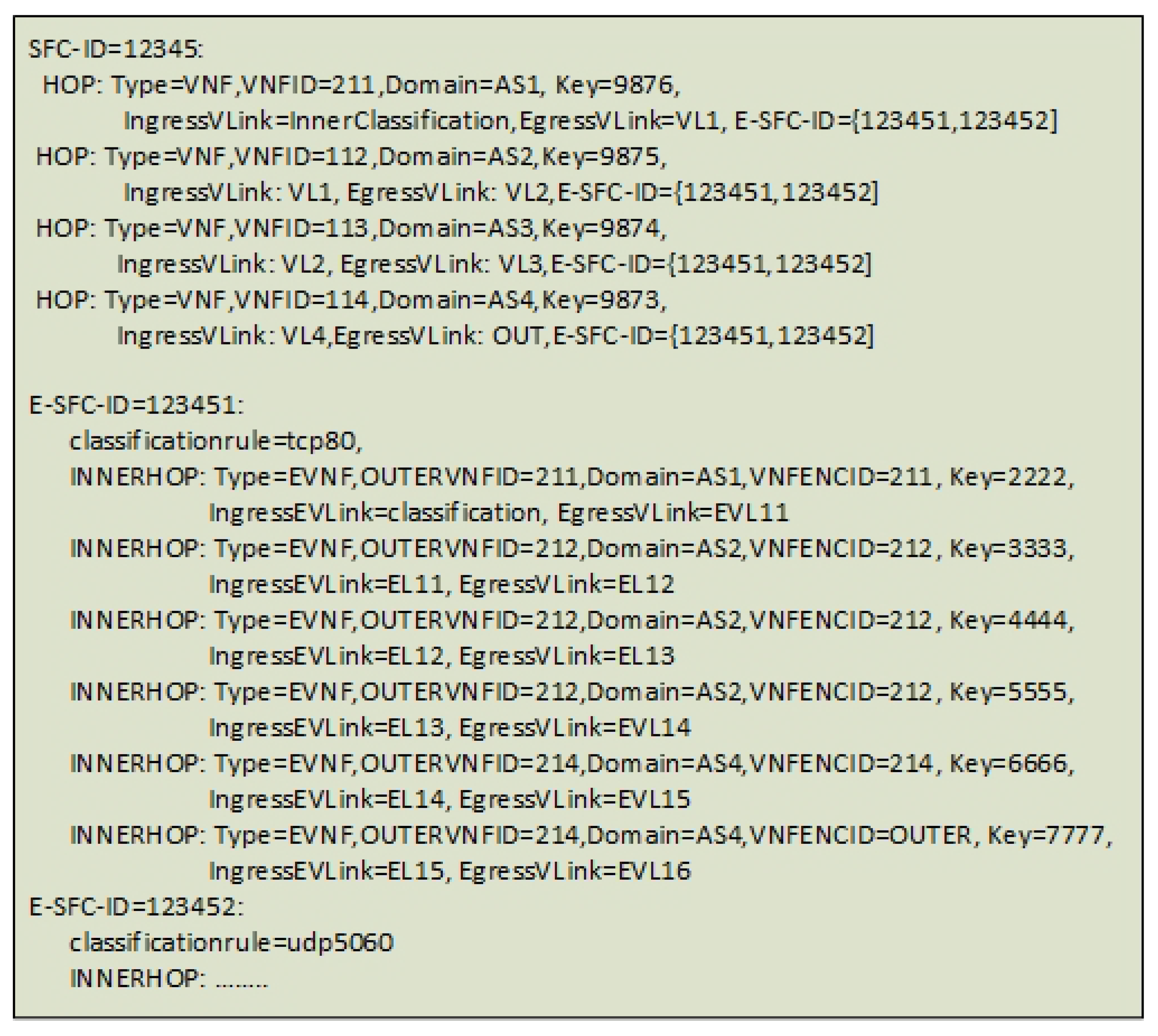
The provisioning function interface receives an NSD file that we have formed as a simplified pseudo-YAML file format supporting both the ETSI NFV and the TOSCA [22] standard. Here, the messages are compressed in a simplified proprietary manner to visualize the content of the configuration exchange. Hence, the messages do not match syntactically with the YAML format (Figure 15). The relevant information elements in the messages are:
- The Virtual Network Function Descriptor (VNFD), which in this prototype describes the instantiated Virtual Machines global identifier (VNF-ID). The VNFD also includes a description of whether the VNF is a normal VNF or an encrypting VNF (EVNF). Additionally, it includes a new Preshared Key variable (Key), which is a field that must be standardized. This is suggested to be standardized in the TOSCA VNF Configurable Property name-space [22].
- The Virtual Network Function Forwarding Graph Descriptor (VNFFGD), which describes the SFC. The format of the VNFFGD needs to include both the inner and the outer SFCs. For Proof of concept purposes, we simplify the orchestration message to one new custom file descriptor as pseudo-YAML (Figure 15).
5.1.2. Get Capabilities
This interface obtains information about the Transport Links. The response includes a list of the BGP tables for Tier 1 formatted also as NSDs.
5.1.3. Provision Transport Links
The orchestration plane receives a new SFC and calculates all Service Providers that participate in the SFC. If a Transport Link does not exist, the orchestration plane is responsible for setting up this link. If the Transport Link is set up manually, the orchestration layer informs the control plane in order to enable the BGP announcements of the Transport Link. If the link does not exist, an NSD is sent to the other orchestrator. This NSD can contain a full VPN configuration, but in the architecture the message is simplified to only contain the domain (AS number) and a Preshared Key (PSK). Furthermore, each control plane instructs the Tier 1 agent to set up the Transport Link by the use of a KMS server.
5.1.4. Provision VNFs
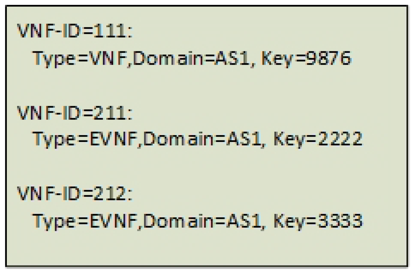
A VNF provisioning message goes between the providers’ orchestration plane. This message is also constructed as NSD, but in this paper it is simplified to a pseudo-YAML format (Figure 16). When all Service Providers have provisioned their services according to the NSD, each Compute Node will inform the related controllers about VNFs’ locations. Therefore, it is only the origin Service Provider that needs to know the SFC. The other controllers only provision the VNF. For the VNF encryption services, the Preshared Key (Key) is also attached.
5.2. Control Plane Interfaces
The services on the control plane are defined in Figure 10. This section explains the interfaces between these control plane services.
5.2.1. Control Plane Application Interfaces
The control plane application is the main application in the architecture, but, from a service interface perspective, it only has two main interfaces towards the orchestration layer. Interfaces that the control plane application implements are perceived as interfaces held by other services, explained in the following sections. The main interfaces for the control plane application are:
- An NSD interface for incoming requests from the orchestration plane. This includes the NSDs for SFC, the VNFs and the Transport Links.
- A service capability interface to get information about the Transport Links to inform the orchestration layer whether the Transport Links exist and how they are established. This service is reflected from the orchestration plane and proxies the BGP route table to the orchestration plane as an NSD.
5.2.2. Tier 1 Interfaces
The Tier 1 BGP service sends BGP messages to other network controllers, while the control agent listens for service request for Transport Link maintenance (create, delete, get, modify). Additionally, the control plane application and KMS server reads the announced BGP messages, which means that the Tier 1 agents have three interfaces.
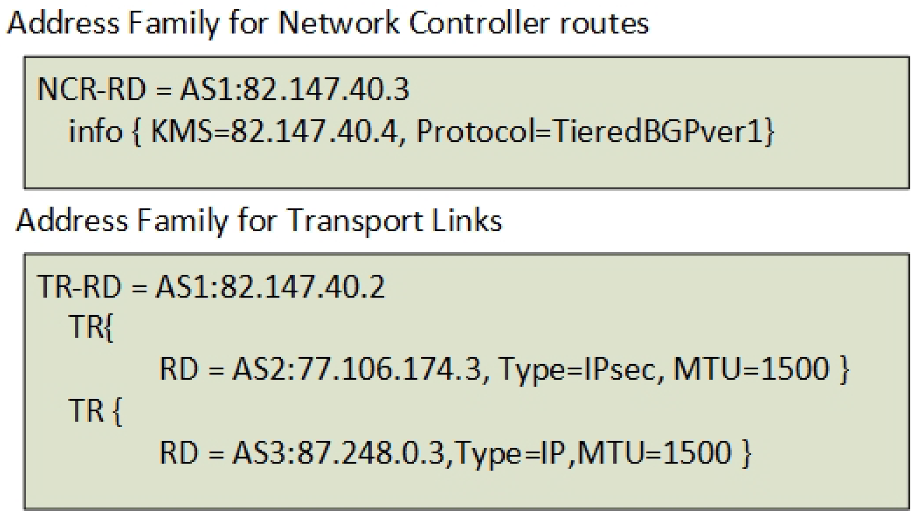
- A BGP speaker service running on the network controller. The BGP messages consist of two new address families. The new address families are reflected by the announcement of the network controllers and the announcement of the Transport Links (Figure 17). The address families are defined as Network Controller routes (NCR) and Transport Link routes (TR). These BGP messages are distributed globally.
- A configuration interface to inject new Tier 1 routes. The Tier 1 control agent receives a “create Transport Link” message from the controller application, and it injects a Transport Link route into BGP.
- A Get-Capability interface, which transports the BGP table to a YAML format that consists of all Transport Links.
Because of the tiered architecture of BGP announcements, the Tier 2 and the Tier 3 routes are automatically withdrawn if the Tier 1 Transport Link goes down. Hence, no further distribution of error handling messages is needed from the Tier 1 control agent.
5.2.3. Tiers 2 and 3 Interfaces
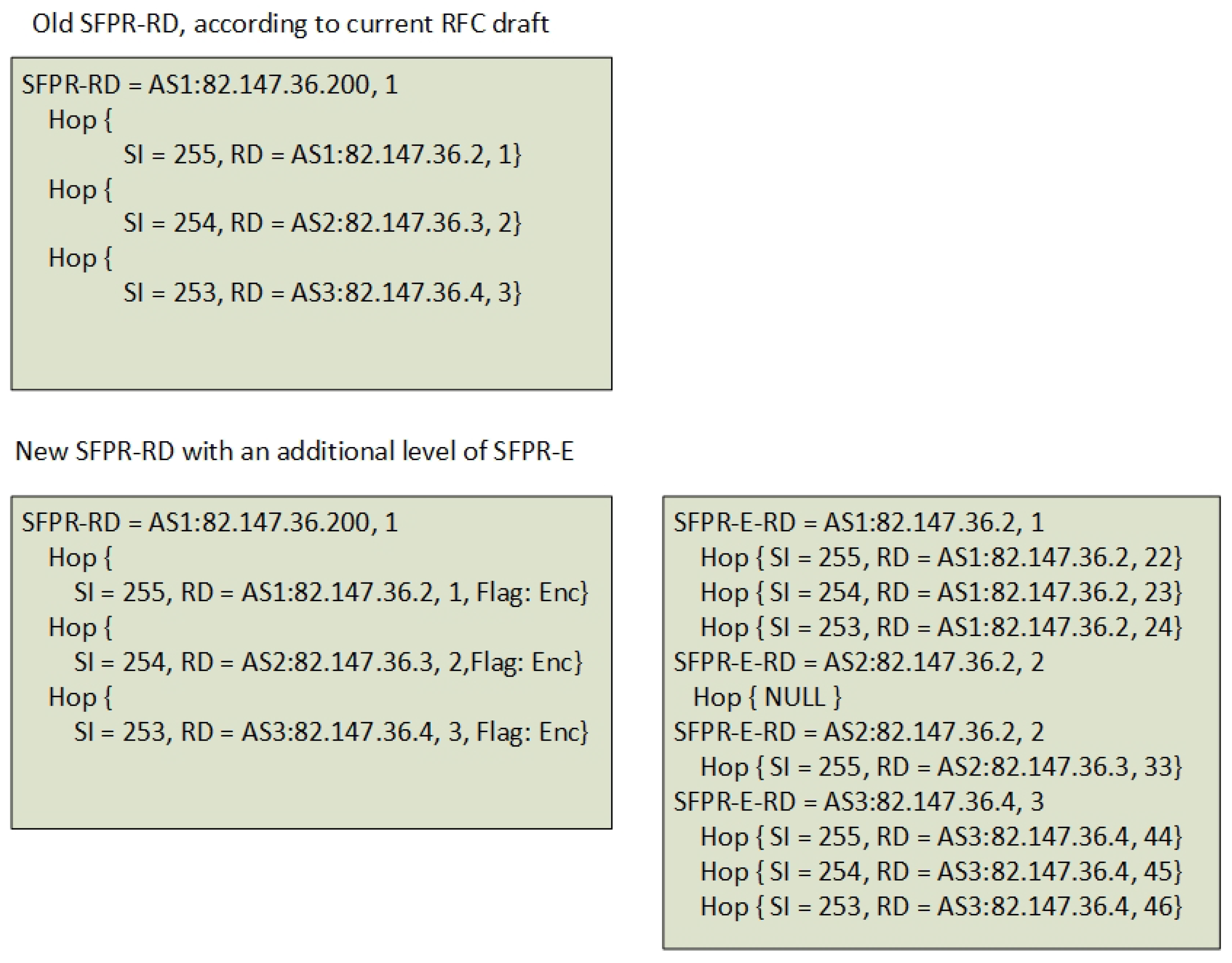
The Tier 2 and the Tier 3 control plane interfaces consist of BGP messages previously explained in Section 4.2.3. Figure 18 exemplifies how the original SFPR-RD messages [10] are changed into two new versions of SFRP-RD (Tier 2) and SFPR-E-RD (Tier 3) messages. The SFRP-RD message contains all the SFC hops in the SFC and describes the inner Encryption Links as SFPR-E-RD inner hops. Each hop consists of a Service Index (SI) that is decremented for every hop. The Route Distinguisher (RD) globally identifies the Compute Node (AS number + IP address) and also contains a Service Function Identifier (SFI) that defines the VNF instance ID (i.e., AS1:82.147.36.200,3). This RD is also the global VNF identifier used for authentication (see Section 4.2.4).
The setup of the Tier 2 and the Tier 3 peering between network controllers and Compute Nodes are considered domain specific and assumed as manually provisioned. Tiers 2 and 3 control agents on the Compute Node contain a domain specific application interface that enables the attachment and detachment of a VNF to the network, in order to announce the presence of a VNF on the Compute Node. The control agents on the network controller correspondingly hold an interface that listens for incoming rendered SFCs. In summary, the interfaces to the Tiers 2 and 3 services are:
- BGP speakers on Compute Nodes that announce connected VNFs (SFIR and SFIR-E).
- A BGP speaker on the network controller that announces the SFCs (SFPR-RD and SFPR-E-RD).
- Compute Node agent configuration interfaces for maintaining SFIRs and SFIR-Es.
- A Network controller agent configuration interface to maintain SFPR-RDs and SFPR-E-RDs.
- A Network controller agent interface that can transform YAML into BGP Tiers 2 and 3 routes and vice versa.
5.2.4. The VPN Gateway
The VPN gateway includes network protocol interfaces as follows:
- An IPVPN BGP peering interface peering towards one or more Service Provider neighbours.
- A VPN tunnel or a direct interface to all other Service Providers.
- A BGP peering interface towards the Tier 1 route reflector that announces the VPN links.
- A Tiers 2 and 3 BGP peering over the Transport Link.
- A configuration interface such as RESTconf or CLI to set up VPN links.
- A KMS server interface to accept VPN connections authorized by the KMS server.
5.2.5. Key Management Service Interfaces
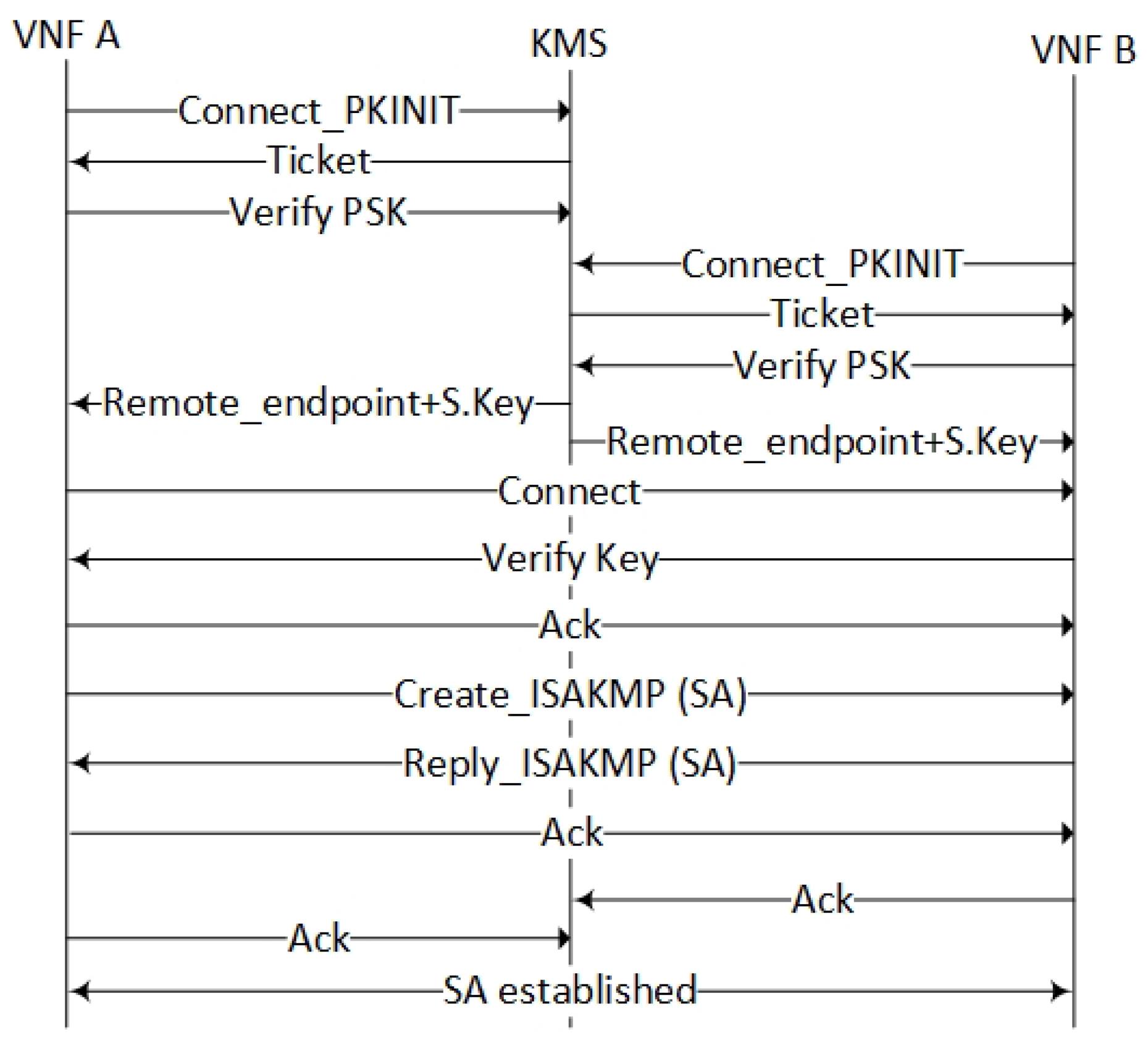
The KMS server implements a protocol that can provide an IPsec Security Association (SA) between two VNFs running encrypting services. The protocol defines a trusted KMS server with two random endpoints (instantiated encrypting VNFs) as the client and the server, where the KMS instructs the VNFs to establish an SA. For the initializing phase, the KMS server and VNFs utilize a Public Key Infrastructure (PKI) to establish a connection between each other, which the Kerberized Internet Negotiation of Keys (KINK) protocol is referring to as PKINIT [23]. Hence, certificates are issued for peers by the use of public and private keys instead of using passwords. The public keys are distributed over BGP and secured by secure origin BGP (soBGP) [24]. The KMS service provides services such as ticket granting to ensure the integrity of messages to the server. To ensure a two-way authorization, an additional Preshared Key (PSK) authentication is added (Figure 19) to the protocol. The PSK is pre-provisioned by the orchestration layer. The KMS server protocol follows the same procedure for Tiers 1–3 authentications, where the “user identity” is the only difference (see Section 4.2.4).
An additional feature to the authentication and key negotiation protocol is the capability to inform the endpoint about the IP-address of the remote endpoint. After authentication of the endpoints, the remote endpoint address together with a new dynamic shared key is offered to the endpoints by the KMS server. Next, the endpoints establish a direct link between for the SA negotiations. Furthermore, implementation guidelines about the KMS protocol are given in Section 6.
In this architecture, the KMS server is simplified to only include one instance. In real life deployment, the number of KMS instances should reflect the number of control plane tiers. In summary, the KMS server holds two service interfaces:
- An authentication protocol interface used by the encryption services and the VPN gateway,
- A management interface to maintain the “user” identities (Section 4.2.4) and their corresponding PSKs.
5.3. Data Plane Interfaces
The services on the data plane have almost no relevant communication interfaces to other service components in the architecture. This reflects the clear separation of the control plane and data plane functions. The only component that communicates with the control plane is the VNF encryption service. This functionality is explained in the KMS server interface Section 5.2.5.
6. Implementation Guidelines
The tiered packet forwarding model of SFCs is considered as the main contribution in this article. The first phase of a proof of concept implementation is therefore only applied to the SFFs on the data plane, in order to verify the packet forwarding mechanism. Hence, a full implementation of the control plane, the orchestration plane and the encryption functionalities are omitted. However, relevant implementation guidelines are given for selected components of the architecture. This section also presents a procedural example that highlights the underlined functionalities.
6.1. Data Plane Implementation
Currently, no Virtual Infrastructure platforms support SFFs with double-tagged SFC headers. For Virtual Infrastructure systems with Virtual Extensible Local Area Networks (VXLANs) such as VMWare and OpenStack, the SFFs are implemented as distributed switches (i.e., OVS or VPP [25]) connected to distributed routers, where the VNF network interface is mapped to one VXLAN identifier. These platforms are currently neither capable of SFF forwarding nor announcing SFC headers over BGP with single or double-tagged SFCs. Therefore, it is suggested to use the RFC7665 [15] adoption principles by the use of an SFC aware SFF proxy to map SFC headers to interfaces such as VXLAN. This paper does not focus on adaptation services such as SFF proxies, but, for proof of concept purposes, an SFF proxy is needed to realize an SFF implementation on the Compute Nodes. The Fast Data–Input/Output (FD.io) framework [25] is used for implementing the SFF.
The open source FD.io framework provides fast and programmable IO services for networking and storage, while it can also provide the SFF functionality that is needed. A core component of FD.io is the Vector Packet Processing (VPP) library. This library enables implementation and testing of packet forwarding. An NSH-aware middlebox can be implemented in one (or multiple) VPP nodes, which represents an implementation of an SFF. SDN frameworks such as OpenDayLight (ODL) support VPP SFFs and opens up for testing the packet forwarding in further research of SDN and NFV control plane tests. This also makes it possible to utilize existing northbound interfaces such as the wrapper application named Honeycomb for ODL.
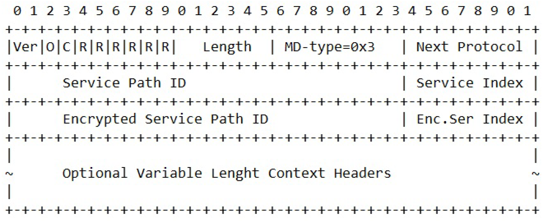
Figure 20 shows how an NSH header is formatted in order to support inner encrypted SFCs. We define a new type of NSH header named MDtype=3. This header contains both the SPI of the outer SFC and the E-SPI for the inner SFC.
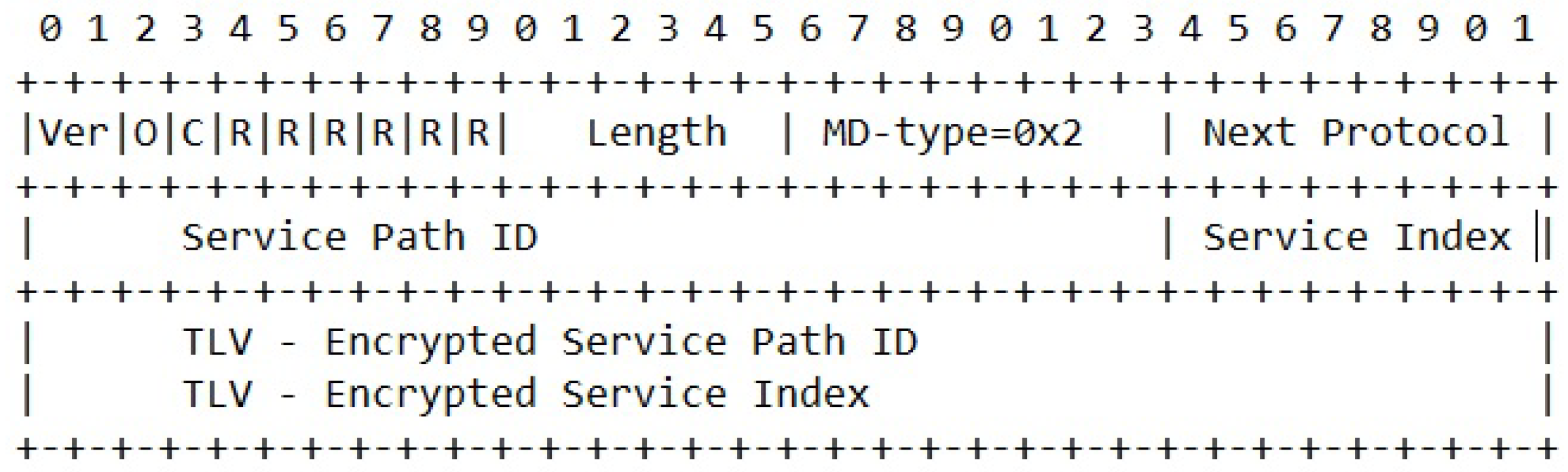
Currently, the VPP FD.io framework does not support MDtype=3. However, the current version of the NSH standard includes other extension attributes that originally was intended to be used for passing information between VNFs. For proof of concept purposes, these extension attributes are used in a proof of concept implementation. Both NSH header types named MDtype=1 and MDtype=2 support such additional attributes. Figure 21 shows how an original NSH header with MDtype=2 and type, length, value (TLV) attribute extensions can be utilized to simulate the transport of E-SPI values.
Specifying the SFF forwarding rules for NSH are configured from the FD.io command line interface or through the APIs of the honeycomb application. For proof of concept purposes, we use statically defined FD.io command lines to configure the SFF to forward NSH packets.
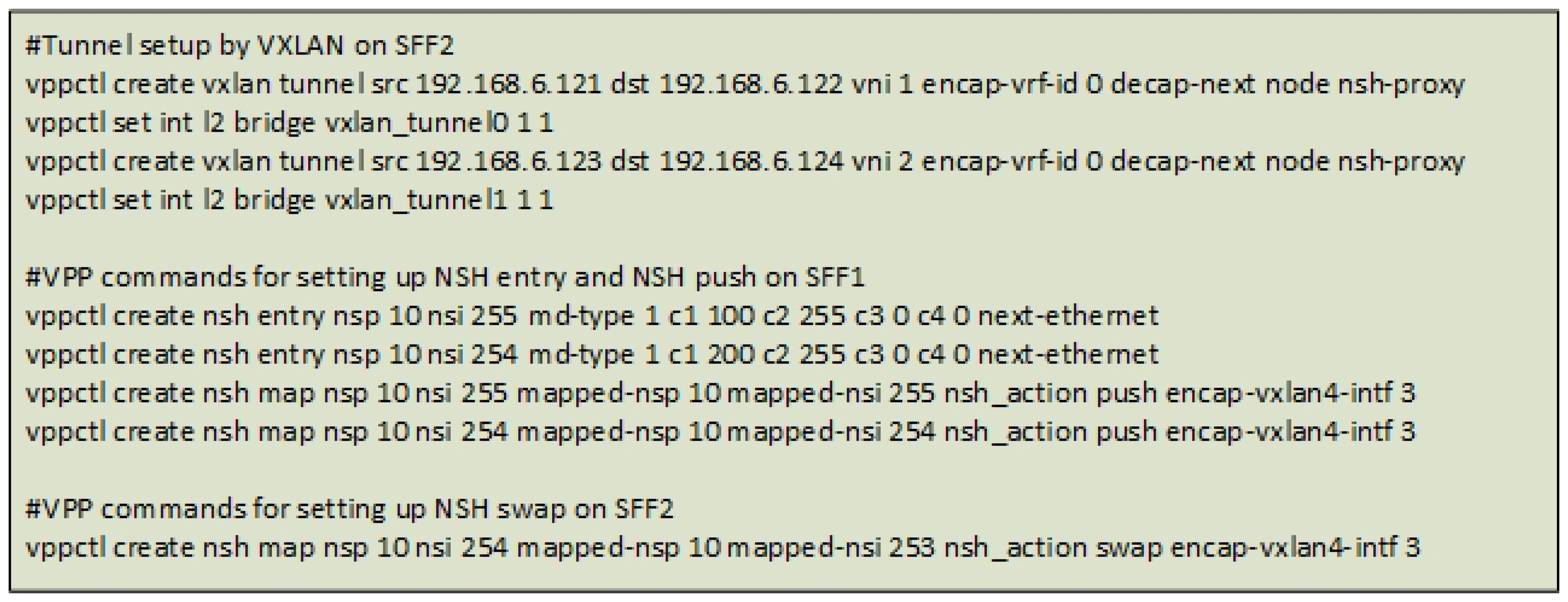
Figure 22 shows examples of the CLI commands in FD.io VPP console application that configures forwarding of NSH packets. VXLAN tunnelling simplifies the forwarding between the SFFs and is used to interconnect SFFs within a domain. The NSH entry commands define the content of the NSH headers, while the NSH map commands declare whether an NSH header is added (push), removed (pop) or modified (swap) during SFF forwarding. For MDtype=1, the NSH context headers are used to pass the inner SFC identifiers into NSH. MDtype=1 allows four context headers, where context header 1 (c1) contains the inner Service Path ID and context header 2 (c2) contains the inner Service Index. The nsp attribute in the vppctl command refers to the outer SFC identifier, while the nsi refers to the outer Service Index.
It is emphasised that this utilization of the context headers does not support a clear differentiation from the normal NSH header and that the use of context headers for transporting inner SFCs only can be used for proof of concept purposes. Furthermore, analysis of a proof of concept implementation is provided in Section 7.
6.2. BGP Services
The architecture has suggested a wide range of new BGP address families and a set of new BGP services. The Internet Assigned Numbers Authority (IANA) has to assign new Address Family Identifiers (AFI) [17] and new Subsequent Address Family Identifiers (SAFI) [17] for the new protocol to be globally supported. For proof of concept purposes, it is suggested to extend an open source BGP service, such as Quagga [26], with these address family extensions and to make a wrapper application around the service in each domain that enables extraction and injection of BGP information. This wrapper application conforms with the virtual agents in the architecture. We suggested using Honeycomb for the SFF configuration and correspondingly Honeycomb can also control the BGP services on the SFFs.
6.3. KMS Server
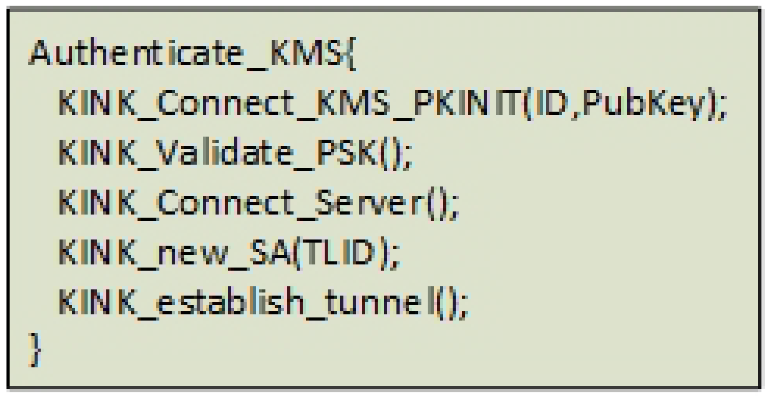
The KMS server has similarities to the KINK [23] protocol that is based on Kerberos [27], but the KINK protocol does not have the support of additional PSKs and remote server connection instructions. For proof of concept purposes, it is suggested to extend the KINK protocol in the Racoon application [28] to also include a KINK-Validate-PSK() and a KINK-connect-Server() method (Figure 23).
6.4. Control Plane Application
This section gives an example of how a tiered control plane architecture can automate the set-up of isolated and encrypted VNFs and how the control plane application can be implemented.
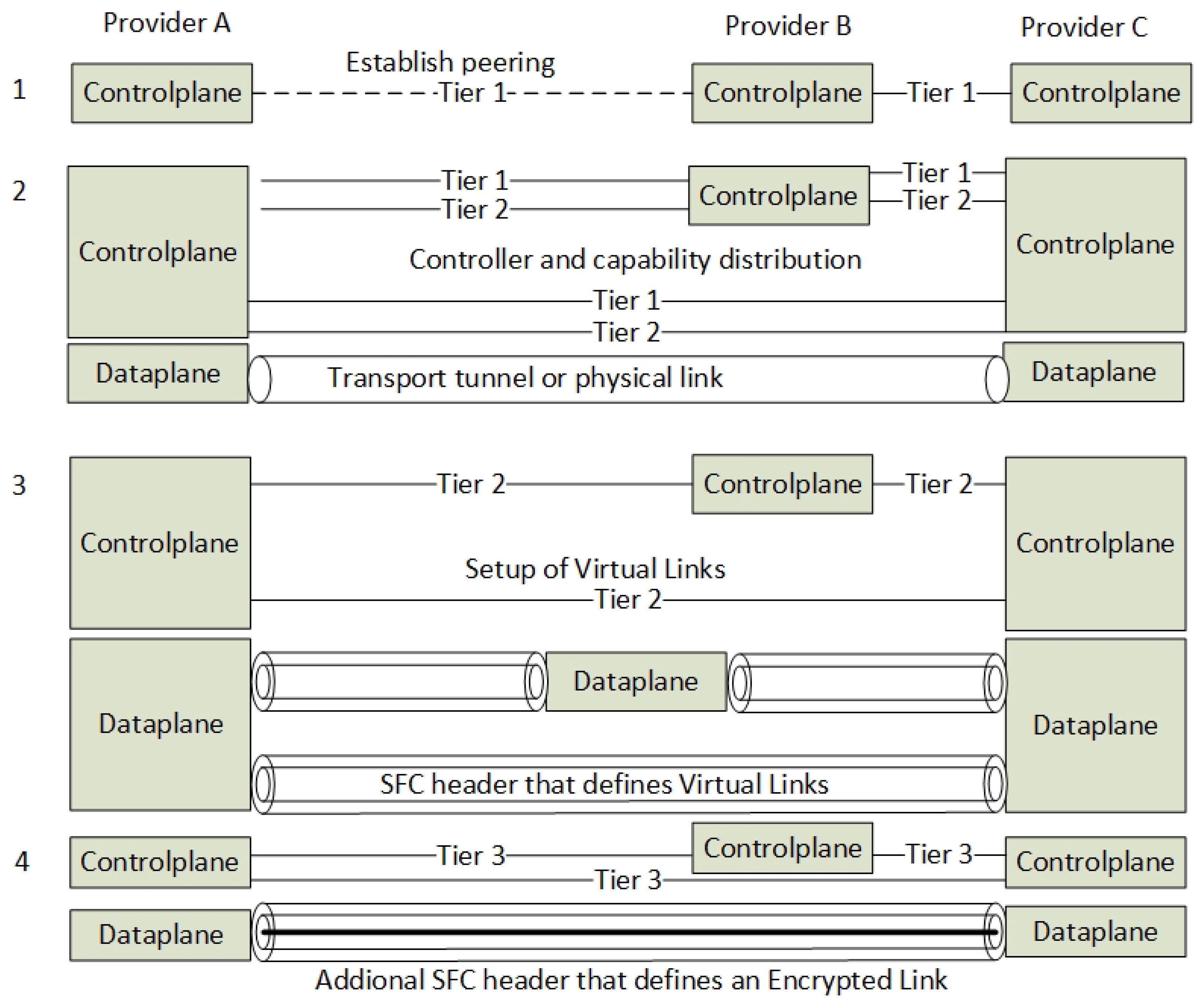
Figure 24 shows a subset of the steps in main procedure. It visualizes how a top-level contractual agreement between a set of NFV Service Providers can derive and set up subordinate control- and data-channels.
Procedure example:
Step A—A new link is established between Provider A and Provider B. A contractual peering is established on the orchestration layer and a BGP peering is made on the control plane (Figure 24(1)).
Step B—The network controllers share their connection properties as Tier 1 attributes sent over BGP.
Step C—An end-user orders a set of VNFs included in an SFC. The orchestrator instantiates the VNFs at the involved Service Providers by sending the NSDs for the VNFs and the Transport Link. If the “Get-Capability” service does not resolve a Transport Link, the Transport Link setup is processed first.
Step D—The network controller application updates the repository with a new Transport Link and inserts a new row into the identity database for Transport Links for both network controllers. Additional information such as public keys are extracted from BGP and also posted to the identity database.
Step E—The network controller applications send configuration messages to their VPN gateways as RESTconf or CLI. The configuration includes both the VPN configuration and the Tier 2 BGP peering parameters.
Step F—When the VPN tunnel is up, the control plane application requests the Tier 1 control agent to inject a Tier 1 Transport Link route. At this point, all network controllers know about all the Transport Links, and a full mesh of BGP peerings is up (Figure 24(2)).
Step G—The network orchestrator verifies that all the Transport Links are up and that all controllers run the same protocol. It sends the NSDs about the VNFs to every orchestrator that consecutively instantiates the VNFs and sends the VNF IDs to the network control plane. It must be noted that the SFC NSD is sent to the origin network controller only.
Step H—The network controller parses the SFC and stores the instantiated path in the Rendered SFC repository. For every link that needs encryption services, it stores an encryption identifier in the KMS identity database. This includes the Tier 3 SFIR identities only (according to Figure 12).
Step I—The network controller now waits for the VNFs to be provisioned by periodically read the BGP Tiers 2 and 3 route tables.
Step J—The Compute Node updates its BGP agent with the VNF ID that further injects SFIR and SFIR-E routes into BGP during VNF provisioning.
Step K—For every VNF that becomes ready, the network controller reads the SFIR and SFIR-E routes and updates the KMS with additional identity information. It also updates the Rendered SFC repository about the physical location of the VNFs.
Step L—The encryption VNFs connect to the KMS server and establish the SAs according to the KMS protocol.
Step M— When the origin network controller has noticed that all the VNFs are announced and that the KMS server has registered all encrypted links, it calculates the SFC. The SFC is sent to the Tier 1 and the Tier 2 control agents in the network controller. They convert the SFC into SFPR-RD and SRPR-E-RD BGP messages and inject them into BGP. These messages are distributed to every Compute Node and instruct them on how to route the SFC packets. These messages contain the SFC header identities that constitute the Virtual Links and the Encryption Links (Figure 24(3,4))
Step N— For an incoming packet to the Compute Node, the SFFs can now look it up in the BGP route table and calculate the next hop for both inner and outer SFCs headers.
7. Evaluation and Discussion
This section presents a proof of concept demonstration of packet forwarding with NSH headers. We also present an architectural analysis related to the proof of concept demonstration, the scalability and the limitations of the architecture.
7.1. Proof of Concept Demonstration of Data Plane Forwarding
The proposed architecture emphasises the need for encryption automation and suggests a tunnel hierarchy-model in order to overcome the SFC security problem. A full-scale implementation requires a modification of a set of NFV components, BGP network protocol extensions and it requires a development of a new protocol for key exchange between VNFs. However, a simulation of the data plane forwarding is tested in order to show the feasibility of the architecture. We state that a proof of concept demonstration on the data plane is the most important evidence that is needed before further implementations of control plane components are executed.
The test was performed on a simple VMWare ESXi 5.1 host (In a testbed provided by Eidsiva broadband, Olso, Norway based on Hewlett Packard DL380G7). Seven Virtual Machines (VMs) were created to simulate NSH packet forwarding. Four of them were running as SFFs with the VPP FD.io virtual switch software and three VMs were set up as simple end-nodes sending and receiving ICMP packets. All VMs ran Ubuntu 16.04 with the network interfaces connected to one single virtual switch. The VPP FD.io software version v18.04-rc2 was installed on every VM acting as an SFF with the NSH plugin enabled. All of the VMs were set up with /30 interface addresses with additional VXLAN tunnels defining the links between the SFFs.
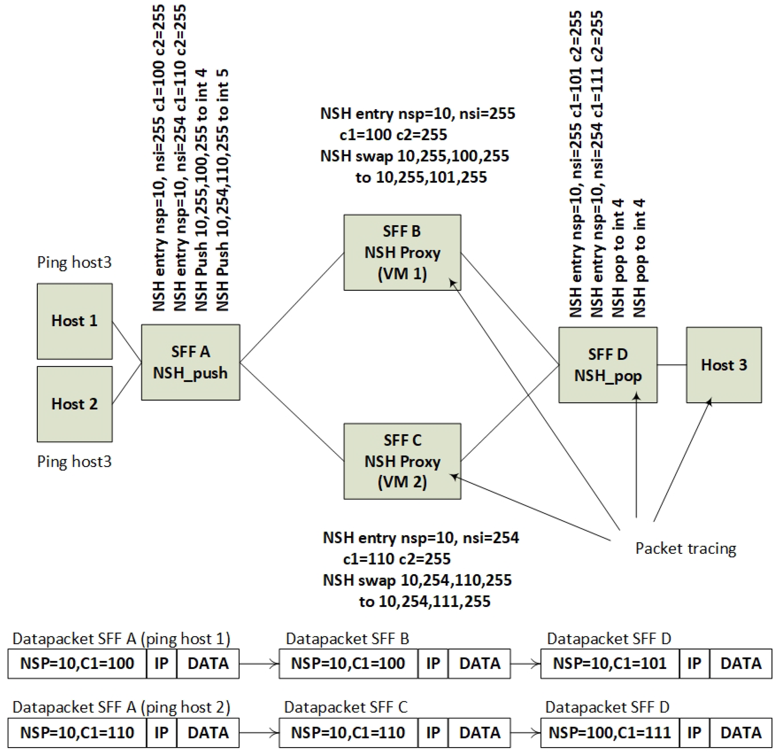
Figure 25 shows the lab topology. The lab is simplified in order to show that NSH headers with extended information about inner SFCs can be forwarded similar to normal SFC headers. The difference from a regular SFF configurations is that this new SFF configuration can split one outer SFC identifier into two SFC paths based on the inner SFC identifier. Figure 25 shows that SFF A is classifying incoming traffic from hosts 1 and 2 into one common outer SFC and two different inner SFCs. SFF A is further splitting the SFC traffic into SFF B and SFF C. SFF B and SFF C are acting as NSH proxies that simulate the role of encrypting VNFs. The NSH proxy does in this setup swap the inner SFC IDs, while it maintains the outer SFC IDs.
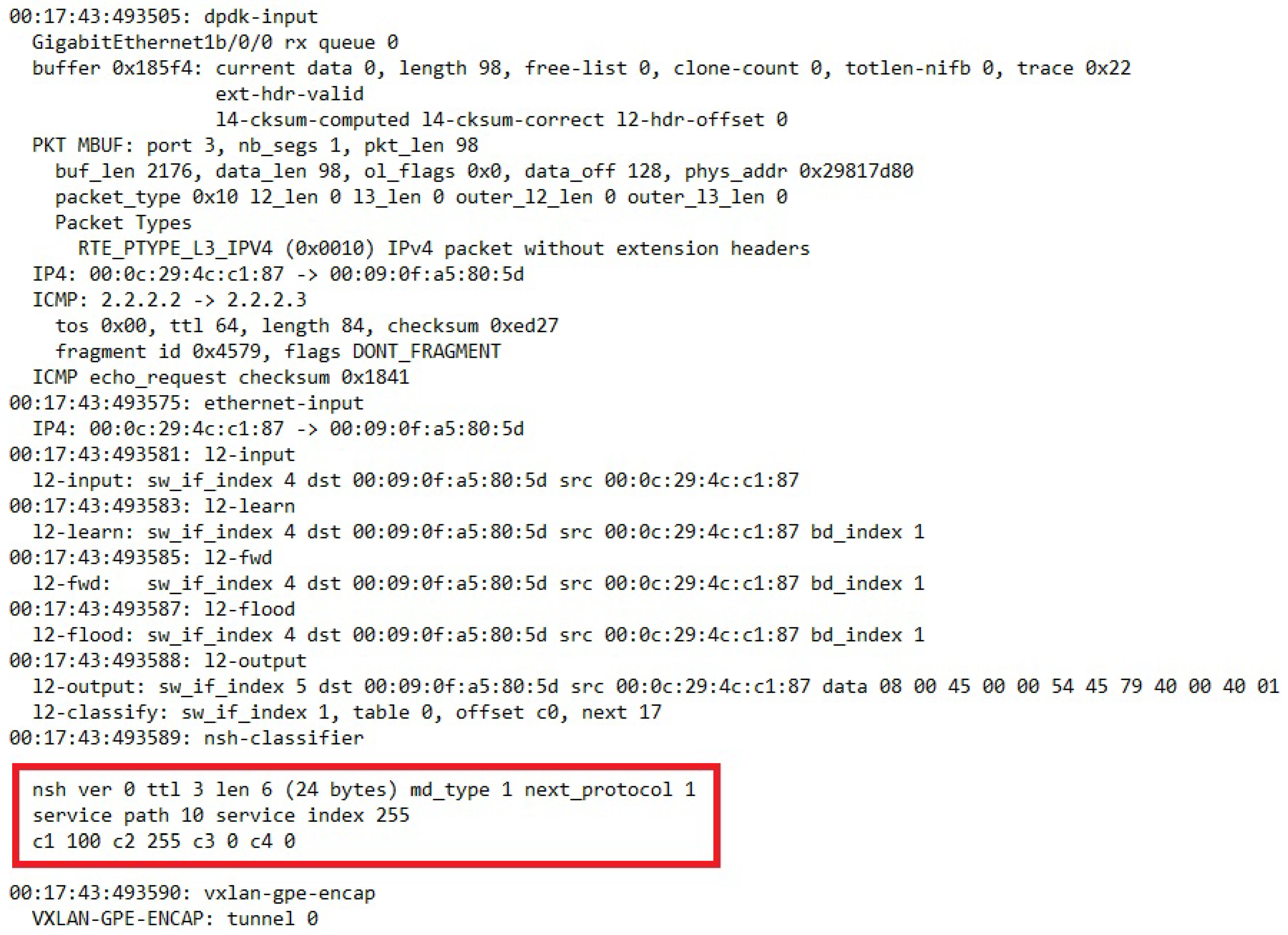
Traffic observation by using the FD.io VPP packet capture and debug feature on every SFF verified that the NSH headers were classified and modified according to the topology (Figure 26).
It must be emphasised that this proof of concept demonstration is implemented with the current NSH standard. We have utilized the existing context header attributes of NSH to be used in a new context that can conflict with other use cases of NSH context headers. We have also utilized the outer NSH SPI and NSH SI attributes to define the classification of incoming NSH packets for both inner and outer SFCs. This is because classification based on context headers is not supported in VPP v18.04-rc2. Despite these adaptations, the demonstration shows that forwarding of NSH packets with a pair of SFC identifiers is feasible. However, one demonstration with statically defined configurations of NSH packet forwarding does not prove compatibility for all SFC topologies. It also does not verify how other SFC technologies such as MPLS forwarding comply with the architecture.
The required SFF forwarding functionality presented in Section 4.3 showed that the SFFs must be able to do forwarding based two sets of SFCs and additionally maintain the SFC header information along the packet path. A subset of this topology was implemented to show this core functionality of the SFFs. We simulated that SFF B and SFF C were connected E-VNFs, while SFF A and D only forward SFCs. The core functionality is performed by SFF A that is splitting the SFF traffic into two inner paths for encryption. The packet capture verified that this splitting of one outer SFC is possible while maintaining the outer SFC identifier.
The demonstration also shows that the SFC headers can be maintained along the SFC paths. It is assumed that if the inner and the outer SFC header were two different network protocol layers, the outer SFC header would have been lost during packet processing. However, our implementation of the NSH header contains both an inner and an outer SFC in one NSH network layer. This means that outer and the inner SFC headers do not need to be separated when the packet processing parses the different network layers. The proof of concept demonstration verifies that the information in the SFC headers is maintained during packet processing.
7.1.1. Discussion of Architectural Challenges
This section discusses a subset of the most important challenges that relate to the proposed architecture. The selected topics relate to the control plane and the service plane implementation challenges and discuss the constraints in the architecture.
7.1.2. Computational Overhead
The dynamic tunnel set-up and the data traffic encryption will increase the need for computational power. The massive amount of encrypted channels can both slow down the link performance and overloading data-center resources. To offload the service plane with encryption processes, a possible solution is to utilise a common encryption component to lower the resource consumption in a data-center. It is expected that a programmable data plane [29] and distributed containers [30] will be more available on enterprise switches and routers. Both of these alternatives can possibly make encryption services run more efficiently.
7.1.3. An MTU Increase
Encrypting IP packets often results in exceeding the Maximum Transfer Unit (MTU) and consequently ends up with packet segmentation. This is considered normal in many encryption set-ups. However, an introduction of another SFC layer can potentially make additional computational overhead and packet segmentation, which results in lower performance in packet forwarding. To prevent packet segmentation, it is possible to increase the MTU. However, adding the original NSH header can alone potentially trigger packet segmentation. If the NSH header length is constant, additional NSH attributes do not influence further packet segmentation.
This architecture suggests putting the SFC header between the OSI layer 2 and the layer 3. This means that it is the layer 2 or the SFC transport layer that need an MTU increase. Hence, it is the underlying Tier 1 transport that potentially can segment packets. General solutions to this problem are to introduce an MTU limitation in the setup of VNF encryption services or using Ethernet jumbo frames on the transport links.
7.1.4. Backup Tunnels and Resilience
The architecture opens up the use of backup tunnels in order to enable fast reroutes and multi-path SFCs. Making backup paths of all possible combinations of SFCs when a VNF fails creates an exponential set of extra tunnels and additional computational overhead. However, a set of bypass backup tunnels are assumed to not extensively impound computational power when they are not in use.
The size of the route tables depends on the SFC protection algorithm that is used. A simple link protection algorithm where only one VNF is allowed to fail linearly increases the SFC route table entries by the number of VNFs. A full mesh of redundancy link where many VNFs are allowed to fail increases SFC routes exponentially by the number of VNFs. Hence, link protection of SFC routes and SFC multi-pathing is suggested to be handled by the control plane. This is because a lower number of routes makes the control plane capable of scaling and to have low failover times. A full SFC protection is suggested to be handled by the orchestration plane by using re-instantiation of VNFs and redistribution of routes. This is a slow procedure, but it makes the solution scale better when all the possibilities of failures do not need any pre-calculation.
7.1.5. Encryption Key and Backup Keys Overhead
In comparison to a regular end-to-end encryption channel that consists of a shared key or a pair of keys, this architecture suggests using multiple encryption hops with multiple pairs of keys. The keys are primarily associated with the Virtual Link, where the KMS server holds the table of keys that is ready for use. Hence, the number of keys in use is directly connected to the number of Virtual Links, where each E-VNF that are defining the Virtual Links are associated with one key each.
Rearranging the order of VNFs in the SFC does not require any alterations of the distributed keys or any E-VNFs re-instantiation. The KMS server and the E-VNF maintain their Security Association even after an E-VNF to E-VNF tunnel is torn down. However, the Security Association between the VNFs must be re-negotiated when the order of the VNFs is changed. Since the KMS server controls multiple E-VNFs, it dynamically instructs the E-VNFs about where to connect.
The main key association is between the KMS server and the E-VNFs. The SA between the E-VNFs is dynamically created by the KMS server. Hence, the KMS server creates SA records in its database that correspond to the number of link protection channels (Section 7.1.4). These database records create additional overhead, but it is not considered as a scalability problem. For example, an SFC that consists of four VNFs creates three additional link protection channels that result in three additional database records of SAs. Such additional database records are considered non-significant with respect to performance.
In addition to rearranging the order of the SFC, backup VNFs can also exist as redundant instantiations of the VNFs. From a control plane perspective, the behaviour of the KMS server is not changed, but it does consume more computational power. Typically, a pool of instantiated VNFs is instantiated together with a pool of E-VNFs. Both of these types of VNFs are registered at the KMS server where the control application makes a decision about how to connect the types of VNFs together. Hence, this overhead of additional certificates and authentication keys will have impact on the system, but it is not known how critical is for the the overall performance. Applying encryption in general clearly increase the need for computational resources (Section 7.1.2. However, per SFC encryption automation has no scientific alternative and it is difficult to compare the performance to other solutions. In addition, a measurement requires a full-scale implementation of the system that our simulation study does not provide.
The Tier 1 encryption key is a one-time instantiation between the Service Providers are is not considered as key overhead. The Tier 2 encryption keys are only suggested to be used if no isolation is needed, and is expected to give an equal overhead impact to Tier 3 E-VPN.
7.1.6. The Dynamic Behaviour of VNFs
The architecture restricts the VNFs from altering the SFC headers in order to let the VNFs themselves decide the next hop in the SFC. In order to enable such functionality together with Encrypted Links, the E-VNFs must be pre-provisioned for every alternative route. Additionally, the VNFs must have access to information about what header attributes are available for modification, such as the next SFC hop. This enforcement of encryption is considered as a security feature since it restricts the VNFs from sending traffic to random VNFs. Corrupt VNFs can possibly both inject malicious traffic into other VNFs or make Denial of Service attacks towards other users. However, when a set of predetermined SFC paths is set, it gives the VNF a choice of multiple next-hops that network administrators and the network controllers have considered as secure paths. This also allows for multi-tenancy VNFs, where a predetermined set of multiple users can share one single VNF. This functionality is not focused on in our work, but the architecture is considered to be easily adaptable for such scenarios.
7.1.7. Legacy Infrastructure
This architecture suggests a wide set of new protocol extensions to enable SFC isolation and automation. This requires that all involved Service Providers adapt to this protocol. However, the automation protocols are extensions of existing protocols, which allows the potential for old and new protocols to coexist. For example, the next header field in the NSH Base header must be set to a new type of NSH header in order to allow E-VNFs. In the proof of concept demonstration of the packet forwarding, this is set to 0 × 03. This capability of the SFF forwarding is announced by BGP Tier 1, but this Tier 1 capability information can also be exchanged manually. Hence, it is assumed that this architecture can coexist with legacy NSH infrastructures as long as the capabilities are announced over BGP.
With respect to non NSH networks, the Tier 1 transport tunnels ensure that underlying infrastructure between NFV service providers is transparent. An overlay network ensures that the network equipment not supporting NSH is bypassed by tunnels.
From a hypervisor perspective, the NFV infrastructure must support hypervisors that support the forwarding of NSH based E-VNF traffic. We believe that this research can contribute to a standardization of both a new NSH header extension and the corresponding BGP address families.
8. Future Work
For future work, we will proceed by testing the capabilities of the architecture. We have selected three areas of focus in order to make a full-scale verification of the architecture: the BGP control plane, the encryption services and the KMS key distribution protocol.
A tiered control plane with BGP can potentially raise the BGP convergence time, but since the BGP processes for Tiers 2 and 3 run in parallel, it is not known if the additional layer of SFC will significantly decrease the computational power on the control plane. In addition, it is not known how a full mesh of Transport Links will scale when the number of SFC routes and the number of interconnected NFV providers increase. Answering these questions will require a more extended test-case based validation of the proposed solutions, which is among our immediate plans.
Furthermore, the architecture suggests using VNFs on the data plane to enable encryption services. To reduce computational consumption, it is possible to run one shared encryption application instead of multiple encryption VNF applications such as flow-based IPsec. To enable flow-based IPsec to work, the IPsec application must be capable of encrypting an IP packet without stripping or encrypting the SFC header. On the contrary, this SFC header introduces additional overhead that should be compared with the overhead of multiple encryption applications versus one application.
Another aspect on which we intend to focus for our future work relates to the KMS server, which is suggested to be implemented as an extended version of the KINK protocol. The KINK protocol is limited to only support IKEv1 and has limited support of future encryption algorithms. It is suggested to investigate protocol alternatives for key exchange between two random endpoints (VNFs) with a trusted third party KMS server.
9. Conclusions
In this paper, we presented an NFV architecture for SFC isolation and encryption in inter-domain NFV topologies. The architecture suggests using a tiered control plane protocol to distribute the SFC routing information as a control plane protocol standard between NFV domains. This is accomplished by using three tiers of BGP that both scale the route distribution and enable network redundancy. The tiers are reflected as Transport Links and two layers of SFC headers. The layered network model enables the possibility of encrypting and isolating the traffic in an SFC and ensures that encryption services must be co-located with the VNF. Furthermore, the use of a KMS server is suggested, in order to automate the setup of the tunnels between the encryption services. The architecture has been presented in four abstraction layers for completeness, namely: (i) Model; (ii) Service; (iii) Protocol and Interface; and (iv) Implementation. The main contribution of this article is the introduction of a new NSH extension header that enables such an architecture. A simplified proof of concept demonstration verified that extended NSH headers can be classified and forwarded in order to support an architecture that can isolate and encrypt SFCs. Our immediate future plans are focusing on the implementation details for the control plane components in the architecture. This includes a full-scale test-case based validation and verification of the proposed architecture.
Author Contributions
The main author of this paper is H.G.; V.G. and T.K. have contributed with respect to the paper structure, quality assurance and editing.
Funding
This research was funded by Eidsiva, the Norwegian Research Council and the Norwegian University of Science and Technology (NTNU).
Conflicts of Interest
The authors declare no conflict of interest.
References
- Quinn, P.; Elzur, U. Network Service Header; Internet-Draft Draft-IETF-SFC-NSH-13; Work in Progress; Internet Engineering Task Force: Fremont, CA, USA, 2017. [Google Scholar]
- Farrel, A.; Bryant, S.; Drake, J. An MPLS-Based Forwarding Plane for Service Function Chaining; Internet-Draft Draft-Farrel-MPLS-SFC-05; Work in Progress; Internet Engineering Task Force: Fremont, CA, USA, 2018. [Google Scholar]
- Gunleifsen, H.; Kemmerich, T.; Petrovic, S. An End-to-End Security Model of Inter-Domain Communication in Network Function Virtualization; Norsk Informasjonssikkerhetskonferanse (NISK): Bergen, Norway, 2016; pp. 7–18. [Google Scholar]
- Muñoz, R.; Vilalta, R.; Casellas, R.; Martinez, R.; Szyrkowiec, T.; Autenrieth, A.; López, V.; López, D. Integrated SDN/NFV management and orchestration architecture for dynamic deployment of virtual SDN control instances for virtual tenant networks. J. Opt. Commun. Netw. 2015, 7, B62–B70. [Google Scholar] [CrossRef]
- Chowdhury, N.M.K.; Rahman, M.R.; Boutaba, R. Virtual network embedding with coordinated node and link mapping. In Proceedings of the 2009 Conference on Computer Communications, Rio de Janeiro, Brazil, 19–25 April 2009; pp. 783–791. [Google Scholar]
- Yin, H.; Xie, H.; Tsou, T.; Lopez, D.R.; Aranda, P.A.; Sidi, R. SDNi: A Message Exchange Protocol for Software Defined Networks (SDNS) across Multiple Domains; Internet-Draft Draft-Yin-SDN-SDNI-00; Work in Progress; Internet Engineering Task Force: Fremont, CA, USA, 2012. [Google Scholar]
- Haleplidis, E.; Joachimpillai, D.; Salim, J.H.; Lopez, D.; Martin, J.; Pentikousis, K.; Denazis, S.; Koufopavlou, O. ForCES applicability to SDN-enhanced NFV. In Proceedings of the 2014 Third European Workshop on Software Defined Networks (EWSDN), Budapest, Hungary, 1–3 September 2014; pp. 43–48. [Google Scholar]
- European Telecommunications Standards Institute (ETSI). Network Function Virtualization (NFV). Report on SDN Usage in NFV Architectural Framework. 2015. Available online: http://www.etsi.org/deliver/etsi_gs/NFV-EVE/001_099/005/01.01.01_60/gs_NFV-EVE005v010101p.pdf (accessed on 3 June 2018).
- Kulkarni, S.; Arumaithurai, M.; Ramakrishnan, K.; Fu, X. Neo-NSH: Towards scalable and efficient dynamic service function chaining of elastic network functions. In Proceedings of the 2017 20th Conference on Innovations in Clouds, Internet and Networks (ICIN), Paris, France, 7–9 March 2017; pp. 308–312. [Google Scholar]
- Farrel, A.; Drake, J.; Rosen, E.C.; Uttaro, J.; Jalil, L. BGP Control Plane for NSH SFC; Internet-Draft Draft-Mackie-Bess-NSH-BGP-Control-Plane-04; Work in Progress; Internet Engineering Task Force: Fremont, CA, USA, 2017. [Google Scholar]
- Quinn, P.; Elzur, U.; Pignataro, C. Network Service Header (NSH)-[Review]. 2018. Available online: https://www.rfc-editor.org/rfc/rfc8300.txt (accessed on 3 June 2018).
- Internet Engineering Task Force. Authenticated and Encrypted NSH Service Chains; Internet-Draft Draft-Reddy-SFC-NSH-Encrypt-00; Internet Engineering Task Force: Fremont, CA, USA, 2015. [Google Scholar]
- Lopez, R.; Lopez-Millan, G. Software-Defined Networking (SDN)-Based IPsec Flow Protection; Internet-DraFt Draft-Abad-I2NSF-SDN-IPsec-Flow-Protection-03; Internet Engineering Task Force: Fremont, CA, USA, 2017. [Google Scholar]
- Marques, P.R.; Mauch, J.; Sheth, N.; Greene, B.; Raszuk, R.; McPherson, D.R. Dissemination of Flow Specification Rules. 2009. Available online: https://www.rfc-editor.org/rfc/rfc5575.txt (accessed on 3 June 2018).[Green Version]
- Halpern, J.M.; Pignataro, C. Service Function Chaining (SFC) Architecture. 2015. Available online: https://www.rfc-editor.org/rfc/rfc7665.txt (accessed on 3 June 2018).[Green Version]
- Gunleifsen, H.; Kemmerich, T.; Petrovic, S. Security Requirements for Service Function Chaining Isolation and Encryption. In Proceedings of the 2017 IEEE 17th International Conference on Communication Technology, Chengdu, China, 27–30 October 2017; pp. 231–240. [Google Scholar]
- Chandra, R.; Rekhter, Y.; Bates, T.J.; Katz, D. Multiprotocol Extensions for BGP-4. 2007. Available online: https://www.rfc-editor.org/rfc/rfc4760.txt (accessed on 3 June 2018).[Green Version]
- Bush, R.; Austein, R. The Resource Public Key Infrastructure (RPKI) to Router Protocol, Version 1. 2017. Available online: https://www.rfc-editor.org/rfc/rfc8210.txt (accessed on 3 June 2018).[Green Version]
- European Telecommunications Standards Institute (ETSI). Network Function Virtualization (NFV). Management and Orchestration. 2014. Available online: http://www.etsi.org/deliver/etsi_gs/NFV-MAN/001_099/001/01.01.01_60/gs_nfv-man001v010101p.pdf (accessed on 3 June 2018).
- European Telecommunications Standards Institute (ETSI). Network Function Virtualization (NFV). Architectual Framework v1.1.1; 2013. Available online: http://www.etsi.org/deliver/etsi_gs/NFV/001_ 099/002/01.01.01_60/gs_NFV002v010101p.pdf (accessed on 3 June 2018).
- Bierman, A.; Bjorklund, M.; Watsen, K. RESTCONF Protocol. 2017. Available online: https://rfc-editor.org/rfc/rfc8040.txt (accessed on 3 June 2018).[Green Version]
- Organization for the Advancement of Structured Information Standards (OASIS). TOSCA Simple Profile for Network Functions Virtualization (NFV) Version 1.0, Committee Specification Draft 04 2016. Available online: http://docs.oasis-open.org/tosca/tosca-nfv/v1.0/tosca-nfv-v1.0.pdf (accessed on 3 June 2018).
- Vilhuber, J.; Kamada, K.; Sakane, S.; Thomas, M. Kerberized Internet Negotiation of Keys (KINK). 2017. Available online: https://www.rfc-editor.org/rfc/rfc4430.txt (accessed on 3 June 2018).
- Bellovin, S.; Bush, R.; Ward, D. Security Requirements for BGP Path Validation. 2014. Available online: https://www.rfc-editor.org/rfc/rfc7353.txt (accessed on 3 June 2018).[Green Version]
- The Fast Data Project. Vector Packet Processing Test Framework. 2016. Available online: https://docs.fd.io/vpp/17.04/ (accessed on 3 June 2018).
- Quagga. Quagga Routing Suite. 1999. Available online: http://www.quagga.net (accessed on 3 June 2018).
- Raeburn, K. Encryption and Checksum Specifications for Kerberos 5. 2005. Available online: https://www.rfc-editor.org/rfc/rfc3961.txt (accessed on 3 June 2018).[Green Version]
- Racoon. Racoon IPSec Key Exchange System. 2006. Available online: http://www.racoon2.wide.ad.jp (accessed on 3 June 2018).
- Perino, D.; Gallo, M.; Laufer, R.; Houidi, Z.B.; Pianese, F. A programmable data plane for heterogeneous NFV platforms. In Proceedings of the 2016 IEEE Conference on Computer Communications Workshops (INFOCOM WKSHPS), San Francisco, CA, USA, 10–14 April 2016; pp. 77–82. [Google Scholar]
- Eiras, R.S.V.; Couto, R.S.; Rubinstein, M.G. Performance evaluation of a virtualized HTTP proxy in KVM and Docker. In Proceedings of the 2016 7th International Conference on the Network of the Future (NOF), Buzios, Brazil, 16–18 November 2016; pp. 1–5. [Google Scholar]
Figure 1.
Extended east–west communication for Network Function Virtualization.

Figure 2.
The adversary model.

Figure 3.
Encryption possibilities.

Figure 4.
Flow identification problem.

Figure 5.
The architectural model.

Figure 6.
Additional Service Function Chaining layer.

Figure 7.
Multiple levels of communication channels.

Figure 8.
A full mesh of Transport Link tunnels.

Figure 9.
Services in the orchestration plane.

Figure 10.
Services on the control plane.

Figure 11.
Border Gateway Protocol announcements.

Figure 12.
Key Manangement Service identities.

Figure 13.
Overview of the encryption keys.

Figure 14.
Services on the dataplane.

Figure 15.
SFC provisioning message from the orchestration layer.

Figure 16.
A Virtual Network Function provisioning message.

Figure 17.
BGP announcements Tier 1.

Figure 18.
BGP announcement Tier 3.

Figure 19.
The KMS protocol (simplified).

Figure 20.
The Network Service Header structure.

Figure 21.
Packet structure in simulation.

Figure 22.
Examples of the NSH forwarding commands for Vector Packet Processing.

Figure 23.
The Kerberized Internet Negotiation of Keys authentication protocol extension.

Figure 24.
A visualization of the automated procedure.

Figure 25.
The lab topology.

Figure 26.
NSH packet capture.

© 2018 by the authors. Licensee MDPI, Basel, Switzerland. This article is an open access article distributed under the terms and conditions of the Creative Commons Attribution (CC BY) license (http://creativecommons.org/licenses/by/4.0/).
Share and Cite
MDPI and ACS Style
Gunleifsen, H.; Gkioulos, V.; Kemmerich, T. A Tiered Control Plane Model for Service Function Chaining Isolation. Future Internet 2018, 10, 46. https://doi.org/10.3390/fi10060046
AMA Style
Gunleifsen H, Gkioulos V, Kemmerich T. A Tiered Control Plane Model for Service Function Chaining Isolation. Future Internet. 2018; 10(6):46. https://doi.org/10.3390/fi10060046
Chicago/Turabian StyleGunleifsen, Håkon, Vasileios Gkioulos, and Thomas Kemmerich. 2018. "A Tiered Control Plane Model for Service Function Chaining Isolation" Future Internet 10, no. 6: 46. https://doi.org/10.3390/fi10060046
Note that from the first issue of 2016, this journal uses article numbers instead of page numbers. See further details here.