1. Introduction
According to previous studies [
1,
2], the production of renewable energy sources (RES) in Europe, and more specifically in Spain [
3], will increase their portion of the total energy consumption from 10.5% in 2008 to 22.7% in 2020. Because of this, it has been emphasized that if Europe wants to achieve its target to keep the global mean temperature increment below 2 °C, it has to strive for a 100% renewable electricity system by 2050 [
4].
It has been stated that the option of expanding solar as well as wind energy is viable in Spain [
5,
6,
7], as the former could rise 30% and the latter 15% with reasonable costs between 2020 and 2030. The cost of wind energy could be 7 c€·kWh
−1 with an investment cost between 860 and 920 €·kW
−1, while the cost of photovoltaic solar energy would be around 12.9 c€·kWh
−1 with an investment cost of 0.15 €·W
−1.
The present work examines photovoltaic grid-connected systems (PVGCSs), though it can be applied to other distributed generation (DG) technologies. The increase in the distributed-generation capacity means economic profits well as technical benefits [
8,
9,
10]. In the case of overloaded grids, the proper inclusion of distributed generation would improve the load of the grid and limit the possibility of supply collapses [
11,
12,
13]. The optimal location and size may serve multiple objectives such as reducing grid losses, updating the net value of production, and the knowledge of the distance to the point of collapse [
14,
15,
16,
17,
18,
19].
In Spain, PVGCSs have greatly expanded since the year 2004, owing to such regulations as the Royal Decree (RD) 436/2004 [
20] and RD 661/2007 [
21], though at present there is a lag in the number of new connections [
22]. Nevertheless, the rise in electric costs as well as the fall in the price of the peak watt in photovoltaic panels will make photovoltaic installations cost effective by 2016 [
23]. In addition, projects such as “Smart City”, implemented in Malaga (Spain) are focused on the integration of renewable resources in low- and medium-voltage (LV and MV) distribution grids [
24].
Most PVGCSs are connected to an existing distribution grid. In most cases, to connect a new installation it is required to reinforcement the existing grid or build a new one. In the present work, we propose a solution for increasing the maximum length of existing radial low-voltage feeders in order to encourage the inclusion of new users or DG installations.
The work is structured as follows:
Section 2 poses the problem with its previous hypotheses and describes the method of normalized calculation as well as the solution proposed.
Section 3 and
Section 4 present the results and their discussion, respectively, while
Section 5 offers the conclusions.
2. Problem Statement
Papaioannou and Purvins [
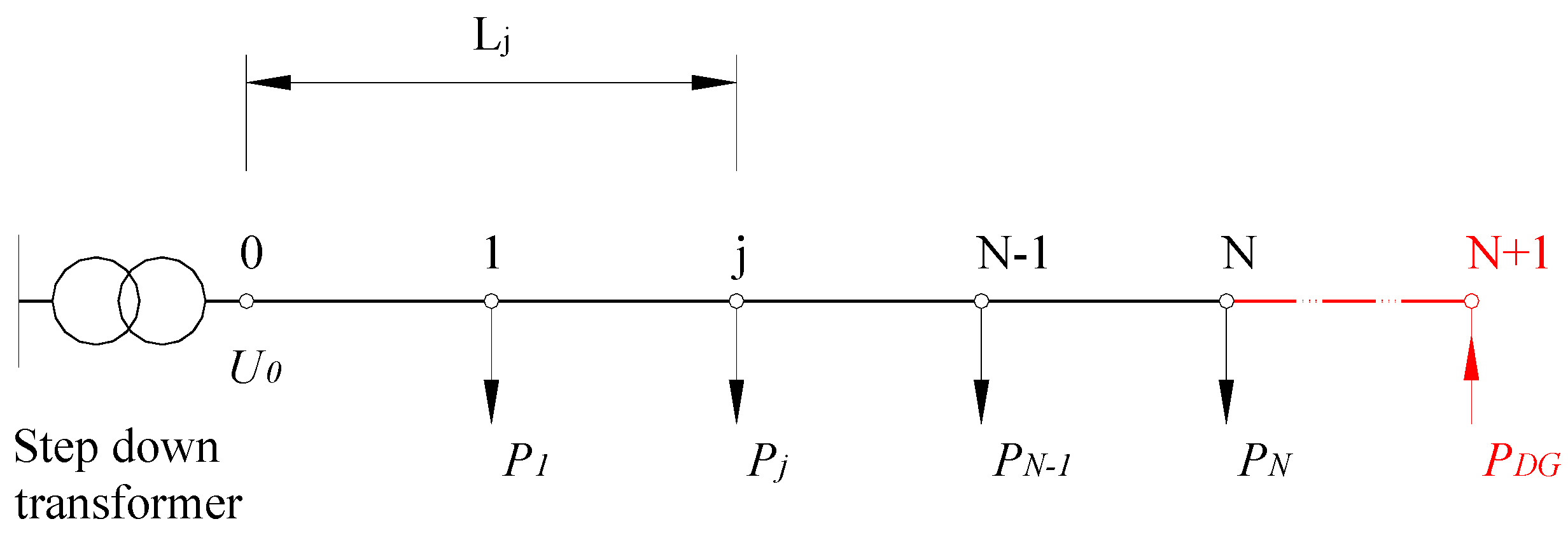
25] consider the DG generators as negative loads in radial LV feeders. In the present work, the study case is similar, but the intent is to increase the length of the distribution grid and therefore improve the connection capacity of the DG. As reflected in
Figure 1, we considered a radial grid with any configuration of connected loads, nodes 1 to N, keeping the node 0 for the feed through a step-down transformer. The problem consists of including a new node
N + 1 where connecting distributed generation and/or new users, implying a lengthening of the distribution grid of LV, according to Equation (1) and
Figure 1.
2.1. Hypotheses
The hypotheses of operation are established as follows:
Distribution grid with only one load,
i.e., N equal to 1 according to
Figure 1, for the simplicity of the grid.
The level of the previous load implies the maximum intensity reached by the overloads in the line.
The coefficients for voltage drops,
, and resistance increase by temperature in the case of a short circuit,
, are fitted to the recommendations of the electric-grid designers [
26], commonly 0.8 and 1.5, respectively.
The maximum length of the grid is limited by the lower intensity of the short circuit, i.e., the maximum length according to the condition of the voltage drop is larger than the maximum length according to the condition of the short circuit.
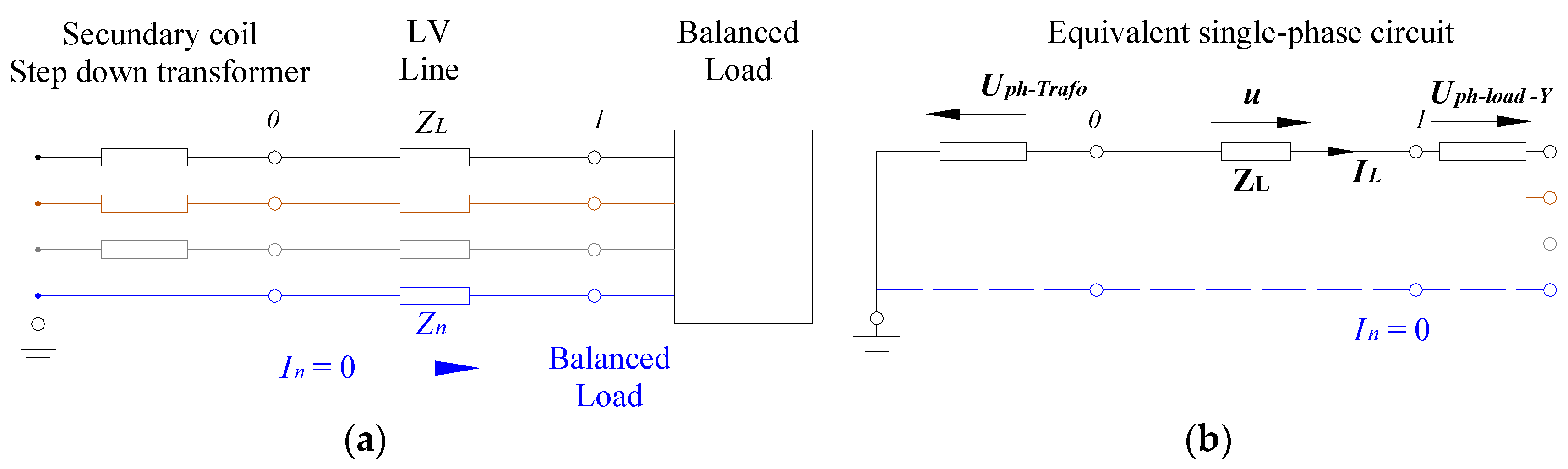
The calculations are applied to distribution grids in balanced low voltage and it is considered to be a single-phase equivalent circuit [
27].
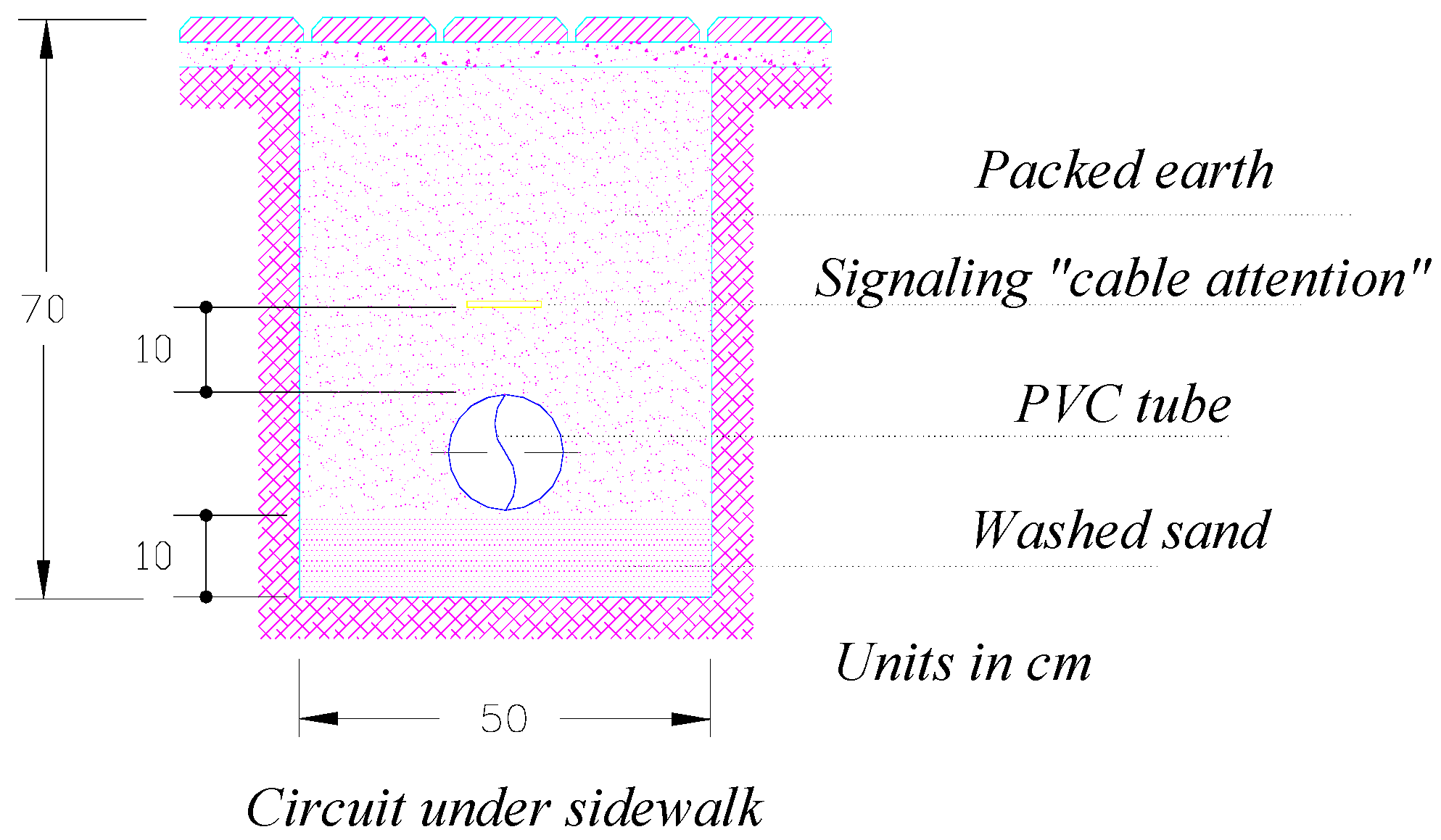
For the numerical analysis, a LV underground feeder is used according to the normative RD 842/2002 [
28] and specific rules of the distribution company [
29] (
Figure 2).
2.2. Normalized Calculation Method
Next, the design procedure for low-voltage distribution grids is described. International design guides were consulted [
30], as well as Spanish ones [
26]. For the following calculations, the single-phase equivalent circuit of the distribution grid was used (
Figure 3). The design procedure is standardized according to the International Electro-technical Committee (IEC) under Spanish regulations according to the normative [
28].
2.2.1. Calculation for Voltage Drop
The maximum voltage drop,
, recommended for a distribution grid at LV is established at 5% [
22], calculated according to Equation (2):
The length limitation established by the condition of the voltage drop,
, is determined in Equation (3):
where the conductivity,
, is determined according to
Table 1, since it is a function of temperature of the maximum permanent regime and a function of insulation (
Table 2).
2.2.2. Over Current, Calculation of Protections and Overloads
Any circuit to be protected from the effects of over currents must comply with the IEC 60364-4-43:2008/Corr.:2008 [
31]. These over currents may be originated due to: (i) overloads and (ii) short circuits.
According to the mentioned IEC 60364-4-43:2008/Corr.:2008, to guard against overloads in electrical installations, protection should be coordinated with the channeling of the circuit to be protected. To achieve this, the following conditions must be met:
where
is the intensity of the line, calculated as:
and
is the nominal intensity of the protection device. The maximum admissible intensity of the channeling,
, is that by which the conductor and therefore the insulation reaches the permanent regime temperature referred to in
Table 2 [
32].
If the environmental temperature or the installation conditions of the line are now different from that mentioned in the regulations, correction factors must be applied:
In Equation (4),
is the effective functioning intensity of the protection device. The distribution grids are protected with fuses and, therefore, the effective functioning consists of its fusion, where its value is determined by Equation (7) [
33].
2.2.3. Over Current, Calculation of Protections and Short Circuits
A short circuit is a clear defect, null-defect impedance, which causes high intensities with respect to the intensity of the permanent regime of the line, triggering spikes of dangerous temperatures for the installation. If the design of the installation is correct, a short circuit takes the wire to its maximum short-circuit temperature (
Table 3) in 5 s.
To protect an installation from short circuits, the following three conditions must be fulfilled [
26]:
- 1)
: The cut-off power,
, of the protective element should be at least equal to the short-circuit current at the beginning of the conductor where it is installed,
. Most fault currents will be symmetrical three-phase short circuits at the beginning of the installation; it is a function of the characteristics of the transformer at the beginning of the installation.
- 2)
: The minimum permanent short-circuit intensity,
, occurs at the end of the line in a phase-neutral fault, and must be greater than the fusion intensity for 5 s for the protection fuse,
[
33]. Physically, this means that it is within the time limits established for a short circuit (<5 s) and the energy-conservation equations in the adiabatic regime will be valid. The lower short-circuit current will be the one given for the fault in the phase-neutral loop:
where
The length limit,
, for an installation by the above condition is given by Equation (11):
- 3)
The thermal force admissible in the conductor,
, must be greater than the energy that the protection device allows to pass through
; where
is a constant derived from the regulations [
32] (
Table 4).
2.3. Proposed Variation to the Calculation Method
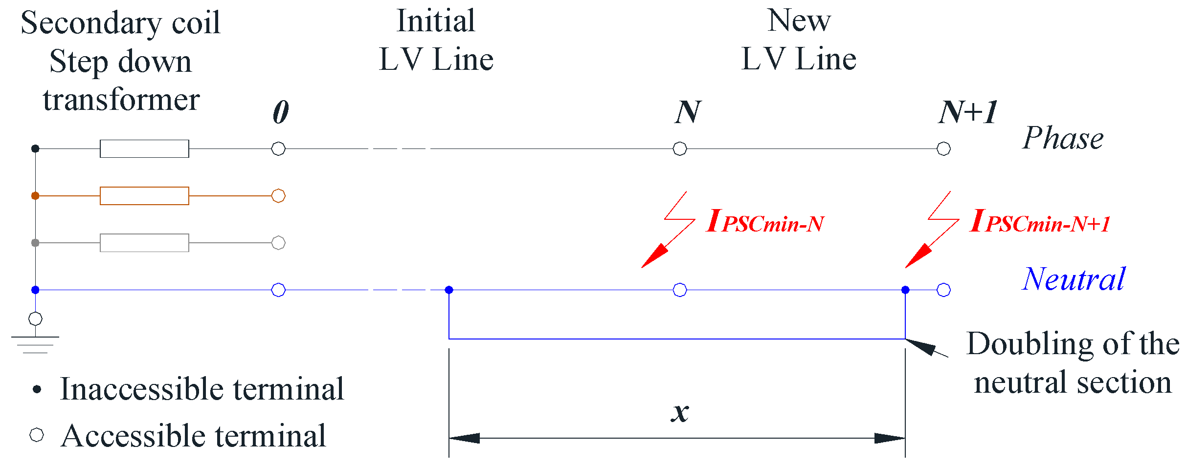
As a hypotheses, the line length is equal to the maximum length given by the condition of the short circuit, Equation (11), and smaller than the maximum length admissible from the voltage drop condition (Equation (3)). The aim is to increase the capacity of the installation in terms of the short circuits limits, thus improving the maximum length of the installation and therefore the capacity of the distribution line to connect new users and/or GD. The solution proposed in the present work is to increase the neutral section in the final segment of the distribution grid (
Figure 4). Specifically, in the case presented, the neutral conductor will be doubled, thereby duplicating the initial section.
Figure 4 shows that the distribution grid now includes N + 1 nodes and has increased its length, as
is greater than
. The impedance of any phase-neutral fault loop and thus the intensity of the corresponding short circuit depends on the length,
, which requires that the neutral conductor doubles. As established in the hypotheses, if the minimum short circuit at node N takes the minimum value (
) then, any lengthening desired of node N + 1 will be require a lengthening of the doubled neutral conductor, as reflected in Equation (12).
The minimum length of the neutral line doubling,
, must be such that on lengthening the line from
to
, the fault in any modified phase-neutral loop is greater than or equal to the initial fault without modification; where, according to the hypotheses, takes the value of
.
On the other hand, the maximum length of the neutral doubling,
, must be less than
, and the fault of any phase-neutral loop is lower than or equal to
(Equation (14)).
Finally, the maximum value that the line can increase from
to
is determined by operating in the inequality of Equation (14), giving:
3. Results
Normalized calculation was applied as was the variation proposed for an underground LV distribution grid installed in conduit, according to the regulation [
28] (
Figure 2). The conductors used are made of aluminum, with insulation strength of 0.6/1 kV, and XLPE insulation; the sections used in this case study are 150 mm
2 and 240 mm
2, according to the particular norms of the distribution company [
29].
3.1. Length Line Calculation by the Normalized Method
The study begins by calculating for overloads and it is considered that the line will be the maximum of its capacity for overloads, then, the minimum length line is calculated from the conditions of the voltage drop and short circuit.
3.1.1. Overloads
For the calculation of the maximum admissible intensity and of the corresponding correction factors, the Complementary Technical Instruction ITC-BT-07 of the regulation of low voltage RD 842/2002 is used [
28]. According to Equation (6), the diameter of the fuse fit the normative IEC 60269-1:2006 [
33]. The fuses must meet the conditions of Equation (4). For each line section, the largest fuse that fulfilled these conditions is selected (
Table 5). Thus, it fulfills the hypotheses of
Section 2 and the load can reach the maximum intensity to overloads in the line.
3.1.2. Voltage Drop Condition
According to
Table 5, the line is limited by the capacity of effective functioning of the fuse. Thus, the nominal power admitted by the line is adjusted to the nominal intensity of the fuse for each section. The nominal power for each case (Equation (16)) and the maximum length from voltage drop condition (Equation (3)) are shown in
Table 6.
3.1.3. Short-Circuit Protection
- 1)
: The maximum intensity of short circuit, symmetrical three-phase fault, is given at the beginning of the distribution grid and it depends on the power of the distribution transformer. Here, has been considered a transformer of 630 kVA, where a fault will take an intensity of value (Equation (17)):
- 2)
: As can be seen in
Table 7, this condition limits the maximum length of the distribution line (Equation (11)), as this is less than the maximum length per voltage drop (Equation (3)).
- 3)
This condition of the short circuit is fulfilled. Further details are not given, since the length of the distribution line is not affected by this condition.
3.2. Line Length Calculation with the Variation Proposed for the Grid Design
As reflected in
Table 7, the condition of minimum short circuit limits the maximum length of the distribution line under the hypotheses of
Section 2 and according to Equation (11). With the doubling of the neutral section (Equation (12)), the length of the exploitation of the distribution line can lengthen up to what is established in Equation (15) (
Table 8). This alternative design implies an increase in the line length more than 20%.
4. Discussion
The solution proposed would be applied to any installation where the maximum length reached by a voltage drop is greater than the maximum length reached by the least short circuit of the grid. Although, for greater simplicity, the calculation example was developed for a radial distribution grid with a single load, that is, with regard to
Figure 1, it corresponds to the case in which N is equal to 1; and where the load implies the 100% of the thermal load capacity of the line.
From this standpoint, the length of the short circuit is increased, with margins sufficient to undertake the implementation of new users and/or DG in the line. This configuration does not use a new output of the step-down transformer; this is considered an advantage by being their limited number.
The fact of considering the same section for the neutral conductor as for the phases is to improve the logistics and installation of the distribution grid, as only one section was used for all the poles of the three-phase grid.
5. Conclusions
This paper proposes a simple solution, adjusted to the relevant regulations and embodied in a radial distribution grid of Spanish low voltage, to improve the interconnection of distributed generation, usually grid connected photovoltaic systems.
The solution proposed, i.e., the partial doubling of the neutral section, can increase the length of the use of a low voltage distribution generation by up to 20%. This would improve the connection capacity of distribution grid installations as well as photovoltaic grid-connected systems, since in most cases these installations are installed over previously constructed distribution grids.
Author Contributions
José Agüero-Rubio has carried out most of the work presented in this paper. Javier López-Martínez, José Ignacio Rojas-Sola and Ángel Jesús Callejón-Ferre have contributed with the entire manuscript critical revision and improving the introduction, conclusions and references sections.
Conflicts of Interest
The authors declare no conflict of interest.
Abbreviations
| Coefficient of resistance |
| Coefficient of voltages |
| Voltage drop, in V |
| Correlation factor for intensity, in A |
| Fci | Correction factor for installation |
| Fct | Correction factor for temperature |
| Intensity of the circuit to protect, in A |
| Cut-off power of the protection device, in A |
| Fusion intensity for a fuse in 5 s, in A |
| Intensity of the line, in A |
| Neutral current, in A |
| Nominal intensity of the protection device, in A |
| Permanent intensity of the short circuit, in A |
| Intensity consulted from normalized tables in A |
| Maximum intensity of the normalized channeling, in A |
| Conductivity of the conductor, in Ω−1·mm−2·m |
| Total length from node 0 to node j, in m |
| PC | Calculated power, in W |
| Nominal power, in W |
| Section of a conductor, in mm2 |
| Resistance of a line, in Ω |
| Neutral resistance, in Ω |
| Resistance of a phase, in Ω |
| Unit resistance, in Ω·m−1 |
| Difference between voltage and phase intensity, in rad |
| cos | Power factor of value 0.8 in this research |
| Uph | Voltage between phase and neutral, in V |
| UL | Line voltage, in V |
| XL | Inductive impedance of the line, in Ω |
| Xn | Inductive impedance of the neutral, in Ω |
| Xph | Inductive impedance of the phase, in Ω |
| Xu | Unit inductive impedance, in Ω·m−1 |
| ZCC | Short-circuit impedance of the distribution transformer |
| ZL | Line impedance, in Ω |
| ZLOOP | Impedance of the phase-neutral loop, in Ω |
References
- European Parliament. Directive 2009/28/EC of the European Parliament and of the Council of 23 April 2009 on the promotion of the use of energy from renewable sources and amending and subsequently repealing Directives 2001/77/EC and 2003/30/EC. Off. J. Eur. Union L 2009, 140, 16–47. [Google Scholar]
- IDAEt. Institute for Energy Diversification and Saving. Renewable Energy Plan, 2011–2020. Ministry of Industry, Tourism and Trade. 2011. Available online: http://www.idae.es/index.php/id.670/relmenu.303/ mod.pags/ mem.detalle (accessed on 4 March 2016).
- Montoya, F.G.; Aguilera, M.J.; Manzano-Agugliaro, F. Renewable energy production in Spain: A review. Renew. Sustain. Energy Rev. 2014, 33, 509–531. [Google Scholar] [CrossRef]
- Battaglini, A.; Lilliestam, J.; Haas Patt, A. Development of SuperSmart Grids for a more efficient utilization of electricity from renewable sources. J. Clean. Product. 2009, 17, 911–918. [Google Scholar] [CrossRef]
- Ghassan, Z. Technolgy mix alternatives with high shares of wind power and photovoltaics-case study for Spain. Energy Policy 2011, 39, 8070–8077. [Google Scholar]
- Castellano, N.N.; Gázquez Parra, J.A.; Valls-Guirado, J.; Manzano-Agugliaro, F. Optimal displacement of photovoltaic array’s rows using a novel shading model. Appl. Energy 2015, 144, 1–9. [Google Scholar] [CrossRef]
- Fernández-García, A.; Rojas, E.; Pérez, M.; Silva, R.; Hernández-Escobedo, Q.; Manzano-Agugliaro, F. A parabolic-trough collector for cleaner industrial process heat. J. Clean. Prod. 2015, 89, 272–285. [Google Scholar] [CrossRef]
- Viral, R.; Khatod, D.K. Optimal planning of distributed generation systems in distribution system: A review. Renew. Sustain. Energy Rev. 2012, 16, 5146–5165. [Google Scholar] [CrossRef]
- Hong, Y.Y.; Lai, Y.M.; Chang, Y.R.; Lee, Y.D.; Liu, P.W. Optimizing capacities of distributed generation and energy storage in a small autonomous power system considering uncertainty in renewables. Energies 2015, 8, 2473–2492. [Google Scholar] [CrossRef]
- Agüero-Rubio, J.; Giménez-Fernández, A.; Callejón-Ferre, A.J.; López-Martínez, J. Simple rule for management of thermal loads with real-time prices. J. Clean. Prod. 2014, 78, 48–53. [Google Scholar] [CrossRef]
- Rosehart, W.; Cañizares, C.; Quintana, V. Costs of Voltage Security in Electricity Markets. In Proceedings of the IEEE/PES Summer Meeting, Seattle, WA, USA, 16–20 July 2000.
- Thomson, M.; Infield, D.G. Impact of widespread photovoltaics generation on distribution systems. IET Renew. Power Syst. 2007, 1, 33–40. [Google Scholar] [CrossRef]
- Hermoso-Orzáez, M.J.; Rojas-Sola, J.I.; Gago-Calderón, A. Electrical consequences of large-scale replacement of metal halide by LED luminaires. Light. Res. Technol. 2016. [Google Scholar] [CrossRef]
- Gianni, C.; Ghiani, E.; Mocci, S.; Pilo, F. A Multiobjetive Evolutionary Algorithm for the Sizing and Siting of Distributed Generation. IEEE Trans. Power Syst. 2005, 20, 750–757. [Google Scholar]
- Haesen, E.; Driesen, J.; Belmans, R. Robust planning methodology for integration of stochastic generators in distribution grids. IET Renew. Power Gener. 2007, 1, 25–32. [Google Scholar] [CrossRef]
- Hernández, J.C.; Mediana, A.; Jurado, F. Optimal allocation and sizing for profitability and voltage enhancement of PV systems on feeders. Renew. Energy 2007, 32, 1768–1789. [Google Scholar] [CrossRef]
- Baños, R.; Manzano-Agugliaro, F.; Montoya, F.G.; Gil, C.; Alcayde, A.; Gómez, J. Optimization methods applied to renewable and sustainable energy: A review. Renew. Sustain. Energy Rev. 2011, 15, 1753–1766. [Google Scholar] [CrossRef]
- Sánchez, P.; Montoya, F.G.; Manzano-Agugliaro, F.; Gil, C. Genetic algorithm for S-transform optimisation in the analysis and classification of electrical signal perturbations. Expert Syst. Appl. 2013, 40, 6766–6777. [Google Scholar] [CrossRef]
- Montoya, F.G.; Manzano-Agugliaro, F.; López, J.G.; Alguacil, P.S. Power quality research techniques: Advantages and disadvantages. DYNA 2012, 79, 66–74. [Google Scholar]
- Boletín Oficial del Estado (BOE). Royal Decree 436/2004, Dated 12 March 2004, Establishing the Methodology for the Updating and Systematisation of the Legal and Economic Regime of Activity of Production of Electrical Energy in Special Regime; BOE No. 75; BOE: Madrid, Spain, 27 March 2004; pp. 13217–13238. [Google Scholar]
- Boletín Oficial del Estado (BOE). Royal Decree 661/2007, Dated 25 May 2007, Regulates Spain's Energy Sector and the Production of the Nation's Electricity Supply under a Special Regime; BOE No. 126; BOE: Madrid, Spain, 26 May 2007; pp. 22846–22886. [Google Scholar]
- Del-Río, P.; Mir-Artigues, P. Support for solar PV deployment in Spain: Some policy lessons. Renew. Sustain. Energy Rev. 2012, 16, 5557–5566. [Google Scholar] [CrossRef]
- Movilla, S.; Miguel, L.J.; Blazquez, L.F. A systems dynamics approach for the photovoltaic energy market. Energy Policy 2013, 60, 142–154. [Google Scholar] [CrossRef]
- Ruiz-Romero, S.; Colmenar-Santos, A.; Mur-Pérez, F.; Lopez-Rey, A. Integration of distributed generation in the power distribution network: The need for smart grid control systems, communication and equipment for a smart city—Use cases. Renew. Sustain. Energy Rev. 2014, 38, 223–234. [Google Scholar] [CrossRef]
- Papaioannou, I.T.; Purvins, A. A methodology to calculate maximum generation capacity in low voltage feeders. Int. J. Electr. Power. Energy Syst. 2014, 57, 141–147. [Google Scholar] [CrossRef]
- Dmelect, S.L. Software for installations 2005. Theory of Low Voltage Electrical Installations. 2005. Available online: http://www.dmelect.com/ (accessed on 26 May 2016).
- Guirado-Torres, R.; Asensi-Orosa, R.; Jurado-Melguizo, F.; Carpio-Ibáñez, J. Electric Technology; McGrawHill: New York, NY, USA, 2006; ISBN 84-481-4007-X. [Google Scholar]
- Boletín Oficial del Estado (BOE). Royal Decree 842/2002, Dated 2 August 2002, Electro-technical Regulation for Low Voltage and and its Technical Specifications; BOE No. 224; BOE: Madrid, Spain, 18 September 2002; pp. 33084–33086. [Google Scholar]
- Endesa, S.A. Particular Rules and Technical and Safety Conditions Sevillana-Endesa. 2005. Available online: http://www.endesa.com/es/proveedores/normativaycondicionescontratacion/home?folder=47572da5-b001–4c2e-9f3a-3ba725ea3251 (accessed on 12 March 2016).
- Schneider Electric España S.A. Electrical Installation Guide according to International Standards IEC; MerlínGerin: Madrid, Spain, 2005; ISBN 84-609-8658-6. [Google Scholar]
- Low-Voltage Electrical Installations—Part 4–43: Protection for Safety—Protection against Overcurrent; IEC 60364-4-43:2008/Corr.:2008; Equivalent to UNE-HD 60364-4-43:2013; IEC: Geneva, Switzerland, 2008.
- Electrical Installations of Buildings—Part 5: Selection and Erection of Electrical Equipment-Section 523: Current-Carrying Capacities in Wiring Systems; IEC 60364-5-523:1999; IEC: Geneva, Switzerland, 1999.
- Low-Voltage Fuses—Part 1: General Requirements; IEC 60269-1:2006; IEC: Geneva, Switzerland, 2006.
© 2016 by the authors; licensee MDPI, Basel, Switzerland. This article is an open access article distributed under the terms and conditions of the Creative Commons Attribution (CC-BY) license (http://creativecommons.org/licenses/by/4.0/).


 and
and 


