Article

Nonhumidified Fuel Cells Using N-Ethyl-N-methyl-pyrrolidinium Fluorohydrogenate Ionic Liquid-poly(Vinylidene Fluoride-Hexafluoropropylene) Composite Membranes

by
Pisit Kiatkittikul
1,
Toshiyuki Nohira
2,* and
Rika Hagiwara
1,*
1
Department of Fundamental Energy Science, Graduate School of Energy Science, Kyoto University, Sakyo-ku, Kyoto 606-8501, Japan
2
Institute of Advanced Energy, Kyoto University, Uji, Kyoto 611-0011, Japan
*
Authors to whom correspondence should be addressed.
Energies 2015, 8(6), 6202-6214; https://doi.org/10.3390/en8066202
Submission received: 5 May 2015 / Revised: 3 June 2015 / Accepted: 16 June 2015 / Published: 23 June 2015
(This article belongs to the Special Issue Polymer Electrolyte Membrane Fuel Cells 2015)

Abstract

:
Composite membranes consisting of N-ethyl-N-methylpyrrolidinium fluoro-hydrogenate (EMPyr(FH)1.7F) ionic liquid and poly(vinylidene fluoride hexafluoro-propylene) (PVdF-HFP) copolymer were successfully prepared in weight ratios of 5:5, 6:4, and 7:3 using a casting method. The prepared membranes possessed rough surfaces, which potentially enlarged the three-phase boundary area. The EMPyr(FH)1.7F/PVdF-HFP (7:3 weight ratio) composite membrane had an ionic conductivity of 41 mS·cm−1 at 120 °C. For a single cell using this membrane, a maximum power density of 103 mW·cm−2 was observed at 50 °C under non-humidified conditions; this is the highest power output that has ever been reported for fluorohydrogenate fuel cells. However, the cell performance decreased at 80 °C, which was explained by penetration of the softened composite membrane into gas diffusion electrodes to partially plug gas channels in the gas diffusion layers; this was verified by in situ a.c. impedance analysis and cross-sectional SEM images of the membrane electrode assembly.

1. Introduction

Conventional polymer electrolyte fuel cells (PEFCs) membrane materials such as Nafion® require sufficient humidity for proton conduction; this necessitates a complicated humidification system and limits the operation temperature range to between the freezing and boiling points of water [1,2,3,4]. However, operation of PEFCs above 100 °C without humidification would enable the possible reduction of the need for expensive noble metal catalysts and simplification of the fuel cell unit. Thus, it is necessary to develop new electrolyte membranes.
In recent decades, ionic liquids (ILs), salts that are liquid at below 100 °C, have received more and more attention as potential electrolytes for applications in electrochemical devices because of their high chemical and thermal stability, nonflammability, nonvolatile nature, and wide electrochemical window [5,6,7]. Among the various types of ILs, our group has particularly focused on fluorohydrogenate ILs (FHILs), which consist of organic cations and fluorohydrogenate anions, (FH)nF, where n represents the average number of HF ligands attached to the fluoride anion. This n number decreases when the evacuation temperature increases, which means more HF is removed from FHILs to be stabilized at higher temperature. The general chemical structure of fluorohydrogenate anions is presented in Figure 1a. We have continually developed and studied a variety of FHILs [8,9,10,11,12,13,14,15,16,17,18]; for example, 1-ethyl-3-methylimidazolium fluorohydrogenate (EMIm(FH)2.3F), which was the first reported FHIL, exhibits high conductivity (100 mS·cm−1 at 25 °C) and has a low melting point (−65 °C) and low glass transition temperature (−125 °C) [8,12], making it a promising electrolyte for electrochemical devices.
Figure 1. General chemical structures of (a) fluorohydrogenate anions and (b) PVdF-HFP.
Energies 08 06202 g001
For fuel cell applications, we have already proposed operation mechanisms for nonhumidified fuel cells using FHILs as electrolytes; these cells are referred to as fluorohydrogenate fuel cells (FHFCs) [19]. This type of fuel cell can be operated at elevated temperatures under nonhumidified conditions owing to their unique mechanism, which involves the transfer of hydrogen and charges by fluorohydrogenate anions. Hence, water is unnecessary for the hydrogen transportation mechanism. Composite membranes consisting of EMIm(FH)nF (n = 1.3 and 2.3) and poly(vinylidene fluoride-hexafluoropropylene) (PVdF-HFP) copolymer have also been successfully prepared [20]. A single cell using one of these membranes gave a maximum power density of 20 mW·cm−2 at 120 °C under nonhumidified conditions [20].
Our subsequent studies revealed that N-ethyl-N-methylpyrrolidinium fluorohydrogenate (EMPyr(FH)1.7F) is a more promising electrolyte for non-humidified fuel cells: It exhibits higher activity towards the oxygen reduction reaction at Pt electrodes and a lower H2O2 yield than other FHILs [21,22]. A single cell using a composite membrane consisting of EMPyr(FH)1.7F and 2-hydroxy-ethylmethacrylate (HEMA) in a weight ratio of 9.2:0.8 showed a decent maximum power density of 32 mW cm−2 at 50 °C [23]. Considering the above reports, a composite membrane consisting of EMPyr(FH)1.7F and PVdF-HFP is expected to give an even higher power density.
In this study, with the aim of improved cell performance, composite membranes composed of EMPyr(FH)1.7F and PVdF-HFP are investigated. Unlike HEMA, PVdF-HFP, whose structure is shown in Figure 1, has been widely used and investigated as a potential polymer material for IL-based polymer membranes due to its good thermal and chemical stabilities [24,25,26,27,28,29,30]. The IL/PVdF-HFP composite membranes that have been prepared using a casting method are summarized in Table 1.
Table 1. IL/PVdF-HFP composite membranes prepared by casting method. (IL = ionic liquid, Pol. = polymer, Ad. = additive, T = temperature, σ = conductivity and P = power density).
PolymerAdditiveILIL:Pol.(:Ad.) (w/w/w)SolventT/°Ctime/hσ/mS cm1P/mW cm2Ref.
PVdF-HFP (Mn = 100000)H[TfO][DMPIm][TFSI]7.7:2(:0.3)-130 and RTSeveral times10 at 100 °C-[24]
PVdF-HFP (Mn = 130,000)H[TfO][DMOIm][TfO]5:5CH3CN--0.96 at 80 °C1.0 at 100 °C[25]
PVdF-HFP (Mn = 130,000)H[TFSI][DMOIm][TFSI]5:5CH3CN--2.74 at 130 °C0.2 at 100 °C[26]
PVdF-HFP (Mn = 130,000)H[H2PO4][DMEIm][H2PO4]5:5CH3CN--70 at 120 °C-[27]
PVdF-HFP (Mn = 100,000)-[EMIm][TFSI]6:4MP80Overnight10 at 140 °C-[28]
([RIm][TFSI])8:2 and 4:6
PVdF-HFP (Mn = 100,000)H[TfO][DMPIm][TFSI]7.7:2(:0.3)-130 and RTSeveral times20 at 100 °C-[29]
PVdF-HFP (Mn = 130,000)-[BMIm][TfO]6:4AcetoneRT4815 at 140 °C0.6 at 140 °C[30]
[EIm][TfO]6 at 140 °C0.1 at 140 °C
Cation: DMPIm = 1,2-dimethyl-3-n-propylimidazolium, DMOIm = 2,3-dimethyl-1-octylimidazolium, DMEIm = 2,3-dimethyl-1-ethylimidazolium, EMIm = 1-ethyl-3-methylimidazolium, BMIm = 1-butyl-3-methylimidazolium, EIm = N-ethylimidazolium, MIm = N-methylimidazolium. Anion: TFSI = bis(trifluoromethylsulfonyl)imide, TfO = trifluoromethylsulfonate. Solvent: MP = 4-methyl-2-pentanone.
Sekhon et al. prepared composite membranes of PVdF-HFP and 2,3-dimethyl-1-octylimidazolium trifluoromethylsulfonate ([DMOIm][TfO]) or 2,3-dimethyl-1-octylimidazolium bis(trifluoromethyl-sulfonyl)imide ([DMOIm][TFSI]) [25,26]; the maximum power densities of cells with these membranes at 100 °C under non-humidified conditions were 1.0 and 0.2 mW·cm−2, respectively. Malis et al. also reported polymer electrolytes prepared by casting PVdF-HFP with either 1-butyl-3-methylimidazolium trifluoromethylsulfonate ([BMIm][TfO]) or N-ethylimidazolium trifluoromethyl-sulfonate ([EIm][TfO]) [30]. They were reportedly thermally stable up to 140 °C. At 140 °C, single cell tests under nonhumidified conditions revealed that these composite membranes showed maximum power densities of 0.6 and 0.1 mW·cm−2, respectively [30]. Although they still have low power densities, which are mainly due to their low ionic conductivities, the performance should improve upon the combination of PVdF-HFP with a highly conductive IL such as EMPyr(FH)1.7F.

2. Results and Discussion

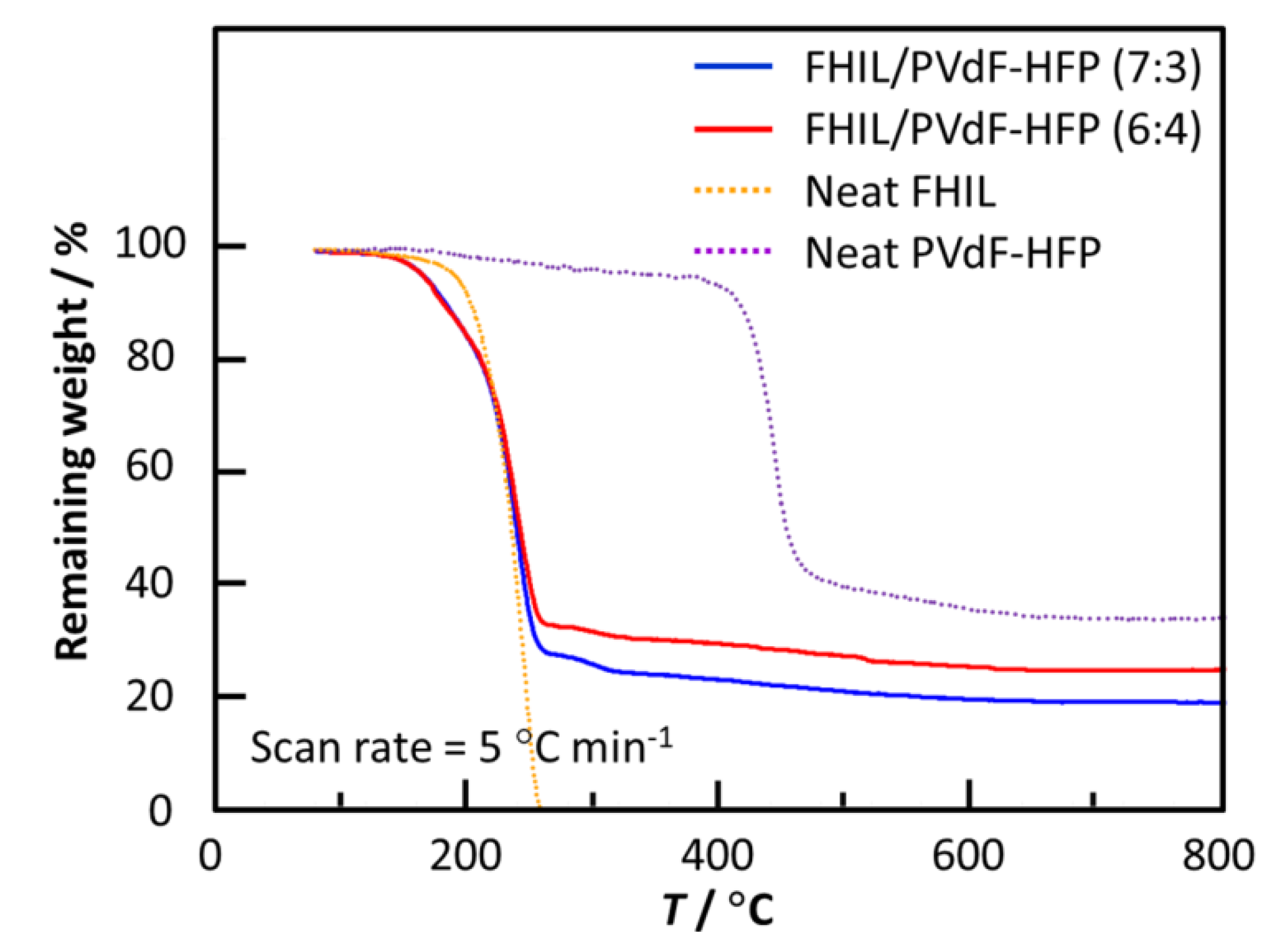
2.1. Thermal Stability

Figure 2 shows TG curves for the EMPyr(FH)1.7F/PVdF-HFP (7:3 and 6:4) composite membranes. For comparison, the TG curves of neat EMPyr(FH)1.7F and neat PVdF-HFP are also provided. All the FHIL/PVdF-HFP membranes showed similar initial weight losses at 140 °C, which is at a lower temperature than that of neat FHIL. This early weight loss is considered to be due to decomposition of some parts of PVdF-HFP, which has a melting point of about 140 °C. A second weight loss was observed at 170 °C, which corresponds to decomposition of EMPyr(FH)1.7F, as has been previously observed in EMPyr(FH)1.7F/HEMA membranes [23]. Between 250 and 600 °C, additional weight was slowly lost because of the slow decomposition of the major fraction of PVdF-HFP. However, some residues remained even at 800 °C. Since the thermal stability is determined by the initial decomposition temperature, all composite membranes were expected to be thermally stable up to 140 °C regardless of the FHIL content. This value is considered to be sufficient for fuel cell operation at 120 °C.
Figure 2. TG curves of EMPyr(FH)1.7F/PVdF-HFP (7:3 and 6:4) composite membranes, neat FHIL and neat PVdF-HFP. Scan rate: 5 °C·min−1.
Energies 08 06202 g002

2.2. Ionic Conductivity

Figure 3 shows Arrhenius plots of the ionic conductivities of the EMPyr(FH)1.7F/PVdF-HFP (7:3, 6:4, and 5:5) composite membranes. The ionic conductivities of EMPyr(FH)1.7F/HEMA (9.2:0.8) and neat EMPyr(FH)1.7F are also given for comparison. While the ionic conductivity of neat FHIL was as high as 205 mS·cm−1 at 120 °C, those of the composite membranes were lower and dependent on the FHIL content. The EMPyr(FH)1.7F/PVdF-HFP (7:3) composite membrane exhibited an ionic conductivity of 41 mS cm−1 at 120 °C, which is lower than the 82 mS cm−1 of EMPyr(FH)1.7F/HEMA (9.2:0.8). This decrease of the conductivity was attributed to its lower FHIL content. Nevertheless, this value remains impressive in comparison to those of other IL/PVdF-HFP composite membranes, as listed in Table 1.
Figure 3. Arrhenius plots of ionic conductivities of EMPyr(FH)1.7F/PVdF-HFP (7:3, 6:4 and 5:5) composite membranes, EMPyr(FH)1.7F/HEMA (9.2:0.8) composite membrane, and neat FHIL.
Energies 08 06202 g003

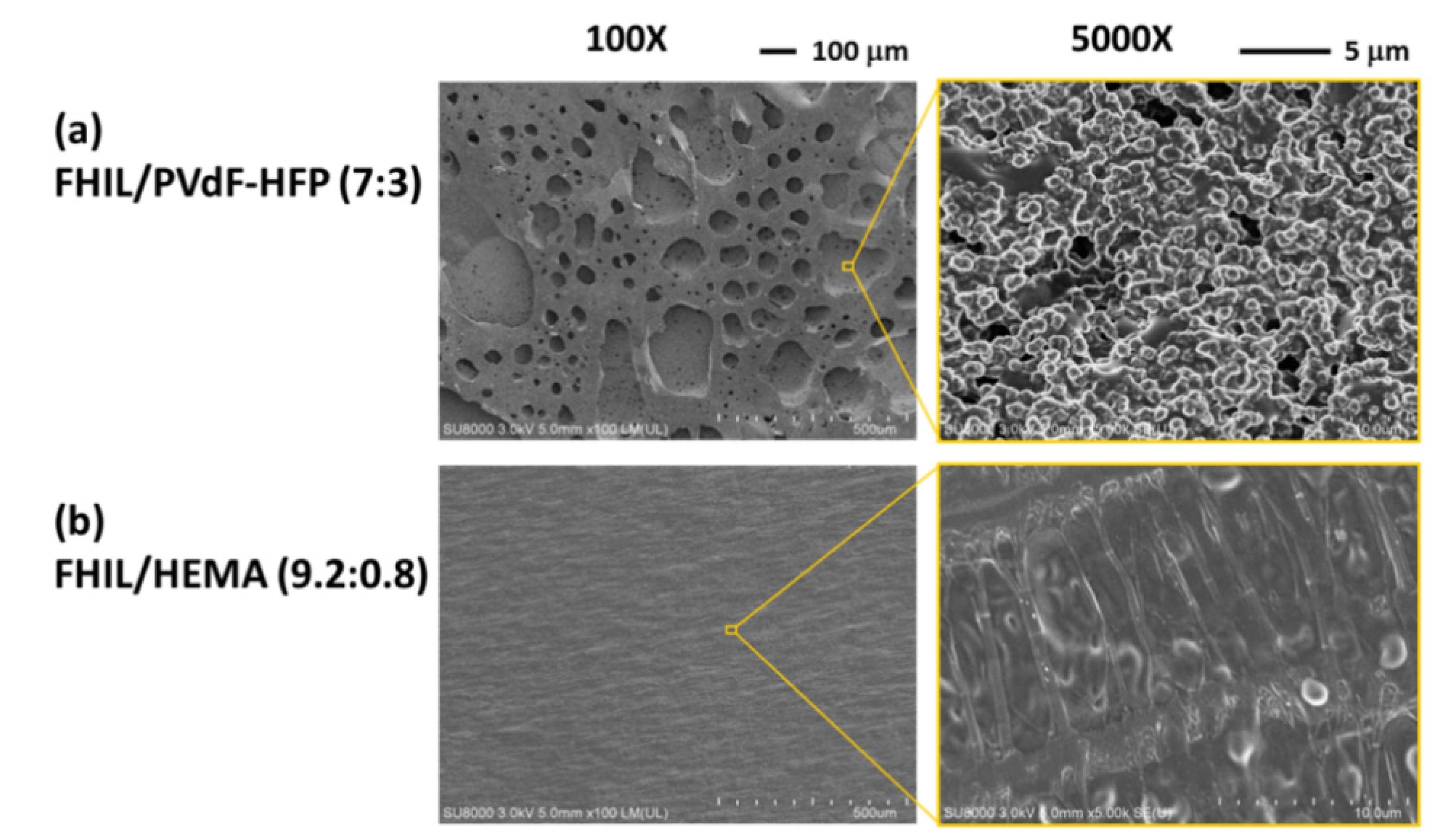
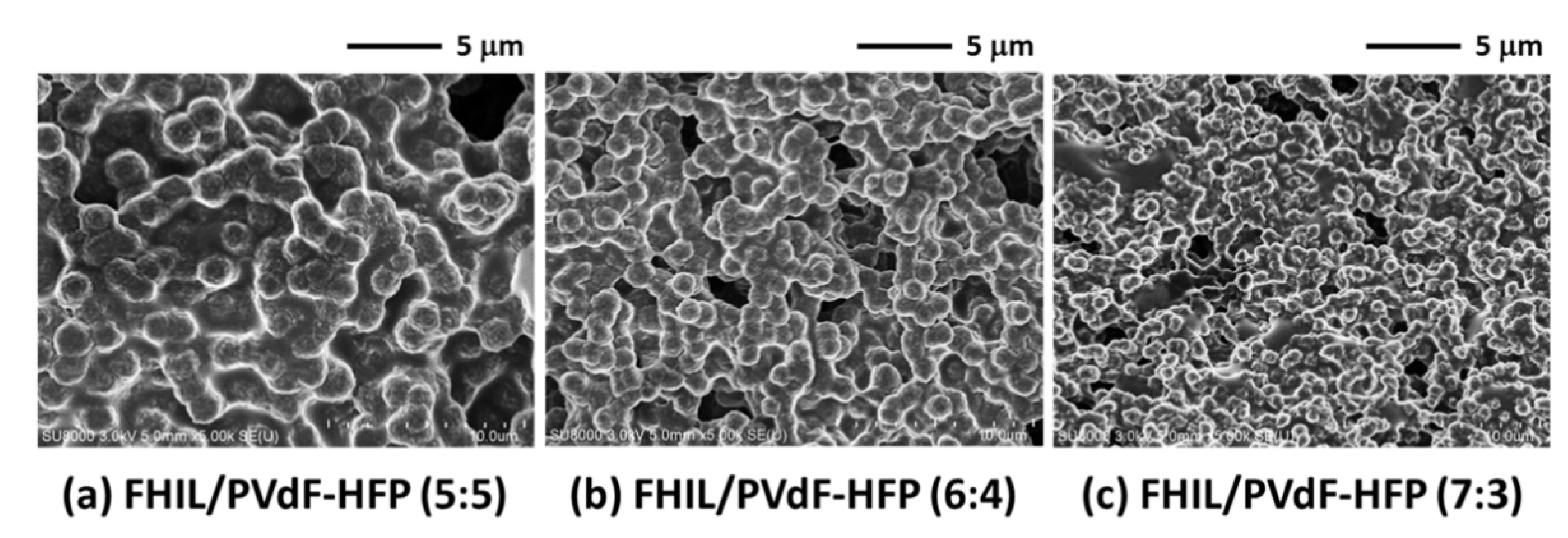
2.3. Surface Morphology

Figure 4a,b show SEM images of EMPyr(FH)1.7F/PVdF-HFP (7:3) and EMPyr(FH)1.7F/HEMA (9.2:0.8) composite membranes, respectively. While the FHIL/HEMA membrane had a rather smooth and consistent surface, the FHIL/PVdF-HFP membrane had a rough surface; this roughness is evident at both macroscopic and microscopic scales. This difference in morphology is explained by the difference in preparation method; while the FHIL/HEMA membrane was prepared by polymerizing a mixture of FHIL and HEMA monomer [23], the FHIL/PVdF-HFP membrane was prepared by casting method. In the casting method, a mixed solution of FHIL/PVdF-HFP/acetone was dried at 80 °C under an argon atmosphere. It is likely that the observed rough surface was formed during the evaporation process of acetone. These results indicate that the EMPyr(FH)1.7F/PVdF-HFP (7:3) composite membrane possessed a large membrane surface area, especially when compared with that of HEMA-based membranes. The increased membrane surface area is expected to enhance the effective three-phase boundary area and improve cell performance. In addition, the effect of FHIL content on the surface morphology of the composite membrane was also studied. Figure 5a–c show SEM images of EMPyr(FH)1.7F/PVdF-HFP membranes with FHIL/PVdF-HFP weight ratios 7:3, 6:4, and 5:5, respectively. The roughness of the membrane surface increased with increasing FHIL content in the membrane. This result is also explained by the drying process of mixed solution of FHIL/PVdF-HFP/acetone. That is, when the content of PVdF-HFP is larger, the final product is more likely to be agglomerated. Hence, the largest surface area is expected to be obtained for the membrane with a weight ratio of 7:3.
Figure 4. SEM images of (a) EMPyr(FH)1.7F/PVdF-HFP (7:3) composite membrane and (b) EMPyr(FH)1.7F/HEMA (9.2:0.8) composite membrane.
Energies 08 06202 g004
Figure 5. SEM images of EMPyr(FH)1.7F/PVdF-HFP composite membranes with the FHIL:polymer weight ratio of (a) 7:3; (b) 6:4; and (c) 5:5.
Energies 08 06202 g005

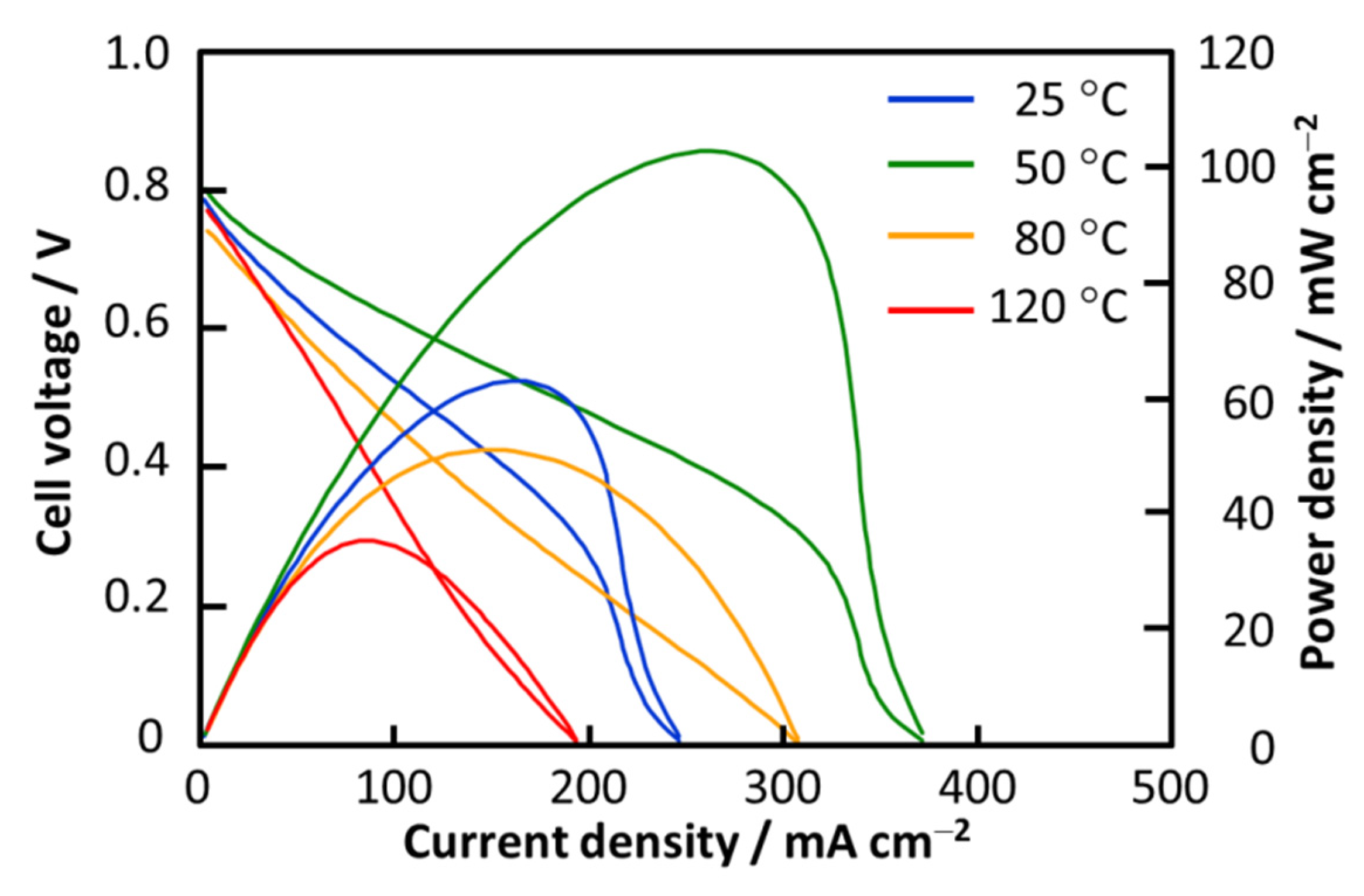
2.4. Cell Performance under Nonhumidified Conditions

Figure 6 shows current density—voltage (i–V) and current density—power density (i–P) characteristic curves for a single cell containing the EMPyr(FH)1.7F/PVdF-HFP (7:3) composite membrane. At 25 °C, a maximum power density of 63 mW·cm−2 was observed; this is the highest value ever reported for FHFCs at 25 °C. The cell performance continued to increase with increasing temperature owing to the increased electrochemical reaction rate until 50 °C, at which the maximum power density of 103 mW·cm−2 was observed. This value is very high and exceeds the 32 mW·cm−2 of a single cell using an EMPyr(FH)1.7F/HEMA (9.2:0.8) composite membrane at the same temperature [23]. However, the cell performance deteriorated above 80 °C. This deterioration trend is similar to that of cells containing FHIL/HEMA membranes [23]. The problem is explained as follows: At higher temperatures, the composite electrolyte softens and penetrates into the gas diffusion electrodes, which partially plugs the gas channels in the gas diffusion layer. While the theoretical open circuit voltage (OCV) values are around 1.23 V at room temperature, the i–V curves show low OCV values of about 0.8 V, which is commonly observed in ionic liquid-based polymer electrolyte membranes for fuel cells. It was revealed recently that protic organic ionic plastic crystals (POIPCs), which are also organic salts, could exhibit high OCVs during device evaluation, approaching the theoretical values at 150 °C [31].
Figure 6. iV and iP characteristic curves of a single cell using EMPyr(FH)1.7F/PVdF-HFP (7:3) composite membrane at 25−120 °C under nonhumidified conditions. Anode and cathode catalyst: 1.0 mg Pt·cm−2.
Energies 08 06202 g006

2.5. In Situ a.c. Impedance

To elucidate the cause of performance deterioration, in situ a.c. impedance analysis was carried out along with the single cell tests. Figure 7a shows a Nyquist plot of a single cell with an EMPyr(FH)1.7F/PVdF-HFP (7:3) composite membrane at 0.6 V. The first x-intercept corresponds to the bulk (or Ohmic) resistance while the next two semicircles represent the resistances from charge transfer and mass transfer, respectively. To approximate each resistance, the resultant Nyquist plot was fitted to an equivalent circuit. Figure 7b exhibits the temperature dependences of the bulk resistance (Rb), charge transfer resistance (RCT), mass transfer resistance (RMT), and total resistance (Rtot). Rb decreased with temperature because of the increased ionic conductivity. The change in Rb was, however, negligible because its value was very small relative to the total resistance. On the other hand, RMT significantly increased when the temperature was elevated from 50 to 80 °C. This result reflects the poor mobility of the reactant gases to the three-phase boundary above 50 °C, which is consistent with the speculation that the gas channels were obstructed by the softened composite electrolyte, as mentioned in Section 2.4. Similarly, RCT also significantly increased with increasing temperature from 50 to 80 °C. The reason is as follows: at elevated temperatures, the softened composite electrolyte penetrates into both the catalyst layer and gas diffusion layer. Since the majority of the catalyst layer is fully filled with electrolyte, the effective three-phase boundary area decreases. Thus, the catalyst was ineffectively utilized, resulting in increased RCT.
Figure 7. (a) Nyquist plot of a single cell using EMPyr(FH)1.7F/PVdF-HFP (7:3) composite membrane, operated from 25 to 120 °C under nonhumidified conditions and (b) temperature dependences of bulk resistance (Rb), charge transfer resistance (RCT), mass transfer resistance (RMT), and total resistance (Rtot).
Energies 08 06202 g007

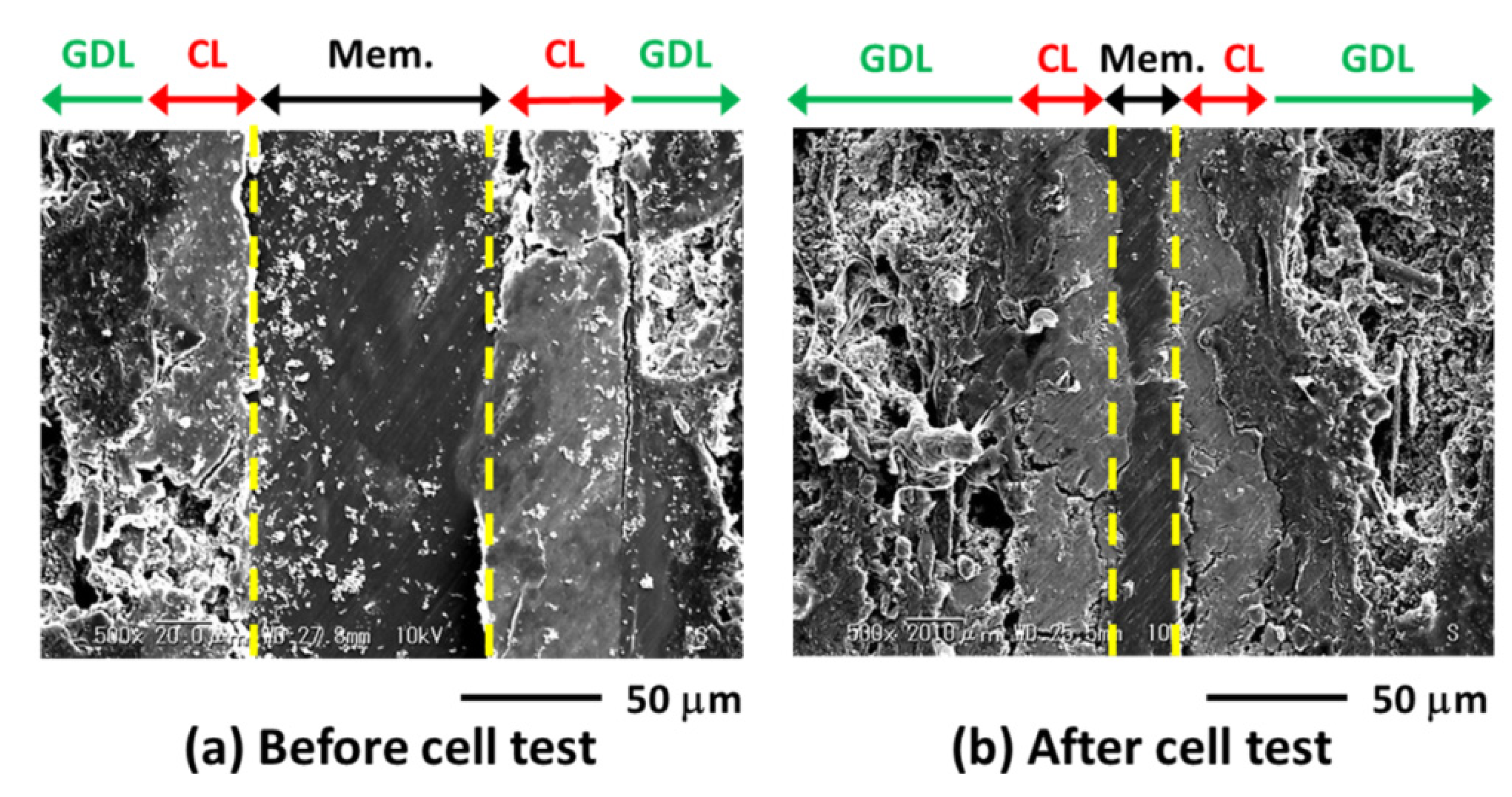
2.6. Cross-Sectional SEM Image

To verify whether the composite electrolyte softened, cross-sectional SEM observations of the MEAs before and after the cell test were performed, as shown in Figure 8.
Figure 8. Cross-sectional SEM images of the MEAs using EMPyr(FH)1.7F/PVdF-HFP (7:3) composite membrane (a) before and (b) after cell test at 25−120 °C. (GDL = gas diffusion layer, CL = catalyst layer, Mem. = membrane).
Energies 08 06202 g008
The dashed lines indicate the interface between the membrane and catalyst layer. Before the cell test, the membrane (Mem.), catalyst (CL), and gas diffusion (GDL) layers were in good contact with each other. However, after the cell test, the membrane thickness decreased, indicating softening of the membrane. The softened electrolyte then escaped from the original location and penetrated into both the CL and GDL, thereby decreasing the three-phase boundary area of the CL and plugging the gas channels in the GDL. This result well explains the increase in the RCT and RMT values at 80 °C in the a.c. impedance analysis. Concerning the shortcoming of PVdF-HFP copolymer as the host matrix for ionic liquids for the application in high temperature (100−200 °C), poly(ionic liquid) is considered as one type of promising membrane matrix for ionic liquids [32]. Another possible method to improve the mechanical strength of membranes at high temperature is the use of membrane support which has high heat-resisting properties like polyimide [33].

3. Experimental Section

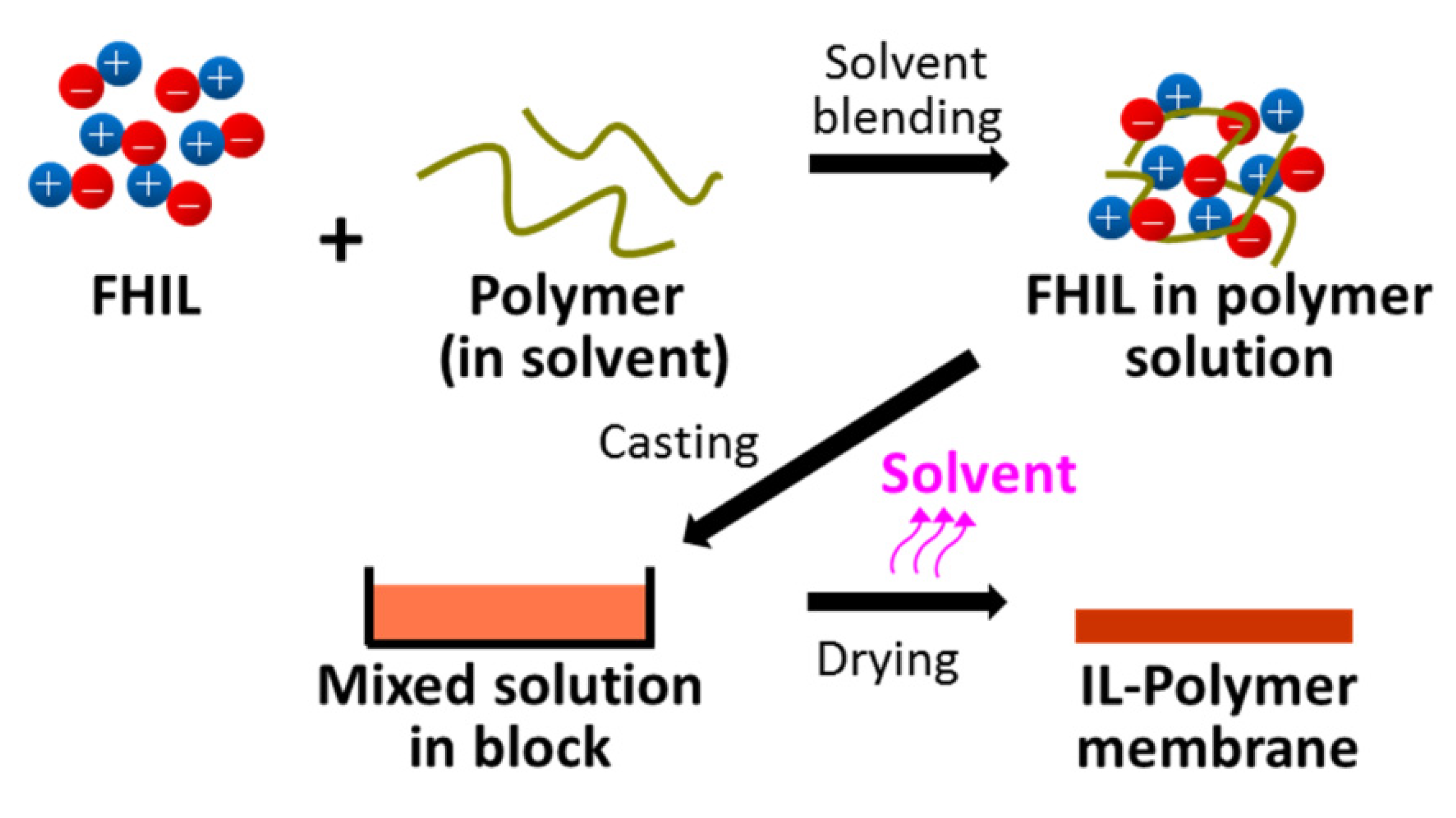
3.1. Preparation of EMPyr(FH)1.7F/PVdF-HFP Composite Membranes

EMPyr(FH)2.3F was prepared using a previously reported method [10,12]. EMPyr(FH)1.7F, which has a negligible vapor up to 120 °C, was obtained by further evacuating EMPyr(FH)2.3F using a rotary pump through a chemical trap for four days and then directly through a cold trap for two days at 120 °C under reduced pressure (<1 Pa). The n value of 1.7 was confirmed by elemental analysis of hydrogen, carbon, nitrogen, and fluorine using a CHN coder and a fluoride-ion selective electrode.
Scheme 1 shows the procedure for preparation of the composite membranes. Firstly, PVdF-HFP (Mn = 110000, Aldrich, St. Louis, MO, USA) was dissolved in acetone (99.9%, Wako, Osaka, Japan) to prepare a 5 wt% PVdF-HFP solution. EMPyr(FH)1.7F was added to the polymer solution at FHIL/polymer weight ratios of 7:3, 6:4, and 5:5. This method differs from the previously reported method for the preparation of FHIL/HEMA membranes in that no membrane support was used. The mixed solution was stirred for >1 h using a magnetic stirrer until a homogeneous solution was obtained. Then, it was cast onto perfluoroalkoxy (PFA) Petri dishes and dried at 80 °C for 12 h under an argon atmosphere. Finally, the composite membranes were peeled from the Petri dishes.
Scheme 1. Preparation procedure of EMPyr(FH)1.7F/PVdF-HFP composite membrane.
Energies 08 06202 g009

3.2. Characterization of EMPyr(FH)1.7F/PVdF-HFP Composite Membranes

The thermal stabilities of the prepared membranes were determined via thermogravimetric (TG) analysis using a differential thermogravimetric analyzer (Thermo plus EVO2, Rigaku, Tokyo, Japan). The analysis was conducted in the temperature range of 25–800 °C at a scanning rate of 5 °C·min−1 under an argon atmosphere. Platinum pans were used because of their excellent chemical resistance to FHILs. The ionic conductivities of the composite membranes were measured in the longitudinal direction using a four-point probe method. Measurements were carried out from −40 to 120 °C under a nitrogen atmosphere using an a.c. impedance method with a Solartron 1286 electrochemical interface combined with a Solartron 1260 frequency response analyzer (AMETEK, Farnborough, UK). Field emission scanning electron microscopy (FE-SEM; SU-8020, Hitachi, Tokyo, Japan) was utilized to observe the membrane surface morphologies. Prior to the observation, the membrane samples were coated with platinum using ion-sputtering equipment (MC-100, Hitachi).

3.3. Membrane Electrode Assembly (MEA) Fabrication and Single Cell Test

The MEA was prepared by placing the composite membrane directly between two gas diffusion electrodes (GDEs, 1.0 mg Pt·cm−2, ionomer free, KM Lab, Yamato, Japan) with geometric surface areas of 1 cm2. In the present study, the use of ionomeric binder in the CL was not tired because the appropriate method had not been developed. After incorporating the MEA into a single cell with fuel cell hardware (EFC-01-02, 1 cm2, ElectroChem, Woburn, MA, USA), single cell tests were conducted using a Solartron 1286 electrochemical interface in a temperature-controlled chamber at 25–120 °C under nonhumidified conditions. Anhydrous H2 (99.999%) was supplied by a hydrogen generator (HORIBA STEC, Kyoto, Japan), and O2 was supplied from a cylinder (99.9999%, Kyoto Teisan, Kyoto, Japan); their flow rates were set at 10 mL·min−1.

3.4. In Situ a.c. Impedance Analysis

Along with the fuel cell operation, in situ a.c. impedance analysis was also performed. A Solartron 1260 frequency response analyzer (AMETEK, Farnborough, UK) combined with a Solartron 1286 electrochemical interface (AMETEK) was used to provide a.c. signal and analyze the responding impedance. An a.c. potential of 10 mV was applied to the single cell as an excitation signal under a constant cell voltage of 0.6 V. The frequency range was from 20 kHz to 20 mHz. The approximate values of bulk resistance, charge transfer resistance, and mass transfer resistance were determined by fitting the resultant Nyquist plots with a suitable equivalent circuit.

3.5. Cross-sectional SEM Observation

MEA samples from before and after the cell test were cut using a knife and embedded into a resin block using a resin mounting kit (20-3570, VariDur®, Buehler, Lake Bluff, IL, USA). The prepared sample block was then consecutively polished with No. 300, 600, 1200, 2000, and 3000 emery papers on a rotating stage (100 rpm) to expose the cross-sectional area. The exposed surface was coated with gold using ion-sputtering equipment (E-1010, Hitachi) and then observed via SEM (VE-8800, Keyence, Osaka, Japan).

4. Conclusions

Composite membranes consisting of EMPyr(FH)1.7F IL and PVdF-HFP copolymer were successfully prepared by a casting method using acetone as the solvent. The prepared membranes had rough surfaces, which could enlarge the three-phase boundaries. For the EMPyr(FH)1.7F/PVdF-HFP (7:3 weight ratio) composite membrane, the ionic conductivity was 41 mS·cm−1 at 120 °C. In a single cell test, a maximum power density of 103 mW·cm−2 was observed at 50 °C under nonhumidified conditions, which is the highest value among reported FHFCs. However, the cell performance decreased at 80 °C. According to in situ a.c. impedance analyses and cross-sectional SEM observations of the MEAs, the deterioration was caused by penetration of the softened composite electrolyte into the gas diffusion electrodes, which decreased the three-phase boundary area in the CL and plugged gas channels in the GDL.

Author Contributions

P.K., T.N. and R.H. developed the concept. P.K. and T.N. designed the experiments. P.K. performed the experiments and analyzed the data. P.K., T.N. and R.H. prepared the manuscript.

Conflicts of Interest

The authors declare no conflict of interest.

References

  1. Li, Q.F.; Hjuler, H.A.; Bjerrum, N.J. Oxygen reduction on carbon supported platinum catalysts in high temperature polymer electrolytes. Electrochim. Acta 2000, 45, 4219–4226. [Google Scholar]
  2. Yang, C.; Costamagna, P.; Srinivasan, S.; Benziger, J.; Bocarsly, A.B. Approaches and technical challenges to high temperature operation of proton exchange membrane fuel cells. J. Power Sources 2001, 103, 1–9. [Google Scholar] [CrossRef]
  3. Kreuer, K.D.; Paddison, S.J.; Spohr, E.; Schuster, M. Transport in proton conductors for fuel-cell applications:  simulations, elementary reactions, and phenomenology. Chem. Rev. 2004, 104, 4637–4678. [Google Scholar] [CrossRef] [PubMed] [Green Version]
  4. Meier, F.; Eigenberger, G. Transport parameters for the modelling of water transport in ionomer membranes for PEM-fuel cells. Electrochim. Acta 2004, 49, 1731–1742. [Google Scholar] [CrossRef]
  5. Seddon, K.R. Ionic liquids for clean technology. J. Chem. Technol. Biotechnol. 1997, 68, 351–356. [Google Scholar] [CrossRef]
  6. Welton, T. Room-temperature ionic liquids: Solvents for synthesis and catalysis. Chem. Rev. 1999, 99, 2071–2084. [Google Scholar] [CrossRef] [PubMed]
  7. Wasserscheid, P.; Kein, W. Ionic liquids—New “solutions” for transition metal catalysis. Angew. Chem. Int. Ed. 2000, 39, 3772–3789. [Google Scholar] [CrossRef]
  8. Hagiwara, R.; Hirashige, T.; Tsuda, T.; Ito, Y. Acidic 1-ethyl-3-methylimidazolium fluoride: A new room temperature ionic liquid. J. Fluor. Chem. 1999, 99, 1–3. [Google Scholar] [CrossRef]
  9. Hagiwara, R.; Ito, Y. Room temperature ionic liquids of alkylimidazolium cations and fluoroanions. J. Fluor. Chem. 2000, 105, 221–227. [Google Scholar] [CrossRef]
  10. Hagiwara, R.; Hirashige, T.; Tsuda, T.; Ito, Y. A highly conductive room temperature molten fluoride: EMIF 2.3 HF. J. Electrochem. Soc. 2002, 149, D1–D6. [Google Scholar] [CrossRef]
  11. Hagiwara, R.; Matsumoto, K.; Nakamori, Y.; Tsuda, T.; Ito, Y.; Matsumoto, H.; Momota, K. Physicochemical properties of 1,3-dialkylimidazolium fluorohydrogenate room-temperature molten salts. J. Electrochem. Soc. 2003, 150, D195–D199. [Google Scholar] [CrossRef]
  12. Matsumoto, K.; Hagiwara, R.; Ito, Y. Room-temperature ionic liquids with high conductivities and wide electrochemical windows. Electrochem. Solid-State Lett. 2004, 7, E41–E44. [Google Scholar] [CrossRef]
  13. Matsumoto, K.; Ohtsuki, J.; Hagiwara, R.; Matsubara, S. Cesium fluorohydrogenate, Cs(FH)2.3F. J. Fluor. Chem. 2006, 127, 1339–1343. [Google Scholar] [CrossRef]
  14. Yamagata, M.; Konno, S.; Matsumoto, K.; Hagiwara, R. Room-temperature fluorohydrogenate ionic liquids of alkylpyridinium cations and allylated quaternary cyclic ammonium cations. Electrochem. Solid-State Lett. 2009, 12, F9–F12. [Google Scholar] [CrossRef]
  15. Kanematsu, S.; Matsumoto, K.; Hagiwara, R. Electrochemically stable fluorohydrogenate ionic liquids based on quaternary phosphonium cations. Electrochem. Commun. 2009, 11, 1312–1315. [Google Scholar] [CrossRef]
  16. Enomoto, T.; Kanematsu, S.; Tsunashima, K.; Matsumoto, K.; Hagiwara, R. Physicochemical properties and plastic crystal structures of phosphonium fluorohydrogenate salt. Phys. Chem. Chem. Phys. 2011, 13, 12536–12544. [Google Scholar] [CrossRef] [PubMed] [Green Version]
  17. Taniki, R.; Matsumoto, K.; Hagiwara, R. Trialkylsulfonium fluorohydrogenate giving the highest conductivity in room temperature ionic liquids. Electrochem. Solid-State Lett. 2012, 15, F13–F15. [Google Scholar] [CrossRef] [Green Version]
  18. Taniki, R.; Matsumoto, K.; Hagiwara, R. Synthesis and characterization of fluorohydrogenate ionic liquids based on azoniaspiro-type cations. Chem. Lett. 2013, 42, 1469–1471. [Google Scholar] [CrossRef]
  19. Hagiwara, R.; Nohira, T.; Matsumoto, K.; Tamba, Y. A fluorohydrogenate ionic liquid fuel cell operating without humidification. J. Electrochem. Solid-State Lett. 2005, 8, A231–A233. [Google Scholar] [CrossRef]
  20. Lee, J.S.; Nohira, T.; Hagiwara, R. Novel composite electrolyte membranes consisting of fluorohydrogenate ionic liquid and polymers for the unhumidified intermediate temperature fuel cell. J. Power Sources 2007, 171, 535–539. [Google Scholar] [CrossRef]
  21. Tani, Y.; Nohira, T.; Enomoto, T.; Matsumoto, K.; Hagiwara, R. Solubility and diffusion coefficient of oxygen in 1-ethyl-1-methylpyrrolidinium fluorohydrogenate room temperature ionic liquid at 298–373 K. J. Electrochim. Acta 2011, 56, 3852–3856. [Google Scholar] [CrossRef]
  22. Kiatkittikul, P.; Yamaguchi, J.; Taniki, R.; Matsumoto, K.; Nohira, T.; Hagiwara, R. Influence of cationic structures on oxygen reduction reaction at Pt electrode in fluorohydrogenate ionic liquids. J. Power Sources 2014, 266, 193–197. [Google Scholar] [CrossRef]
  23. Kiatkittikul, P.; Nohira, T.; Hagiwara, R. Nonhumidified fuel cell using N-ethyl-N-methylpyrrolidinium fluorohydrogenate ionic liquid-polymer composite membranes. J. Power Sources 2012, 220, 10–14. [Google Scholar] [CrossRef]
  24. Navarra, M.A.; Panero, S.; Scrosati, B. Novel, ionic-liquid-based, gel-type proton membranes. Electrochem. Solid-State Lett. 2005, 8, A324–A327. [Google Scholar] [CrossRef]
  25. Sekhon, S.S.; Singh Lalia, B.; Park, J.S.; Kim, C.S.; Yamada, K. Physicochemical properties of proton conducting membranes based on ionic liquid impregnated polymer for fuel cells. J. Mater. Chem. 2006, 16, 2256–2265. [Google Scholar] [CrossRef]
  26. Sekhon, S.S.; Krishnan, P.; Singh Lalia, B.; Yamada, K.; Kim, C.S. Proton conducting membrane containing room temperature ionic liquid. Electrochim. Acta 2006, 52, 1639–1644. [Google Scholar] [CrossRef]
  27. Singh Lalia, B.; Sekhon, S.S. Polymer electrolytes containing ionic liquids with acidic counteranion (DMRImH2PO4, R = ethyl, butyl and octyl). Chem. Phys. Lett. 2006, 425, 294–300. [Google Scholar] [CrossRef]
  28. Fernicola, A.; Panero, S.; Scrosati, B.; Tamada, M.; Ohno, H. New types of Brönsted acid-base ionic liquids-based membranes for applications in PEMFCs. ChemPhysChem 2007, 8, 1103–1107. [Google Scholar] [CrossRef] [PubMed]
  29. Fernicola, A.; Navarra, M.A.; Panero, S. Aprotic ionic liquids as electrolyte components in protonic membranes. J. Appl. Electrochem. 2008, 38, 993–996. [Google Scholar] [CrossRef]
  30. Malis, J.; Mazur, P.; Schauer, J.; Paidar, M.; Bouzek, K. Polymer-supported 1-butyl-3-methylimidazolium trifluoromethanesulfonate and 1-ethylimidazolium trifluoromethanesulfonate as electrolytes for the high temperature PEM-type fuel cell. Int. J. Hydrog. Energy 2013, 38, 4697–4704. [Google Scholar] [CrossRef]
  31. Luo, J.; Jensen, A.H.; Brooks, N.R.; Sniekers, J.; Knipper, M.; Aili, D.; Li, Q.; Vanroy, B.; Wubbenhorst, M.; Yan, F.; et al. 1,2,4-Triazolium perfluorobutanesulfonate as an archetypal pure protic organic ionic plastic crystal electrolyte for all-solid-state fuel cells. Energy Environ. Sci. 2015, 8, 1276–1291. [Google Scholar] [CrossRef]
  32. Wang, P.; Zhou, Y.N.; Luo, J.S.; Luo, Z.H. Poly(ionic liquid)s-based nanocomposite polyelectrolytes with tunable ionic conductivity prepared via SI-ATRP. Polym. Chem. 2014, 5, 882–891. [Google Scholar]
  33. Kiatkittikul, P.; Nohira, T.; Hagiwara, R. Advantage of a polyimide membrane support in nonhumidified fluorohydrogenate-polymer composite fuel cells. Fuel Cells 2015. [Google Scholar] [CrossRef] [Green Version]

