Methods of Ferroresonance Mitigation in Voltage Transformers in a 30 kV Power Supply Network


1
Department of Electrical and Power Engineering, AGH University of Science and Technology, al. Mickiewicza 30, 30-059 Krakow, Poland
2
ELECON Sp. z o.o., Rybnicka 20, 43-190 Mikolow, Poland
*
Author to whom correspondence should be addressed.
Energies 2022, 15(24), 9516; https://doi.org/10.3390/en15249516
Submission received: 10 November 2022
/
Revised: 4 December 2022
/
Accepted: 13 December 2022
/
Published: 15 December 2022
(This article belongs to the Section F: Electrical Engineering)
Abstract
:Inductive voltage transformers are the basic components of the switchgear equipment or electrical substations. This article presents problems related to their operation. Inductive voltage transformers were exposed to specific working conditions in the form of ferroresonance oscillations with the participation of measurement and protective transformers. The disadvantage and negative significance of the phenomenon contributed to the development of the most convenient elimination methods, which is the main goal and achievement of the publication. The analysis of the proposed solutions were carried out on a theoretical model of a 30 kV power network model created and run in the Electromagnetic Transients Program/Alternative Transients Program (EMTP/ATP). The article presents several results of computer simulations carried out together with their complete characteristics (phase voltage waveforms on the primary side of voltage transformers), which allowed us to indicate the disadvantages and advantages of the solutions developed, and choose the most favorable methods to eliminate nonlinear oscillations. In the article, we present an analysis of all aspects contributing to the solution to the problem. This has permitted an appropriate conclusion to be made indicating the advantage of the method based on the use of a damping resistor in the open delta circuit compared to other solutions. Current solutions are largely based on a product using active variation of the resistance of an open delta attached resistor. The concept in this paper is based on a fixed resistance value, which is a different approach to the problem. By using a switch, the resistor is only connected when a fault occurs. Thanks to this solution, the secondary winding of the open delta is not additionally loaded (despite the very high resistance) at all times during the operation of the power network, as is the case with the available solution.
1. Introduction
The constant development of power engineering in many areas encourages the creation of new concepts regarding the measuring apparatus used. Modern transmission and distribution networks are becoming increasingly advanced, as are smart grids [1,2,3,4]. The wide availability of materials, innovative solutions improving the parameters of power devices, and the assurance of adequate confidence in the operation of systems are only a few aspects considered by producers in terms of voltage transformers.
Voltage transformers are devices that allow the measurement of voltage in electrical circuits included in the power system. They are characterized by low short circuit voltage and low nominal power. They are not directly involved in the processing of electrical energy at high power. In the rated operation condition, as well as in an emergency condition, they should be distinguished by the correct voltage transformation [5]. Their absence in the system would significantly limit the possibility of controlling the work of networks and power systems, constituting the primary source of signals used in protective automation systems.
The main structural element of voltage transformers is a ferromagnetic core. Because it is characterized by the nonlinearity of the magnetic circuit, the formation of non-standard operating conditions of the power network contributes to the possibility of undesirable phenomena affecting the functioning of voltage transformers [6,7,8]. One of them concerns ferroresonant oscillations [9]. The negative aspect of this state is associated with the effects of damage, and voltage transformer explosions in extreme cases [10]. The main goal set for the constructors of voltage transformers is to make power devices in a way that allows them to be protected against the negative influence of ferroresonance or to limit the possibility of its occurrence.
Bearing in mind the unfavorable impact of nonlinear oscillations on measuring and/or security units, the main objective of this work is to present and characterize this phenomenon with an indication of methods as to how to eliminate it in the form of damping. Primary attention here is focused on inductive voltage transformers of medium voltage. On this basis, a comparison was made between the available methods and a selection of the most convenient ferroresonance minimization technologies. Based on the analysis, the most effective methods of damping nonlinear vibrations can be identified. An important part of the article is the simulations made in the EMTP/ATP program, which was developed for the 30kV power grid using the listed elimination paths. Such an approach allowed a clear indication of the best method of suppressing ferroresistant oscillations.
2. Introduction and Theory
The wide range of rated voltages used in power systems contributes to the use of measuring equipment that allows it to be installed in any system. This aspect is also focused on voltage transformers. Providing basic properties and parameters as well as the required measurement accuracy means that, nowadays, various structures are manufactured and widely analyzed.
Depending on the number of phases to which the primary winding of the voltage transformer is connected, the following units are distinguished: single- and three-phase units. Single-phase units are characterized by a wide range of applications for almost every value of the rated voltage. Three-phase structures are most often used in the voltage range not exceeding several dozen kilovolts.
2.1. Essential Characteristics of Ferroresonance with the Participation of Voltage Transformers
Voltage transformers belong to a group of devices whose presence is necessary for the proper operation of power systems. The equipment of transformers in ferromagnetic cores causes structures to be susceptible to the occurrence of the ferroresonance phenomenon that disturb the normal functioning of power grids.
Ferroresonant oscillations occur due to a combination of system capacitive reactance with the nonlinear inductive reactance of voltage transformers [11]. The condition for the phenomenon is the mutual adjustment of the parameters presented.
The formation of nonlinear oscillation may occur due to two different configurations specifying the manner of the reactance jointly. These arrangements include:
- Serial connection—in the case of a serial combination of capacitance together with nonlinear inductance;
- Parallel connection—in the presence of a parallel combination of capacitance with nonlinear inductance.
The method of integrating elements conducive to the formation of ferroresonant oscillations contributes to the initiation of the proper character of the phenomenon [12]. A serial connection causes voltage ferroresonance initiation, while a parallel compilation causes ferroresonance of currents. Each type of oscillation is associated with the possibility of its occurrence with the voltage value of a given fragment of the power grid. This also applies to the manner of how the neutral point of the network is to be connected to earth, which in the case of medium voltages (MV) can be isolated or grounded by a choke or resistor. A high-voltage network (HV) works with an effectively grounded neutral point. Such configurations contribute to the occurrence of ferroresonant currents in MV networks with an isolated neutral point and ferroresonant voltages in HV systems [13,14].
Pulses that have a decisive effect on the formation of nonlinear oscillation include sudden changes in voltage, load changes [15], and changes to the network configuration [16]. Their effects result in a significant overvoltage and overcurrent [17,18]. The ferroresonance phenomenon is classified as a group of temporary overvoltages for which oscillations are non-damping or poor damping. The duration can be maintained for a long time. The oscillation result is to saturate the cores of transformers and increase the value of currents in primary winding [19]. Deformation of voltage and current waveforms during the ferroresonance phenomenon may occur both for fundamental frequencies and for subharmonics and higher harmonics. This contributes to the possibility of a few solutions specifying nonlinear inductance and capacitance for which a condition for nonlinear oscillations is met.
2.2. Favorable Conditions for the Formation of the Ferroresonance Phenomenon
A mutual connection of capacitance and nonlinear inductance creates the possibility of ferroresonant oscillations. The sources of the presented parameters are many. In the case of capacitance, the capacitance of power cables, overhead lines, capacitor batteries, and shunt capacitors of the circuit breaker must be taken into account. The use of capacitance-voltage transformers attests to the need for them to be considered in the determination of the resultant layout capacitance.
A significant number of elements affecting the forming of the phenomenon and the method of their interrelations result in the fact that ferroresonance initiation conditions are met for different configurations [20]. Of the systems susceptible to nonlinear oscillation, the most important cases regarding voltage transformers were selected. They belong to the following:
- (1)
- The installation of three induction voltage transformers in a three-phase system with different magnetization characteristics. This issue can be related to the use of power devices of various types or their assembly by other manufacturers.
- (2)
- The opening of multi-break circuit breakers connected in parallel with the capacitors controlling voltage distribution to which HV inductive transformers are connected. In the presence of disconnectors, an essential aspect is their proper closure enabling the creation of a system susceptible to series ferroresonance.
- (3)
- The performance of switching operations or occurrence of an earth fault in the MV network structure operating with an isolated neutral point and equipped with inductive voltage transformers.
- (4)
- The presence of an unbalanced load of inductive voltage transformers installed in the MV system.
- (5)
- A break in the circuit due to a blown fuse located in the primary part of the group of three inductive voltage transformers in the MV system.
- (6)
- No synchronization of switching three MV inductive voltage transformers on or off with the use of single-pole disconnectors.
The configurations presented do not determine the necessity of ferroresonance in the system. This is related to the complexity of the phenomenon itself and the change in the values of the system parameters under the influence of, among others, the expansion or modernization of the network, causing the inability to initiate non-linear vibrations [21].
2.3. Ferroresonant Vibrations and a Sign of Their Occurrence
Nonlinear oscillations, despite their complicated analysis, the complexity of the processes taking place, and difficulties in predicting the potential occurrence, contribute to the formation of characteristic symptoms indicating the phenomenon’s presence [22,23]. The most common symptoms accompanying ferroresonant vibrations in voltage transformers include large overvoltages and overcurrents, significant and constant distortion of voltage and current waveforms, continuous and excessively loud noise, overheating, a voltage higher than the phase-to-earth voltage in an open triangle circuit, and voltmeter fluctuations [5,24]. An essential aspect in this context comprises properly conducted monitoring and diagnostics of ferroresonance phenomena [25,26].
2.4. Methods of Elimination of the Ferroresonance Phenomenon
The main goal set for designers of power systems is to create structures that protect voltage transformers against the negative effects of ferroresonance or reduce the possibility of its occurrence, by initially making specifications using modern nonlinear techniques of analysis to define both safe and unsafe zones of operation [27]. Therefore, extensive countermeasures are undertaken to eliminate nonlinear oscillations. The most common solutions include the following:
- (1)
- Application of anti-ferrorresonance transformers.
- (2)
- Switching on the damping resistor in the open delta circuit.
- (3)
- Application of fuses located in the primary circuits of voltage transformers.
- (4)
- Grounding through the transformer star point resistor.
- (5)
- Installing suppression resistors, in each phase, located in the secondary windings connected in a star [28].
- (6)
- Series connection of a very low-value resistor and saturable reactor.
- (7)
- Connecting additional to-ground capacity to the busbars in order to detach the circuit from ferroresonant vibrations.
The ferroresonance phenomenon may be mitigated by the installation of a zigzag-grounding transformer [29]. Research has also been conducted on the use of memristors to reduce overvoltage and overcurrents in inductive voltage transformers [30], the application of neural networks, and time–domain analysis for overcurrent relay [31].
3. Model of the Power Grid
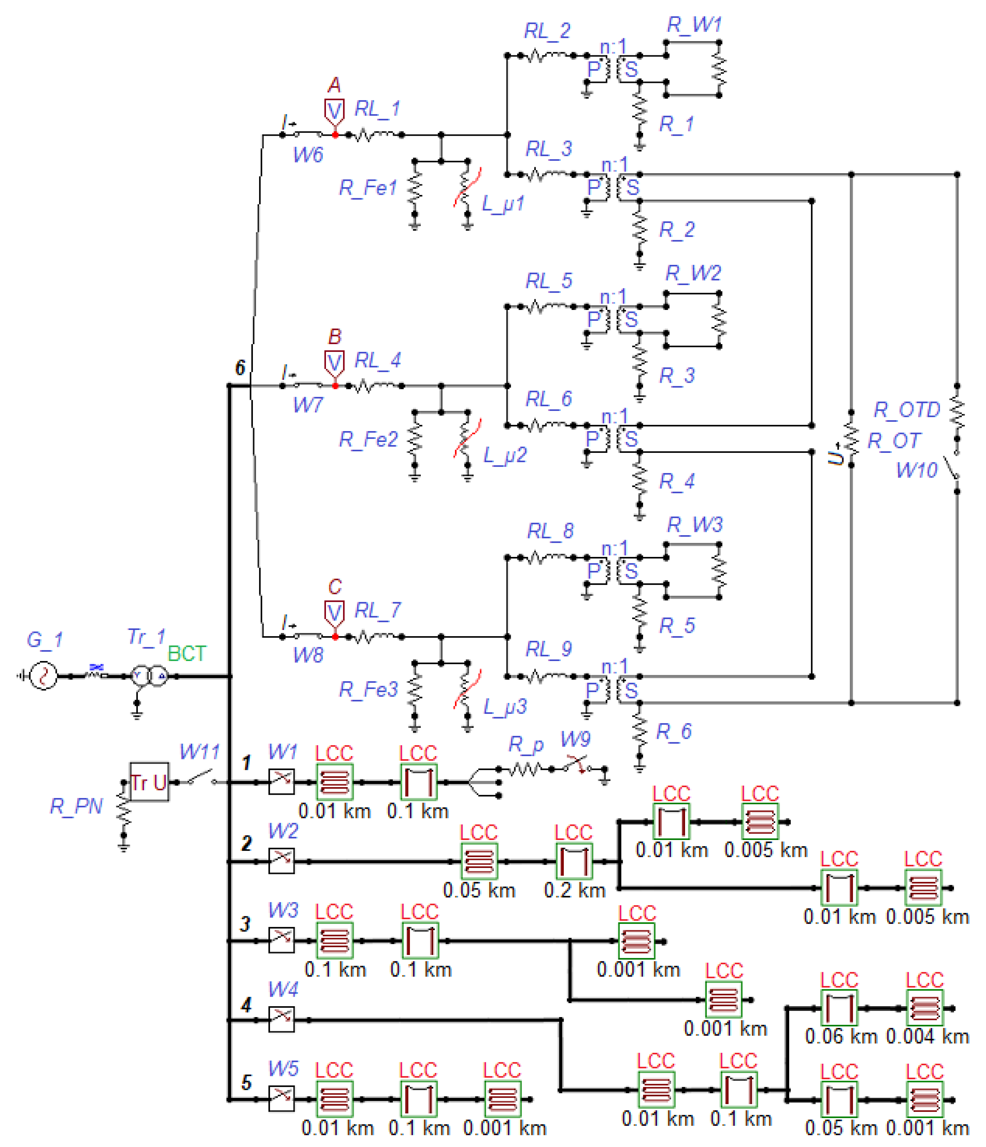
The subject of the study is a fragment of the power grid with a voltage of 30 kV, operating with an isolated neutral point. Figure 1 shows a diagram of the structure implemented, as created in an EMTP/ATP program.
The system is supplied from the G_1 power system through the Tr_1 power transformer. The structural elements include the presence of five receiving fields equipped with a cable and overhead lines, and one measurement field with a system of three identical inductive voltage transformers. Each module is equipped with a switch with an appropriate marking ranging from W1 to W8.
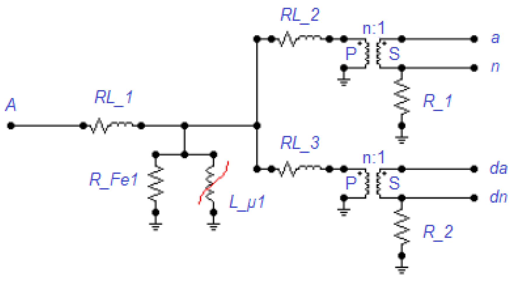
The diagram of the voltage transformer for phase L1 is shown in Figure 2. The key elements of the model include:
- RL_1—resistance and leakage inductance of the primary winding.
- RL_2—resistance and leakage inductance of the secondary winding, reduced to the primary side.
- RL_3—resistance and leakage inductance of the open delta winding, reduced to the primary side.
- R_Fe1—resistance representing active power losses in the core.
- R_1, R_2 —earth resistance.
- L_μ1—nonlinear magnetization inductance.
- A—primary winding terminal.
- A–n—secondary winding terminals.
- da–dn—open delta winding terminals.
For the purposes of conducting the analysis in the form of computer simulations, it was necessary to implement individual elements of the system, the parameters of which are presented in Table 1.
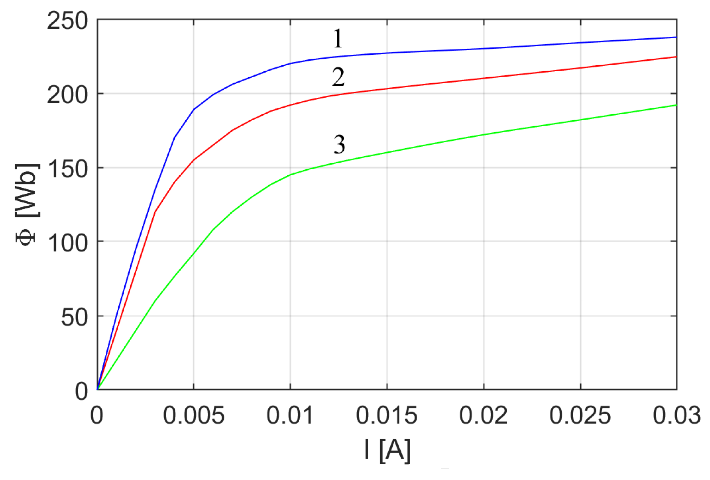
Considering the inductive voltage transformers applied, an important feature contributing to the possibility of inducing the ferroresonance phenomenon is the magnetization characteristic of the units. For this purpose, the characteristic defined as in number 2 was implemented as the base waveform, which is illustrated in Figure 3.
The subject of the power grid analysis, a fragment of which is shown in Figure 1, is the occurrence of parallel ferroresonance. The transient initiation is a consequence of an earth fault in phase L1 of the overhead line in bay 1. The incident mapping in the EMTP/ATP program is realized by closing the W9 circuit breaker. As a result of a disturbance, the W1 switch of the indicated bay is opened. The parameters of the operations cited, and the elements used to conduct the computer simulation, are presented in Table 2.
According to the theory, the ferroresonance phenomenon arises as a result of the correlation between the capacitive reactance of the power system XC and the inductive reactance of the voltage transformer reduced to the primary winding :
where:
The sum of inductive reactance of the voltage transformer present in the formula:
where XRL_1 is the reactance of the primary winding, is the reactance of the secondary winding reduced to the primary side,
is the load reactance of the measuring secondary winding reduced to the primary side, and is the core magnetization reactance.
The phenomenon of ferroresonance is extremely difficult to mathematically analyze. This is due to the nature of its initiation for different n- components of the Fourier series frequencies, where the fundamental frequency is fn and as presented in Formulas (2) and (3). The easiest way is to point to the idea of the phenomenon itself.
The cases of two-phase with the ground, two-phase and three-phase in the context of ferroresonance initiation in the considered power grid model (Figure 1) were also analyzed.
4. Simulation Results
4.1. Base Model Simulation Results
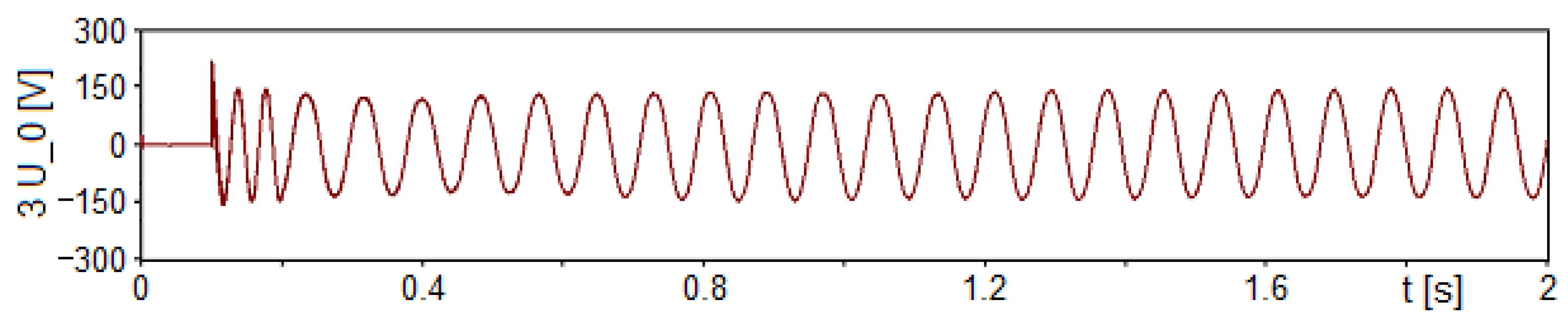
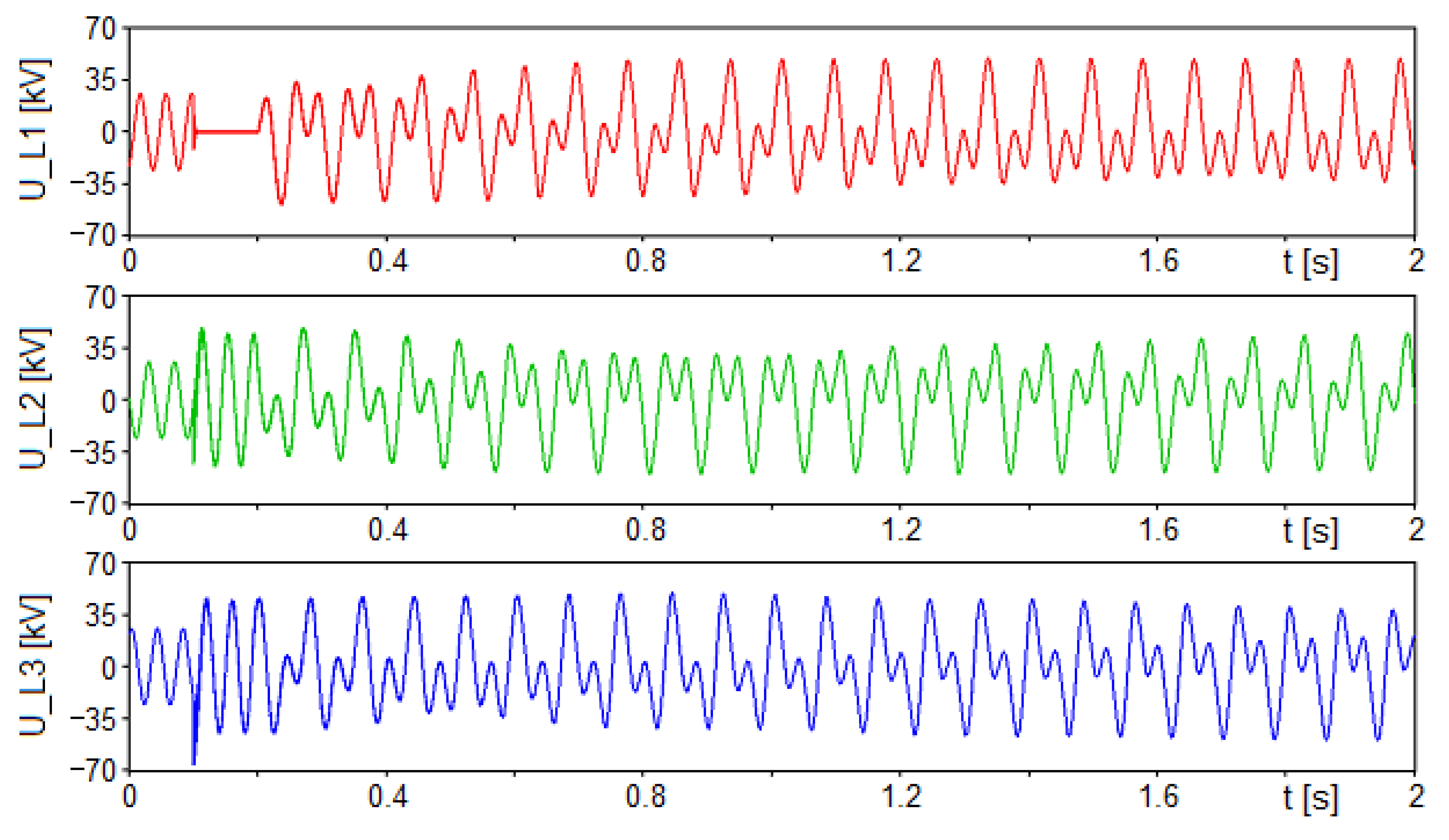
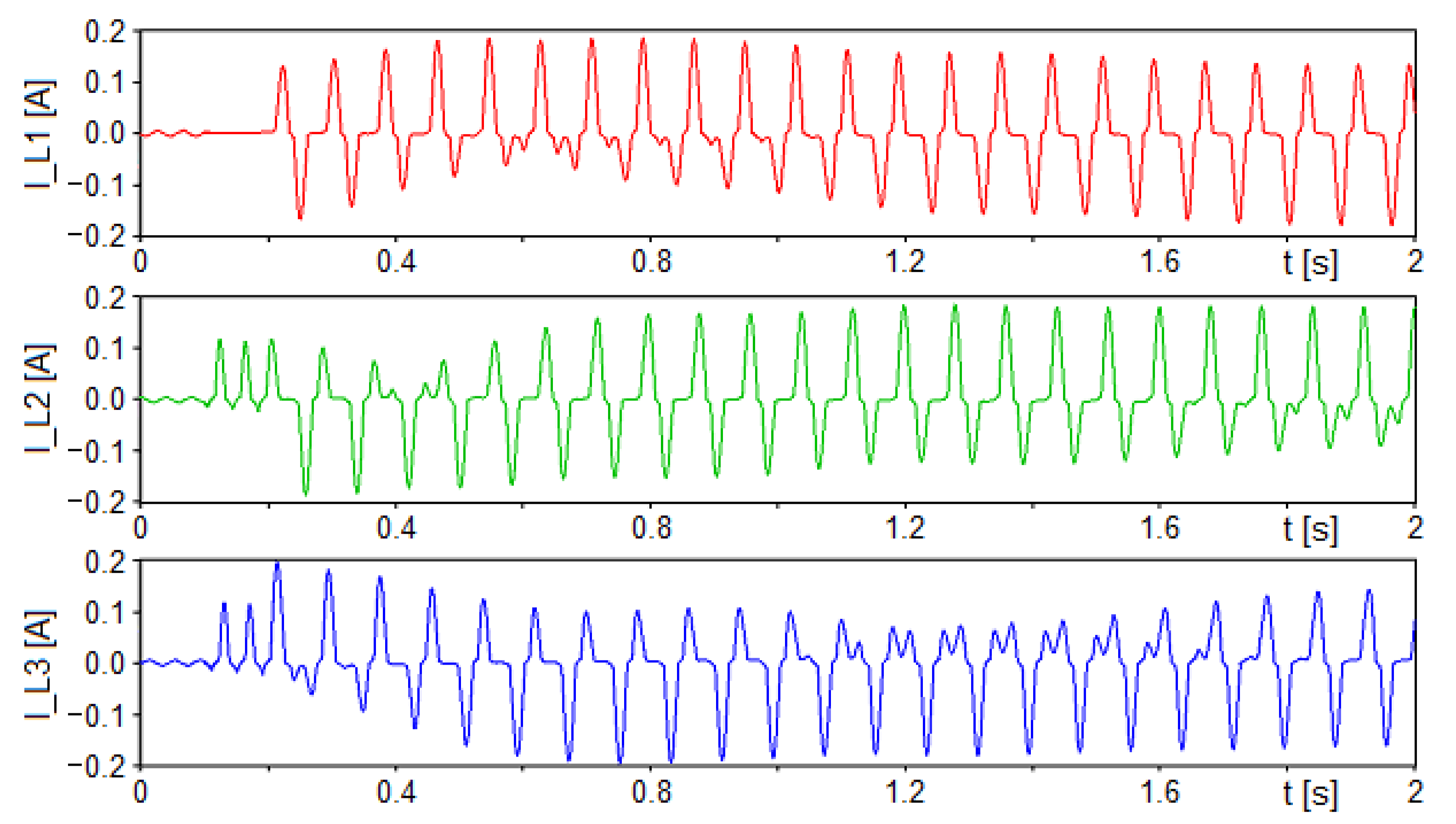
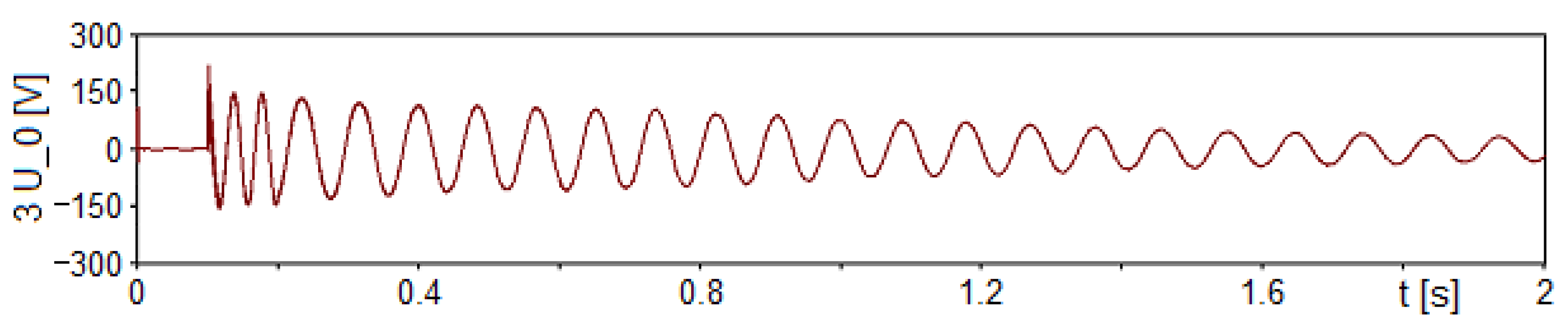
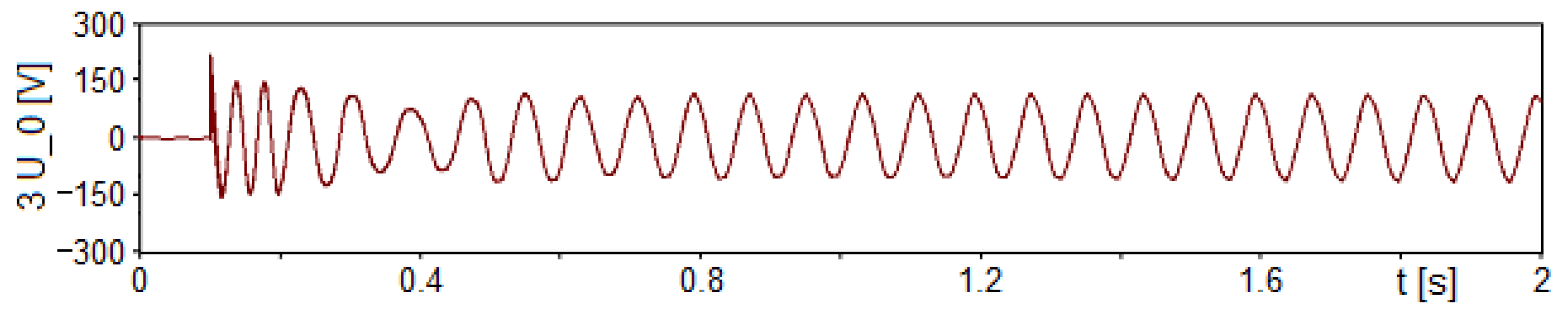
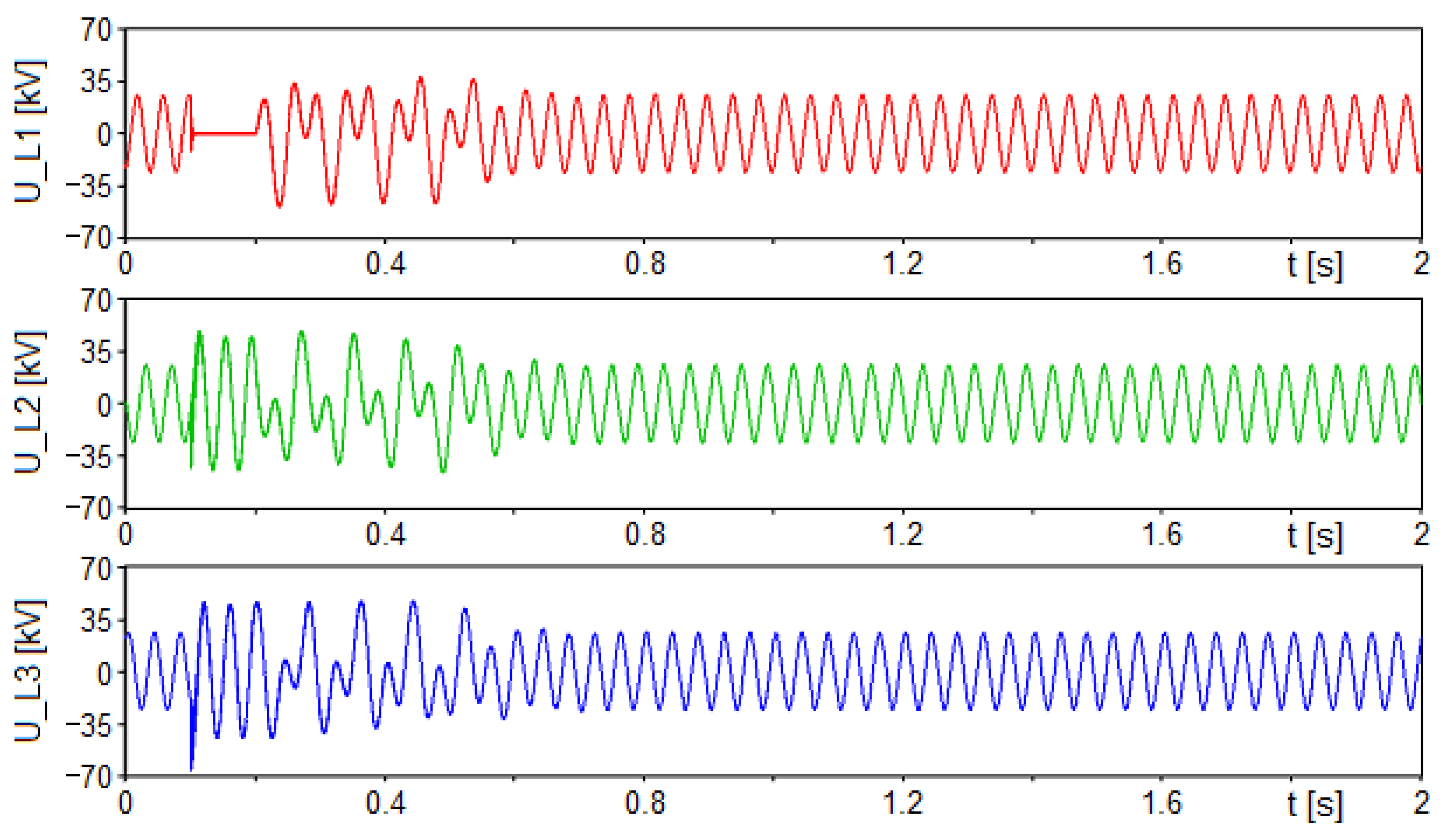
The waveforms representing the excitation of the ferroresonance phenomenon as a result of the earth fault (initiation of the short circuit–closing the W9 circuit breaker after 0.1 s, removing the disturbance—opening the W1 circuit breaker after 0.2 s) in the structure of the power grid, in the model shown in Figure 1, are shown in Figure 4, Figure 5 and Figure 6. The graphs were obtained for measurements carried out on the R_OT resistor in the case of zero-sequence voltage (Figure 4) and on the page terminal primary voltage transformers with respect to the phase voltages (Figure 5) and currents (Figure 6). The idea of using the R_OT resistor with a resistance of 1 MΩ is to create a circuit that allows the measurement of voltage, the structure of which corresponds to an open triangle system.
Based on the enclosed characteristics, it was noticed that the system maintains symmetry before the disturbance. The lack of zero-sequence voltage and the mutual correlation of voltage and current waveforms confirms this aspect. As a result of the disturbance, the trajectory is deformed, causing the appearance of the zero-sequence voltage and the voltage drop in the L1 phase to the zero value. In the L2 and L3 phases, the voltage increases to the interphase level. Similarly, for the current waveforms, which disappear in the short-circuited phase and increase in the remaining (non-grounded) phases. Opening the W1 switch in field 1 causes excitation of permanent, undamped ferroresonance. The presence of the ferroresonance phenomenon is evidenced by the presence of characteristic currents and phase voltages. This situation is accompanied by a large increase in currents on the primary side of voltage transformers. Their excessive value and long duration of occurrence can be very dangerous for the structure of power devices. However, the relationship between the waveform of the voltage at open delta terminals of the delta transformer (Figure 4) and the phase voltages of the transformers on the primary side (Figure 5) is worth emphasizing. This is the state of the network at the pre-fault conditions. After about 0.1 s, a disturbance appears, which represents the beginning of the phenomenon diagnosed based on the data in Figure 4. This translates into deformation of all three phase voltages (Figure 5), which lose their sinusoidal character with an amplitude of 24.5 kV, which in turn corresponds to the phase voltage amplitude of 30 kV (phase-to-phase voltage), precisely . All phase voltages reach peak values of up to 50 kV.
Based on the results presented in Figure 6, the currents do not reach the values that threaten the correct operation of the network, and their course is of secondary importance when it comes to assessing the ferroresonance phenomenon itself.
The analysis of other types of short circuits did not show the occurrence of the ferro-resonance phenomenon in the considered model of the power grid.
4.2. Results of Simulation of Models Taking into Account Ferroresonance Suppression Methods
The availability of forms of minimizing the ferroresonance phenomenon contributes to the possibility of their application in practical solutions. Therefore, at this stage, an essential element is to check all methods in terms of their effectiveness in a situation where nonlinear oscillations occur. The analysis concerns not only the comparison of the indicated methods with each other but also individual concepts depending on the properties of the elements contributing to the elimination of the ferroresonance phenomenon.
It was assumed that these effects would be candidates for assessment:
- Duration of the phenomenon. In this case, the lack of suppression of the phenomenon or suppression to a small extent destroys the very idea. Regardless of the amplitude of the phase voltages in the network, ferroresonance causes their distortion, increases the RMS value, and creates possible undesirable effects caused by higher harmonics.
- The second factor is the value of the voltage oscillation in the first resonance phase, Vmax.
4.2.1. Application of Anti-Ferroresonance Transformers
The first method of eliminating nonlinear vibrations is the use of anti-ferroresonance transformers. The idea behind the approach indicated is based on the materials used to build the cores. In this case, the use of sheets with poorer magnetic properties has a legitimate application. Materials with a more significant loss should also be emphasized. This solution contributes to the effective dissipation of energy in the core present during the ferroresonance phenomenon. A different meaning is given to the use of low-loss sheets, which negatively affect damping of the nonlinear oscillations that arise. The comparisons of the magnetization characteristics of voltage transformers, the cores of which are made of sheets with different losses, are shown in Figure 3.
The theoretical confirmation of the idea of the described solution are Formulas (5) and (6). The magnetic flux Φ depends on the magnetic induction vector and the surface vector as evidenced by Formula (5).
Magnetic induction is described by the magnetic permeability of the material μ, vacuum μ0, and the intensity of the magnetic field vector . According to Formula (6), the magnetic permeability of the material μ is a characteristic feature of a given material and thus of the described idea in terms of changing the inductive reactance X′μ (Formula (4)).
The implementation of the solution is related to the change in the magnetization characteristics of power devices implemented in the elements L_μ1, L_μ2, and L_μ3 (Figure 1). The influence of changing the parameters of the resistance and leakage inductance of voltage transformers was also analyzed in terms of the ferroresonance phenomenon.
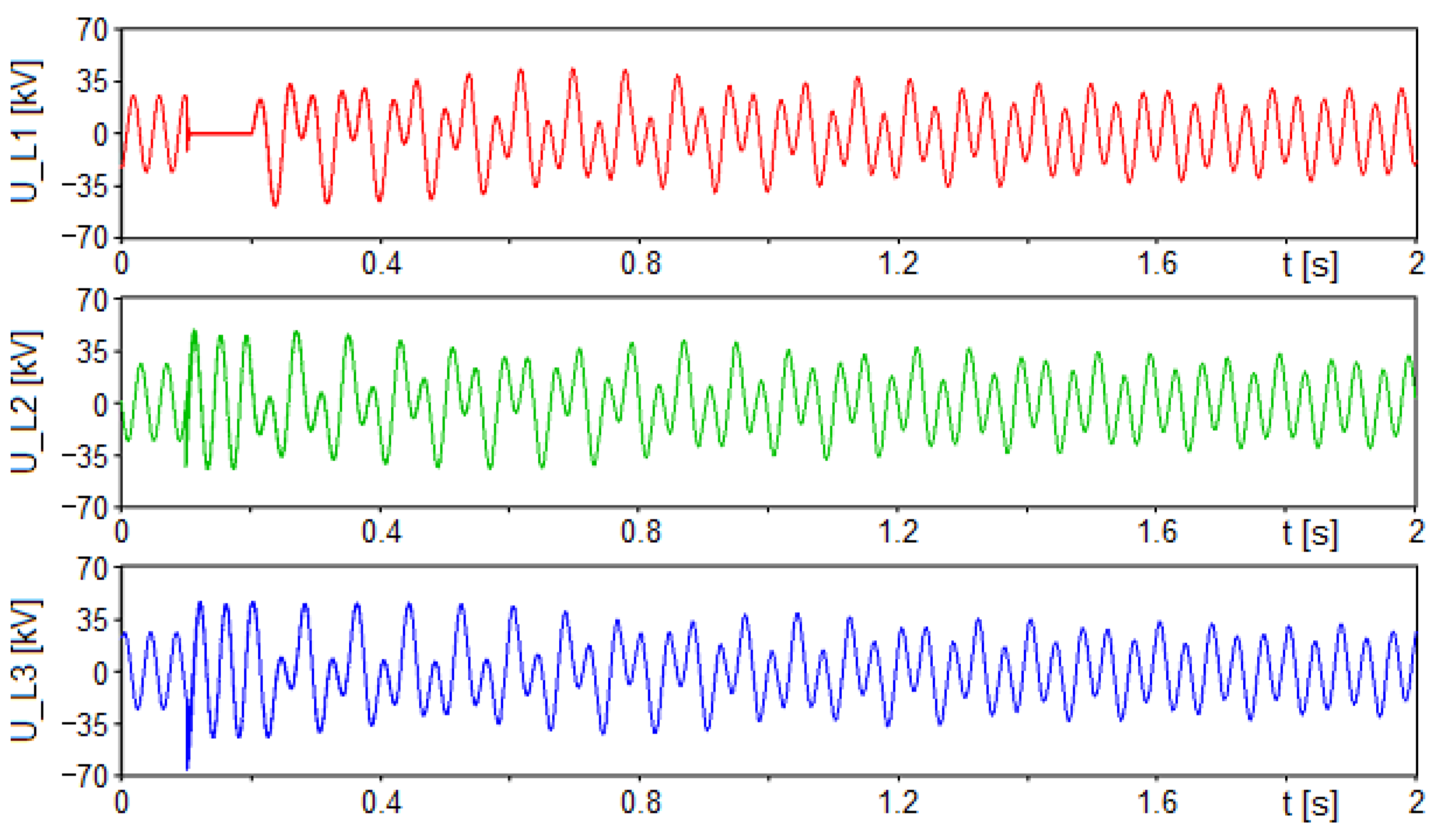
Voltage transformers with worse magnetic properties have magnetization characteristics defined by number 3 (Figure 3). Further analysis includes the change in the current characteristic defined by course number 2 to route number 3. Furthermore, as a result of the transformation, zero-sequence voltage and phase voltage graphs were obtained, which are presented in Figure 7 and Figure 8.
Based on the waveforms attached, several important conclusions can be drawn. First, the methods used to solve the problem of ferroresonant oscillations are fully effective. This is evidenced by the gradually subsiding vibrations of phase voltages and currents. However, their suppression period is relatively long, which is well illustrated by the characteristic of the zero-sequence voltage. As a confirmation of the outlined aspect, it should be noted that after 1.9 s from the disturbance occurrence, the voltage in the open delta circuit reaches about 32 V. This value is lower than the level determined immediately after opening the W1 switch in field 1, but it is still significant. Thus, despite the conclusion stated, it is not decisive regarding the effectiveness of the method presented.
The aspect indicating much worse attenuation properties of voltage transformers with cores made of sheets of lower loss was also analyzed. For this purpose, the magnetization characteristics of power devices determined by waveform 2 (Figure 3) were replaced by trajectory 1. The graphs indicated in Figure 9 and Figure 10 show the effect of the changes introduced.
The characteristics obtained clearly indicate the lack of effectiveness of the applied method for the case under consideration. The resulting disturbance is accompanied by ferroresonance excitation, the vibrations of which are permanent in phase voltages and currents. Failure to minimize the resulting oscillations may have negative effects on the design of voltage transformers, emphasizing their thermal and mechanical damage.
When analyzing the impact of changing the remaining voltage transformer parameters in the power grid model (Figure 1), it can be noticed that ferroresonance does not occur only when the R_Fe resistance value is decreased or when the primary side parameters are increased. The efficiency is related to the mentioned aspect of energy dissipation in the core.
4.2.2. Switching on the Damping Resistor in the Open Delta Circuit
One of the primary methods of eliminating ferroresonance is to connect a damping resistor in the open triangle circuit. The idea behind the role of minimization based on the solution mentioned above is to increase the damping factor (by loading the circuit and introducing resistance losses). The effectiveness of the method depends, among other things, on the time of component activation. The variety of solutions means that the resistor can be permanently connected to the additional winding, or it can be connected during transient states. Another significant parameter concerns the size of the applied resistance. This value is difficult to determine accurately. The only solution is to determine the minimum value of the resistance R_OTD that will ensure permissible changes in the temperature of the winding during the phenomenon.
The data contained in Formula (7) determine the rated voltage of the secondary winding connected in open delta configuration U2dn and the rated thermal load of this winding Pe (the apparent power that can be delivered to the winding without exceeding the temperature rise limit [24]).
The system’s structure in the EMTP/ATP program implementing the indicated solution is based on adding a series-connected resistor R_OTD with switch W10 to the open triangle winding, which is located parallel to the resistor R_OT. The diagram shown in Figure 1 was used as the base model.
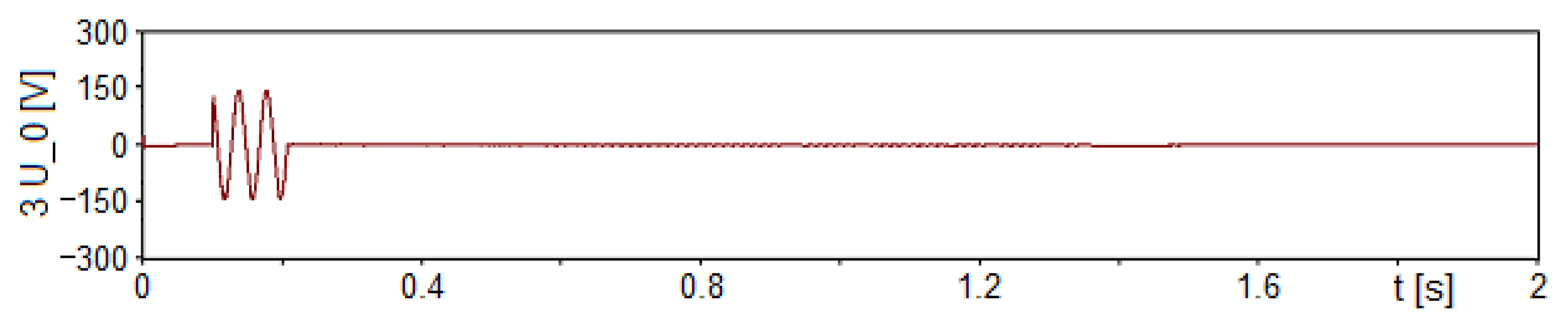
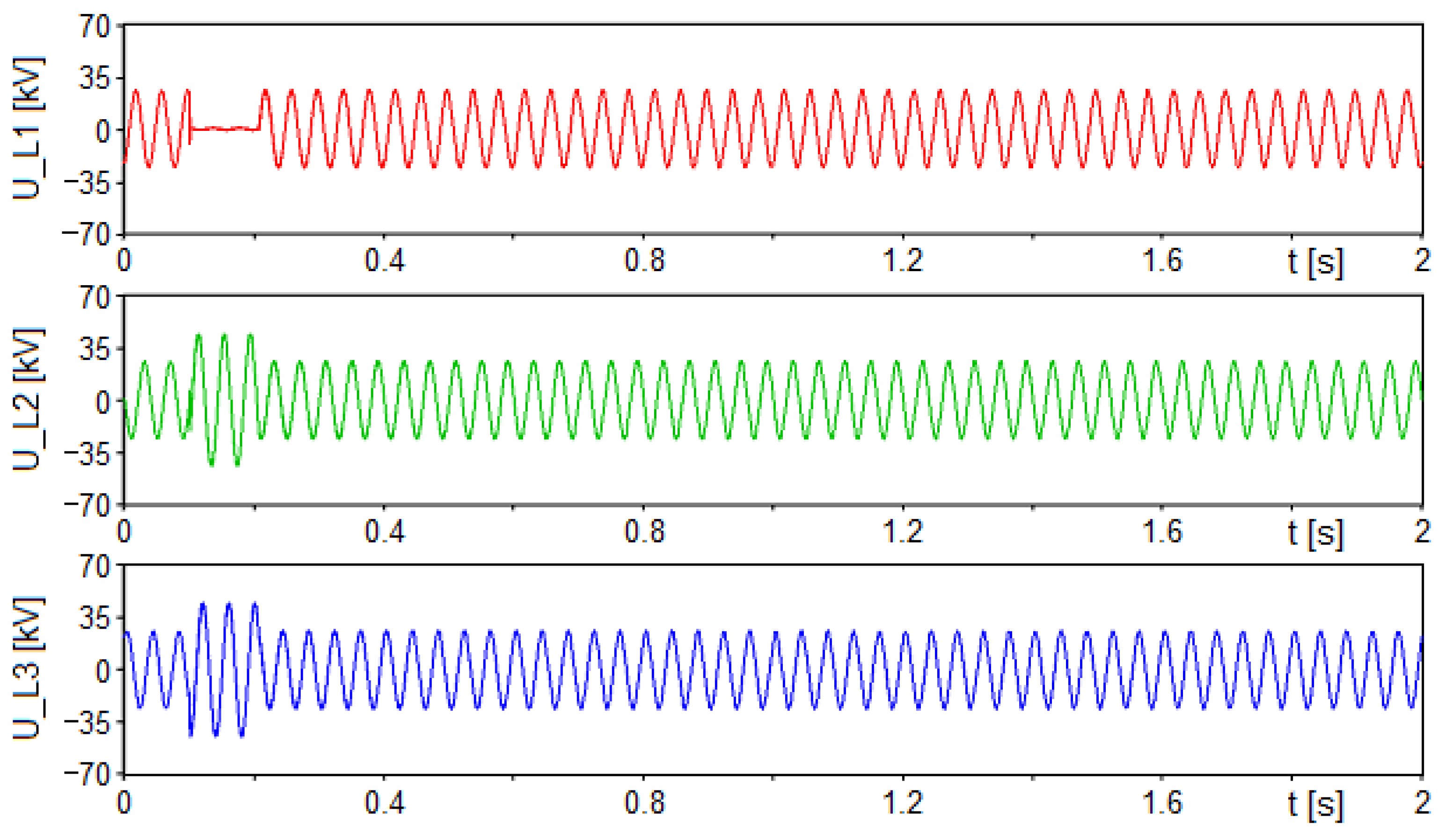
For the purpose of computer simulation of the system, it becomes necessary to define the parameters of the connected components. In this case, the value of the R_OTD resistor was set at 10 Ω, and the closing time of the W10 switch was set to 0.5 s from the moment of starting the simulation. For this structure, the voltage waveforms in the open delta circuit and the phase voltages on the primary side of the voltage transformers were obtained, as shown in Figure 11 and Figure 12.
According to the characteristics presented, all the phase voltage and current waveforms are established after connecting the damping resistor, causing the system to be restored to the state preceding the disturbance process. The time taken to reach the equilibrium is short because it is about 0.2 s for the case analyzed, indicating the moment of closing the W10 circuit breaker as a reference point. On this basis, the method presented should be classified as an effective method of elimination of the ferroresonance phenomenon.
Turning on the resistor first causes the resonance phenomenon to disappear in about 0.5 s. Second, after the same period, the phase voltages reach a sinusoidal steady state.
In line with the indication of the influence of the resistance value on the process of damping of nonlinear oscillations, this specificity was also taken account of in the considerations. To this end, the size of the R_OTD resistor was increased to 25 Ω while the closing time of the circuit breaker W10 was maintained. Figure 13 and Figure 14 show the courses of relevant parameters that take into account the modification introduced.
Based on the characteristics indicated, it can be seen that along with the increase in the resistance of the damping resistor, the damping time of nonlinear vibrations increases. For the case under consideration, it is about 0.4 s, which is an increase of 0.2 s compared to the previous solution. In an extreme situation, the tendency to increase the resistance may lead to the ineffectiveness of ferroresonance elimination. This also determines the issue wherein the selection of the damping resistor is a process necessary to ensure the correct operation of the system.
4.2.3. Grounding through the Transformer Star Point Resistor
The ferroresonance phenomenon can be minimized by grounding the transformer star point resistor. The basis of this method is forcing the zero-sequence current to flow. The effectiveness of the concept is related to the lower voltage increase in the disturbance state in relation to the structure working with an isolated point, and in the consequences of the minimalization of additional magnetic fluxes Φ in the voltage transformers, which thankfully does not cause excitation of ferroresonant oscillations. The correct operation of the system is related to the appropriate selection of the resistor. The process of determining the appropriate resistance level is complicated. However, there are methods that allow an indication of the optimal size of an element, which is confirmed in [32].
where Un is the nominal voltage of the power grid and IPN is the rated earth fault current.
Because power grids, to a large extent, operate with an isolated neutral point, the solution involves the use of an earthing transformer Tr_U 30/0.4 kV attached to the busbars, which provides power to the auxiliary needs of the power substation. This structure was also used to analyze this concept in the EMTP/ATP (Figure 1), which was obtained with the W11 circuit breaker closed.
Grounding through the transformer star point resistor determines the resistance value for the purpose of computer simulation. Therefore, the value of 50 Ω was assumed as the resistance R_PN, which results in the waveforms shown in Figure 15 and Figure 16.
Based on the described characteristics, it has been noticed that the ferroresonance phenomenon does not occur in the system earthed through the resistor. The result of the earth fault is manifested in the appearance of the voltage zero-sequence, which diminishes almost to zero after opening the circuit breaker W1 in bay 1. At the same time, only the period in which the fault condition occurs has an influence on the phase voltage waveforms. The departure of the currents from the classical outlines for the time after the elimination of the disturbance indicates that the voltage transformers are in a deep saturation state.
The aspect related to the selection of the resistor has been included in the consideration by simulating the system while indicating a different value of the resistor. Therefore, a second experiment was carried out with the assumption of resistance R_PN = 100 Ω.
The characteristics for R_PN = 100 Ω are almost identical to the trajectories resulting from the use of the R_PN = 50 Ω resistor. Slight differences in values occur for the duration of the fault state. This indicates the effectiveness in the elimination of ferroresonance in both cases considered. However, the resistor selection process should not be ignored since its correct determination allows for the appropriate limitation of transient overvoltages to values that are safe for the insulation of power system components.
4.2.4. Connecting the To-Ground Capacity
An analysis was also carried out to attach additional to-ground capacity to the busbars in order to detune the circuit from ferroresonant vibrations. The use of additional overhead lines, and in particular cable lines, can significantly contribute to the detuning of the system from nonlinear oscillations. The concept that lies behind the effectiveness of the solution presented is to change the to-ground capacity XC of the power grid. The simulation results showed that this is not a sufficiently effective form of ferroresonance damping. Furthermore, the time needed to dampen the oscillation entirely is quite long.
5. Discussion
Each of the methods described contributes to a greater or smaller extent to the elimination of the ferroresonance phenomenon. Nevertheless, an important feature to pay attention to during the analysis is the power grid system created by the ferroresonance elimination method. This aspect is particularly important for the selection of power system protections. In particular, the connection of the resistor R_OTD to the open delta windings and the earthing through the resistor R_PN of the power grid must be kept in mind. Particular attention should be paid to earth-fault protection, among other things. By far the largest earth fault overvoltages occur in an isolated system (and thus for the method involving the attachment of a resistor in an open-delta system) and small ones in a network earthed through a resistor. At the same time, the different nature of network operation translates into the need for different types of earth fault protection. In an isolated system, directional reactive or directional susceptance protections can be successfully used. However, these types of protection cannot be implemented in a network earthed through a resistor. Conversely, in a network earthed through a resistor, it is recommended to use directional active power protection or non-directional conductance protection (these protections cannot be used in an isolated network). The most recommended and current protection in both systems is the zero-voltage protection. A different aspect is the shock hazard for the types of mains considered related to ferroresonance elimination methods. The risk is significantly higher for a network earthed by a resistor than for an isolated system. At the same time, this translates into requirements for substation earthing resistance which are greater for a resistor earthed network than for an isolated system.
In view of the above, the choice of the elimination of ferroresonance brings with it the need to analyze many aspects affecting the correct operation of the electricity system. This forms the basis for another separate analysis of the topic.
6. Conclusions
As a result of the implementation of the elimination of the ferroresonance phenomenon, it may be concluded that there are many methods available with varying degrees of complexity and difficulties in implementing them into practical solutions. Furthermore, the wide range of damping methods also affects the effectiveness and course of the minimization process (presented in Section 4).
Among the methods of limiting the ferroresonance phenomenon analyzed and considered, two of them were seen to be effective (Section 4.2.2 and Section 4.2.3). It should be emphasized that both are characterized by similar values of phase voltages on the primary side of the transformer in the resonant state. None of the values of the additionally added resistors considered have an impact on the peak voltage levels. However, both the activation of the damping resistor in the open delta circuit (Figure 13 and Figure 14) and the grounding through the transformer star point resistor (Figure 15 and Figure 16) affect the attenuation and ferroresonance decay in less than 1 second. Therefore, the second method seems to be more effective in this respect.
One of the simplest methods of minimizing nonlinear vibrations is the use of anti-ferroresonance transformers (Section 4.2.1). However, the current trend of reducing dimensions, and in particular the dependence of the implementation of this technology on manufacturers, significantly limits the practical use of the method.
The solutions that use one or more damping resistors are the most effective in suppressing ferroresonance, which is confirmed by the simulations and literature. The use of a resistor in the open triangle circuit should be particularly emphasized. This concept has many more significant advantages over the location of resistors in the measurement windings. This is related to the proper efficiency, simpler implementation, and maintenance of the required measurement accuracy of the indicated method. Current solutions are largely based on a product that uses the active resistance variation of a resistor connected in an open delta. The concept proposed in this article is based on a constant resistance value and presents a different approach to the defined problem. The resistor is only connected with the switch when the fault occurs. With such a solution, the open delta secondary winding is not additionally loaded during all of the power grid operation, which is used in the available solutions (despite the very high resistance).
The above considerations confirm that the ferroresonance phenomenon with the participation of voltage transformers is a highly negative state, and its correct elimination using an appropriate suppression method, using a resistor in the open triangle circuit, is necessary to maintain the correct operation of the entire power system. A separate issue is to select the value of the added resistances for a specific transformer and network in which the entire system is to operate.
The authors performed computer simulations in a simulation environment that considers electrical parameters with a high approximation; however, simulations in a physical environment may provide additional information on methods of limiting the ferroresonance phenomenon. Being aware of the importance of the analyzed aspects, it was decided to publish the obtained results, which may become the basis for further development works. The developed issues are important because they can contribute to the improvement of the operating conditions of the systems (damping and ferroresonance decay). The simulations carried out indicate the high potential of the solution, which, in the long term, requires costly laboratory tests and the creation of a physical model for simulation in the measurement environment. This type of research can be performed in a separate research and development project. After confirming the correct and safe operation of the proposed solutions on physical models, the project should be implemented in a real environment with the participation of an industrial partner interested in implementing the solution.
Author Contributions
Conceptualization, W.K., P.S. and M.M.; methodology, W.K., P.S. and M.M.; software, M.M.; validation, W.K. and P.S.; investigation, M.M. and W.K.; writing—original draft preparation, W.K., P.S. and M.M.; writing—review and editing, W.K., P.S. and M.M.; visualization, M.M.; supervision, W.K. and P.S. All authors have read and agreed to the published version of the manuscript.
Funding
This research received no external funding.
Conflicts of Interest
The authors declare no conflict of interest.
References
- Li, Z.H.; Wang, Y.; Wu, Z.T.; Li, Z.X. Research on Electronic Voltage Transformer for Big Data Background. Symmetry 2018, 10, 234. [Google Scholar] [CrossRef] [Green Version]
- Letizia, P.S.; Crotti, G.; Giordano, D.; Delle Femine, A.; Gallo, D.; Landi, C.; Luiso, M. Low Cost Procedure for Frequency Characterization of Voltage Instrument Transformers. In Proceedings of the 2019 IEEE International Instrumentation and Measurement Technology Conference, Auckland, New Zealand, 20–23 May 2019. [Google Scholar]
- Crotti, G.; D’Avanzo, G.; Giordano, D.; Letizia, P.S.; Luiso, M. Extended SINDICOMP: Characterizing MV Voltage Transformers with Sine Waves. Energies 2021, 14, 1715. [Google Scholar] [CrossRef]
- Irfan, M.; Ayub, N.; Althobiani, F.; Ali, Z.; Idrees, M.; Ullah, S.; Rahman, S.; Saeed Alwadie, A.; Ghonaim, S.M.; Abdushkour, H.; et al. Energy theft identification using AdaBoost Ensembler in the Smart Grids. CMC-Comput. Mater. Cont. 2022, 72, 2141–2158. [Google Scholar] [CrossRef]
- Valverde, V.; Mazón, A.J.; Zamora, I.; Buigues, G. Ferroresonance in Voltage Transformers: Analysis and Simulations. In Proceedings of the International Conference on Renewable Energies and Power Quality, Bilbao, Spain, 20–22 March 2013. [Google Scholar]
- Faifer, M.; Laurano, C.; Ottoboni, R.; Toscani, S.; Zanoni, M. Characterization of Voltage Instrument Transformers under Nonsinusoidal Conditions Based on the Best Linear Approximation. IEEE Trans. Instrum. Meas. 2018, 67, 2392–2400. [Google Scholar] [CrossRef]
- Cataliotti, A.; Cosentiono, V.; Crotti, G.; Delle Femine, A.; Di Cara, D.; Gallo, D.; Giordano, D.; Landi, C.; Luiso, M.; Modarres, M.; et al. Compensation of Nonlinearity of Voltage and Current Instrument Transformers. IEEE Trans. Instrum. Meas. 2018, 68, 1322–1332. [Google Scholar] [CrossRef]
- Toscani, S.; Faifer, M.; Ferrero, A.; Laurano, C.; Ottoboni, R.; Zanoni, M. Compensating Nonlinearities in Voltage Transformers for Enhanced Harmonic Measurements: The Simplified Volterra Approach. IEEE Trans. Power Deliv. 2020, 36, 362–370. [Google Scholar] [CrossRef]
- Radmanesh, H.; Rostami, M.; Khalilpour, J. Ferroresonance in Voltage Transformer Considering Linear and Nonlinear Core Losses Effect. Int. J. Comput. Electr. Eng. 2012, 4, 789–793. [Google Scholar] [CrossRef]
- Jałmużny, W. Analysis of the properties of HV voltage transformers in abnormal operating conditions with particular consideration of ferroresonance oscillations. Zesz. Naukowe. Rozpr. Nauk./Politech. Łódzka 2013, 454, 1–185. [Google Scholar]
- Kpomahou, Y.; Miwadinou, C.; Hinvi, L. Mathematical modelling and parametric resonances of a nonlinear RLC series circuit. Int. J. Nonlinear Dyn. Cont. 2018, 1, 133–153. [Google Scholar] [CrossRef]
- Miličević, K.; Vinko, D.; Emin, Z. Identifying ferroresonance initiation for a range of initial conditions and parameters. Nonlinear Dyn. 2011, 66, 755–762. [Google Scholar] [CrossRef]
- Kochanowicz, K.; Nowak, W.; Tarko, R. Modeling and analysis of the ferroresonance phenomena in the electrical grid. Zesz. Nauk. Wydziału Elektrotechniki I Autom. Politech. Gdańskiej 2017, 57, 51–54. [Google Scholar]
- Liu, J.; Lu, X.; Wang, Y.; Wei, D.; Tang, J. Discriminate Method of Power Frequency Ferroresonance in System with Non-Effectively Earthed Neutral of Three-Phase Enclosed GIS. In Proceedings of the 2018 China International Conference on Electricity Distribution (CICED), Tianjin, China, 17–19 September 2018; pp. 801–805. [Google Scholar]
- Boutora, S.; Bentarzi, H.; Ouadi, A. Ferroresonance avoidance by distributed resources reconfiguration in islanded power grid. In Proceedings of the 9th WSEAS International Conference on Circuits, Systems, Electronics, Control & Signal Processing, Athens, Greece, 29–31 December 2010. [Google Scholar]
- Dugan, R.C. Examples of ferroresonance in distribution. In Proceedings of the 2003 IEEE Power Engineering Society General Meeting, Toronto, ON, Canada, 13–17 July2003; Volume 2, pp. 1213–1215. [Google Scholar]
- Cazacu, E.; Ioniţă, V.; Petrescu, L. An efficient method for investigating the ferroresonance of single-phase iron core devices. In Proceedings of the 10th International Symposium on Advanced Topics in Electrical Engineering, Bucharest, Romania, 23–25 March 2017. [Google Scholar]
- Barbisio, E.; Bottauscio, O.; Chiampi, M.; Crotti, G.; Giordano, D. Parameters Affecting Ferroresonance in LCR Electric Circuits. IEEE Trans. Magn. 2008, 44, 870–873. [Google Scholar] [CrossRef]
- Stosur, M.; Piasecki, W.; Florkowski, M.; Fulczyk, M. ATP/EMTP Study and Ferroresonance Involving HV Inductive VT and Circuit Breaker Capacitance. Electr. Power Qual. Util. J. 2008, 14, 49–52. [Google Scholar]
- Majka, Ł. Applying a fractional coil model for power system ferroresonance analysis. Bull. Pol. Acad. Sci. Tech. Sci. 2018, 66, 467–474. [Google Scholar]
- Tokić, A.; Kasumović, M.; Demirović, D.; Turković, I. Ferroresonance in 35 kV isolated networks: Causes and mitigations. Electrotech. Rev. 2016, 85, 259–265. [Google Scholar]
- Valverde, V.; Mazón, A.J.; Buigues, G.; Zamora, I. Ferroresonance Suppression in Voltage Transformers. Przegląd Elektrotechniczny 2012, 88, 137–140. [Google Scholar]
- Majka, Ł.; Sowa, M. Ferromagnetic core coil hysteresis modeling using fraction derivatives. Nonlin. Dyn. 2020, 101, 775–793. [Google Scholar]
- Ferracci, P. Cahier Technique no 190: Ferroresonance; Group Schneider: Rueil-Malmaison, France, 1998. [Google Scholar]
- Majka, Ł.; Klimas, M. Diagnostic approach in assessment of a ferroresonant circuit. Electr. Eng. 2019, 101, 149–164. [Google Scholar] [CrossRef] [Green Version]
- Poornima, S.; Sugumaran, C.P. Identification of ferroresonance phenomena using wavelet transforms. In Proceedings of the 2016 International Conference on Control, Instrumentation, Communication and Computational Technologies, Kumaracoil, India, 16–17 December 2016. [Google Scholar]
- Boutora, S.; Bentarzi, H. Ferroresonance Study Using False Trip Root Cause Analysis. Energy Proc. 2019, 162, 306–314. [Google Scholar] [CrossRef]
- Cazacu, E.; Petrescu, L.; Ioniţă, V. Ferroresonance modes determination of single-phase toroidal transformers. In Proceedings of the 15th International Conference on Electrical Machines, Drives and Power Systems, Sofia, Bulgaria, 1–3 June 2017. [Google Scholar]
- Rezaei-Zare, A.; Etemadi, A.H.; Iravani, R. Challenges of Power Converter Operation and Control under Ferroresonance Conditions. IEEE Trans. Power Deliv. 2017, 32, 2380–2388. [Google Scholar] [CrossRef]
- Poornima, S.; Sathyanandan, L.; Sugumaran, C.P. Ferroresonance Mitigation in an Inductive Voltage Transformer Using Memristor Emulator. In Proceedings of the 2019 International Conference on High Voltage Engineering and Technology, Hyderabad, India, 7–8 February 2019. [Google Scholar]
- Rezaei, S. Intelligent overcurrent protection during ferroresonance in smart distribution grid. In Proceedings of the 2019 IEEE International Conference on Environment and Electrical Engineering and 2019 IEEE Industrial and Commercial Power Systems Europe, Genova, Italy, 11–14 June 2019. [Google Scholar]
- Hoppel, W.; Lorenc, J. Wpływ impedancji transformatora uziemiającego na wielkości ziemnozwarciowe w sieci z punktem neutralnym uziemionym przez rezystor. Wiadomości Elektrotechniczne 2008, 7, 33–37. [Google Scholar]
Figure 1.
Model of the power network analyzed in the EMTP/ATP program, in which the ferroresonance phenomenon occurs.
Figure 1.
Model of the power network analyzed in the EMTP/ATP program, in which the ferroresonance phenomenon occurs.

Figure 2.
Model of single-phase voltage transformer for phase L1 made in EMTP/ATP software.

Figure 3.
Magnetization characteristics of voltage transformers, the cores of which are made of sheets (1) with the lowest loss, (2) with intermediate loss, and (3) with the highest loss.
Figure 3.
Magnetization characteristics of voltage transformers, the cores of which are made of sheets (1) with the lowest loss, (2) with intermediate loss, and (3) with the highest loss.

Figure 4.
Waveform of the voltage at open delta terminals of the delta transformer.

Figure 5.
Waveforms of phase voltages on the primary side of voltage transformers under ferroresonant oscillation conditions.
Figure 5.
Waveforms of phase voltages on the primary side of voltage transformers under ferroresonant oscillation conditions.

Figure 6.
Current waveforms on the primary side of voltage transformers under ferroresonant oscillation conditions.
Figure 6.
Current waveforms on the primary side of voltage transformers under ferroresonant oscillation conditions.

Figure 7.
The voltage waveform in the open delta circuit resulting from changing the magnetization characteristics of the voltage transformers from waves 2 to 3.
Figure 7.
The voltage waveform in the open delta circuit resulting from changing the magnetization characteristics of the voltage transformers from waves 2 to 3.

Figure 8.
Phase voltage waveforms on the primary side of voltage transformers as a result of changing their magnetization characteristics from 2 to 3.
Figure 8.
Phase voltage waveforms on the primary side of voltage transformers as a result of changing their magnetization characteristics from 2 to 3.

Figure 9.
The voltage waveform in the open delta circuit as a result of changing the magnetization characteristics of the voltage transformers from waveform 2 to 1.
Figure 9.
The voltage waveform in the open delta circuit as a result of changing the magnetization characteristics of the voltage transformers from waveform 2 to 1.

Figure 10.
Phase voltage waveforms on the primary side of voltage transformers as a result of changing their magnetization characteristics from 2 to 1.
Figure 10.
Phase voltage waveforms on the primary side of voltage transformers as a result of changing their magnetization characteristics from 2 to 1.

Figure 11.
The voltage waveform in the open delta circuit, including the attenuation resistor R_OTD = 10 Ω in the additional winding system.
Figure 11.
The voltage waveform in the open delta circuit, including the attenuation resistor R_OTD = 10 Ω in the additional winding system.

Figure 12.
Waveforms of phase voltages on the primary side of voltage transformers, including the attenuation resistor R_OTD = 10 Ω in the additional winding system.
Figure 12.
Waveforms of phase voltages on the primary side of voltage transformers, including the attenuation resistor R_OTD = 10 Ω in the additional winding system.

Figure 13.
The voltage waveform in the open delta circuit, taking into account the damping resistor R_OTD = 25 Ω in the additional winding system.
Figure 13.
The voltage waveform in the open delta circuit, taking into account the damping resistor R_OTD = 25 Ω in the additional winding system.

Figure 14.
Waveforms of phase voltages on the primary side of voltage transformers, including the attenuation resistor R_OTD = 25 Ω in the additional winding system.
Figure 14.
Waveforms of phase voltages on the primary side of voltage transformers, including the attenuation resistor R_OTD = 25 Ω in the additional winding system.

Figure 15.
The voltage waveform in the open delta circuit, taking into account the presence of an earthing transformer connected to earth through a resistor R_PN = 50 Ω.
Figure 15.
The voltage waveform in the open delta circuit, taking into account the presence of an earthing transformer connected to earth through a resistor R_PN = 50 Ω.

Figure 16.
Waveforms of phase voltages on the primary side of voltage transformers, taking into account the presence of an earthing transformer connected to earth through a resistor R_PN = 50 Ω.
Figure 16.
Waveforms of phase voltages on the primary side of voltage transformers, taking into account the presence of an earthing transformer connected to earth through a resistor R_PN = 50 Ω.


Table 1.
Parameters of the power grid model analyzed.
| Name | Parameter | Value |
|---|---|---|
| Power system—G_1 | Rated voltage—Un | 110 kV |
| Energy transformer—Tr_1 | Rated power—Sn Upper voltage—UGN Low voltage—UDN | 63 MVA 115 kV 31.5 kV |
| Inductive voltage transformers | Rated primary voltage—U1n Rated secondary voltage—U2n Rated open delta voltage—U2dn | kV V V |
| Cable lines | Types of cables | 3 × XRUHAKXS 1 × 240 mm2 3 × XRUHAKXS 1 × 120 mm2 |
| Overhead lines | Types of lines | AFL-6-120 mm2 AFL-6-95 mm2 |
Table 2.
Parameters of elements and operations of the power grid model contributing to the excitation of nonlinear oscillations.
Table 2.
Parameters of elements and operations of the power grid model contributing to the excitation of nonlinear oscillations.
| Element | Parameter | Value |
|---|---|---|
| Resistance R_p | Transition resistance at the fault location | 1 |
| Switch W9 | Switch closing time | 0.1 s |
| Switch W1 | Switch opening time | 0.2 s |
Publisher’s Note: MDPI stays neutral with regard to jurisdictional claims in published maps and institutional affiliations. |
© 2022 by the authors. Licensee MDPI, Basel, Switzerland. This article is an open access article distributed under the terms and conditions of the Creative Commons Attribution (CC BY) license (https://creativecommons.org/licenses/by/4.0/).
Share and Cite
MDPI and ACS Style
Kraszewski, W.; Syrek, P.; Mitoraj, M. Methods of Ferroresonance Mitigation in Voltage Transformers in a 30 kV Power Supply Network. Energies 2022, 15, 9516. https://doi.org/10.3390/en15249516
AMA Style
Kraszewski W, Syrek P, Mitoraj M. Methods of Ferroresonance Mitigation in Voltage Transformers in a 30 kV Power Supply Network. Energies. 2022; 15(24):9516. https://doi.org/10.3390/en15249516
Chicago/Turabian StyleKraszewski, Wojciech, Przemysław Syrek, and Mateusz Mitoraj. 2022. "Methods of Ferroresonance Mitigation in Voltage Transformers in a 30 kV Power Supply Network" Energies 15, no. 24: 9516. https://doi.org/10.3390/en15249516
Note that from the first issue of 2016, this journal uses article numbers instead of page numbers. See further details here.