Experimental and Numerical Investigation of Extinguishing Effectiveness of Inert-Gas Agents in a Leaky Enclosure


Department of Safety, Chemical and Biomedical Laboratory Sciences, Faculty of Engineering and Sciences, Western Norway University of Applied Sciences, 5528 Haugesund, Norway
*
Author to whom correspondence should be addressed.
Energies 2022, 15(12), 4323; https://doi.org/10.3390/en15124323
Submission received: 17 May 2022
/
Revised: 8 June 2022
/
Accepted: 11 June 2022
/
Published: 13 June 2022
(This article belongs to the Section I2: Energy and Combustion Science)
Abstract
:Gas-fire-suppression systems are currently applied to some specific buildings in Norway, as sprinkler systems may not provide sufficient protection in some cases. The application of inert-gas-fire-suppression systems for hazard class 6 buildings needs further intensive validation by experimental and numerical study. Due to the presence of cracks and ventilation systems, it becomes doubtful whether inert-gas agents can extinguish a deep-seated fire located in a leaky enclosure. In this study, tests and numerical simulations were both conducted to investigate the extinguishing effectiveness of inert-gas agents for a closet fire in a leaky apartment. The results show that the location of cracks plays a nonnegligible role in determining the oxygen level in the leaky apartment. The tests and simulations demonstrated that the gas-fire-suppression system successfully extinguished the closet fire even if the activation of the gas-fire-suppression system was postponed or the path available for the inert-gas agent to reach the fire source was narrowed. However, the sprinkler system failed to achieve this. The experimental data also demonstrated that the calculation method proposed in our previous work can be used to estimate the oxygen level in a leaky enclosure.
1. Introduction
A fire caused three casualties at Sveio Elderly Home in Norway in 2007 [1]. The fire started at the back of a refrigerator in a storage room in the midnight. Soon after the optical smoke detector went off, the employee on duty identified the fire source location. When the door of the storage room was opened, a backdraft occurred. The fire could not be suppressed anymore using the available extinguisher; only an automatic fire-suppression system would have been able to control/extinguish the fire at this stage. The Sveio fire led to a change in the Norwegian fire safety regulations. In 2010, the installation of an automatic fire-suppression system became compulsory in hazard class 6 buildings [2]. These are structures designed for overnight stay where residents may not be able to evacuate without help. In most cases, a sprinkler system is installed. Nevertheless, in the past decade, fires also caused casualties at sprinkler-system care homes in Norway. In 2018, a fire started on a table next to a sitting lady who could not evacuate without assistance at Berge Gård elderly home [3]. Although the fire spread was suppressed by the sprinkler, the fire still released a large amount of smoke which caused the death of the lady. In 2016, another fire took the life of a lady aged 85 at a sprinkler-system Care Home in Biri [4]. The above accidents illustrate that high risks are present if a fire is well established in a high fuel-loaded room (e.g., Sveio fire) and the resident is dependent on assistance to egress. Therefore, the use of a personal safe gas-suppression system to extinguish a fire at an early stage has been studied. In addition, in some areas in Norway, freshwater supply required for the sprinkler system is very demanding due to climate and or geographical circumstances (e.g., on small islands). Gas-fire-suppression systems, as an alternative to sprinkler systems, have attracted great interest recently in Norway as gas agents can penetrate air-permeable enclosures to provide extinguishment where water may not be able to reach. Until now, the research has focused on finding appropriate gas agents, investigating the extinguishing mechanism, and analyzing the toxicity of gas agents.
In the past three decades, the gas agents used in fire-suppression systems have undergone a transition from halon agents to clean agents [5,6]. The clean agents fall into two broad categories: (1) halocarbon compounds and (2) inert gases and mixtures. Halocarbon clean agents produce some decomposition products (primary HF), which pose great risks to personnel [6]. Inert-gas agents are regarded as genuine “clean agents”, mainly because they present absolutely zero risks to the environment, short- or long-term. Inert-gas agents mainly include nitrogen, argon, and blends of these, which do not produce any decomposition products in fires. The most common inert-gas agents available on the market are nitrogen (IG-100), argon (IG-01), nitrogen + argon (IG-55), and nitrogen + argon + CO2 (IG-541) [6,7]. The inert gas-suppression systems are suitable for situations where sensitive equipment needs to be protected or the safety of people is concerned. To date, some critical structures, e.g., archives, power generation, satellite control systems, and museums, have installed gas-fire-suppression systems in Norway [8].
The extinguishing mechanism of inert-gas agents is to reduce the oxygen concentration to a threshold level, below which the heat generated by reactions is not enough to keep it going. The oxygen threshold level is slightly affected by the properties of inert-gas agents and ambient temperature. A fire is supposed to be extinguished if the oxygen volume fraction is below the threshold value, which is in the range 10.3 % to 13.9 %, according to the experiments [9,10].
In occupied areas, the health concern of gas-fire-suppression systems has to do with a hypoxic effect due to oxygen depletion. As learned from experiments in humans, low oxygen hypoxia represents usually a minor deleterious effect unless oxygen concentration decreases below 12% [11]. However, severe effects and incapacitation might occur if human are exposed to a 10% oxygen atmosphere. Experiments conducted by Lambertsen [12] show that the presence of CO2 in the atmosphere can promote a breathing feature, which is called the “CO2 effect”. Laursen [13] suggests the benefit of the “CO2 effect” is that it can increase the exposure time up to 30 min even for COPD patients (chronic obstructive pulmonary disease) in a 10–12.5% O2 and 3.5–4% CO2 atmosphere. The agent IG-541 adds approximately 8% CO2 as a component to maximize the exposure time of occupants.
The above discussion shows that the oxygen level is a crucial factor concerning extinguishing effectiveness and human safety. Normally, an oxygen volume fraction in the range of 12–13% is proposed as the design level for gas-fire-suppression systems [14]. Intensive research has been conducted on the discharge equipment and the selection of gas agents regardless of the configuration of the protected enclosures. Little efforts have been devoted to investigating if the design oxygen level can be achieved when considering real fire scenarios. In practice, to achieve a design oxygen level in an enclosure, several issues arise:
- The gas discharge usually generates an overpressure effect in a hermetical enclosure. However, most buildings have ventilation systems and leaks of some sort, e.g., cracks under doors or windows, which can prevent a rapid pressure build up during the discharge period. A question is whether a design oxygen level can be achieved when the effects of ventilation and leakage are taken into account.
- The inert-gas agents are normally heavier than the ambient air and are discharged at a very low temperature. It is doubtful whether the inert-gas agents can reach every corner of an enclosure in a short period. It is necessary to investigate whether inert-gas agents can extinguish a deep-seated fire which is located in a narrow corner space in the upper layer of an enclosure.
To answer these questions, a series of tests and computer simulations have been carried out. Before the introduction of the tests and simulations, the relation between the quantity of gas agents and the oxygen level was discussed first.
2. Oxygen Level and Agent Quantity
Gas-fire-suppression systems are supposed to discharge a specific quantity of gas agents into an enclosure to achieve a design oxygen level within a specific period. To achieve the design oxygen level, the discharge quantity of gas agents needs to be evaluated with a consideration of leakage and ventilation effects.
The simplest approach assumes that the leakage only occurs at the end of a discharge period. Hence the agent–air mixture that has escaped from an enclosure has the same species composition as the mixture that remains in the enclosure at the end of the discharge period. The agent fraction can be easily calculated from the air initially in the enclosure and the gas agents added. The quantity of a gas agent (w) required to achieve a design volume fraction of the gas agent (C) is determined by [6]:
where w is the agent quantity (kg), is the enclosure volume (m3), and is the density of the gas agent (m3/kg) at ambient temperature.
In practice, the agent-air mixture is pressed out of an enclosure from the beginning to the end of the discharge. A flooding factor is used to account for the leakage from the enclosure during the discharge period [6,7]. To achieve the design volume fraction of the gas agent (C), the quantity of a gas agent is calculated by:
The volume fraction of the gas agent, instead of the oxygen fraction, is used in Equations (1) and (2). The fraction of the gas agent can be easily converted into the fraction of oxygen if needed.
A general formula to express the relation between the discharge quantity of gas agents and the oxygen level is proposed in our previous work [15]. It is assumed that air and inert-gas agents are uniformly distributed at any time in an enclosure. represents the discharge mass flow rate of the gas agent (kg/s) and represents the mass flow rate of the mixture (kg/s) that has escaped from the enclosure. and are functions of time. The mass fraction of oxygen at time t is given by:
where is the mass fraction of oxygen initially in the enclosure, e.g., for fresh air. is the total mass of mixture in the enclosure at time and can be expressed as:
The discharge quantity of the gas agent at time t is:
If the exit flow rate equals the discharge flow rate, that is, = , the quantity of the gas agent () is simplified as a function of the mass fraction of oxygen:
Equations (3)–(5) give general expressions to estimate the oxygen level from the discharged quantity. However, it may not be solved analytically if the exit rate E and the discharge rate R are not linear functions. These equations were proposed in our previous work [15] to calculate the quantity of inert gas needed for a protected enclosure and to estimate the oxygen level during the discharge period. However, these equations were developed without any experimental validation. In a later discussion, Equation (6) is used to estimate the oxygen level and the calculation is compared with the experimental data.
3. Set Up of Tests and Simulations
The tests and simulations were conducted in a dummy apartment to evaluate whether the agent IG-541 could be used in a high-security clinic for psychiatric care in Trondheim, Norway.
3.1. Tests
An apartment was built with plaster boards according to the rooms in the psychiatric care in Trondheim [16]. As no measures were taken to seal the enclosure, cracks were present between the joints of two plaster boards or between the plaster boards and the floor. The height of the apartment was 3.0 m and its layout is shown in Figure 1. The total volume of the apartment was approximately 46 m3. The door between the main room and the bathroom was open, while the entrance door was closed. A big crack was observed at the bottom of the entrance door. A window was installed at 0.9 m above the floor and was closed during the tests. An INERGEN® system [17] from the company Fire Eater was used to protect the apartment. The filling process of the gas agent could be observed through the window. An INERGEN nozzle was mounted on the top right of the right wall. Two sprinkler nozzles (Raven 5.6 k institutional, Tyco) were mounted on the ceiling of the main room according to the standard NS-EN 12,845 fixed fire-suppression systems [18]. The sprinkler nozzle was triggered automatically if the sprinkler reached its rated temperature of 74 °C [19]. A thermocouple bar was placed next to the closet (marked as location P) to measure the temperature at the height from 1.3 m to 3.0 m. A CO detector and a smoke detector were mounted on the ceiling. An oxygen instrument was placed at 0.95 m above the floor. The ventilation system, consisting of an inlet, an outlet, and a pressure relief valve, was installed on the ceiling to clean the gas residual produced in the previous test. The ventilation rates were 80 m3/hour and 108 m3/hour for the inlet fan and outlet fan, respectively. The locations of these equipment items can be found in Figure 1. The ambient temperature was relatively low, approximately 6–11 °C, during the tests.
IG-541 is one of the most common inert-gas agents used in occupied areas. It consists of 52% N2, 40% Ar, and 8% CO2. The small fraction of CO2 can increase the exposure time significantly in the atmosphere with 10–12.5% O2 due to the benefit of the “CO2 effect”. Therefore, IG-541 was selected as the gas agent in the tests. The molecular mass of IG-541 is 34.0 and the specific volume S () at standard pressure may be approximated by Formula (6):
where and . The reverse of specific volume is the density of IG-541. One cylinder of agent IG-541 was used for the gas test. The cylinder was 80 litres and was stored with IG-541 at a pressure of 300 bar at 20 °C. According to the INERGEN Management Tool (IMT) calculation report, 95% of IG-541 was released through the low noise nozzle within 120 s [17].
Test 1 was designed to measure the oxygen fraction if the gas agent IG-541 was discharged into the apartment. To avoid smoke obscuration, this test was conducted without a fire introduced. The oxygen fraction was measured by the oxygen instrument at 0.95 m above the floor at the corner between the main room and the bathroom (see Figure 1 for the location). When the gas discharge was in operation, the inlet fan stopped before the test and the outlet fan stopped exhausting the agent-air mixture after a 60 s operation.
Test 2 was designed to investigate the extinguishing effectiveness of inert-gas agents and the sprinkler separately. A burning match ignited a wood crib placed under the clothes hanging in the closet (Figure 2b). The clothes were made of pure cotton or polyester/cotton blends. The weight of the clothes was 377 g. The closet was made of pine panels. To create a deep-seated fire, the smoke detector was mounted far away from the closet to postpone the detection of fires. Figure 2c shows the fire at 115 s. In Test 2 (I), one cylinder of IG-541 was discharged into the apartment to extinguish the fire. The INERGEN system was manually activated after 30 s of the alarm of the smoke detector. At that time, the temperature next to the closet at a height of 3.0 m (marked as location P3) was around 130 °C. When the gas discharge was in operation, the inlet fan stopped 5 s before the discharge and the outlet fan stopped after a 60 s operation. In Test 2 (II), the sprinkler nozzles were activated automatically to suppress the fire. The ventilation system kept running during the sprinkler operation period. If the fire was not extinguished before the completion of the discharge, manual extinguishment was adopted. The tests are summarised in Table 1.
3.2. Simulations
The tests were numerically modelled using FDS [20], which is a computational fluid dynamics (CFD) model of fire-driven fluid flow. The CFD model has been validated to be able to reproduce the fire development and gas movement in many practical studies [21,22,23]. The dimension of the enclosure built by FDS was the same as that shown in Figure 1. The discharge rate of IG-541 was estimated using IMT calculation [17]. IMT calculated the discharge rate according to the set up of a gas extinguishing system, e.g., the storage pressure of the cylinder, the manifold with attached orifice, the pipe system, and the nozzle. The calculated discharge rate is shown in Figure 3.
For the simulations without a fire introduced, the discharge started at 15 s, which was the same as the start time in Test 1. The inlet stopped before the discharge and the outlet vent exhausted the air-agent mixture at a rate of 0.03 m3/s for the first 60 s. For the simulations with fires introduced, the discharge started when the temperature at location P3 was 130 °C if no special mention was made. As the ventilation procedure should be determined before the FDS simulations, it was impossible to adjust the operation time according to the fire development. In the simulations, the inlet ran for the first 60 s and the outlet stopped after another 60 s, which was close to the operation time in Test 2 (I).
For the simulations with fires introduced, a closet was placed in the corner, as shown in Figure 1. The thickness of the closet panels was 0.05 m, and the interior space was 0.6 × 0.6 × 1.8 m3. As the properties of the closet panels were not measured in the tests, the combustion properties of the pine panels measured from [24] were used as input data for the closet panels. For the clothes hanging in the closet, combustion properties of 40/60 polyester blend fabrics shown in [25] were used as input data. The closet back panel facing the entrance door consisted of two surface layers that were made of fabric and pine. The corresponding thicknesses of the two layers were 0.005 m and 0.05 m, respectively. The input data is list in Table 2. A particle ignitor was placed at 5 cm away from the back panel and 5 cm above the middle horizontal panel to ignite the fabric layer. The ignition temperature of cellulose cotton (210 °C) was used in FDS as the auto-ignition temperature [26]. The simple flame extinction model [27] in FDS was applied to gauge whether or not a combustion was sustainable. The extinction model assumes that combustion reactions are suppressed if the temperature is below the auto-ignition temperature or if the heat released from a combustion process is not sufficient to raise the fuel-air-product-mixture temperature above a critical flame temperature. The default value of 1327 °C in FDS was used as the critical flame temperature in the simulations.
As the cracks between the joints of two plaster boards or the connections between the plaster board and the floor are extremely small, these cracks cannot be modeled directly in FDS. The entire apartment was set as a pressure zone with a leakage area of 0.01 m2. An intensive air-agent mixture was observed exiting from the bottom of the entrance door during the discharge periods. To represent the leakage through this crack, the bottom of the entrance door was modelled as a localized leak surface with a leakage area of 0.05 m2.
To investigate the leakage effect on the gas discharge effectiveness, the crack was first built up according to the Test 1 scenario (T1_bottom). Then the crack location was changed to the top or the vertical side of the entrance door (T1_top and T1_side). In the simulation series T2, the extinguishing effectiveness was investigated by varying the activation time of the gas-suppression system. First the closet fire was simulated to predict the fire development if no gas agents was discharged (T2_fire). Then the simulation case T2_fire+agent was set up according to the scenario of Test 2 (I). In the simulation case T2_delay, the discharge time was postponed to the time when the temperature at location P3 reached 200 °C. As the study concerned the extinguishing effectiveness of the inert-gas agent for a fire located in a narrow space, the closet was designed to be partially closed with a vertical side opening of 0.1 m in the simulation series T3. The simulation cases in this study are summarized in Table 3.
The mesh sensitive analysis for the same apartment with a discharge of IG-541 has been conducted in the paper [15]. In this paper, the mesh size, varying from 0.18 m to 0.075 m, was used to discretize the computational domain. The temperature and mass fraction beneath the ceiling of the main room predicted from the four mesh solutions were compared. Convergence was obtained when the mesh solution was no more than 0.1 m. Thus, the mesh solution of 0.05 m was adequate to produce mesh-independent simulation results. Therefore, the following discussion is based on the results from simulations with 0.05 m mesh solution.
4. Results
4.1. Oxygen Level
Test 1 and simulation series T1 were carried out to measure the oxygen level when inert-gas agents were discharged into the apartment. The inert-gas agent expanded when it was released from a high-pressure cylinder into an open atmosphere. The expansion resulted in a loss of internal energy, which lead to a very low discharge temperature. In Test 1, IG-541 agent cooled down the surrounding air, in combination with the very high humidity (84–92% Rh) originally in the enclosure, causing intensive condensation of humidity in the air. The temperature near the nozzle was measured to be approximately −16 °C. The air–agent mixture was observed to descend towards the floor. Intensive condensation was also observed exiting from the crack at the bottom of the entrance door. The discharge generated a maximum pressure of 8 Pa which lasted for a few seconds. The maximum pressure can be ignored compared to the resistance value of 500 Pa of typical building materials [7].
The oxygen volume fraction was measured at 0.95 m above the floor at the corner between the main room and the bathroom in Test 1 (Figure 4a). The oxygen volume fraction decreased continuously during the discharge period and reached a minimum value of 12.3% at 242 s (Figure 4b). When the discharge stopped, the oxygen fraction increased in a very slow manner and reached 14.5% at 900 s. The increase in the oxygen fraction might be caused by the fresh air entering the apartment through the cracks. Figure 4 also shows the oxygen fractions predicted from the simulation case T1_bottom and calculated from the discharge mass flow (see Figure 3) using Equation (6). The oxygen fractions are in very good agreement with each other, which means that simulation can reproduce the gas filling process reasonably and Equation (6) can provide quite precise estimations on the oxygen fraction during the discharge period.
As the air-agent mixture was observed descending to the floor, the gas distribution along the height needs to be investigated. The oxygen fractions at 2.5 m, 0.95 m, and 0.25 m above the floor at the corner were predicted in the simulation case T1_bottom. Figure 5 shows that the oxygen fraction increases with the increasing height. The minimum oxygen fraction was 15.3% at 2.5 m above the floor, which was much higher than the design level. The oxygen fractions at the middle and lower layers, however, were very close to each other and reached the design level at the end of the discharge time. Therefore, it can be concluded that the oxygen fraction was distributed unevenly within the apartment. The oxygen fraction was much higher in the upper layer than that in the middle and lower layers. During the post-discharge time, the oxygen fraction increased 7% at 2.5 m and 17% at 0.95 and 0.25 m. This means that more fresh air entered the apartment through the bottom crack in this case.
As the pressure and oxygen distribution were not even in the enclosure, the crack location plays an important role in determining the oxygen fraction. In the simulation series T1, three crack locations were considered. Figure 6 shows the average oxygen fraction within the enclosure predicted from the three simulations. The minimum of the average oxygen fraction is 13.3% for the case T1_bottom, which is a little higher than the design level. The average oxygen fraction decreased to a minimum value of 12.2% and stayed around that level during the post-discharge time for the case T1_top. For the case T1_side, the oxygen level was between the two levels of T1_bottom and T1_top. This demonstrates that less oxygen stays in the apartment if the crack is located at the top of the door.
To have a better view on the distribution of the air-agent mixture, the velocity profile at 60 s on the slice that crosses the entrance door for simulation case T2_bottom and T2_top is shown in Figure 7. At that time, the inert-gas agent was discharged into the enclosure at a relatively high mass flow rate. The cold agent kept descending towards the floor, resulting in a lower oxygen level in the lower layer. The pressure in the enclosure was slightly higher than the ambient pressure. The air-agent mixture was pressed out of the apartment through the entrance crack due to the pressure difference. When the crack was located at the bottom of the entrance door (T1_bottom), the flow velocity through the crack could reach nearly 1 m/s. For the case T1_top, there was a strong turbulence in the lower layer. The air-agent mixture was pressed out of the enclosure through the top crack at a velocity of around 0.5 m/s, which is much lower than that of T1_bottom. Figure 7 illustrates that less inert-gas agent is pressed out of the enclosure if the crack is at the top.
4.2. Fire Extinguishment
The simulation results of T1 show that the oxygen was not evenly distributed in the apartment. More oxygen stayed in the upper layer compared to the middle and lower layer. Therefore, the extinguishing effectiveness in the upper layer needs to be investigated.
In Test 2, the clothes hanging in the closet were ignited with a burning match. The fire was well established (see Figure 2c) before the activation of the extinguish systems. Table 4 lists the procedures of the two tests. In Test 2 (I), the closet fire was extinguished with IG-541 at round 220 s, which was 105 s after the activation time. In Test 2 (II), only the sprinkler nozzle closer to the closet (sprinkler nozzle 1 shown in Figure 1) released water droplets as the nearest one got warm enough to be activated. It was observed that water droplets could not reach the interior of the closet. At 363 s, the fire was extinguished manually. The tests show that the gas-suppression system can extinguish a deep-seated closet fire within the discharge time while the sprinkler systems failed to do that.
The simulation series T2 was set up according to Test 2. The scenario of simulation case T2_fire+agent is similar to Test 2 (I). To check if the simulation can reasonably reproduce the test, the temperatures at location P3 measured in Test 2 (I) and predicted from simulation case T2_fire+agent are given in Figure 8. The time axis for T2_fire+agent is the secondary (top) horizontal axis. The temperature predicted from T2_fire+agent increased at the start. However, the temperature measured from Test 2 (I) started to increase approximately 40 s later than that predicted from T2_fire+agent. The reason is that the test started before the ignition of the match. Moreover, it took some time for the burning match to ignite the wood crib and, in turn, to ignite the clothes in the test. Ignoring the misalignment of the start time, the trends of the two temperature lines match to each other very well. Therefore, it is reasonable to assume that the simulation can reproduce the phenomenon of the test.
In the simulation case T2_fire, the closet fire kept going as inert-gas agents were not discharged into the enclosure (Figure 9a). It was predicted that the oxygen fraction in the middle of the top closet decreased to 14% at 300 s (Figure 9b). The decrease in the oxygen fraction was due to the consumption of oxygen. Test 2_fire+agent was discharged IG-541 into the enclosure at 90 s. Compared with T2_fire, there were nearly no changes in heat release rate (HRR) in the first 20 s of the discharge period in the case T2_fire+agents. The reason was that the oxygen fraction near the closet was more than 18%, above which the oxygen fraction was still high enough to support the fire. When the oxygen fraction decreased to below 17%, the HRR started to decrease significantly. After a 120 s discharge period, the HRR was near zero. The oxygen fraction in the top closet decreased to 11% at that time, which was even lower than the design level. The reason was that combustion consumed some oxygen around the fire source.
To investigate whether the activation time of a gas-fire-suppression system affects the extinguishing effectiveness, T2_delay postponed the activation time to 188 s. At this time the temperature at location P3 was 200 °C. Figure 10 shows the HRR was predicted to reach near zero much earlier before the discharge completed. The reason is that the fire consumed lots of oxygen before the discharge started. An interesting phenomenon is that the HRR increased instead of decreased in the first 10 s of the discharge period in the case T2_delay. This may be explained by the fast injection of inert gas in the first few seconds. A large amount of gas was discharged into the apartment, resulting in a fast mixing of fuel and oxygen.
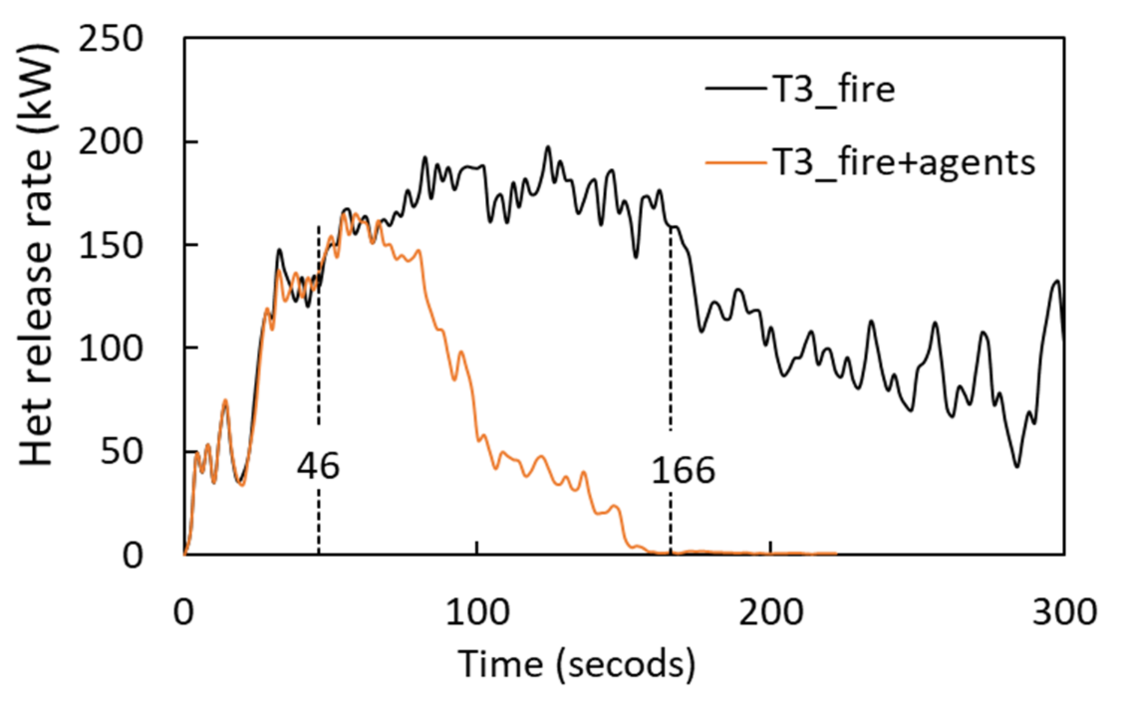
In Test 2, the closet was fully open, which provided a relatively wide path for the inert-gas agent to reach the fire source. Simulation series T3 narrowed the path available for the inert gas to flow into the closet by partially closing the closet. The opening was set to be 0.1 m wide on the vertical side. Figure 11 shows the HRR for the simulation series T3. The fire developed quite fast if the closet was partially closed. The temperature at location P3 reached 130 °C at 46 s and the inert gas was discharged into the enclosure. The HRR decreased to near zero at the end of the discharge for the case T3_fire+agents. This demonstrates that the inert-gas agent can extinguish a fire located in a narrow space in the upper layer.
5. Conclusions
This study is a part of the work investigating whether inert-gas-fire-suppression systems can meet the requirements in the regulations for automatic fire-suppression systems for hazard class 6 buildings. The calculation method proposed in [15] needed validation via experimental and numerical data as well. Tests and numerical simulations were conducted to measure the oxygen level and to extinguish a closet fire in a leaky apartment. The main conclusions are as follows:
- Tests, simulations, and calculation all demonstrated that the design oxygen level can be approximately achieved at the end of the discharge period, even taking leakage into account. However, the oxygen level increased slowly during the post-discharge time as fresh air could enter the enclosure through the cracks. The calculation method proposed in [15] was proved to be able to estimate the required quantity of gas agent in terms of protected volume.
- The oxygen fraction is not evenly distributed within an enclosure and more oxygen stays in the upper layer. Therefore, the crack location plays a nonnegligible role in determining the oxygen level. Less inert-gas agent is pressed out of the enclosure if cracks are located in the upper layer.
- The gas-fire-suppression system can extinguish a deep-seated closet fire in the enclosure, even if the fire is located in the upper layer and the activation time is postponed. Although the sprinkler system can control the fire spread, it failed to extinguish the fire.
The above demonstrates that the gas-fire-suppression systems are an alternative for fire protection of hazard class 6 buildings. To make the gas-fire-suppression systems more widely applicable, more research is required in further work. In this study, only small cracks were considered. If the windows or doors are open, the opening size would affect the flow of the agent-air mixture significantly. In addition, a persistent ignition source can lead to resurgence of the fire if fresh air can enter the enclosure through the cracks or openings.
Author Contributions
Conceptualization, X.H.; methodology, X.H. and A.K; software, X.H.; validation, X.H. and A.K.; formal analysis, X.H.; investigation X.H. and A.K.; resources, X.H. and A.K.; data curation, X.H. and A.K.; writing—original draft preparation, X.H.; writing—review and editing, X.H. and A.K.; visualization, X.H; project administration, X.H. and A.K. All authors have read and agreed to the published version of the manuscript.
Funding
This research is part of project “Building design for At-risk groups” funded by Western Norway University of Applied Sciences and the search council of Norway.
Acknowledgments
We are grateful to HH Fire Eater A.S. for providing INGERT gas agent.
Conflicts of Interest
The authors declare no conflict of interest.
References
- Direktoratet for Samfunnssikkerhet og Beredskap (DSB). Evaluering av Brann 9 Juni 2007 i Sveio Omsorgssenter; DSB: Tønsberg, Noway, 2007; ISBN 978-82-7768-117-7. [Google Scholar]
- DIBK. Regulations on Technical Requirements for Construction Works; Norwegian Building Authority: Oslo, Noway, 2017. [Google Scholar]
- Agderposten. Kvinne Alvorlig Skadd Etter Brann I Grimstad. Available online: https://www.agderposten.no/nyheter/kvinne-alvorlig-skadd-etter-brann-i-grimstad/ (accessed on 15 September 2018).
- OANO—Ohio Association of Nonprofit Organizations. Kvinne(85) Døde Som Følge av Røykutviking. Available online: https://www.oa.no/biri/brann/innlandet-politidistrikt/kvinne-85-dode-som-folge-av-roykutvikling/s/5-35-343945 (accessed on 5 November 2016).
- Grant, C.C. Halon design calculations. In SFPE Handbook of Fire Protection Engineering, 5th ed.; Hurley, M.J., Gottuk, D., Hall, J.R., Jr., Harada, K., Kuligowski, E., Puchovsky, M., Torero, J., Watts, J.M., Jr., Wieczorek, C., Eds.; SFPE: Gaithersburg, MD, USA, 2016; Chapter 43; pp. 1450–1482. [Google Scholar] [CrossRef]
- DiNenno, P.J.; Forssell, E.W. Clean agent total flooding fire extinguishing systems. In SFPE Handbook of Fire Protection Engineering, 5th ed.; Hurley, M.J., Gottuk, D., Hall, J.R., Jr., Harada, K., Kuligowski, E., Puchovsky, M., Torero, J., Watts, J.M., Jr., Wieczorek, C., Eds.; SFPE: Gaithersburg, MD, USA, 2016; Chapter 44; pp. 1483–1529. [Google Scholar] [CrossRef]
- IG 100-IG01-IG55-IG541; Bettati, Design Manual for Inert Gas System. Bettati Antincendio: Reggio Emilia, Italy, 2010.
- Kraaijeveld, A. Rapport Vedrørende Anvendelse av IG-541 som Alternative til Sprinkleranlegg; Western Norway University of Applied Sciences: Bergen, Norway, 2018. [Google Scholar]
- Beyler, C. Flammability limits of premixed and diffusion flames. In SFPE Handbook of Fire Protection Engineering, 5th ed.; Hurley, M.J., Gottuk, D., Hall, J.R., Jr., Harada, K., Kuligowski, E., Puchovsky, M., Torero, J., Watts, J.M., Jr., Wieczorek, C., Eds.; SFPE: Gaithersburg, MD, USA, 2016; Chapter 17; pp. 529–553. [Google Scholar] [CrossRef]
- Simmons, R.F.; Wolfhard, H.G. Some Limiting Oxygen Concentrations for Diffusion Flames in Air Diluted with Nitrogen. Combust. Flame 1957, 1, 155–161. [Google Scholar] [CrossRef]
- Purser, D.A. Combustion Txoicity. In SFPE Handbook of Fire Protection Engineering, 5th ed.; Hurley, M.J., Gottuk, D., Hall, J.R., Jr., Harada, K., Kuligowski, E., Puchovsky, M., Torero, J., Watts, J.M., Jr., Wieczorek, C., Eds.; SFPE: Gaithersburg, MD, USA, 2016; Chapter 62; pp. 2207–2307. [Google Scholar] [CrossRef]
- Lambertsen, C.J. Summary of Relations, Physiologic Factors and Fire Protection and Engineering Design; Report, 4-14-92; Environmental Biochemical Research Data Center (EBRDC), Institute of Environmental Medicine: Philadelphia, PA, USA; University of Pennsylvania: Philadelphia, PA, USA, 1994. [Google Scholar]
- Laursen, T. Fire protection for weak citizens. In Proceedings of the Nordic Fire and Safety Days, Copenhagen, Denmark, 20–21 August 2019; RISE Research Institutes of Sweden AB: Gothenburg, Sweden, 2019. [Google Scholar]
- ISO 14520-1; Gaseous Fire Extinguish Systems—Physical Properties and System Design, Part 1: General Requirements. International Standards Organization: Geneva, Switzerland, 2006.
- Hu, X.; Kraaijeveld, A.; Log, T. Numerical investigation of the required quantity of inert gas agents in fire suppression systems. Energies 2020, 13, 2536. [Google Scholar] [CrossRef]
- Kraaijeveld, A. Fire protection of at-risk groups by IG-541 and water based sprinklers: Full scale tests. In Proceedings of the Nordic Fire and Safety Days, Copenhagen, Denmark, 20–21 August 2019; RISE Research Institutes of Sweden AB: Gothenburg, Sweden, 2019. [Google Scholar]
- Fire Eater. Fire Eater Control Inert Ci Manual for UL Listed Extinguishing System; Fire Eater A/S: Hillerød, Denmark, 2013. [Google Scholar]
- Norge, S. NS-EN 12845: Faste Brannslokkesystemer-Automatiske Sprinklersystemer-Dimensjonering, Installering og Vedlikehold; Standard Norway: Oslo, Noway, 2015. [Google Scholar]
- TYCO. RAVEN 5.6K Institutional Sprinklers Pendent and Horizontal Sidewall Quick Response, Standard and Extended Coverage; Johnson Controls: Cork, Ireland, 2018. [Google Scholar]
- McGrattan, K.; Hostikka, S.; McDermott, R.; Floyd, J.; Weinschenk, C.; Overholt, K. Fire Dynamics Simulator User’s Guide, 6th ed.; NIST Special Publication; NIST: Gaithersburg, MD, USA, 2013. [Google Scholar] [CrossRef]
- McGrattan, K.; Hostikka, S.; McDermott, R.; Floyd, J.; Weinschenk, C.; Overholt, K. Fire Dynamics Simulator Technical Reference Guide Volume 1: Mathematical Model; National Institute of Standards and Technology (NIST) Special Publication 1018-3; NIST: Gaithersburg, MD, USA, 2021. [Google Scholar]
- Hu, X.; Jia, F.; Wang, Z.; Galea, E. Grouping methods for MPS soot transport model and its application in large-scale enclosure fires. Fire Saf. J. 2017, 9, 361–370. [Google Scholar] [CrossRef]
- Hu, X. Numerical study of the effects of ventilation velocity on peak heat release rate and the confinement velocity in large tunnel fires. Saf. Sci. 2021, 142, 105359. [Google Scholar] [CrossRef]
- Hejtmánek, P.; Ševčík, L.; Cábová, K. Input data of burning wood for CFD modelling using small-scale experiments. Civ. Eng. J. 2017, 4, 38. [Google Scholar] [CrossRef]
- Chen, Q.; Zhao, T. The thermal decomposition and heat release properties of the nylon/cotton, polyester/cotton and Nomex/cotton blend fabrics. Text. Res. J. 2016, 86, 1859–1868. [Google Scholar] [CrossRef]
- Hou, J. Distribution Curves for Interior Furnishings on CO2, CO, HCN, Soot and Heat of Combustion. Master’s Thesis, Department of Civil and Natural Resources Engineering, University of Canterbury, Christchurch, New Zealand, 2011. [Google Scholar]
- McGrattan, K.; Hostikka, S.; McDermott, R.; Floyd, J.; Weinschenk, C.; Overholt, K. Fire Dynamics Simulator Technical Reference Guide Volume 1: Mathematical Model, 6th ed.; NIST Special Publication 1018(1); NIST: Gaithersburg, MD, USA, 2013. [Google Scholar]
Figure 1.
Layout of the apartment (unit: mm).

Figure 2.
(a) The façade of the apartment; (b) fire load in the closet; (c) 115 s after ignition.

Figure 3.
Discharge mass flow (kg/s).

Figure 4.
(a) The location of the oxygen instrument; (b) the oxygen volume fraction at this location.
Figure 4.
(a) The location of the oxygen instrument; (b) the oxygen volume fraction at this location.

Figure 5.
Oxygen volume fraction at 2.5 m, 0.95 m, and 0.25 m above the floor at the corner between the main room and the bathroom.
Figure 5.
Oxygen volume fraction at 2.5 m, 0.95 m, and 0.25 m above the floor at the corner between the main room and the bathroom.

Figure 6.
Average oxygen volume fraction within the apartment for the simulation series T1.

Figure 7.
The velocity on the slice that crosses the entrance door after 60 s discharge for simulation case (a) T2_bottom and (b) T2_top.
Figure 7.
The velocity on the slice that crosses the entrance door after 60 s discharge for simulation case (a) T2_bottom and (b) T2_top.

Figure 8.
Temperature at location P3.

Figure 9.
(a) Heat release rate and (b) oxygen volume fraction in the center of the top closet for simulation cases T2_fire and T2_fire+agent.
Figure 9.
(a) Heat release rate and (b) oxygen volume fraction in the center of the top closet for simulation cases T2_fire and T2_fire+agent.

Figure 10.
Heat release rate for simulation T2_delay.

Figure 11.
Heat release rate for simulation series T3.


Table 1.
Summary of the tests.
| Case Index | Description | |
|---|---|---|
| Test 1 | Test 1 | One cylinder of IG-541 was discharged into the apartment. |
| Test 2 | Test 2 (I) | One cylinder of IG-541 was discharged to extinguish a closet fire |
| Test 2 (II) | Sprinkler was activated automatically to suppress a closet fire |
| Combustion Properties | Pine | Fabrics |
|---|---|---|
| Density (kg/m3) | 520 | 148 |
| Specific heat capacity (kJ/kg∙K) | 2.5 | 1.0 |
| Thermal conductivity (W/m∙K) | 0.2 | 0.1 |
| Reference temperature (°C) | 335 | 375 |
| Reaction intensity (s−1) | 0.00267 | 0.015 |
| Heating rate (K/min) | 5 | 10 |
| Heat of reaction (kJ/kg) | 1047 | 3000 |
| Heat of combustion (kJ/kg) | 11,410 | 14,000 |
Table 3.
Summary of the simulation cases.
| Case Index | Description | |
|---|---|---|
| T1 Discharge only | T1_bottom | A crack located at the bottom of the entrance door |
| T1_top | A crack located at the top (2 m) of the entrance door | |
| T1_side | A crack located at the vertical side of the entrance door | |
| T2 A closet fire | T2_fire | A closet fire without the discharge of inert-gas agents |
| T2_fire+agent | A closet fire with the discharge of inert-gas agents | |
| T2_delay | A closet fire with a delay activation of the gas extinguish system | |
| T3 The closet is partially closed | T3_fire | A fire in a partially closed closet without the discharge of inert-gas agents |
| T3_fire+agent | A fire in a partially closed closet with the discharge of inert-gas agents |
Table 4.
The procedures of Test 2.
| Test | Smoke Detection | Activation | Extinguishment | Discharge Completed |
|---|---|---|---|---|
| Test 2 (I)_IG-541 | 85 s | 115 s (manual) | 220 s | 235 s |
| Test 2 (II)_Sprinkler | 105 s | 125 s (auto) | 363 s (manual) | --- |
Publisher’s Note: MDPI stays neutral with regard to jurisdictional claims in published maps and institutional affiliations. |
© 2022 by the authors. Licensee MDPI, Basel, Switzerland. This article is an open access article distributed under the terms and conditions of the Creative Commons Attribution (CC BY) license (https://creativecommons.org/licenses/by/4.0/).
Share and Cite
MDPI and ACS Style
Hu, X.; Kraaijeveld, A. Experimental and Numerical Investigation of Extinguishing Effectiveness of Inert-Gas Agents in a Leaky Enclosure. Energies 2022, 15, 4323. https://doi.org/10.3390/en15124323
AMA Style
Hu X, Kraaijeveld A. Experimental and Numerical Investigation of Extinguishing Effectiveness of Inert-Gas Agents in a Leaky Enclosure. Energies. 2022; 15(12):4323. https://doi.org/10.3390/en15124323
Chicago/Turabian StyleHu, Xiaoqin, and Arjen Kraaijeveld. 2022. "Experimental and Numerical Investigation of Extinguishing Effectiveness of Inert-Gas Agents in a Leaky Enclosure" Energies 15, no. 12: 4323. https://doi.org/10.3390/en15124323
Note that from the first issue of 2016, this journal uses article numbers instead of page numbers. See further details here.