1. Introduction
Ice production is essential for many applications in the refrigeration industry, including energy storage, food and vaccine preservation, and freeze desalination. In rural areas, transportation, fishing boats, and many other usages, there are needs for more efficient and thermally driven ice makers due to the limited electricity sources [
1,
2]. In addition, the current commonly used devices to produce ice are based on vapor compression cycles. These devices are highly electricity-consuming and use environmentally harmful refrigerants (HFCs, HCFCs) that contribute to aggravating global warming crises [
3,
4,
5]. Adsorption refrigeration systems (ARSs) are considered environmentally friendly energy-saving systems that use low-quality thermal energy provided by solar or waste heat sources [
6,
7]. Furthermore, they can utilize natural refrigerants such as water and ethanol and require low maintenance efforts due to fewer moving parts. These ecological and practical merits make them the most attractive and feasible way to meet the new international environmental regulations for refrigeration systems to a great extent [
8,
9]. However, ARSs in principle work under thermal swings between adsorption and regeneration processes. The thermal response along with adsorption kinetics in adsorption beds play a critical role in determining the cyclic transient operation performance of the ARS. Therefore, enhancing both thermal and adsorption characteristics of the adsorbent materials represents an active research area that aims at boosting the effective use of ARSs in different applications. Many investigations have been devoted to developing adsorbent beds with higher thermal performance including the use of a metal foam structure to accommodate the adsorbent material [
10,
11,
12].
Metal-foam-based adsorbent beds have been proposed to enhance heat diffusion by conduction in the adsorbent domain via well-structured metal connectivity. This increases the effective thermal conductivity while providing high metal-to-adsorbent contact area and vapor permeability by foam cavities, and keeping good mechanical strength at higher foam thicknesses [
13,
14]. Mohammed et al. [
15] experimentally tested aluminum foam packed with silica gel particles on a small scale for adsorption cooling applications and reported effective thermal conductivity of 6 W∙m
−1∙K
−1 for the composite form. They developed a CFD model for the foam and silica gel domain and predicted a higher COP and SCP of 0.75 and 827 W∙kg
−1, respectively, due to the enhancement in the heat diffusion. Xu et al. [
12] coated MIL-101 on copper foams and investigated experimentally the performance of a single tube and the effective thermal conductivity reached a maximum value of 0.86 W∙m
−1∙K
−1, causing a faster cooling rate of 1.1 °C∙s
−1. Hu et al. [
16] attained an effective thermal conductivity of 2.89 W∙m
−1∙K
−1 by using aluminum foam packed with zeolite particles, which shortened the ARS cycle time. Pinheiro et al. [
11] investigated numerically the performance of a single bed heat pump employing a copper foam coated bed with two advanced materials for heating applications: CPO-27(Ni) and SAPO-34, achieving 27 W∙m
−1∙K
−1 effective thermal conductivity. The predicted SCP and COP were 5130 W∙kg
−1 and 1.16 for CPO-27(Ni) and 6877 W∙kg
−1 and 1.4 for SAPO-34, respectively. On the scale of system performance to produce ice, Jing et al. [
17] used a lumped model to theoretically model a solar-powered refrigerator employing a charcoal/methanol pair and reached an evaporating temperature of −11.60 °C. Dakkama et al. [
18] experimentally showed the potential of using CPO-27 (Ni)/water for ice making with production up to 8.3 ton∙day
−1∙ton
ads−1. Qasem and El-Shaarawi [
1] addressed the required factors to optimize the ice production from a solar adsorption system employing an activated-carbon/methanol pair and finned-tube adsorber under the climatic conditions of Dhahran. They concluded that using the right glazing cover, absorber tubes, and suitable tilt angle for the collector improved the solar COP from 0.12 to 0.24 and increased the ice production from 5 to 13 kg
ice∙day
−1 per unit area of solar collectors. Hassan et al. [
19] investigated using a thermodynamic model of the ice production from activated carbon/methanol ARS. The ice production ranged from 0.6417–0.747 ton∙day
−1∙ton
ads−1 at the regeneration temperature 72–150 °C. Attalla et al. [
20] investigated experimentally the activated carbon/methanol in a solar adsorption system for ice making and the system produced 0.4 kg
ice∙kg
ads−1. Ji et al. [
21] designed a solar ice-making adsorption system utilizing activated carbon/methanol and experimentally achieved 8.4 kg
ice∙day
−1at an −8.6 °C evaporating temperature.
Numerical simulations of the adsorbent beds are powerful tools that can be used to find out the effects of different geometrical parameters on ARS performance. In this regard, the thermodynamic and lumped models for ARSs cannot be used to study the effects of the adsorbent bed parameters such as fin spacing, bed height, and bed porosity. In addition, in such models, the spatial variations of temperature, pressure, and uptake are disregarded. Using lumped analytical models can extend the capability of lumped models to include parameters such as fin spacing and facilitate integration with other systems [
22]. However, mass transfer resistances in the adsorbent bed are not included in these models. On the other hand, distributed-parameter CFD models include spatial variations of main variables in the adsorbent bed and can be used as an effective tool to simulate the adsorbent bed performance [
15]. Integrating such detailed bed models with zero-dimensional models for the evaporator and condenser components to mimic their pressure variations in a two-bed adsorption system can help in understanding the net effect of the geometrical and operating parameters, particularly when the evaporator pressure is a critical parameter [
23].
The fin parameters have a considerable influence on heat and mass transfer through the adsorbent domain in the packed bed configuration. Rezk and Al-Dadah [
22] studied the effect of fin spacing on the performance of a two-bed silica gel-water chiller in an empirical lumped analytical model. They found that reducing the fin spacing increased the cooling capacity by 3% and decreased the COP by 2.3%. A detailed numerical investigation was introduced by Elsheniti et al. [
23] on a two-bed ARS using different fin numbers. They revealed that a specified fin number can be used to maximize the system COP. Nevertheless, reducing the fin spacing always led to increasing the specific cooling power. On the other hand, the metal foam thickness can affect the performance of ARS considerably. The COP was enhanced noticeably with increasing the foam thickness in a copper-foamed bed coated with two different materials, according to the numerical investigation conducted by Shaaban et al. [
24].
Based on the current literature, the adsorbent materials and bed configurations are key elements for the ice production process. Activated carbon is the most common material used for adsorption of ice makers with different adsorbates. Maxsorb III type, known also as MSC-30 [
25,
26,
27], is an advanced activated carbon type developed by the Kansai Coke and Chemicals Co. Ltd., Osaka, Japan. Maxsorb III consists of 95.13% C, 0.14% H, 0.25% N, 4.35% O and 0.13% Ash [
28] and can be used with many refrigerants (methanol, R143a, ammonia and ethanol) [
20]. It is a highly porous material of 3200 m
2∙g
−1 surface area and can reach an adsorption uptake of 1.2 kg∙kg
−1 with ethanol, 2 kg∙kg
−1 with HFC-134 [
29], and 1.3 kg∙kg
−1 with HFC-152A [
30] and R507A [
31], in addition to its fast kinetics [
30,
32]. However, Maxsorb III is characterized by low thermal conductivity and low packing density, which in turn can be considered as major limitations and affect adversely its performance at the system level [
33,
34]. Therefore, it is promising to increase the effective thermal conductivity of the Maxsorb III adsorbent bed, which has superior adsorption capacities, using the metal foam structure and investigate the net effect of such composite beds with enhanced mass and heat transfer characteristics on the overall performance of ARS for ice production.
In previous studies, the use of metal foamed beds showed a considerable enhancement in the ARS performance for normal cooling and heating applications, while it has not been investigated for adsorption ice production systems to the best of the authors’ knowledge. To produce ice using an adsorption system, the adsorbent bed works under a lower pressure during the adsorption process compared to cooling and heating applications. The effect of adsorption pair isotherms and mass transfer mechanisms within the adsorbent bed on the system performance need to be examined at these low-pressure levels. Therefore, the present study introduces for the first time comparative computational investigations on using an aluminum foam bed (hereafter referred to as Al-foamed bed) packed with Maxsorb III in a granular form to produce ice. A 2-D transient distributed-parameter CFD model is developed using COMSOL Multiphysics to simulate the two adsorption beds simultaneously, while the time variation of the condenser and evaporator pressures are considered at the valve openings using zero-dimensional models for the two components. The new approach using the Al-foamed beds is compared with the classical finned adsorption beds used in the same adsorption ice production system. This investigation will help in understanding the interrelated effects of using metal foamed beds packed with Maxsorb III and the critical parametric options for the overall performance of an adsorption ice production system.
3. Mathematical Modelling
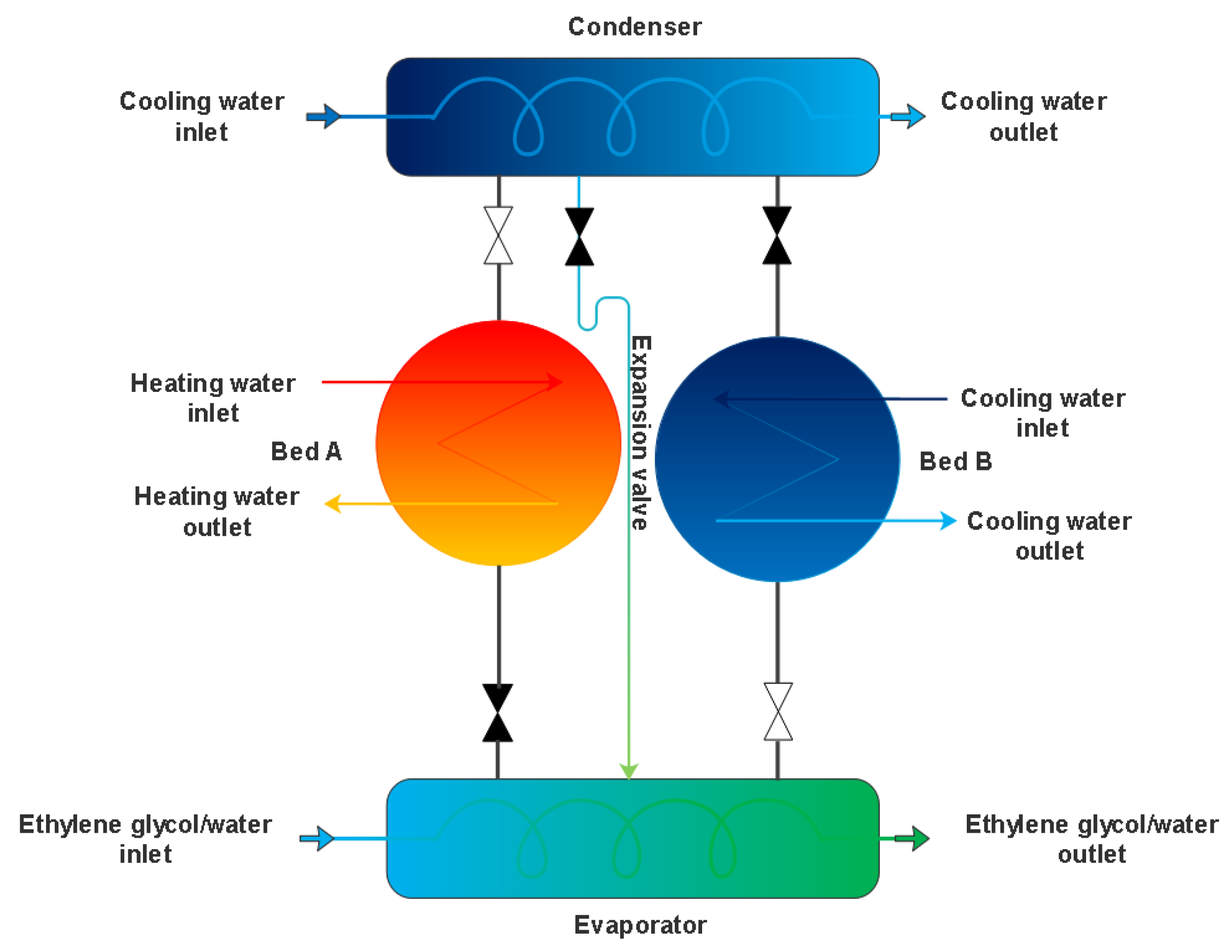
A transient pressure distributed parameter model considering the internal and external mass transfer resistances in the adsorbent domain of an aluminum foamed/finned tube two-bed adsorption system is developed in the current study. Two lumped models of the condenser and evaporator components deeming the heat transfer limits in each component are coupled with the two-bed model at the valve openings as boundary conditions. The coupling of these boundary conditions is switched between the lumped models depending on the mode of operation, in which one bed is connected with the condenser model, and the second is connected with the evaporator model at the same time. During the preheating and precooling modes, the boundaries of the openings are treated as walls.
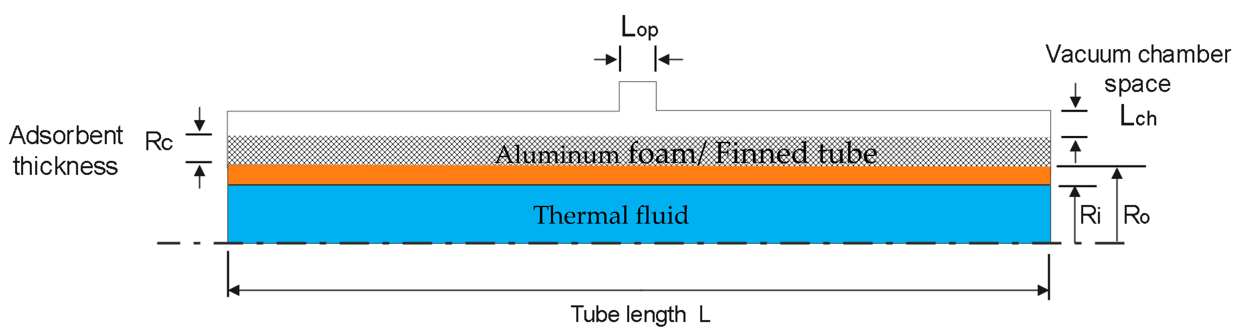
Figure 2 shows a 2-D axisymmetric design model for the representative adsorber tube containing the four domains: the thermal fluid, plain copper tubes, aluminum foam or fins packed with activated carbon, and vacuum space. The developed model embraces the volume averaged approach for solving the conservation equations in the porous adsorbent domain. The current model takes into consideration the non-ideal condenser and evaporator pressures by applying their energy balances at the valve opening as boundary conditions. Solving the governing equations simultaneously reveals the capability of the model to detect the local changes of all variables including the pressure, the temperature, and the amount of adsorbate (uptake) within the investigated adsorbent tube. Each adsorbent bed comprises a bundle of tubes, each of which is identical to the adsorber tube that was used in the simulations. Deducing the overall performance of the system considers the total number of tubes in each bed when connected to the evaporator or the condenser at the four modes of operation. The following assumptions are made in adapting the system of equations used to simulate the adsorption beds:
Ethanol vapor is considered an ideal gas as it works under a high vacuum pressure.
The porosities of the metal foam and the adsorbent material are considered isotropic.
Local thermal equilibrium between the ethanol vapor, adsorbate and adsorbent material.
No thermal losses from outer surfaces of the reaction beds.
3.1. Governing Equations
- a.
Thermal fluid
The liquid water is the thermal fluid flowing inside the copper tubes and used for heating and cooling the beds. A turbulent flow regime for an incompressible fluid is considered, and RANS equations with -ε turbulence model are adopted in the modelling as follows:
Momentum equations
The influence of turbulent flow on the heat transfer propagation inside the tube is imitated in the energy equation using the turbulent thermal conductivity (
term and the energy equation can be written as follows [
23]:
- b.
Metal tube and fins
The conservation of energy for the metal tubes and fins domains is only based on the conduction heat transfer mechanism and can be written as:
- c.
Adsorbent domain
Two forms of mass balance equations are employed in the modelling according to the packing configurations of Maxsorb III. [
15,
36]:
where
is the total porosity in the finned tube beds,
is the bed porosity in the foamed beds,
is the instantaneous adsorbate (uptake),
is the density of ethanol vapor,
is the density of the solid adsorbent and
is the averaged velocity.
The momentum equations are adapted in the modelling in the two following forms [
23]:
is the source term derived from the mass balance Equations (5) and (6) and can be written as:
The energy equation for the adsorbent domain can be expressed as:
where
is the total thermal capacity of the adsorbent domain, which has two forms according to the activated carbon configuration:
is the isosteric heat of adsorption. The thermal conductivity
is considered as the bulk thermal conductivity of Maxsorb in the case of the finned tube bed, while
is the effective thermal conductivity of the foamed packed bed in the case of the aluminum foam bed [
15].
- d.
Vacuum chamber
Typical mass, momentum, and energy conservation equations for a laminar flow of the ethanol vapor in the vacuum space are employed in the modelling and can be written as follows:
Conservation of mass equation:
Conservation of momentum equations:
Conservation of energy equation:
The vapor pressure in both the adsorbent and the vacuum space domains is related to the vapor temperature and density using the ideal gas state equation.
- e.
Evaporator model
The evaporator heat balance equation is used to determine the temperature of evaporation, thereby calculating the evaporator pressure. The heat balance equation considers the effect of the evaporator thermal mass and the heat transfer effectiveness
, as shown in Equation (16)
where
and
is the total number of tubes in the adsorbent bed.
- f.
Condenser model
Similar to the evaporator modelling, the heat balance equation for the condenser considers the effect of the condenser thermal mass and its thermal effectiveness
. Equation (18) is used to determine the ethanol condensing temperature, thus the condenser pressure.
where
and
α and
β are flags used to simulate the current states (on/off) of connecting valves that connect the sorption beds with the evaporator and condenser.
- g.
Adsorption isotherms and kinetics
The linear-driving-force model is defined as a suitable model to represent the resistance to the intraparticle mass transfer [
34,
37]:
where
is the mass transfer coefficient and can be expressed for the Maxsorb III in the granular form as:
is pre-exponential factor, is the universal gas constant and is the activation energy:
For the equilibrium adsorption uptake of Maxsorb III/ethanol (
) [
34,
37]
where,
is the maximum adsorption uptake,
is the gas constant,
is the adsorbent temperature,
is the adsorption characteristics parameter,
is the heterogeneity parameter,
is local pressure and
is the saturation pressure calculated from Antoine’s equation for ethanol by
where,
A,
are equation constants,
is the temperature in °C and
is the pressure in kPa.
- h.
Performance indicators
The performance indicators employed in this study to evaluate the adsorption ice production system are defined by the coefficient of performance (
, the specific cooling power
and the daily ice production (
as follows:
where
is adsorbent mass in the two sorption beds and N is the total cycles in 8 h per day as the system is supposed to be driven by solar energy.
All thermophysical properties, operational parameters, and constant parameters for isotherms used for the simulations are furnished in
Table 1.
Figure 2 illustrates the simulated bed tube and the four associated domains.
3.2. Initial and Boundary Conditions
The effect of the initial conditions on the calculated performance indicators is eliminated after six complete cycles when all variables reached cyclic steady-state conditions. The set of boundary conditions employed in the modelling can be written as follows [
23]:
Thermal fluid at inlet during preheating and desorption modes
Thermal fluid at inlet during precooling and adsorption modes
Valve opening during the desorption mode
Valve opening during the adsorption mode
The parameters used for the condenser and evaporator models are furnished in
Table 2.
3.3. Numerical Procedure
The described mathematical model was built in COMSOL Multiphysics by combining six physics to model all the governing equations simultaneously. For the propagation of heat throughout all the physical domains, Heat Transfer Physics was used. The turbulent flow inside the tubes of the sorption beds was modelled through Turbulent Flow (k − ε) Physics. Furthermore, Free and Porous Media Flow Physics was involved to represent the mass and the momentum transports in the adsorbent and the vacuum domains, especially for handling the interface between those domains. Additionally, Convection–Diffusion Equation Physics for the LDF model was employed. Finally, two Ordinary Differential Equations were correlated to the system of equations to replicate the evaporator and the condenser pressures at the valve opening. User-defined functions were implemented with the six physics to represent all the source terms. In the solver, a time-dependent study was adopted using the segregated approach while setting MUMPS and PARDISO solvers for best convergence. The time step was set to 0.001 s for preheating and precooling processes, and 1 s for desorption and adsorption processes, to accurately catch the changes of the resolved variables. The Grid Convergence Index (GCI) was calculated for the COP and SCP as main output parameters to verify grid independency of the present study using three options including different numbers and sizes of mesh elements. The GCI values were 0.62% and 0.58% for COP and SCP, respectively. The calculation of GCI followed the same procedures that were discussed by Sosnowski in reference [
39]. The maximum change in both COP and SCP was 0.14%. The average mesh element quality was 0.8591 and the maximum growth rates for the boundary mesh elements were 1.08 and 1.1 in the thermal fluid domain, and the adsorbent and vacuum chamber domains, respectively. Therefore, a grid-independent study was established, and the extra-fine choice with about 500,000 mesh elements was selected.
3.4. Validation
The validity of the present numerical model was previously confirmed based on the comparison with the experimental works in references [
23,
40]. Additionally,
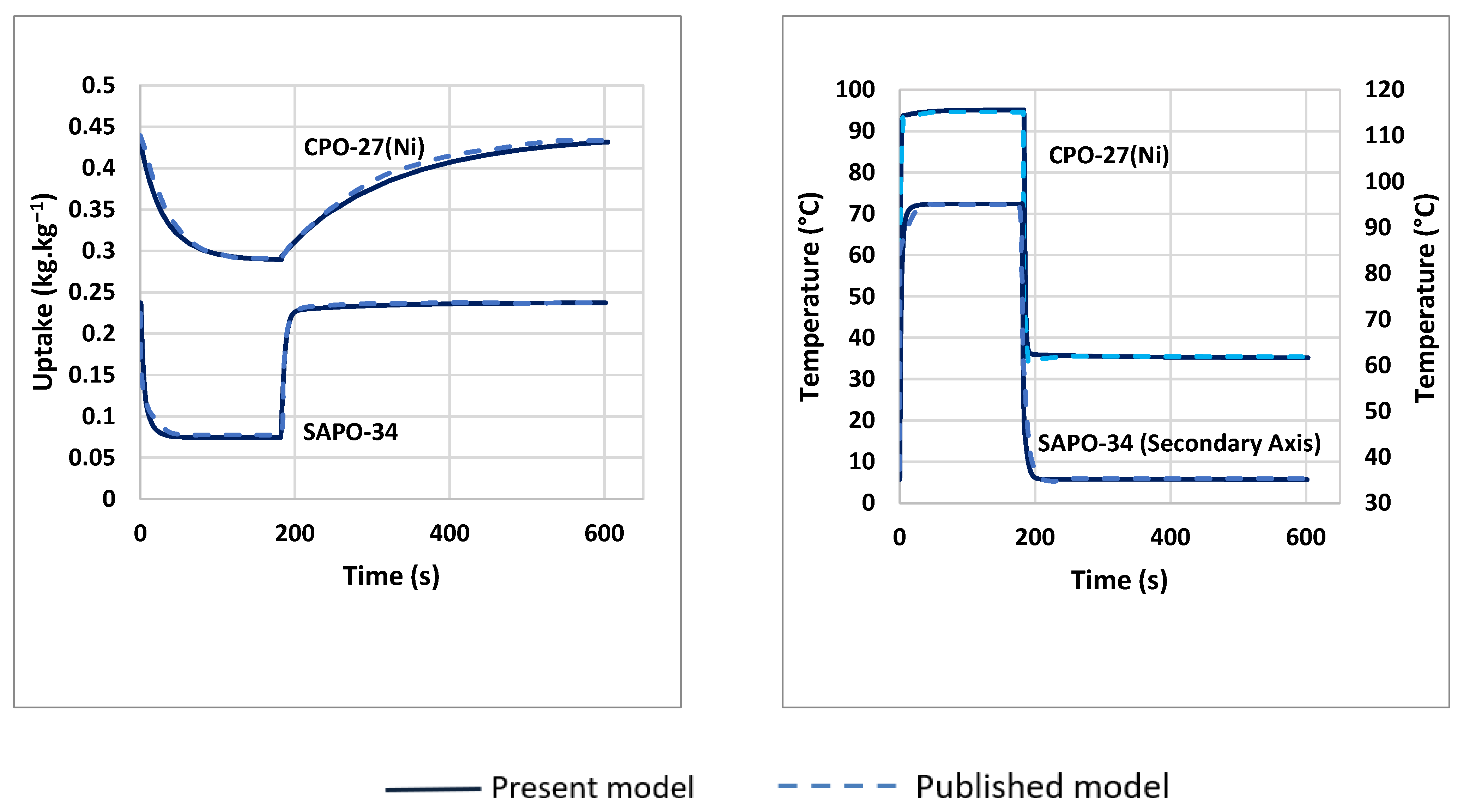
Figure 3 shows the comparison between the results of the present model with data published by Pinheiro et al. [
11] for two adsorbent materials, CPO-27(Ni) and SAPO-34, coated on copper-foam based beds. Very good agreements can be observed between the current model results and the published data.
4. Results and Discussion
The enhancement in the performance of the two-bed adsorption ice production system incorporated foamed beds was investigated by the comparison with the base model of finned tube adsorbent beds at different foam thicknesses/fin heights of 2, 5, and 10 mm and cycle times of 400, 600, 800, 1200 s. In all investigated cases, the total adsorbent mass was kept at 4 kg and 3.8 kg for the finned-tube based system and the Al-foam-based system, respectively, as the Al-foam structure occupied more volume at the same space compared to the fins. This kept identical overall dimensions for both systems at each foam thickness/fin height. The total number of tubes in each bed was set to 309, 95, and 34 at 2 mm, 5 mm, and 10 mm foam thicknesses/fin heights, respectively.
4.1. Numerical Simulation
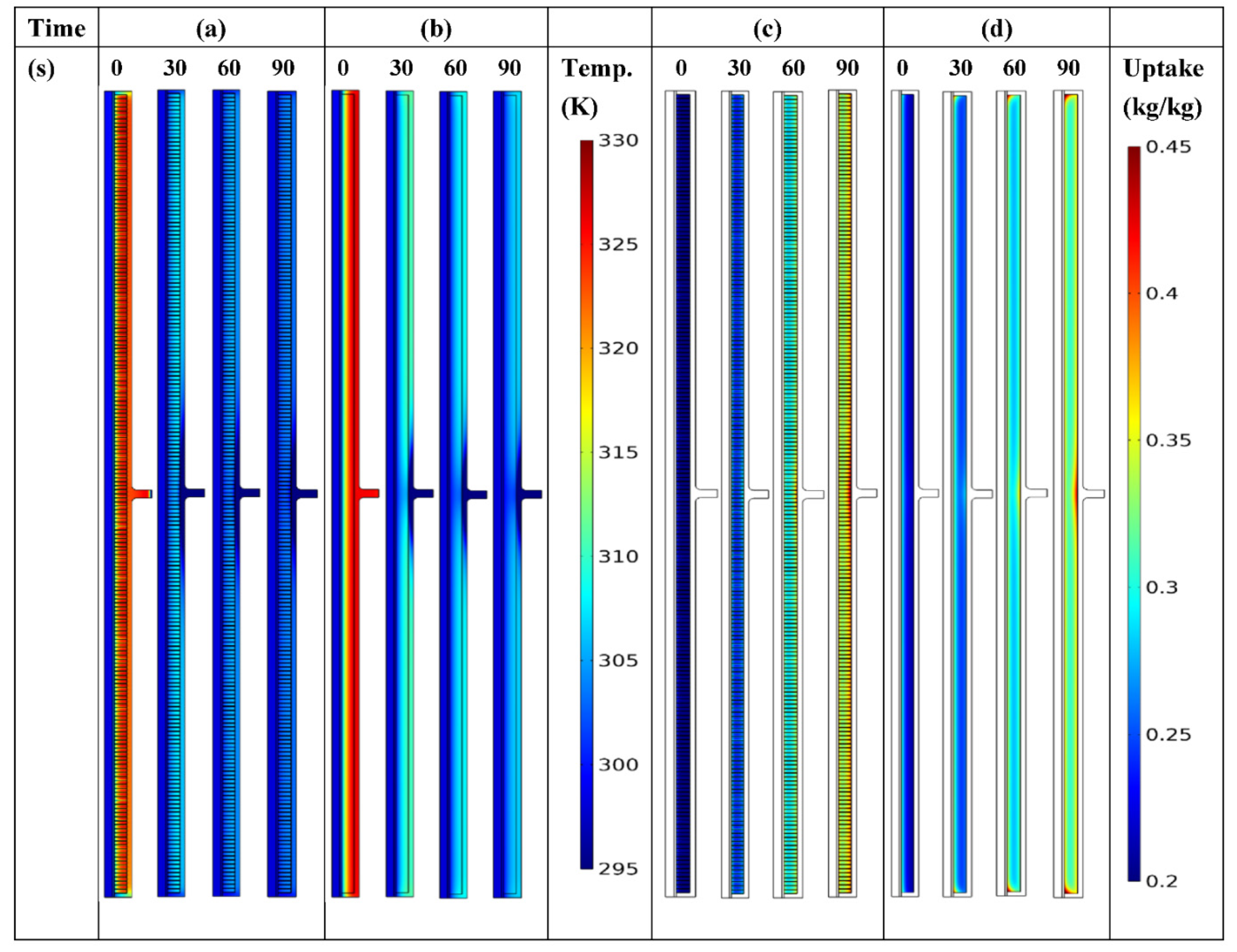
Spatial and temporal variations of the temperature and uptake during the first 90 s of the adsorption process for the bed modelled tube are shown in
Figure 4 for finned-tube and Al-foam beds. The numerical simulation is shown for a 5 mm fin height/foam thickness and cycle time of 400 s. At the starting time of 0 s, the bed just finished the precooling process, and the tube starts to receive the vapor from the evaporator at the valve opening boundary condition. The role of fins and aluminum foam in intensifying the heat transfer within the adsorbent domain is shown in
Figure 4a,b. It can be deduced that a more effective decrease in the bed temperature directly increases the bed uptake and improves the system performance. In detail, the average temperature of the adsorbent domain at 90 s is 26.67 °C for the finned-tube bed compared to 31.21 °C for the Al-foam bed, resulting in an average uptake of 0.363 kg/kg and 0.332 kg/kg for the finned-tube bed and Al-foam bed, respectively. Consequently, and after completing the cycle of 400 s, the DIP of the finned-tube based system and Al-foam based system attained 114.3 and 110 kg
ice·day
−1, respectively. The increase in the DIP of the finned-tube based system over the Al-foam based one was attributed to the lower bed temperature in the former system during the adsorption process in the given case. The net effects of fin height and spacing against the foam thickness at different cycle times on the overall performance of the adsorption ice production system will be discussed in the next sections.
4.2. Effect of Using Fin Height/Foam Thickness of 2 mm
Table 3 shows how the absolute values of the performance indicators are affected by the change in the cycle times. The fin spacing of 1 mm and 2 mm were used for 2 mm fin height in the finned-tube based system. In the case of shorter fin height, all performance indicators improved when the fin spacing changed from 1 mm to 2 mm at each specific cycle time. For both fin spacings, extending the cycle time from 400 s to 1200 s enhanced the COPs by 32% and 35% in the cases of 1- and 2-mm fin spacings, respectively. This is due to the reduction in the sensible heating share with a higher cycle time. However, resulting lower adsorption rates at higher cycle times reduced considerably both SCPs and DIPs. The DIP reduced by 53% and 50% when the cycle time was extended from 400 s to 1200 s, for 1- and 2-mm fin spacings, respectively.
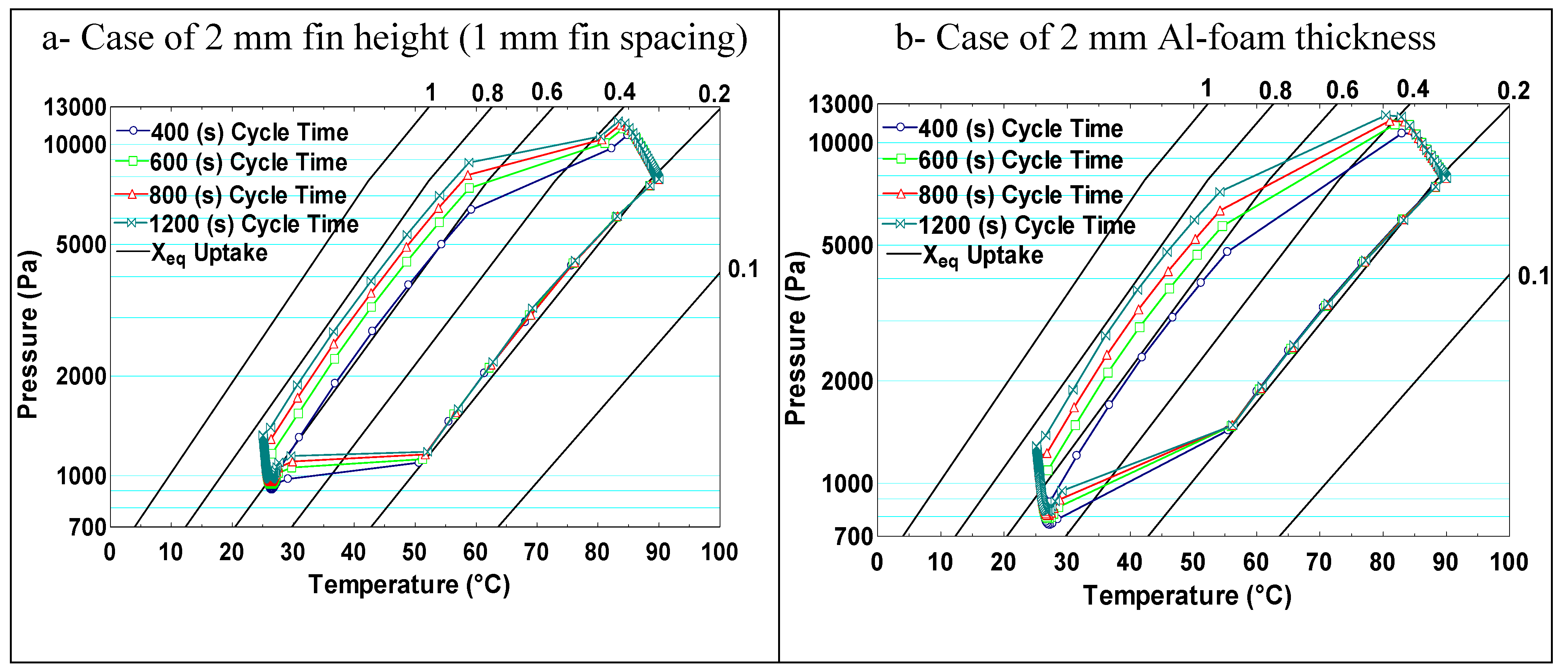
The effects of different cycle times on the average bed temperature, pressure, and uptake during the four processes after reaching cyclic steady-state conditions are shown in
Figure 5 for both systems at 2 mm fin height/foam thickness. It can be deduced that increasing the cycle time increases the effective uptake (the difference between the lower and higher uptakes) for both systems by allowing longer time periods for adsorption and desorption processes, while it was slightly more pronounced in the Al-foam based system. The beds in the Al-foam based system attained lower pressures compared to those in the finned-tube based system. This positively affected the system performance by reducing the temperature of the ethylene glycol/water leaving the evaporator.
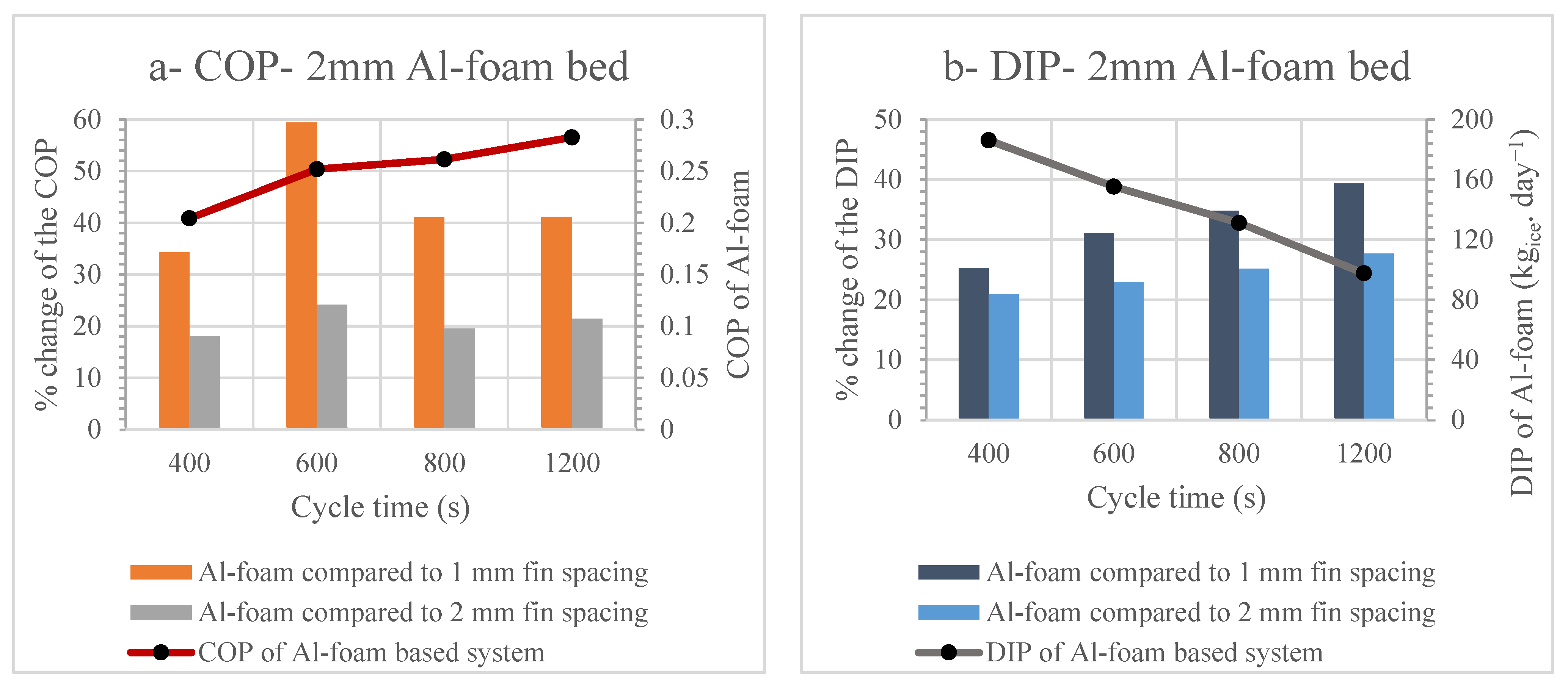
The net effects of changing the cycle time on the percentage change of the COPs and DIPs of the Al-foam two-bed system compared with those resulting from the finned-tube based system are shown in
Figure 6. It is clearly seen that the Al-foam based system outperformed the finned-tube based system in both COPs and DIPs at different cycle times and both fin spacings of 1 mm and 2 mm. This was attributed to the lower temperature of the ethylene glycol/water leaving the evaporator and the lower adsorbent mass associated with the Al-foam based system, compared with those associated with the finned-tube based system for the given cases.
The maximum increase in the COP of the Al-foam based system reached 59.4% at a cycle time of 600 s, while the DIP of the Al-foam based system reached its maximum percentage increase of 39.3% at a cycle time of 1200 s, compared with the finned-tube based system with 1 mm fin spacing. Moreover,
Figure 6 shows how the COP and DIP of the Al-foam based system was affected by changing the cycle time. Increasing the cycle time enhanced the system COP but reduced the DIP at the given short foam height of 2 mm. This was attributed to the lower rate of adsorption with increasing time as the uptake approaches its upper limit in the given condition. It is important to mention that the Al-foam based system at a cycle time of 400 s can produce ice at a maximum of 186.2 kg
ice·day
−1 with the system COP at 0.204, while extending the cycle time to 1200 s can considerably reduce the DIP to 97.8 kg
ice·day
−1 with an enhancement in the system COP to 0.284.
4.3. Effect of Using Fin Height/Foam Thickness of 5 mm
The absolute values of the COP, SCP, and DIP resulting from the finned-tube based system at 5 mm fin height are depicted in
Table 4 for 1 mm and 2 mm fin spacings. Compared to the 2 mm fin height,
Table 3, the system COP was enhanced noticeably with increasing the fin height to 5 mm and this was more pronounced at 2 mm fin spacing. However, the system SCP and DIP were affected negatively by increasing the fin height from 2 mm to 5 mm. For example, DIPs were reduced by 20.6% and 3.6% at cycle times of 400 s and 1200 s, respectively. This was a direct result of the reduction in the effective uptakes that can be noticed when comparing
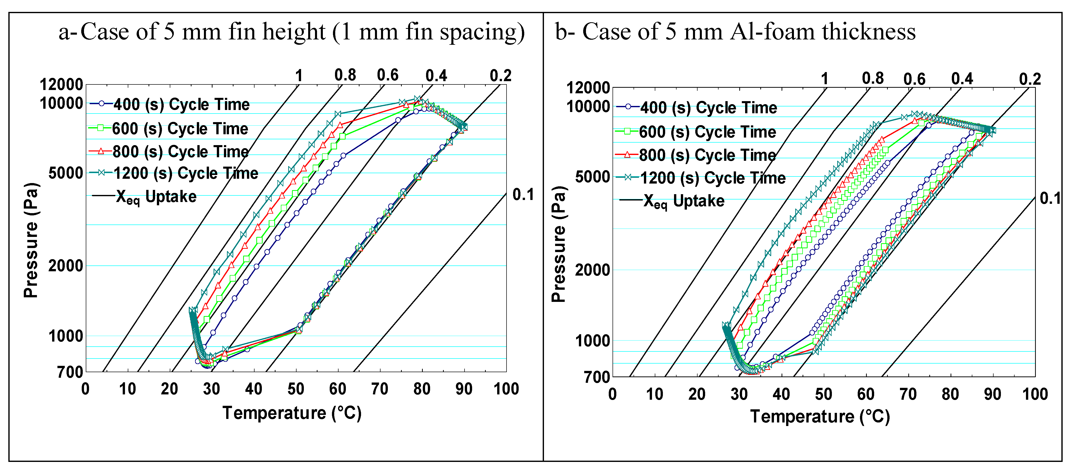
Figure 5a and
Figure 7a.
At a cycle time of 400 s, the effective uptake in the foamed bed was much lower than that attained by the finned-tube bed, as can be shown by comparing
Figure 7a,b, for 5 mm fin height/foam thickness. Increasing the cycle time enhanced considerably both beds’ uptake at the end of the adsorption process. In the foamed bed, the lower limit of the uptake at the end of the desorption process decreased with increasing the cycle time and reached about 0.2 kg/kg at a cycle time of 1200 s. This affected positively the performance of the Al-foam based system for the higher cycle time.
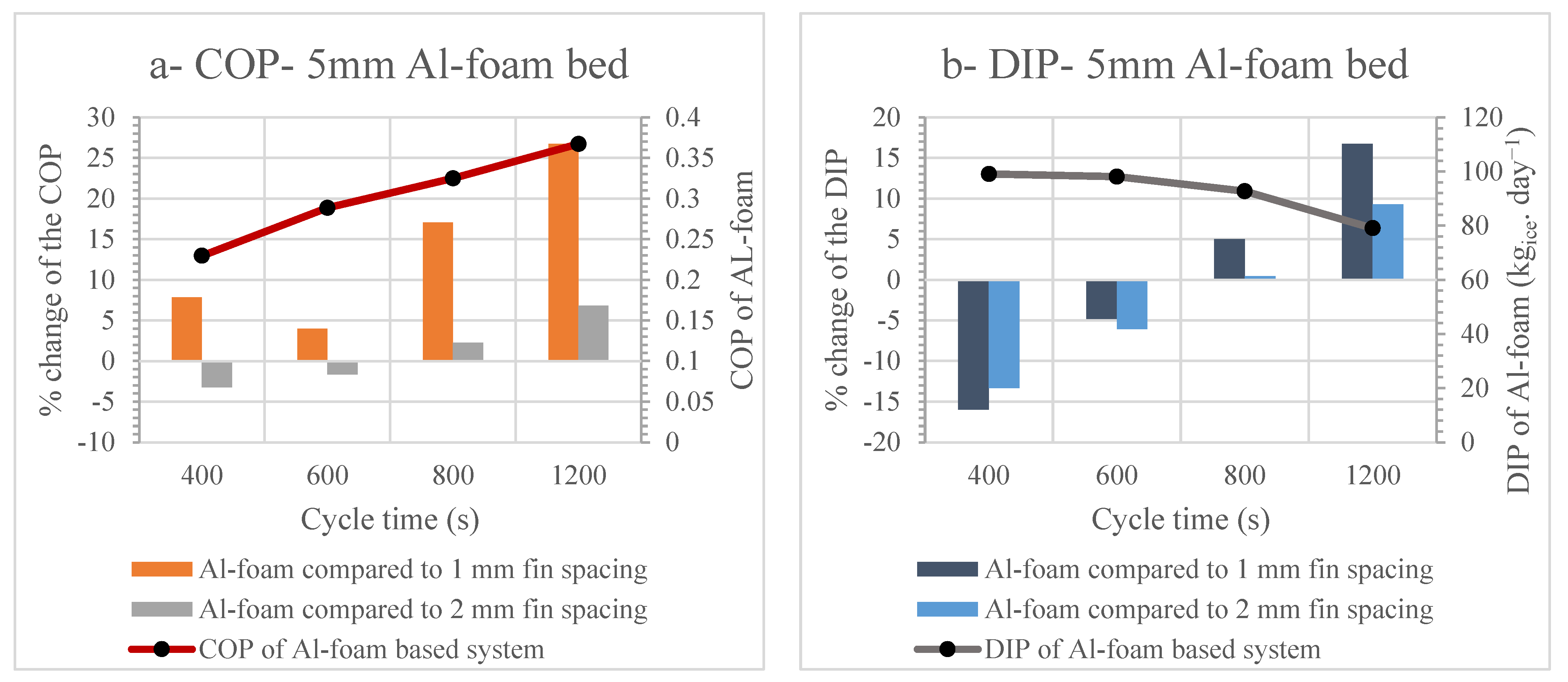
The net effects of changing the cycle time on the percentage change in the COP and DIP of the adsorption system when fixing the fin height/foam thickness at 5 mm are shown in
Figure 8. The COPs of the Al-foam based system outperformed those of the finned-tube based system with 1 mm fin spacing at all cycle times. The maximum increase of the COP was 26.7% at 1200 s. However, using the foamed beds to enhance the COP compared to the finned-tube based system with 2 mm fin spacing can only be achieved at higher cycle times of 800 s (2.3% increase) and 1200 s (6.8% increase), as shown in
Figure 8a.
Working at higher cycle times of 800 s and 1200 s can also enhance the DIPs of the Al-foam based system over those of the finned-tube based system with both 1- and 2-mm fin spacings. The maximum increase of only 16.8% (which was 39.3% at 2 mm foam thickness,
Figure 6b in the DIP of the Al-foam based system was attained at a cycle time of 1200 s and 5 mm foam thickness, as shown in
Figure 8b. This was due to the negative effect of using less adsorbent mass in the foamed beds compared to the finned-tube beds, which was not compensated by higher heat and mass transfer enhancement as in the case of 2 mm foam thickness. Additionally, the performance of the Al-foam based system was affected more negatively by the reduction of the total number of tubes used in each bed (the total number was reduced from 309 to 95 tubes). The reduction in the number of tubes leads to a reduction in cooling and heating mass flow rates in the case of 5 mm foam thickness.
Using a foam thickness of 5 mm was better in terms of the system COP compared to 2 mm foam thickness at each cycle time. The maximum COP of 0.366 for the Al-foam based system was attained at a cycle time of 1200 s, as shown in
Figure 8. On the other hand, the DIP was reduced by 20.1% (from 99.1 to 79.1 kg
ice·day
−1) when changing the cycle time from 400 s to 1200 s, compared to a 47.5% reduction (from 186.2 to 97.6 kg
ice·day
−1) in the same case with 2 mm foam thickness.
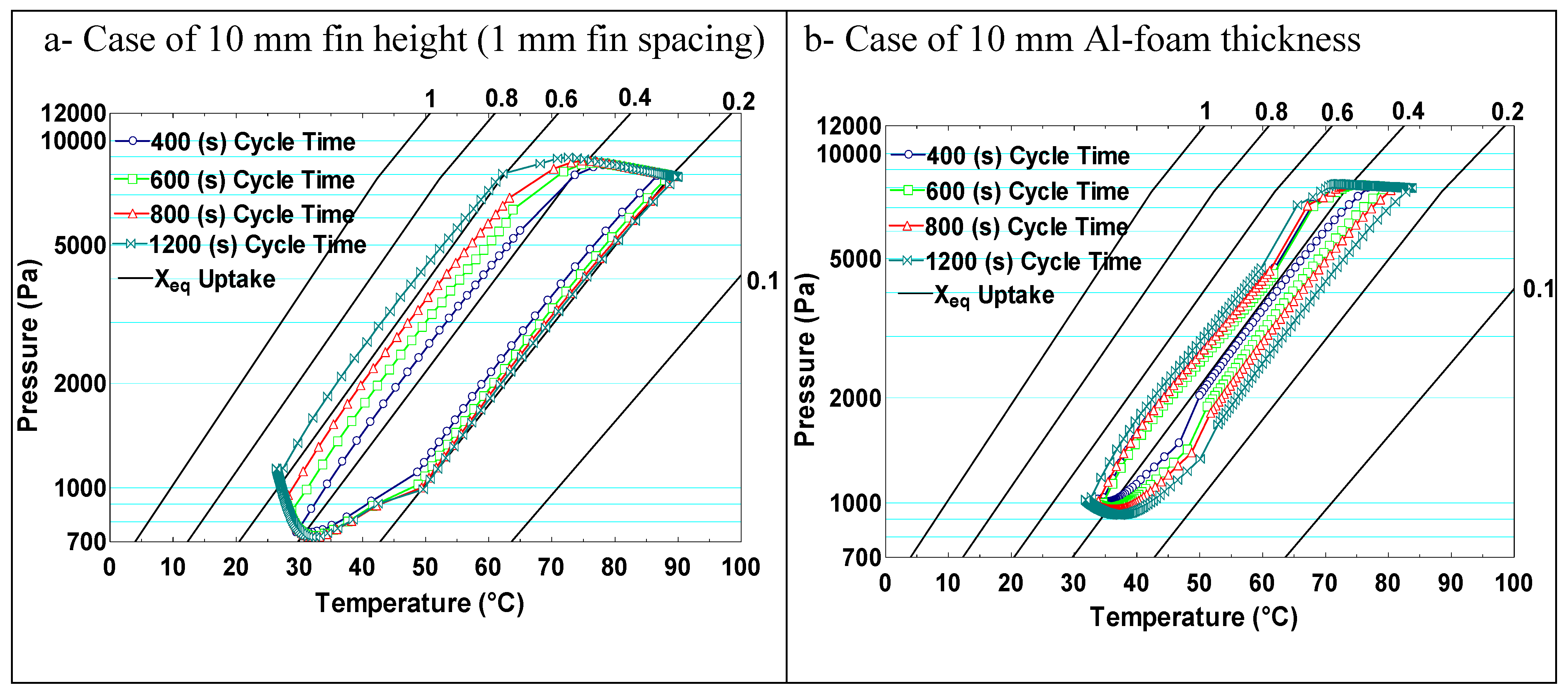
4.4. Effect of Using Fin Height and Foam Thickness of 10 mm
Increasing the fin height from 5 mm to 10 mm enhanced the COP of the finned-tube two-bed adsorption ice production system at only a longer cycle time, as can be deduced from the comparison between
Table 4 and
Table 5. The COP increased by 13.8% when the fin height of 10 mm replaced that of 5 mm at 1mm fin spacing and 1200 s cycle time. The maximum COP of 0.37 was attained at a cycle time of 1200 s with 2 mm fin spacing. However, both the SCP and DIP were reduced considerably by 43.3% at a shorter cycle time of 400 s when using a 10 mm fin height instead of 5 mm.
Figure 9 illustrates how the average effective uptake, pressure, and temperature in the adsorbent domain were significantly changed while simulating the two beds of each configuration in two identical systems with 10 mm fin height/foam thickness. The effective uptake of the Al-foam based bed was reduced dramatically compared with that of the finned-tube based bed at all cycle times and worsened at shorter cycle times. The smaller number of adsorbers’ tubes used with 10 mm fin height/foam thickness (34 tubes in each bed) negatively affected the effective uptake in the Al-foam based system to a much greater degree than in the finned-tube one. This was attributed to the lower permeability in the adsorbent domain of the foamed bed, which was one-half less than that in the finned bed system, recalling that the effect of the permeability increases with a higher foam thickness. Consequently, the increase of the mass transfer resistance demolished the enhancement in the heat transfer through the foamed adsorbent bed.
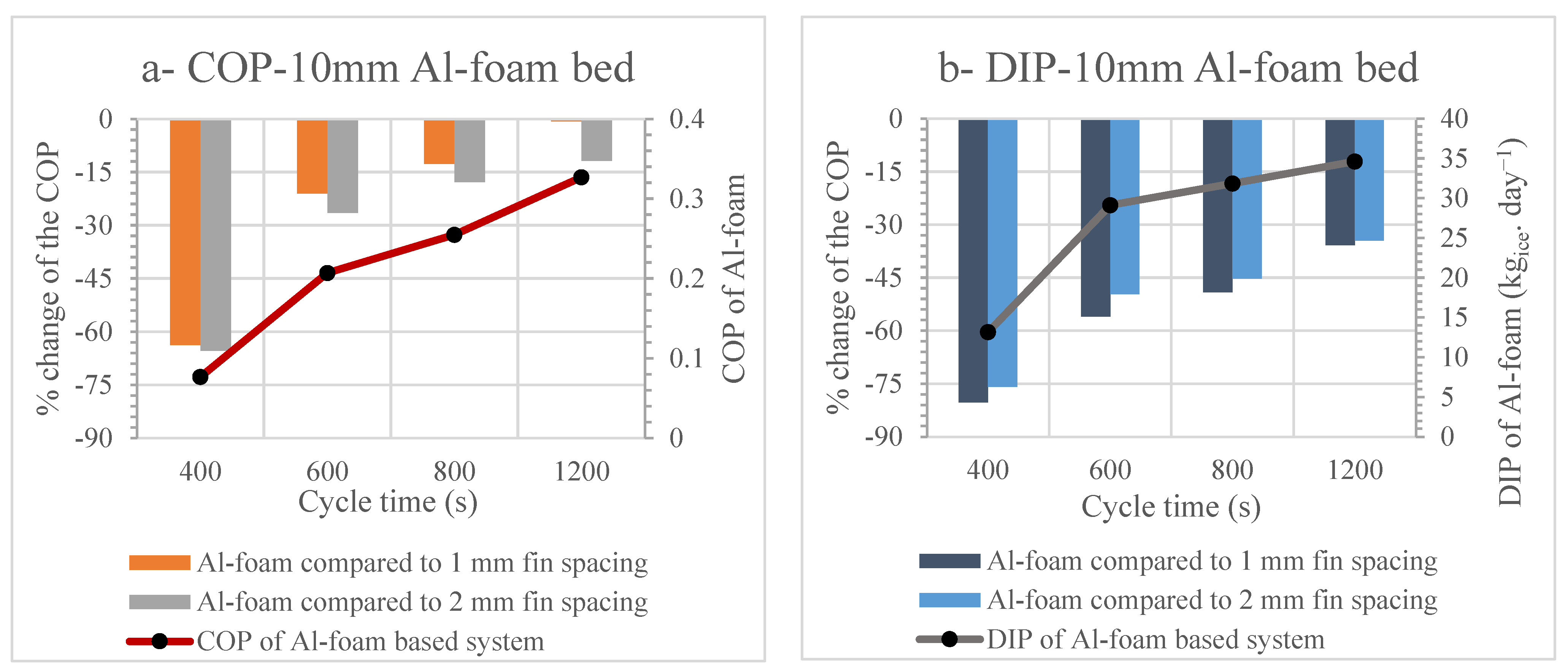
Figure 10 demonstrates the net effect of changing the cycle time using 10 mm foam thickness compared with the finned tube bed of 10 fin height on the COP and DIP of the two-bed adsorption ice maker. The COP and DIP of the Al-foam based system were reduced dramatically when a higher foam thickness of 10 mm was employed. The system COP and DIP were reduced by 63.8% and 75.8% at a cycle time of 400 s, while they were reduced by 1% and 35.8% at a cycle time of 1200 s, respectively, compared with the base model of 1 mm fin spacing.
Increasing the cycle time from 400 s to 1200 s in the case of the Al-foam based system enhanced considerably both COP and DIP as they increased by 326% and 163%, respectively. Using the higher foam thickness of 10 mm should be associated with higher cycle time, which needs more investigation in future work as a small number of tubes in the adsorbent bed could be preferred to reduce the circulated heating and cooling water flow rates in a certain application. In addition, an adsorbent bed with ethanol refrigerant in adsorption ice production systems works under very high vacuum pressures, which makes the mass transfer mechanisms in the adsorbent domain play a critical role. In such a case, increasing the permeability of the foamed adsorbent bed is a crucial requirement to enhance the performance of Al-foam based adsorption ice production systems compared to the finned-tube one.


 ,
, 


