
Development of Equivalent Circuit Models of Permanent Magnet Synchronous Motors Considering Core Loss


1
National Engineering Laboratory for Electric Vehicles, Beijing Institute of Technology, Beijing 100081, China
2
School of Electrical and Data Engineering, University of Technology Sydney, Sydney, NSW 2007, Australia
3
School of Electrical and Information Engineering, The University of Sydney, Sydney, NSW 2006, Australia
*
Author to whom correspondence should be addressed.
Energies 2022, 15(6), 1995; https://doi.org/10.3390/en15061995
Submission received: 12 January 2022
/
Revised: 2 March 2022
/
Accepted: 7 March 2022
/
Published: 9 March 2022
Abstract
:Permanent magnet synchronous motor (PMSM) possesses the advantages of low power loss, high power density and high torque density and, hence, has achieved broad applications in both industrial drives and home appliances. With the increasing demands for high power density, the PMSM often operates at high speed and high frequency, leading to high power loss and temperature rise. Consequently, proper consideration of power loss, including the core loss, has attracted much attention for the modelling, designing, controlling and optimizing of PMSMs. However, the widely used equivalent circuit model, capable of providing good analysis results with fast calculation, often ignores the core loss, which may lead to unsatisfactory motor performance. This paper aims to investigate the development of equivalent circuit models, with predictable core loss for PMSMs, and proposes novel equivalent circuit models, which improve the core loss prediction accuracy in the load conditions. Some thoughts about the further improvement of the models are proposed and discussed.
1. Introduction
A permanent magnet (PM) synchronous motor (PMSM) is a kind of synchronous motor with permanent magnets to provide the field excitation. Thus, the PMSM does not need a DC source for excitation, resulting in low copper loss, high power density and torque density. Consequently, PMSMs have been widely used in both industrial drives and home appliances. Recently, the surge in demand for highly efficient PMSMs has been mainly caused by electric vehicles (EVs) and hybrid electric vehicles (HEVs) [1,2]. One of the requirements in the PMSM design is to save energy and achieve high efficiency, over a broad torque and speed range, especially in the applications where the motor is supplied by power-limited batteries, e.g., EVs and HEVs. Higher efficiency of the PMSM means lower loss, whilst understanding and modelling all kinds of electromagnetic loss correctly are the basis of the loss minimum design and control strategies. In PMSMs, generally, there are three main types of loss, i.e., copper loss, core loss, and mechanical loss. Among them, the core loss may account for a significant component of the total loss of a PMSM, especially for the high-speed operations, since the core loss increases dramatically with the increase in the motor speed. In addition, the thermal effects due to the power loss, including core loss, directly influence the irreversible demagnetization of PM, the cooling design, and the volume of PMSMs. Therefore, proper core loss calculation and modelling have significant influences on the performance, efficiency and temperature rise in PMSMs.
The equivalent circuit model (ECM) is the most widely used method for electric machine analysis. By analyzing the ECM, electric device performance, such as the relationships among currents and voltages, input power, output power, efficiency and power factor, can be calculated conveniently. Traditionally, the core loss component is neglected in the ECM, but this may suffer from the risk of low computation accuracy, resulting in limited application for modern high-performance PMSM design and control. Moreover, in both traditional vector control and in flourishing model predictive control of PMSMs, the ECM lays the basis for establishing the control strategies and, hence, excluding the core loss component may lead to inaccurate analysis results, far away from practical operation conditions. By contrast, ECM with predictable core loss provides promising solutions for the above-mentioned issues, which is drawing more and more attention.
This paper aims to present the development of the PMSM equivalent circuit models considering the core loss. Section 2 presents the prototypes and the conventional ECM of PMSMs and discusses the limitations of the conventional ECM. Section 3 investigates the per-phase ECMs with predictable core loss, and Section 4 studies the ECMs with separate d-axis and q-axis circuits, which are commonly used for PMSMs. Section 5 proposes novel ECMs with predictable core loss and verifies them using simulations. Then, a brief review of core loss calculation methods is given in Section 6. Section 7 concludes the paper by proposing and discussing some thoughts for further improving the core loss prediction and the development trends of the ECM.
2. Prototypes and the Conventional ECMs of PMSMs
There are various prototypes of PMSM, such as the surface-mounted PMSM [3], interior PMSM [4], claw-pole PMSM [5], transverse flux PMSM [6], and axial flux PMSM [7], as shown in Figure 1. The structures of the prototypes show significant differences, but their operating principle, in terms of electromagnetic energy conversion, is consistent. Therefore, it is fundamental to extract the key electromagnetic parameters of the PMSM and present them in an ECM, or in mathematical equations, to conduct motor performance analysis, control and optimization.
In the most studied cases of the PMSM, the per-phase ECM, neglecting the core loss, is illustrated in Figure 2, while the d- and q-axis ECMs are demonstrated in Figure 3. In Figure 2, Rs is the winding resistance of per-phase, and the power loss of Rs presents the copper loss of the PMSM. Ls is the synchronous inductance, which is an equivalent inductance of self-inductance and mutual-inductance per-phase. The PMSM is excited by PMs, and the PM flux is described by λf, while rotating PMs induce the back electromotive force E0, which is proportional to the rotor speed in electrical angular frequency, ωe. Moreover, Ip and Vp are the phase current and voltage, respectively. To realize the vector control of the PMSM, ECM or mathematical model in the three-phase stationary reference frame, we must transform this to the two-phase rotational reference frame, as shown in Figure 3, where Vd and Vq are the d- and q-axis terminal voltages, Id and Iq are the d- and q-axis armature currents, and Ld and Lq are the d- and q-axis inductances, respectively.
The ECMs and mathematical models, mentioned above, cannot provide high-precision solutions during motor design, control and optimization, due to the absence of the core loss. The copper loss can be estimated via the power loss on winding resistance Rs, while the core loss cannot be predicted from any parameters in these models. Actually, the core loss may rise significantly and exceed the copper loss, when the motor speed increases and the load torque grows. Ignoring the core loss also leads to underestimation of other performances.
In conclusion, due to neglecting the core loss component, the drawbacks of the conventional ECMs of the PMSM mainly contain:
- (1)
- Inconvenience for core loss calculation, control, and optimization;
- (2)
- Poor theoretical foundation to support the motor efficiency prediction, thermal management, and cooling design;
- (3)
- Overestimation of the output electromagnetic torque and power for a given input current, resulting in lower control performance; and
- (4)
- Exacerbation of the parameter sensitivity of the model-based motor control system, such as the model predictive control.
Therefore, further studying and establishing the ECM of the PMSM with predictable core loss has vitally important theoretical significance and engineering value.
3. Per-Phase ECM with Predictable Core Loss
Due to the complex mechanism, the core loss modeling in the ECM is still a pending issue. Although incorporating the core loss in ECM is important, only a small amount of research has been carried out in this area, and most of this was in the 1980s. This section and the next are presented to investigate the main publications with various topologies of ECM of PMSMs with predictable core loss, and all the ECMs describe the permanent magnet synchronous machine working as a motor.
The earliest record of the ECM of PMSMs with predictable core loss may be in 1980 [8], when Honsinger reported an ECM of AC permanent magnet machines, as illustrated in Figure 4. Strictly speaking, the core loss is comprised of three components: hysteresis loss, eddy current loss, and anomalous loss or excess loss. However, a considerable number of researchers divided the core loss into just two parts: hysteresis loss and eddy current loss. The eddy current loss simply varies with the square of the terminal voltage, whereas the empirical index for the hysteresis loss is in the range of 1.6–1.9 and that for the anomalous loss is 1.5. For different types of cores, this three components account for various proportions, e.g., in soft magnetic composite and amorphous magnetic alloy core, the hysteresis loss may be the dominant part, while in silicon steel core, the major component may be the eddy current loss. In a permanent magnet machine, the core loss appears due to the magnetizing flux and leakage flux, and the core loss caused by the leakage flux can be neglected, especially under a no-load condition. At fixed speed and frequency, the core loss can be considered approximately proportional to the square of magnetic flux or back electromotive force (EMF):
where kc is a constant. Therefore, the equivalent core loss may be represented by a resistor, in parallel with the magnetizing branch. As shown in Figure 1, the core loss in the stator core is considered by a power loss consumed in an equivalent core loss resistor rc, placed across the internal voltage Ei. It is noted that the impedance Zi may contain the synchronous inductance, as well as the distributed capacitance.
Figure 5 proposed the most widely used per-phase ECM of PMSMs with predictable core loss, and this topology was first introduced by Colby and Novotny in 1987 [9]. The key to using ECM to predict the core loss of PMSMs is how to identify the value of the equivalent core loss resistance Rc, and a more accurate value of Rc can bring a better analysis solution of PMSMs’ performance. In Colby and Novotny’s original work, the equivalent core loss resistance Rc is modelled as a single-valued resistance, and it was evaluated by measuring the torque required to drive the PMSM as a generator at no-load conditions.
However, the core loss is frequency-dependent, i.e., the core loss varies with motor speed, so the single-valued equivalent core loss resistor is insufficient to describe the whole speed range of the PMSM. To deal with this problem, the authors of this paper presented an ECM with variable core loss resistance, as in Figure 6 [10]. The model was used to analyze a permanent magnet motor with soft magnetic composite core, in which the hysteresis loss dominates, and reasonably accurate results were obtained.
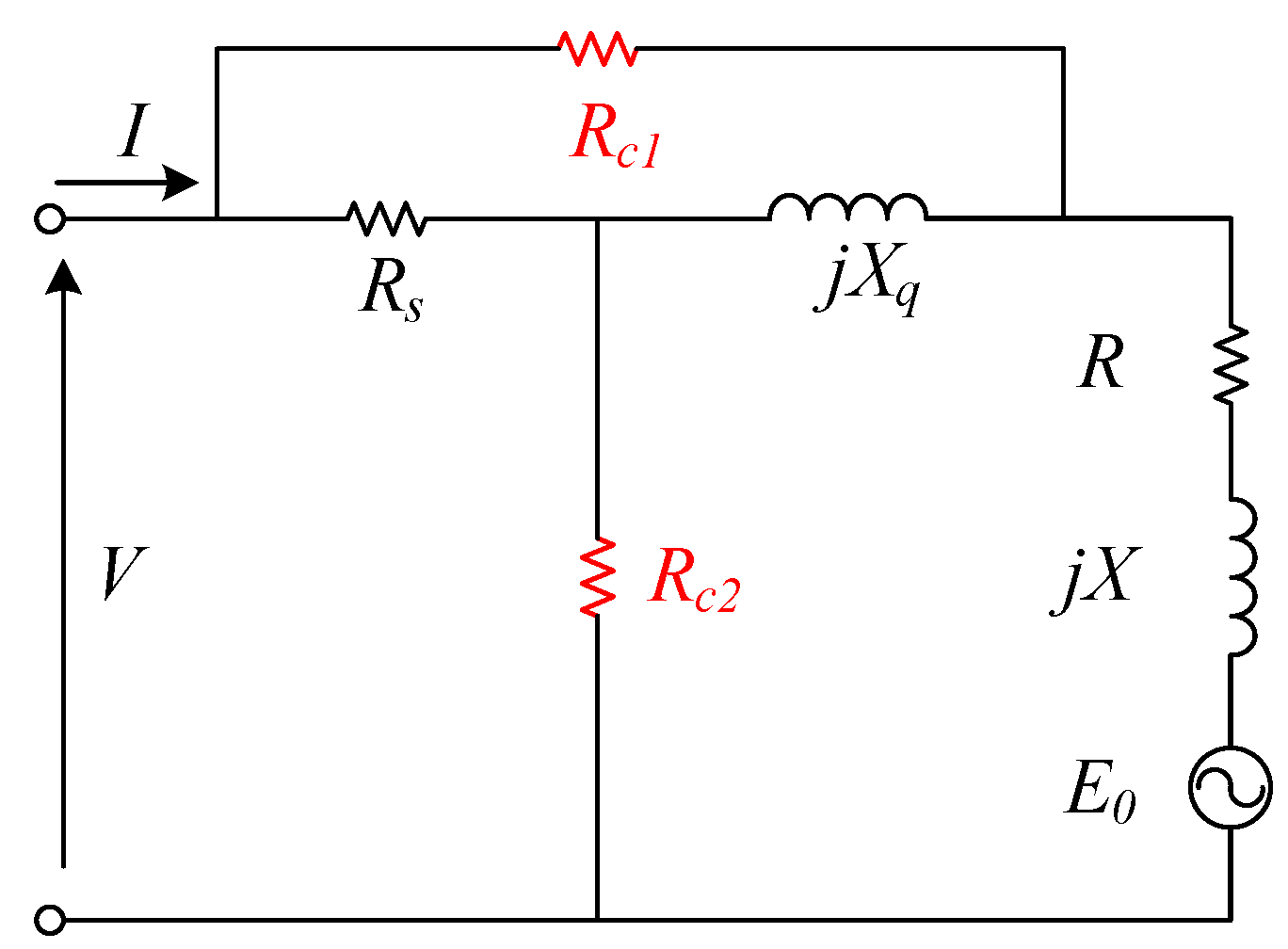
In order to express the core loss changes with the terminal voltage and current of interior permanent magnet synchronous motor (IPMSM), Consoli and Renna [11] established an ECM with two equivalent core loss resistance, i.e., Rc1 and Rc2, as illustrated in Figure 4. The resistance Rc2, conventionally placed in parallel with the internal EMF of the motor, accounts for the small power which is lost in the motor at the no-load condition. This resistance is calculated through the values of voltage and current at this point and accounts for the voltage-dependent core loss of the machine. On the other hand, Rc1 is included, which carries part of the input current to model the core loss component relevant to the stator current. Additionally, the d-axis inductance is different from the q-axis inductance in the IPMSM and, hence, two parameters, R and X, are incorporated to represent the saliency of the motor, and R = (Xd − Xq)sinγcosγ, X = (Xd − Xq)sin2γ, while γ is the reaction angle and Xd are Xq the d-axis and q-axis reactance, respectively. For the surface-mounted permanent magnet synchronous motor (SPMSM), Xd = Xq, and R and X are zero and the ECM, as in Figure 7, also can be adopted.
As a further step of Figure 7, Consoli and Raciti [12] developed the ECM of PMSMs with salient pole, as shown in Figure 8. In this ECM, both the core loss and the saliency effects of the machine are taken into account by introducing parameters Rcv, Rci, R, and X. To be more specific, the equivalent resistance Rcv, placed in parallel with the total voltage induced in the stator winding, accounts for the voltage-dependent core loss, while the equivalent resistance Rci, carrying part of the phase stator current, accounts for the current-related core loss. The resistance R and the reactance X are introduced to describe the saliency effects of the machine, and they are zero when the machine has no saliency. Circuit parameter determination relies on experimental tests on the machine, and no-load, as well as loaded conditions, are analyzed. The main difference between Figure 7 and Figure 8 is where to place the equivalent current-related core loss resistance, and there are only slight differences in the results.
4. d- and q-Axis ECM of PMSM with Predictable Core Loss
The most widely used ECM of PMSMs, based on the synchronous d-q reference frame, considering the core loss, is presented in Figure 9 [13,14,15,16,17,18]. In the figure, the equivalent core loss resistance Rc is connected in parallel with the d- and q-axis magnetizing branch, respectively. Essentially, Figure 9 can be regarded as the equivalent ECM of Figure 2, after applying reference frame transformation.
Figure 9 shows the most popular ECM of the PMSM, but its mathematical equations corresponding to the circuit model contain some errors [13,14,15,16,17]. Here, the mathematical models are modified as:
where Vd and Vq are the d- and q-axis terminal voltages, Id and Iq are the d- and q-axis armature currents, Vod and Voq are the d- and q-axis internal voltages, Iod and Ioq are the d- and q-axis magnetizing currents, Icd and Icq are the d- and q-axis mechanical and core loss currents, and Ld and Lq are the d- and q-axis inductances, respectively. Rc is the equivalent core loss resistance, Rs is the armature winding resistance per-phase, λf is the permanent magnet linkage, ωe is the rotor speed in electrical angular frequency, and p is the differential operator (=d/dt).
The electromagnetic torque Tem and electromagnetic power Pem of PMSMs can be determined as:
where P is the number of pole pairs of the PMSM, and ωm is the rotor speed in mechanical angular frequency.
The copper loss Pcu and the core loss Pc can be estimated as:
Then, the total main loss of PMSM, which consists of the copper loss, core loss and mechanical loss, is expressed as:
where Pmech is the mechanical loss of PMSM.
Ignoring the eddy current loss of permanent magnets, the output power, input power, and efficiency of the PMSM are calculated as:
where Poutput is the output power, Pin is the input power, and η is the efficiency of the PMSM.
To apply the ECM in motor characteristic analysis, the parameters, including the equivalent core loss resistance, should be identified properly. Generally, there are two methods to determine the value of the equivalent core loss resistance, i.e., numerical calculation, based on finite element analysis (FEA), and prototype tests at no-load conditions. In [13], the core loss of PMSM is calculated based on FEA, and the harmonic components of magnetic flux density are concerned, while the core loss at each element is calculated from the summation of the core loss generated from different frequencies of the magnetic flux density. Finally, the total core loss of the PMSM is obtained by the summation of the core loss in all the elements. After calculating the total core loss Wc, the equivalent core loss resistance Rc can be determined as:
Figure 10 [19,20] presented another kind of d-and q-axis ECM of PMSMs. In this ECM, Lls is the leakage inductance per-phase, and Lmd and Lmq are the d-axis and q-axis component of the magnetizing inductance, respectively. Figure 10 separated the d- and q-axis inductances into magnetizing inductances and leakage inductances, and both of them contribute to the core loss.
Nevertheless, in the opinion of the authors of this paper, the ECM of PMSMs, considering the leakage inductances under the d- and q-axis reference frame, should be modified, as shown in Figure 11, and Ll is the leakage inductance per-phase. The flux linkage generated by phase windings can be expressed in terms of the leakage linkage and the magnetizing linkage. However, the leakage flux only links the stator winding itself and does not contribute much to the core loss of the stator. Therefore, the magnetizing flux linkages, in which the equivalent core loss resistances are paralleled, should exclude the leakage inductances.
After the reference frame transformation, the three-phase sinusoidal currents under the abc reference frame can be recognized as direct currents under the d-and q-axis reference frame. Therefore, based on the concept of the direct currents, the voltages across the d-and q-axis inductances would be zero in the steady state, resulting in the elimination of the d-and q-axis inductances in the equivalent circuit model of PMSMs [21,22,23,24,25,26,27], as shown in Figure 12 [25]. For the determination of the equivalent core loss resistance Rc, although the value of Rc changes with the operating conditions, [22,25] calculated it from the results of tests performed at nominal voltage and synchronous speed, i.e., Rc is assumed to be a constant in that condition.
When the PMSM is operated in the high-speed region, the field-weakening control strategy is generally applied. During this condition, the harmonic components of the flux become more significant, especially in load conditions, and this might lead to underestimation of the core loss. Therefore, in [28], the harmonic components are considered by increased voltage drops across the equivalent core loss resistance, while the circuit model is illustrated in Figure 13. Since the harmonic inductances Lh are added, the additional voltage drops ωeLhIoq and ωeLhIod would increase the power consumed by the equivalent core loss resistance Rc.
By using the Fourier analysis, harmonic components of flux at load conditions can be identified, and then each component is divided by the fundamental component of current and added together. Thus, the harmonic inductance Lh can be calculated, as shown in (17). Besides, the corresponding voltage equations of this ECM are expressed as in (18) and (19).
where Ia, Iod, and Ioq are the phase current, d- and q-axis currents, λf and λoi the linkage flux generated by permanent magnets and the i-th harmonic component of flux linkage, respectively.
Furthermore, the no-load core loss is obtained by using FEA and the corresponding resistance Rc1 is expressed by a function of speed as:
where Rc1 is the equivalent core loss resistance, calculated at no-load condition, Wi1 the no-load core loss, λo1 the no-load flux linkage, ωe1 the reference angular speed, and a and b are coefficients.
The core loss resistance, corresponding to load condition Rc2, can be expressed as:
where Rc2 is the equivalent core loss resistance, calculated at load condition, and λo2 the load flux linkage.
As shown in Figure 14, an ECM of the PMSM, which is suitable for high-frequency differential mode calculation, was proposed in [29]. The differential mode branch contains series r0LDMdCDMd (r0LDMqCDMq) combination to stand for the second resonance, while the differential mode capacitance CDM, together with the motor inductance Ls, almost determines the value of the first resonance. Moreover, LDMd and LDMq are the d- and q-axis differential mode leakage inductances. The equivalent core loss resistance Rc is normally of high value, and determined from the maximum value of the measured input impedance at the resonance frequency.
Taking into account not only the copper loss and core loss, but also the PM loss, Ref. [30] introduced an ECM with a series-parallel structure, as shown in Figure 15. RFe and RPM are the equivalent core loss and PM loss resistances, respectively, and they are indirectly achieved, based on finite element method (FEM) results.
5. Proposed ECMs with Predictable Core Loss
Although, increasingly, researchers have realized the importance of the core loss, the generalized ECMs of the PMSM with predictable core loss have still been underdeveloped during the past decades. There are two crucial points in developing the ECM:
- (1)
- Where the equivalent core loss resistance should be put, i.e., which branch the equivalent core loss resistance should be connected, to predict the core loss in both no-load and loading conditions.
- (2)
- How to identify the value of the equivalent core loss resistance, i.e., it should be a constant or a function of motor parameters.
The no-load core loss is generated from the PMs’ flux, and obviously increases with the motor speed or frequency. The load core loss is yielded from the resultant flux of both PMs and winding currents. More importantly, the load core loss cannot continue to increase with the current or load due to the nonlinear magnetic properties of the stator core. To reflect the above characteristics in the ECMs, a novel per-phase ECM of PMSM with predictable core loss is proposed in Figure 16, and d- and q-axis ECM is developed in Figure 17. In them, Rs is the armature winding resistance per-phase, Rco the no-load equivalent core loss resistance, Rci the load equivalent core loss resistance, E0 the back electromotive force, λf the permanent linkage, and ωe is the rotor speed in electrical angular frequency. Ip and Vp are phase current and voltage, Vd and Vq the d- and q-axis terminal voltages, Id and Iq the d- and q-axis armature currents, and Ld and Lq are the d- and q-axis inductances, respectively.
According to the proposed per-phase ECM, the following mathematical equations are obtained:
The no-load and load core loss Pco and Pci can be, respectively, calculated as:
According to Figure 17, the mathematical models of the equivalent circuits for d- and q-axis voltages and currents are given as follows:
where Icid and Iciq are, respectively, the d- and q-axis load core loss currents, Imd, Imiq, and Imq the d- and q-axis magnetizing currents, while Ico is the no-load core loss currents.
Therefore, the no-load and load core loss Pco and Pci can be, respectively, calculated as:
Please note that the values of Rco and Rci in the per-phase ECM are equal to that in the dq axis ECM. Two methods are proposed to identify the values of Rco and Rci:
- (1)
- Numerical calculation based on the finite element method. Compute the no-load core loss versus the motor speed (frequency), and then determine the no-load equivalent core loss resistance Rco, as a function of the motor speed (frequency) via data fitting. Work out the load core loss at the rated operating point, and then evaluate the load equivalent core loss resistance Rci as a constant.
- (2)
- Experimental tests. Similar procedures as (1), but all data are acquired by the experimental tests on the prototype.
To verify the proposed ECMs, an interior PMSM (IPMSM) is investigated, and the parameters of the motor are shown in Table 1.
It has been seen that the no-load equivalent core loss resistance is a function of the motor speed, and it is calculated via FEM, while the load equivalent core loss resistance has fixed value.
It is very hard to compare the proposed ECMs with every reviewed ECM, since some of them have less portability and extensibility. Figure 6 (per-phase ECM) and Figure 9 (dq axis ECM) are the most widely used configurations, so they are selected as the compared counterpart with the proposed ECM. The equivalent core loss resistance identification is another key issue, compared with using a single-value equivalent core loss resistance to predict the core loss during the entire operating range, to model it as a function of motor speed in [10] has better accuracy. Therefore, the equivalent core loss resistance in the compared counterpart will be established as a function of motor speed, which is obtained from no-load core loss [10].
Figure 18 illustrates the core loss versus motor speed, calculated by three methods. The green line represents the core loss computed by FEM, which increases, evidently, with the motor speed and winding current. Since the proposed ECM and the compared conventional ECM adopt the same method to model the no-load core, as a function of motor speed, the predicted core loss is equal and able to accurately follow the FEM results, in a wide speed range, as shown in Figure 18a. The main difference between the proposed ECM and conventional ECM, in terms of the model structure, is which branch the load equivalent core loss resistance is connected to, while in terms of the function, it is how to calculate the additional core loss due to the winding current. When the IPMSM is fed by the rated current, the calculated core loss versus motor speed by three methods is presented in Figure 18b. The blue line shows the predicted core loss by the proposed ECM, and the average error between it and FEM is 9.1%, while the maximum error is 19% (in low-speed range) and the minimum error is 3.8% (around rated speed). The predicted core loss by the conventional ECM is described by the red line, and the average error between it and FEM is 69%, while the maximum error is 150% (in low-speed range) and the minimum error is 44% (around rated speed). It is seen that the proposed ECM can dramatically enhance the core loss prediction accuracy.
To have an overview of all the ECMs with predictable core loss mentioned above, a comparison is made with five indicators, as shown in Table 2.
6. Core Loss Calculation Methods
The most general practice for computing the core loss is to divide it into two or three terms, i.e., the hysteresis loss, eddy current loss, and anomalous loss, while a two-term model ignores the anomalous loss term. Assuming the excitation magnetic field is alternating, the alternating core loss can be calculated as [31,32,33,34,35]:
The three terms in the right side represent, respectively, the hysteresis, eddy current, and anomalous loss items, where f and BP are the flux density frequency and peak value, while Cha, Cea, Caa, and h are coefficients, depending on material properties.
However, in the stator core of the PMSM, the trajectories of the flux density are not only alternating, but also rotational, and with high-order harmonics. Considering the rotational core loss, many researchers decomposed the flux density into its radial and tangential components Br and Bt [36,37,38], and modified the core loss calculation models based on the equation below:
where Pr is the rotational core loss, and Chr, Cer, Car, and h are coefficients of stator material under rotational magnetic field. Strictly speaking, these coefficients are different in the alternating and rotational magnetic fields, but many researchers made a confusing explanation. In addition, a number of researchers ignore the rotational anomalous loss (the last term of (33)).
The main shortcoming of Equation (33) is that it cannot accurately compute the rotational hysteresis loss when the flux density is near the saturation value, since the rotational hysteresis loss cannot continually rise with the increase in the magnetic field, and it drops dramatically and vanishes when the flux density reaches the saturation value. Therefore, the following models are established to depict the special characteristic of the rotational core loss and rotational hysteresis loss [39,40,41]:
where Pr is the rotational core loss, BP the peak value of the circularly rotating B vector, Bs is the saturation value of flux density, and s, a1, a2, and a3 are all coefficients.
7. Conclusions and Discussion
ECM is able to calculate the electromagnetic properties of the PMSM in an intuitive way. However, the conventional ECMs ignore the core loss, resulting in low accuracy and difficulty to control and optimize the core loss. This paper investigated the development of the PMSM ECMs with predictable core loss, and it is noted that, generally, the equivalent core loss resistance is connected in parallel with the magnetizing branch. This is based on the assumption that the core loss is approximately proportional to the square of the flux density and the machine runs at a fixed speed, e.g., synchronous speed. However, modern PMSMs often operate with variable frequency (speed) and variable flux density (e.g., changing load condition), so the core loss would change, accordingly. Therefore, novel ECMs, with a predictable core loss and equivalent core loss identification method, are established. Compared with the conventional ECM, considering the core loss, the proposed ECMs can effectively increase the accuracy when the motor runs in loading conditions. In addition, a brief review of core loss calculation methods is introduced to help understanding of both alternating core loss and rotational core loss.
The significance of the ECM with predictable core loss is not only to predict the core loss, but more importantly, it has rewritten the calculation models of the PMSM, such as electromagnetic torque, magnetizing current, and efficiency, resulting in higher accurate solutions, which cover every aspect of the PMSM. In addition, the ECM with predictable core loss needs to improve and developed further. There are two development trends of the ECM with predictable core loss, according to the authors’ understanding:
- (1)
- Develop the equivalent core loss resistance identification method, based on a deep understanding of the physical mechanism and effective mathematical modeling of various factors. Taking the alternating core loss, rotational core loss, and nonlinear magnetic properties of the stator core into consideration, determine the equivalent core loss resistance to present the characteristic of the PMSM, across the entire operating range.
- (2)
- Explore the application of the ECM with predictable core loss. Taking the motor control as an example, such as direct torque control, field-oriented control, and model prediction control, the mathematical models (equivalent to the ECM) of the PMSM are necessary, and a high-precision model can provide many possibilities to improve the control performance, and [42] made an attempt at this. Moreover, in the system-level multi-physics and robust design and optimization [43,44] of PMSM, advanced ECMs with accurate and fast calculations are also necessary.
Author Contributions
Conceptualization, X.B., Y.G. and J.Z.; methodology, X.B. and Y.G.; software, Z.G.; validation, Y.G., C.Z. and J.Z.; formal analysis, Y.G.; investigation, Z.G.; resources, Y.G.; data curation, X.B. and Y.G.; writing—original draft preparation, X.B. and Y.G.; writing—review and editing, X.B., Y.G., Z.G. and J.Z.; visualization, Z.G. and C.Z.; supervision, Y.G., C.Z. and J.Z.; project administration, Y.G.; funding acquisition, Y.G. and C.Z. All authors have read and agreed to the published version of the manuscript.
Funding
This research received no external funding.
Institutional Review Board Statement
Not applicable.
Informed Consent Statement
Not applicable.
Data Availability Statement
Not applicable.
Conflicts of Interest
The authors declare no conflict of interest.
References
- Chau, K.T.; Chan, C.C.; Liu, C. Overview of Permanent-Magnet Brushless Drives for Electric and Hybrid Electric Vehicles. IEEE Trans. Ind. Electron. 2008, 55, 2246–2257. [Google Scholar] [CrossRef] [Green Version]
- Zhu, Z.Q.; Howe, D. Electrical Machines and Drives for Electric, Hybrid, and Fuel Cell Vehicles. Proc. IEEE 2007, 95, 746–765. [Google Scholar] [CrossRef]
- Hwang, S.-W.; Lim, M.-S.; Hong, J.-P. Hysteresis Torque Estimation Method Based on Iron-Loss Analysis for Permanent Magnet Synchronous Motor. IEEE Trans. Magn. 2016, 52, 8204904. [Google Scholar] [CrossRef]
- An, Y.; Ma, C.; Zhang, N.; Guo, Y.; Degano, M.; Gerada, C.; Li, Q.; Zhou, S. Open-Circuit Air-Gap Magnetic Field Calculation of Interior Permanent Magnet Synchronous Motor With V-Shaped Segmented Skewed Poles Using Hybrid Analytical Method. IEEE Trans. Magn. 2021, 57, 8108309. [Google Scholar] [CrossRef]
- Liu, C.; Lu, J.; Wang, Y.; Lei, G.; Zhu, J.; Guo, Y. Design Issues for Claw Pole Machines with Soft Magnetic Composite Cores. Energies 2018, 11, 1998. [Google Scholar] [CrossRef] [Green Version]
- Liu, C.; Lei, G.; Wang, T.; Guo, Y.; Wang, Y.; Zhu, J. Comparative Study of Small Electrical Machines With Soft Magnetic Composite Cores. IEEE Trans. Ind. Electron. 2017, 64, 1049–1060. [Google Scholar] [CrossRef]
- Zhao, J.; Hua, M.; Liu, T. Research on a Sliding Mode Vector Control System Based on Collaborative Optimization of an Axial Flux Permanent Magnet Synchronous Motor for an Electric Vehicle. Energies 2018, 11, 3116. [Google Scholar] [CrossRef] [Green Version]
- Honsinger, V.B. Performance of Polyphase Permanent Magnet Machines. IEEE Trans. Power Appar. Syst. 1980, PAS-99, 1510–1518. [Google Scholar] [CrossRef]
- Colby, R.S.; Novotny, D.W. Efficient Operation of Surface-Mounted PM Synchronous Motors. IEEE Trans. Ind. Appl. 1987, IA-23, 1048–1054. [Google Scholar] [CrossRef]
- Ba, X.; Guo, Y.; Zhu, J.; Zhang, C. An Equivalent Circuit Model for Predicting the Core Loss in a Claw-Pole Permanent Magnet Motor With Soft Magnetic Composite Core. IEEE Trans. Magn. 2018, 54, 8206706. [Google Scholar] [CrossRef]
- Consoli, A.; Renna, G. Interior type permanent magnet synchronous motor analysis by equivalent circuits. IEEE Trans. Energy Convers. 1989, 4, 681–689. [Google Scholar] [CrossRef]
- Consoli, A.; Raciti, A. Analysis of permanent magnet synchronous motors. IEEE Trans. Ind. Appl. 1991, 27, 350–354. [Google Scholar] [CrossRef]
- Hur, J. Characteristic Analysis of Interior Permanent-Magnet Synchronous Motor in Electrohydraulic Power Steering Systems. IEEE Trans. Ind. Electron. 2008, 55, 2316–2323. [Google Scholar] [CrossRef]
- Lee, J.-Y.; Lee, S.-H.; Lee, G.-H.; Hong, J.-P.; Hur, J. Determination of parameters considering magnetic nonlinearity in an interior permanent magnet synchronous motor. IEEE Trans. Magn. 2006, 42, 1303–1306. [Google Scholar] [CrossRef]
- Song, J.; Jung, D.; Kim, S.; Lee, S.; Park, H.; Kim, D.; Park, S.; Kwon, S.; Kim, Y.; Hong, J. Power density improvement design of the traction motor for the hybrid electric vehicle. In Proceedings of the INTELEC 2009—31st International Telecommunications Energy Conference, Incheon, Korea, 18–22 October 2009; pp. 1–4. [Google Scholar]
- Fernandez-Bernal, F.; Garcia-Cerrada, A.; Faure, R. Determination of parameters in interior permanent-magnet synchronous motors with iron losses without torque measurement. IEEE Trans. Ind. Appl. 2001, 37, 1265–1272. [Google Scholar] [CrossRef]
- Dutta, C.; Tripathi, S.M. Comparison between conventional and loss d-q model of PMSM. In Proceedings of the 2016 International Conference on Emerging Trends in Electrical Electronics & Sustainable Energy Systems (ICETEESES), Sultanpur, India, 11–12 March 2016; pp. 256–260. [Google Scholar]
- Uddin, M.N.; Rahman, M.M.; Patel, B.; Venkatesh, B. Performance of a loss model based nonlinear controller for IPMSM drive incorporating parameter uncertainties. IEEE Trans. Power Electron. 2019, 34, 5684–5696. [Google Scholar] [CrossRef]
- Ojo, O.; Osaloni, F.; Wu, Z.; Omoigui, M. A control strategy for optimum efficiency operation of high performance interior permanent magnet motor drives. In Proceedings of the 38th IAS Annual Meeting on Conference Record of the Industry Applications Conference, 2003, Salt Lake City, UT, USA, 12–16 October; 2003; Volume 1, pp. 604–610. [Google Scholar]
- Solomon, O.; Famouri, P. Control and efficiency optimization strategy for permanent magnet brushless AC motors. In Proceedings of the 2009 IEEE International Symposium on Industrial Electronics, Seoul, Korea, 5–8 July 2009; pp. 505–512. [Google Scholar]
- Bernal, F.F.; Garefa-Cerrada, A.; Faure, R. Loss-minimization control of synchronous machines with constant excitation. In Proceedings of the PESC 98 Record, 29th Annual IEEE Power Electronics Specialists Conference (Cat. No.98CH36196), Fukuoka, Japan, 22–22 May 1998; Volume 1, pp. 132–138. [Google Scholar]
- Deleanu, S.; Carpenter, D.; Lau, M. Determination of parameters of a synchronous motor with radial permanent magnets and rotor damper bar cage. In Proceedings of the 2012 25th IEEE Canadian Conference on Electrical and Computer Engineering (CCECE), Montreal, QC, Canada, 29 April–2 May 2012; pp. 1–6. [Google Scholar]
- Bernal, F.F.; Cerrada, A.G.; Faure, R. Model-based loss minimization for DC and AC vector-controlled motors including core saturation. IEEE Trans. Ind. Appl. 2000, 36, 755–763. [Google Scholar] [CrossRef]
- Morimoto, S.; Tong, Y.; Takeda, Y.; Hirasa, T. Loss minimization control of permanent magnet synchronous motor drives. IEEE Trans. Ind. Electron. 1994, 41, 511–517. [Google Scholar] [CrossRef]
- Monajemy, R.; Krishnan, R. Control and dynamics of constant-power-loss-based operation of permanent-magnet synchronous motor drive system. IEEE Trans. Ind. Electron. 2001, 48, 839–844. [Google Scholar] [CrossRef]
- Schaible, U.; Szabados, B. Dynamic motor parameter identification for high speed flux weakening operation of brushless permanent magnet synchronous machines. IEEE Trans. Energy Convers. 1999, 14, 486–492. [Google Scholar] [CrossRef]
- Tong, Y.; Morimoto, S.; Takeda, Y.; Hirasa, T. Maximum efficiency control for permanent magnet synchronous motors. In Proceedings of the IECON ’91: 1991 International Conference on Industrial Electronics, Control and Instrumentation, Kobe, Japan, 28 October–1 November 1991; pp. 283–288. [Google Scholar]
- Lee, B.H.; Kwon, S.O.; Sun, T.; Hong, J.P.; Lee, G.H.; Hur, J. Modeling of core loss resistance for d-q equivalent circuit analysis of IPMSM considering harmonic linkage flux. IEEE Trans. Magn. 2011, 47, 1066–1069. [Google Scholar] [CrossRef]
- Adam, A.A. Accurate modeling of PMSM for differential mode current and differential torque calculation. In Proceedings of the 2013 International Conference on Computing, Electrical and Electronic Engineering (ICCEEE), Khartoum, Sudan, 26–28 August 2013; pp. 103–109. [Google Scholar]
- Xie, W.; Wang, X.; Wang, F.; Xu, W.; Kennel, R.; Gerling, D. Dynamic Loss Minimization of Finite Control Set-Model Predictive Torque Control for Electric Drive System. IEEE Trans. Power Electron. 2016, 31, 849–860. [Google Scholar] [CrossRef]
- Tao, D.; Zhou, K.L.; Lv, F.; Dou, Q.; Wu, J.; Sun, Y.; Zou, J. Magnetic Field Characteristics and Stator Core Losses of High-Speed Permanent Magnet Synchronous Motors. Energies 2020, 13, 535. [Google Scholar] [CrossRef] [Green Version]
- Ji, W.; Ni, F.; Gao, D.; Luo, S.; Lv, Q.; Lv, D. Electromagnetic Design of High-Power and High-Speed Permanent Magnet Synchronous Motor Considering Loss Characteristics. Energies 2021, 14, 3622. [Google Scholar] [CrossRef]
- Si, J.; Zhao, S.; Feng, H.; Hu, Y.; Cao, W. Analysis of temperature field for a surface-mounted and interior permanent magnet synchronous motor adopting magnetic-thermal coupling method. CES Trans. Electr. Mach. Syst. 2018, 2, 166–174. [Google Scholar] [CrossRef]
- Balamurali, A.; Feng, G.; Lai, C.; Tjong, J.; Kar, N.C. Maximum Efficiency Control of PMSM Drives Considering System Losses Using Gradient Descent Algorithm Based on DC Power Measurement. IEEE Trans. Energy Convers. 2018, 33, 2240–2249. [Google Scholar] [CrossRef]
- Yao, A.; Sugimoto, T.; Odawara, S.; Fujisaki, K. Core Loss Properties of a Motor With Nanocrystalline Rotor and Stator Cores Under Inverter Excitation. IEEE Trans. Magn. 2018, 54, 8203205. [Google Scholar] [CrossRef]
- Zhang, C.; Chen, L.; Wang, X.; Tang, R. Loss Calculation and Thermal Analysis for High-Speed Permanent Magnet Synchronous Machines. IEEE Access 2020, 8, 92627–92636. [Google Scholar] [CrossRef]
- Feng, Y.; Zhang, C. Core Loss Analysis of Interior Permanent Magnet Synchronous Machines under SVPWM Excitation with Considering Saturation. Energies 2017, 10, 1716. [Google Scholar] [CrossRef] [Green Version]
- Denis, N.; Inoue, M.; Fujisaki, K.; Itabashi, H.; Yano, T. Iron Loss Reduction in Permanent Magnet Synchronous Motor by Using Stator Core Made of Nanocrystalline Magnetic Material. IEEE Trans. Magn. 2017, 53, 8110006. [Google Scholar] [CrossRef]
- Guo, Y.; Zhu, J.; Lu, H.Y.; Li, Y.; Jin, J. Core Loss Computation in a Permanent Magnet Transverse Flux Motor With Rotating Fluxes. IEEE Trans. Magn. 2014, 50, 6971480. [Google Scholar] [CrossRef] [Green Version]
- Guo, Y.; Zhu, J.; Lu, H.; Lin, Z.; Li, Y. Core Loss Calculation for Soft Magnetic Composite Electrical Machines. IEEE Trans. Magn. 2012, 48, 3112–3115. [Google Scholar] [CrossRef]
- Guo, Y.; Zhu, J.G.; Watterson, P.A.; Wu, W. Development of a PM Transverse Flux Motor With Soft Magnetic Composite Core. IEEE Trans. Energy Convers. 2006, 21, 426–434. [Google Scholar] [CrossRef]
- Ba, X.; Wang, P.; Zhang, C.; Zhu, J.G.; Guo, Y. Improved Deadbeat Predictive Current Control to Enhance the Performance of the Drive System of Permanent Magnet Synchronous Motors. IEEE Trans. Appl. Supercond. 2021, 31, 0603004. [Google Scholar] [CrossRef]
- Lei, G.; Wang, T.; Zhu, J.; Guo, Y. Robust multiobjective and multidisciplinary design optimization of electrical drive systems. CES Trans. Electr. Mach. Syst. 2018, 2, 409–416. [Google Scholar] [CrossRef]
- Lei, G.; Wang, T.; Zhu, J.; Guo, Y.; Wang, S. System-Level Design Optimization Method for Electrical Drive Systems—Robust Approach. IEEE Trans. Ind. Electron. 2015, 62, 4702–4713. [Google Scholar] [CrossRef]
Figure 1.
Prototypes of the PMSM: (a) surface-mounted PMSM; (b) interior PMSM; (c) claw-pole PMSM; (d) transverse flux PMSM; (e) axial flux PMSM.
Figure 1.
Prototypes of the PMSM: (a) surface-mounted PMSM; (b) interior PMSM; (c) claw-pole PMSM; (d) transverse flux PMSM; (e) axial flux PMSM.

Figure 2.
Conventional per-phase ECM of PMSM.

Figure 3.
Conventional d- and q-axis ECMs of PMSM: (a) d-axis; (b) q-axis.

Figure 4.
Per-phase ECM with predictable core loss of PMSMs [8].
Figure 4.
Per-phase ECM with predictable core loss of PMSMs [8].

Figure 5.
Per-phase ECM with predictable core loss of PMSMs [9].
Figure 5.
Per-phase ECM with predictable core loss of PMSMs [9].

Figure 6.
ECM of PMSM with Rc as function of speed [10].
Figure 6.
ECM of PMSM with Rc as function of speed [10].

Figure 7.
Per-phase ECM with predictable core loss of PMSMs [11].
Figure 7.
Per-phase ECM with predictable core loss of PMSMs [11].

Figure 8.
Per-phase ECM with predictable core loss of PMSMs [12].
Figure 8.
Per-phase ECM with predictable core loss of PMSMs [12].

Figure 9.
ECM of PMSMs with predictable core loss: (a) d-axis; (b) q-axis.


Figure 11.
ECM of PMSMs considering core loss and leakage inductance: (a) d-axis; (b) q-axis.


Figure 16.
Proposed per-phase ECM of PMSM with accurate core loss prediction.

Figure 17.
Proposed ECM of PMSM with accurate core loss prediction: (a) d-axis; (b) q-axis.

Figure 18.
Core loss versus motor speed: (a) no-load conditions; (b) rated current conditions.


Table 1.
Parameters of the IPMSM.
| Parameter | Symbol | Value |
|---|---|---|
| Number of pole pairs | P | 4 |
| Stator winding resistance | Rs | 0.0974 Ω |
| d-axis inductance | Ld | 83.955 μH |
| q-axis inductance | Lq | 328.365 μH |
| PM flux linkage | λf | 0.0479 Wb |
| Rated speed | N | 3600 r/min |
| Rated current | IN | 180 A |
| No-load equivalent core loss resistance | Rco | −5.418 × 10⁻⁷ × n2 + 0.005056 × n Ω (n represents the motor speed) |
| Load equivalent core loss resistance | Rci | 21 Ω |
Table 2.
Comparison of the ECMs.
| ECM | Value of Equivalent Core Loss Resistance | Equivalent Core Loss Resistance Identification | Ease of Application | Accuracy | Additional Items |
|---|---|---|---|---|---|
| Figure 4 | A single-valued resistance | Not mentioned | Easy | Low | None |
| Figure 5 | A single-valued resistance | Experimental test | Easy | Low | None |
| Figure 6 | A variable resistance (function of motor speed) | FEM | Medium | Relatively high | Incorporating the rotational core loss |
| Figure 7 | Two single-valued resistances | Experimental test | Most difficult due to the coupling structure and complex experimental conditions | Medium | Incorporating the saliency of the motor |
| Figure 8 | Two single-valued resistances | Experimental test | Medium | Medium | Incorporating the saliency of the motor |
| Figure 9 | A single-valued resistance for d- and q-axis respectively | Experimental test/FEM | Easy | Low | None |
| Figure 10 | A single-valued resistance for d- and q-axis respectively | Experimental test | Relatively difficult due to the separation of the leakage inductance | Low | Leakage inductances |
| Figure 11 | Flexible | Flexible | Relatively difficult due to the separation of the leakage inductance | Medium | Leakage inductances |
| Figure 12 | A single-valued resistance for d- and q-axis respectively | Experimental test | Easy | Lowest due to eliminating of inductance | None |
| Figure 13 | A variable resistance (function of motor speed) for d- and q-axis respectively | FEM | Relatively difficult due to the identification of the harmonic inductance | Relatively high | Harmonic inductance |
| Figure 14 | A single-valued resistance for d- and q-axis respectively | Experimental test | Difficult but suitable for high-frequency differential mode | Relatively high | Differential mode capacitance and leakage inductance |
| Figure 15 | A single-valued resistance for d- and q-axis respectively | FEM | Easy | Medium | PM loss |
| Figure 16 and Figure 17 | A variable resistance for no-load core loss prediction & a single-valued resistance for load core loss prediction | Experimental test/FEM | Easy | High | None |
Publisher’s Note: MDPI stays neutral with regard to jurisdictional claims in published maps and institutional affiliations. |
© 2022 by the authors. Licensee MDPI, Basel, Switzerland. This article is an open access article distributed under the terms and conditions of the Creative Commons Attribution (CC BY) license (https://creativecommons.org/licenses/by/4.0/).
Share and Cite
MDPI and ACS Style
Ba, X.; Gong, Z.; Guo, Y.; Zhang, C.; Zhu, J. Development of Equivalent Circuit Models of Permanent Magnet Synchronous Motors Considering Core Loss. Energies 2022, 15, 1995. https://doi.org/10.3390/en15061995
AMA Style
Ba X, Gong Z, Guo Y, Zhang C, Zhu J. Development of Equivalent Circuit Models of Permanent Magnet Synchronous Motors Considering Core Loss. Energies. 2022; 15(6):1995. https://doi.org/10.3390/en15061995
Chicago/Turabian StyleBa, Xin, Zhenjie Gong, Youguang Guo, Chengning Zhang, and Jianguo Zhu. 2022. "Development of Equivalent Circuit Models of Permanent Magnet Synchronous Motors Considering Core Loss" Energies 15, no. 6: 1995. https://doi.org/10.3390/en15061995
Note that from the first issue of 2016, this journal uses article numbers instead of page numbers. See further details here.