
Graphene-Based Phase Change Composite Nano-Materials for Thermal Storage Applications
by
 ,
,
Marina Tselepi
1, 
Costas Prouskas
2,*,
Dimitrios G. Papageorgiou
2,
Isaac. E. Lagaris
3 and
Georgios A. Evangelakis
1,4 1
Department of Physics, University of Ioannina, 45110 Ioannina, Greece
2
Department of Materials Science and Engineering, University of Ioannina, 45110 Ioannina, Greece
3
Department of Computer Science and Engineering, University of Ioannina, 45110 Ioannina, Greece
4
Institute of Materials Science and Computing, 45110 Ioannina, Greece
*
Author to whom correspondence should be addressed.
Energies 2022, 15(3), 1192; https://doi.org/10.3390/en15031192
Submission received: 30 December 2021
/
Revised: 31 January 2022
/
Accepted: 1 February 2022
/
Published: 6 February 2022
(This article belongs to the Special Issue Thermal Storage Technologies)
Abstract
:We report results concerning the functionalization of graphene-based nanoplatelets for improving the thermal energy storage capacity of commonly used phase change materials (PCMs). The goal of this study was to enhance the low thermal conductivity of the PCMs, while preserving their specific and latent heats. We focused on wax-based PCMs, and we tested several types of graphene nanoparticles (GNPs) at a set of different concentrations. Both the size and shape of the GNPs were found to be important factors affecting the PCM’s thermal properties. These were evaluated using differential scanning calorimetry measurements and a modified enthalpy-based water bath method. We found that a small addition of GNPs (1% weight) with high aspect ratio is sufficient to double the thermal conductivity of several widely used PCMs. Our results suggest a simple and efficient procedure for improving the thermal properties of PCMs used in thermal energy storage applications.
1. Introduction
Common heat transfer fluids (HTF), such as water, oil, and ethylene glycol solutions, have comparatively low heat transfer rates, implying low efficiency and large structures, that affect both the manufacturing and operating costs. Storing heat exploiting the solid–liquid phase transition in PCMs is highly preferred due to the large amount of latent heat and the negligible changes associated with volume and temperature. In particular, paraffin wax has attracted attention because of its low cost, stability, and chemical inertness [1]. However, paraffin wax, in common with many PCMs, has low thermal conductivity, which inhibits quick heat transfer and limits its use as an energy storage material. Replacing the conventional HTFs with nanofluids [2], specifically fluids with dispersed nanometer-sized particles, could increase the efficiency of PCMs in a simple and effective manner [3,4,5,6]. Most of the heat transfer nanofluids use water as base fluid and dispersed metal, metal oxide, carbon, and semiconductor oxide nanoparticles. The parameters affecting the thermal efficiency of flat-plate solar collectors (FPSCs) are the mass flow rate of the nanofluid and the characteristics of the nanoparticles, i.e., their type, size, and concentration [7].
The metal nanofluids typically used as heat transfer fluids in FPSCs contain copper (Cu), aluminum (Al), and silver (Ag) nanoparticles, while the metal oxide nanofluids contain copper oxide (CuO), aluminum oxide (Al2O3), magnesium oxide (MgO), and iron oxide (Fe3O4) [8]. These nanoparticles have the advantage of fewer sedimentation problems due to their relatively low density [9]. Among them, the Al2O3/H2O nanofluid is the most commonly used in FPSCs because it is inexpensive and characterized by low density and high thermal conductivity [10]. Many researchers have studied the influence of Al2O3 nanoparticle concentration on the thermal properties of the resulting nanofluid, ranging from 0.05 to 0.03 ratio, at various mass flow rates, from 0.96 to 7.5 kg/min, experimentally [11,12], numerically [13,14,15,16,17,18], or both [19,20,21,22]. The effects on the thermal efficiency of FPSCs have also been investigated with different flow regime conditions, various particle sizes, and mass concentrations, for Cu/H2O and CuO/H2O [23,24,25], and for MgO/H2O and Fe3O4/H2O [26,27,28] nanofluids. There are also some studies referring to the use of a Silver–H2O nanofluid in FPSCs [29,30].
In addition to metal/water and metal oxide/water nanofluids, many types of semiconductor oxide nanofluids have been used in FPSCs, such as TiO2/H2O [31,32,33], CeO2/H2O [34,35], and WO3/H2O [35]. The major drawback of the TiO2/H2O nanofluid is the sedimentation of Ti nanoparticles [36]. Moreover, semiconductor oxide nanofluids exhibit a smaller improvement in FPSC thermal efficiency compared to metal/water and metal oxide/water nanofluids. SiO2/H2O nanofluids have also been used as HTFs in FPSCs, although the thermal conductivity of SiO2 nanoparticles is smaller compared to that of others [37,38,39,40,41].
The most recent studies have focused on nanofluids based on carbon nanostructures [42], such as graphene [43], graphene oxide (GO) [44], graphene nanoplatelets (GNPs) [45], single-wall carbon nanotubes (SWCNTs) [46,47], and multi-wall carbon nanotubes (MWCNTs) [48]. These materials have exhibited thermal conductivities that are much higher than those of other nanoparticles, resulting in significant improvement in FPSC thermal efficiency. In the past few years, some researchers have investigated the behavior of hybrid nanofluids consisting of two or more different nanoparticles dispersed in the base fluid as HTFs in FPSCs. In particular, the hybrid nanofluids consisting of TiO2-Al2O3/H2O, CuO-MWCNTs/H2O, and MgO-MWCNTs/H2O [49], Al-Cu/H2O [50], and CuO-Al2O3/H2O [51] have been studied at various concentrations of nanoparticles and different mass flow rates. Furthermore, a few researchers have used water with ethylene glycol (EG) [52], pure EG [38,52,53], or deionized (DI) water [39,43,44,45] as base fluids. It was found that the thermal efficiency of FPSCs was improved considerably when using either MWCNT/H2O or SWCNT/H2O nanofluids compared to metal/H2O or metal oxide/H2O nanofluids, which exhibited better performance than the semiconductor oxide nanofluids [7]. The best performer of the metal oxide/water nanofluids CuO/H2O, yielded improvements of the thermal efficiency of the FPSCs up to approximately 37%, while the Al2O3/H2O nanofluid produced an improvement of about 32%.
More attention must be paid to the shape and size of the nanoparticles, as these are the key parameters that influence the thermal conductivity of nanofluids and the interaction mechanism of nanoparticles with the base fluid [54].
It has been found that, in general, carbon-based nanostructures and carbon nanotubes exhibit far greater enhancement in thermal conductivity in comparison to metallic and metal oxide nanoparticles [55,56].
A number of theoretical studies have suggested that reduced particle size induces mechanisms in the suspension that could account for increased thermal conductivity, such as the Brownian motion of the nanoparticles, liquid layering at the liquid–particle interface, and the effect of nanoparticle clustering [57]. In particular, the effect of clustering has been found to be important. Effective-medium theories that take into account the clustering effect have been in better agreement with experimental values of thermal conductivity [58,59,60]. The effective volume of a cluster is considered much larger than the volume of the particles due to the lower packing fraction (ratio of the volume of the solid particles in the cluster to the total volume of the cluster) of the cluster [61]. Heat transfer is assumed to be faster within such clusters, and the volume fraction of the highly conductive phase, now taken to be a cluster rather than solid particles, is also larger. Experiments have shown that nanoparticles did not stay dispersed for long, forming clusters, linear chain configurations, and fractal-shaped aggregates [62,63]. In addition, longer aspect ratio particles, such as nanofibers, carbon nanotubes, or nanowires, were found to further enhance thermal conductivity [64,65,66,67]. A number of studies have shown that when spherical and cylindrical particle shapes are compared, the cylinders show an increased thermal conductivity over the spheres with the same volume fraction and particle volume. It has been hypothesized that the longer aspect ratio particles can form a mesh that would span throughout the fluid and conduct heat throughout the fluid [64,68]. Evidence of percolation in carbon nanotubes and polymer composites has been reported [60,69,70].
With respect to phase change materials, a few studies have been reported in the literature involving various different higher conductive additives, and those pertaining to paraffin wax are summarized below. Graphite nanofibers with diameters of 2–1000 nm and lengths up to 100 μm with thermal conductivity of around 880 W/mK were mixed with paraffin (melting temperature of 56 °C and thermal conductivity of 0.25 W/mK) and were reported to increase the thermal conductivity up to 180% at an 0.08 mass fraction. A simultaneous decrease in the latent heat of fusion of 271.6 J/g in the pure paraffin to 242.7 J/g in the 8 wt % NP-enhanced paraffin was also observed [71]. Carbon nanostructures had even higher thermal conductivities, in certain directions as high as 3000 W/mK, and are therefore, attractive as additives for phase change storage materials. Zeng et al. [72] used multi-wall nanotubes with an outer diameter of 10–30 nm and a length of 5–15 μm with 1-tetradecanol (TD) as the PCM (melting temperature of 35 °C) with mass fractions up to 0.05. They observed a linear enhancement of thermal conductivity of to up to 30% with negligible change in the heat of fusion. Li [73] studied the thermal conductivity of nanographite and paraffin composites with graphite particles with diameters of 35 nm. They found greatly increased thermal conductivities of 0.3650 W/mK for mass fractions of 0.01, and up to a value of 0.9362 W/mK for a 0.1 mass fraction. At the same time, the latent heat was reduced from 209.33 J/g for pure paraffin to 202.6 J/g and to 181.81 J/g for 0.01 and 0.1 mass fraction of graphite nanoparticles, respectively.
Drzal et al. [74] showed that exfoliated graphite nanoplatelets with a diameter of 15 μm, a thickness of less than 10 nm, and BET surface area of around 30 m2/g, when mixed with paraffin (n-docosane, with melting temperature 53–57 °C) with a mass fraction up to 0.07 xGnP-15, linearly increased the thermal conductivity to a value of 0.8 W/mK. In addition, they reported negligible changes in the latent heat fusion with the addition of up to a 0.07 mass fraction of graphite nanoplatelets. The graphite nanoparticles were produced from graphite flakes intercalated with an H2SO4 compound and were subjected to rapid heating in a microwave environment, resulting in exfoliation up to 300–500 times their initial volume. SEM images showed accordion-shaped structures with large pores that could be tailored to the desired micron-size diameter by subsequent pulverization using an ultrasonic processor (xGnPTM). The xGnPs were found to maintain a layered structure similar to natural graphite flake.
In this study, we chose to work with exfoliated expanded graphite nanoplatelets of differing sizes, aspect ratios, and surface areas that were similar in concept to those used by Drzal et al. The nanoplatelets had in-plane and out-of-plane thermal conductivities of 3000 and 6 W/mK, respectively. They were chosen because of their superior thermal conductivity compared to that of carbon nanotubes and their reduced cost. Additionally, they came with high dimensional aspect ratios and could be tailored to different sizes. We report here the measured thermal conductivities of the composite materials, as well as the specific heats and heats of fusion as a function of a mass fraction up to 0.06. Composites of paraffin and graphite nanoplatelets with diameters in the 1–15 μm range and thicknesses in the 6–15 nm range were prepared. For a 0.06 mass fraction with 15 μm diameter nanoplatelets, the thermal conductivity of the composite was found to be 0.78 W/mK, representing an ~250% increase in the pure paraffin’s thermal conductivity measured at 0.22 W/mK. We found that thermal conductivity was enhanced at even lower mass fractions with the addition of a 0.01 mass fraction to nanoplatelets with 15 μm diameters (k = 0.44 W/mK, ~100% increase). In addition, the heat of fusion was found to be reduced up to 10% when the mass fraction increased, but it remained within 2% of the pure value for low mass fractions. Some preliminary efforts were undertaken to compare our findings in thermal conductivity with theoretical predictions within the effective-medium approach.
2. Materials and Methods
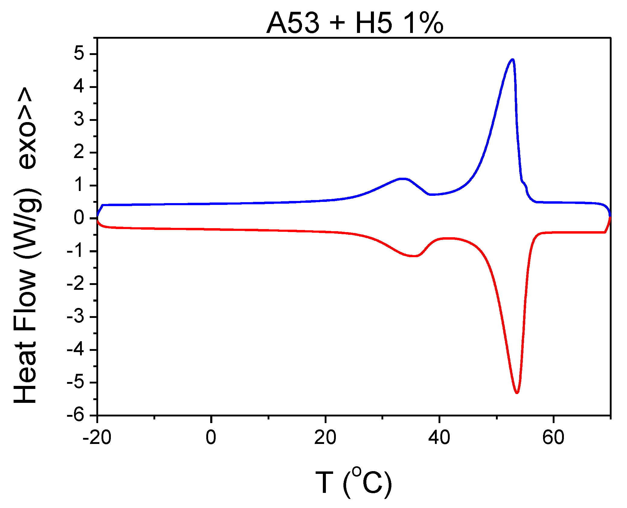
Paraffin with a melting temperature of 53 °C was provided by PCM Products Ltd. (Peterborough, UK), and graphite nanoplatelets (xGnP) were provided by XG Sciences, Inc. (Lansing, Michigan, USA) Graphite nanoplatelets are ultrathin particles of graphite that can also be thought of as short stacks of graphene sheets made with thicknesses beginning at a few nanometers and diameters ranging up from a few microns. In this study, we obtained data for three different types of nanoplatelets: grade M (thickness of 6–8 nm, diameter of 5 μm (M5) and diameter of 15 μm (M15) and typical surface area of 120 to 150 m2/g) and grade H (thickness of 15 nm, diameter of 5 μm (H5), and typical surface area of 50–80 m2/g). Details about the physical properties and images of the nanoparticles can be found in the corresponding datasheets from the manufacturer [75]. A typical DSC curve referring to A53 + H5 0.01 mass fraction is depicted in Figure 1. Finally, we also report on nanoplatelets (grade C) that typically consist of aggregates of sub-micron platelets with a particle diameter of less than two microns, thickness of a few nanometers (C750), and a surface area of 750 m2/g.
2.1. NP-Enhanced PCM Preparation
Paraffin wax was melted at 70 °C, and the nanoplatelets were added to the liquid paraffin by stirring at 0.005, 0.01, 0.02, 0.03, 0.04 and 0.06 mass fractions. The liquid composite was magnetically stirred for 30 min at a rotation speed of 250 rpm while the temperature was kept constant. When discussing the thermal properties of enhanced phase change materials in the literature, both mass and volume fractions are used. In order to facilitate comparisons, the conversion between the volume and mass fractions for a two-component system is given below (Equation (1)):
where ρm = 914 kg/m3 and ρd = 2200 kg/m3 are the densities of the paraffin matrix and the dispersed component, respectively; and ϕvol and ϕwt denote the volume and mass fractions, respectively.
2.2. Thermal Conductivity Measurements
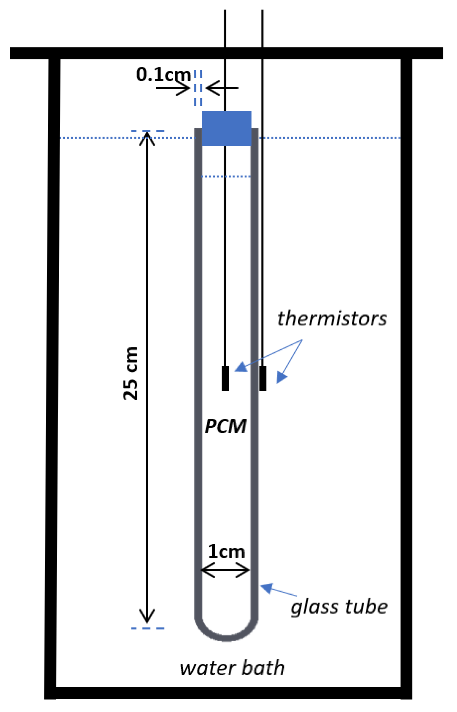
For the thermal conductivity measurement, we used a modified enthalpy-based water bath method, described in details elsewhere [76]. In contrast to the T-history method, we used only one cylindrical tube with a length of 25 cm, an external diameter of 1.2 cm, and a thickness of 1 mm. A schematic representation of the experimental setup is shown in Figure 2. The tube was borosilicate glass (Schott Duran®), with a thermal conductivity of 1.2 W/mK at 90 °C and a density of 2.23 g/cm3. The specific heat of the tube (not provided from the producer) was evaluated as a weighted average of the specific heat of its constituents, i.e., 81% SiO2, 13% B2O3, 4% Na2O + K2O, and 2% Al2O3. Two 5 mm NTC Thermistors of 14 Kohms each (Mouser Electronics, Inc., Buckinghamshire, UK) were used for the temperature measurements. One was placed at the center of the tube containing the PCM composite, and the second one was attached to the tube’s external surface. The temperature was obtained with an MCC USB data acquisition card. The tube with the PCM was initially equilibrated in a water bath of a certain temperature (well above the melting point) and was subsequently immersed into a cold water bath with a constant temperature of 10 °C. Taking into account the geometry of the tube, i.e., that its length was approximately 20 times longer than its diameter, we assumed that we were dealing with 1-dimensional transient heat conduction problems in cylindrical coordinates. By using a non-linear minimization procedure, the thermal conductivity could be evaluated by adjusting the numerical predictions with the experimental data [76].
2.3. Specific Heat Capacity and Heat of Fusion
The specific heat capacity and heat of fusion were measured with modulated differential scanning calorimetry (MDSC). MDSC differs from standard DSC in that it uses two simultaneous heating rates: a linear heating rate that provides information similar to standard DSC and a sinusoidal or modulated heating rate that permits the simultaneous measurement of the sample’s heat capacity.
3. Results and Discussion
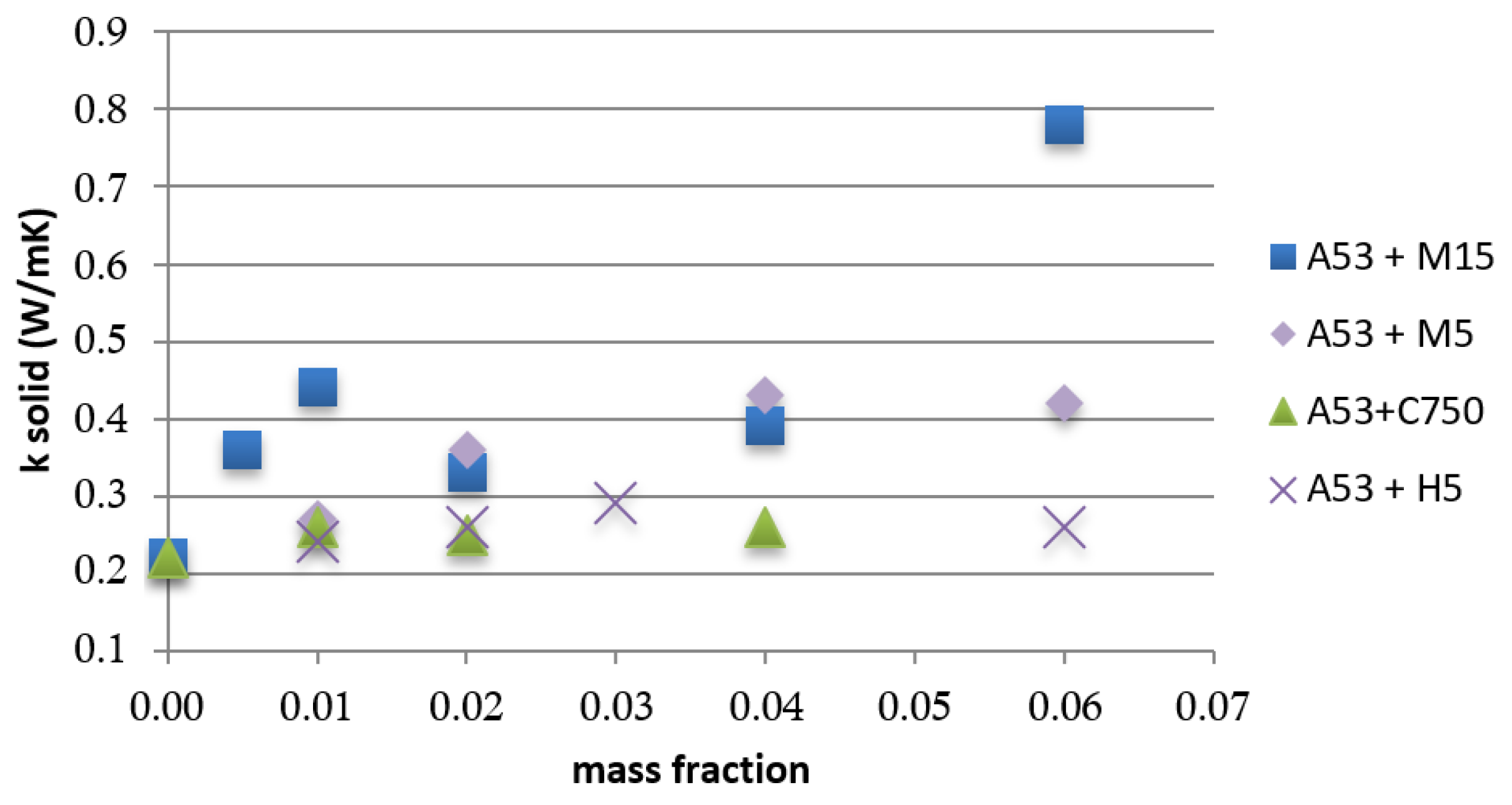
The measured thermal conductivities as a function of mass fraction of the various graphite nanoplatelets can be seen in Figure 3. The accuracy of the thermal conductivity values was calculated to the second decimal point, while the uncertainty evaluated at ±0.03 was obtained from the standard deviation of the measured values of 27 individual samples. There was an overall increase in thermal conductivity upon the addition of the nanoplatelets, although the effect was not linear, and it was different for each particular type of nanoparticle. The largest increase was seen in the M15 sample in the low mass fraction regime up to 0.01 and at 0.06 mass fractions. The thermal conductivity increased by 100% to the value of 0.44 W/mK from the 0.22 W/mK for pure paraffin with a 0.01 mass fraction (~0.004 volume fraction) and almost 250% with a 0.06 mass fraction (~0.026 volume fraction). The thermal conductivity did not increase linearly, most probably due to the interfacial resistance upon reaching the percolation threshold. The increase observed though is similar to that found in the literature for a similar-sized graphite nanoplatelets with a 15 μm diameter [1,74]. Samples M5 and M15 differed only in diameter; sample H5 had the same diameter as M5, but it had a smaller overall surface area. Samples with M5 also showed a significant increase in the thermal conductivity of the order of 60% to 100% for mass fractions between 0.02 and 0.06 (~0.008 and 0.0025 volume fraction). The composite with C750, the nanoplatelets with smaller size, more spherical shapes, and larger surface areas had less of an effect on thermal conductivity than the other composites, showing a small increase of ~13% that was rather constant for the whole range studied. At the higher end studied, for a 0.06 mass fraction (~0.025 volume fraction) for samples M5 and H5, the enhancement leveled off or reduced in contrast to M15, in which the thermal conductivity markedly enhanced. We note here that no significant changes were found in the melting points (<1 °C) of the nanofluids.
Figure 4 depicts thermal conductivity as a function of volume fraction in a preliminary effort to compare with effective-medium models for thermal conductivity of two-component composites.
Maxwell assumed spherical, non-interacting nanoparticles without any interfacial resistance between the matrix and nanoparticles. The following formula was derived for the effective conductivity of two-component composite materials (Equation (2)):
where ϕ is the volume fraction of the suspended medium and δ = kd/km is the ratio of the conductivities. Although valid for low-volume, very dilute dispersion, it was also shown to be applicable in dilutions of up to 0.1–0.20 volume fractions when δ >> 1 [66]. Figure 4 demonstrates that the Maxwell model underestimated the thermal conductivity in all cases except the more spherically shaped C750.
Nan et al. [77,78] proposed an effective-medium model based on carbon nanotubes and a matrix in which the effects of the aspect ratio of spheroidal particles and thermal interface resistance are included. Xiang and Drzal [79] adopted Nan’s EMT model for exfoliated expanded graphite nanoplatelets (xGnP, similar to the ones studied here) with a diameter of 15 μm and a thickness of 15 nm, and they found that the model fit their data. According to the model, the thermal conductivity ratio (Ke/Km) of isotropically oriented ellipsoidal particles can be expressed by (Equation (3)):
where Ke is the conductivity of the composite, Km is the matrix thermal conductivity, and ϕ is the volume fraction of graphite nanoplatelets. The thermal conductivities along the transverse and longitudinal axes of the graphite nanoplatelet ( and , respectively) can be expressed as (Equation (4)):
where t and d are the thickness and diameter, respectively, of the xGnP; and αk is the Kapitza radius defined by αk = RkKm, with Rk as the interface resistance. The thermal interface resistance at the boundary of graphite and paraffin was estimated using Nan’s model by Xiang and Drzal [79] as 7–8 × 10⁻⁸ m2 K/W, a value that is very close to the interfacial resistance of 8.2 × 10⁻⁸ m2 K/W across the carbon nanotube water matrix reported by Huxtable et al. [80].
Following Nan et al. [78] and Xiang et al. [79], we assumed that the nanoplatelet was coated with a thin, interfacial thermal barrier layer with a Kapitza radius defined by the estimated value of the thermal interface resistance (Rk = 8.2 × 10⁻⁸ m2 K/W). Figure 4 shows the resultant theoretical prediction for the different sizes, aspect ratios, and experimental data. Samples with M5 nanoparticles seemed to be a better fit than samples with M15. The model overestimated the thermal conductivity of samples with H5 nanoplatelets, especially at higher mass fractions. The two types, M and H, differed in overall surface area due to the method of preparation, with M15 and M5 having larger surface areas than H5. Direct comparison between samples with M5 and H5, which had the same diameter, suggested that larger surface area led to increased thermal conductivity. However, the C750 samples, which had the largest surface area, showed the smallest increase, suggesting that the effects of shape anisotropy and higher aspect ratio were more important factors than surface area. The effect of surface area is not clear at this time, and more data would be required to reach a sound conclusion. In addition, it should be noted that a large amount of uncertainty arises from the accuracy of the reported particle shape and size. Reported data in this study were taken from the manufacturer’s nominal information and were not measured directly.
For samples with M15 nanoplatelets, the model underestimated the thermal conductivity in the low mass fraction regime, and it overestimated it above a 0.01 volume fraction. It should be noted that the model may not be valid for the whole range studied, especially for the longer M15 nanoparticles, as it assumes isolated nanoparticles. However, evidence from electrical measurements of paraffin/xGnP composites of similar sizes suggests that a percolation conductive path was formed at as low as with a 0.01 volume fraction for a 15 μm diameter nanoplatelet. No evidence of percolation was found at a 0.02 volume fraction for smaller-diameter nanoplatelets of 1 μm [79]. Perhaps, this may account for the better fit for the samples with M5 nanoplatelets as well as the increased thermal conductivity of the longer nanoparticles at the low mass fractions.
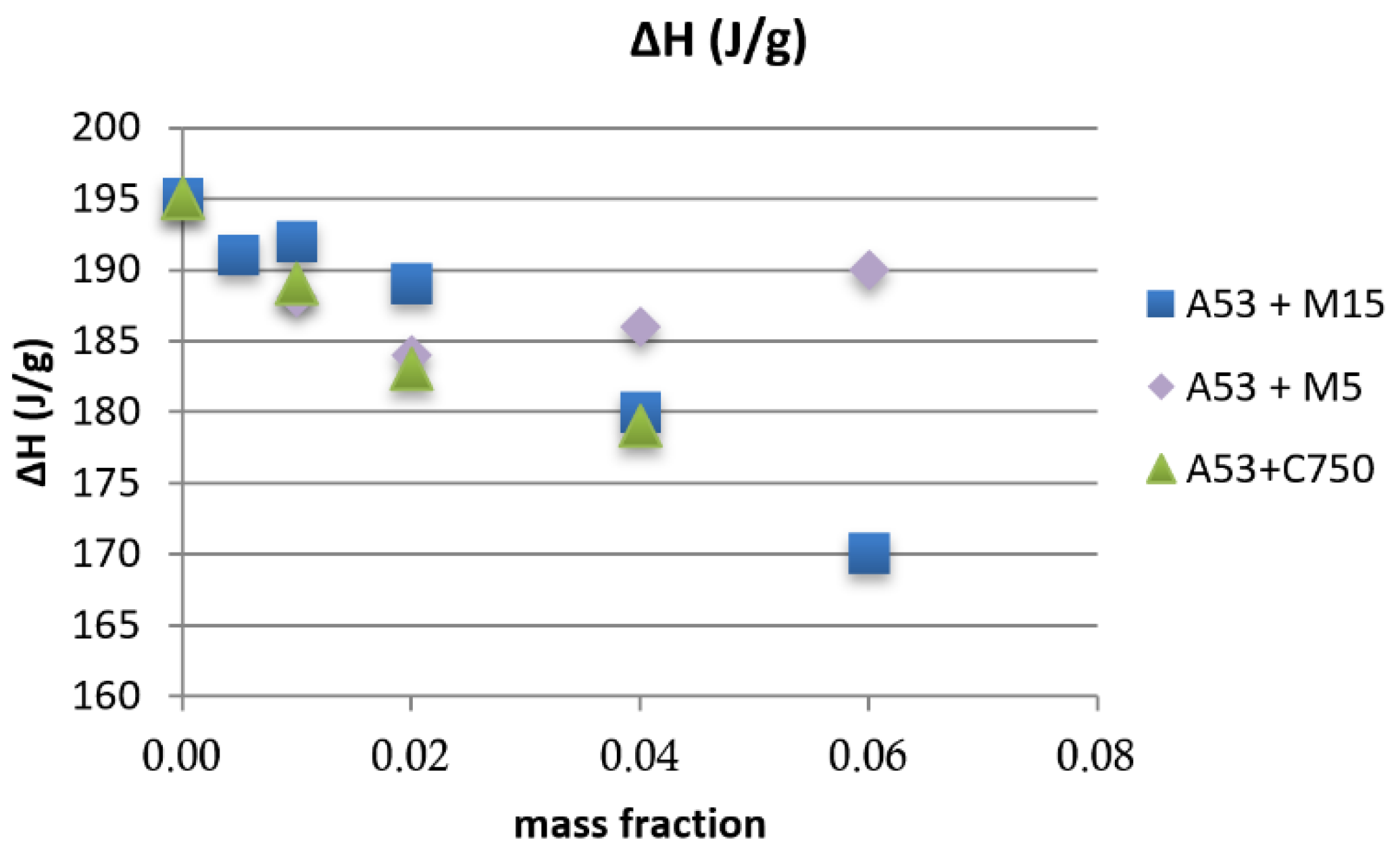
In Figure 5, the heat of fusion is shown as a function of mass fraction for the different nanoplatelets. It can be seen that thermal conductivity for the small mass fraction of 0.01 in the M15 samples increased by 100%, and the heat of fusion reduced only slightly (~2%). The heat of fusion gradually reduced with the increase in mass fraction to about 10% for a 0.06 mass fraction. A similar trend was seen for the samples with C750 nanoplatelets. Interestingly, the M5 nanoplatelets seemed to leave the heat of fusion largely unaffected up to a 0.06 mass fraction.
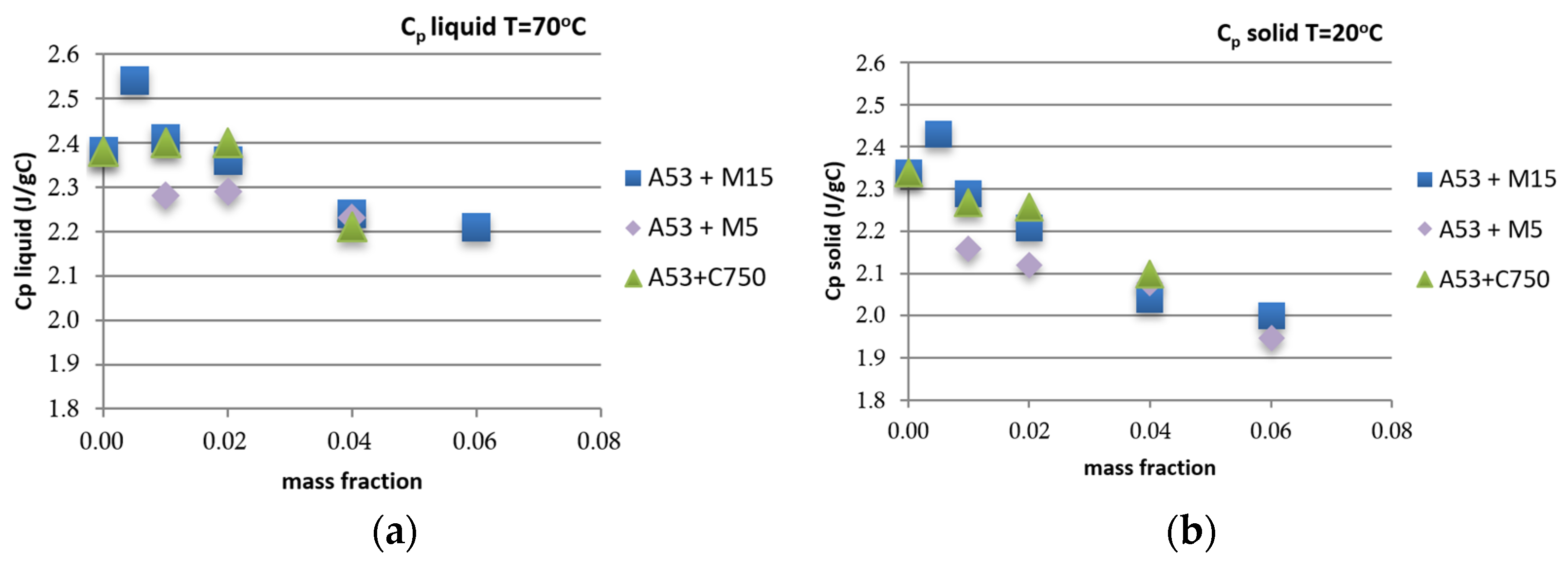
Similarly, the specific heat capacitance Cp (Figure 6) showed negligible change as a function of mass fraction for the liquid phase of the M15 sample at a 0.01 mass fraction. In the solid phase, the respective change was 0.02 with a 0.01 mass concentration, which increased to 14% at the maximum mass fraction studied.
4. Conclusions
In conclusion, we performed an extensive study on various types of nanoparticle additions to wax-based PCMs with the aim of exploring the possibility of increasing their thermal conductivity while preserving unaffected their latent and specific heat. We tested several types of nanoparticles, including metals, oxides, semiconductors, and carbon-based nano-additives. Our results showed that nanoplatelets composed of expanded graphite mixed in paraffin increased thermal conductivity at relatively low mass concentrations (0.01 and 0.06 mass fractions). In particular, we found that graphite nanoparticle additions at the above fractions with a diameter of 15 µm and thickness of 6–8 nm increased the thermal conductivity by 100% to 250%, respectively. Additionally, the heat of fusion was only slightly reduced from 2–10% for the 0.01 and 0.06 mass fractions, respectively. These results provide an efficient and easy way to improving the thermal properties of PCMs, rendering them suitable for thermal storage applications.
Author Contributions
Conceptualization, G.A.E. and M.T.; methodology, G.A.E. and I.E.L.; software, D.G.P., G.A.E. and I.E.L.; validation, C.P., D.G.P. and G.A.E.; formal analysis, I.E.L., G.A.E. and M.T.; writing, M.T. and G.A.E. All authors have read and agreed to the published version of the manuscript.
Funding
This work was supported by the TESSe2b project, which received funding from the European Union’s Research and Innovation Program, Horizon 2020, under grant agreement No 680555.
Data Availability Statement
Contact person: [email protected].
Conflicts of Interest
The authors declare no conflict of interest.
References
- Xia, L.; Zhang, P.; Wang, R. Preparation and thermal characterization of expanded graphite/paraffin composite phase change material. Carbon 2010, 48, 2538–2548. [Google Scholar] [CrossRef]
- Choi, S.U.S.; Eastman, J.A. Enhancing Thermal Conductivity of Fluids with Nanoparticles; Argonne National Lab.: Lemont, IL, USA, 1995. [Google Scholar]
- Gupta, M.; Singh, V.; Kumar, R.; Said, Z. A review on thermophysical properties of nanofluids and heat transfer applications. Renew. Sustain. Energy Rev. 2017, 74, 638–670. [Google Scholar] [CrossRef]
- Azmi, W.; Sharma, K.; Mamat, R.; Najafi, G.; Mohamad, M. The enhancement of effective thermal conductivity and effective dynamic viscosity of nanofluids–A review. Renew. Sustain. Energy Rev. 2016, 53, 1046–1058. [Google Scholar] [CrossRef]
- Elsheikh, A.; Sharshir, S.; Mostafa, M.E.; Essa, F.; Ali, M.K.A. Applications of nanofluids in solar energy: A review of recent advances. Renew. Sustain. Energy Rev. 2018, 82, 3483–3502. [Google Scholar] [CrossRef]
- Akram, N.; Sadri, R.; Kazi, S.N.; Zubir, M.N.M.; Ridha, M.; Ahmed, W.; Soudagar, M.E.M.; Arzpeyma, M. A comprehensive review on nanofluid operated solar flat plate collectors. J. Therm. Anal. 2019, 139, 1309–1343. [Google Scholar] [CrossRef]
- Zayed, M.; Zhao, J.; Du, Y.; Kabeel, A.; Shalaby, S. Factors affecting the thermal performance of the flat plate solar collector using nanofluids: A review. Sol. Energy 2019, 182, 382–396. [Google Scholar] [CrossRef]
- Suganthi, K.; Rajan, K. Metal oxide nanofluids: Review of formulation, thermo-physical properties, mechanisms, and heat transfer performance. Renew. Sustain. Energy Rev. 2017, 76, 226–255. [Google Scholar] [CrossRef]
- Sharma, S.K.; Gupta, S.M. Preparation and evaluation of stable nanofluids for heat transfer application: A review. Exp. Therm. Fluid Sci. 2016, 79, 202–212. [Google Scholar]
- Arthur, O.; Karim, A. An investigation into the thermophysical and rheological properties of nanofluids for solar thermal applications. Renew. Sustain. Energy Rev. 2016, 55, 739–755. [Google Scholar] [CrossRef] [Green Version]
- Sundar, L.; Singh, M.K.; Veeraboina, P.; Sousa, A. Experimental investigation of Al2O3/water nanofluids on the effectiveness of solar flat-plate collectors with and without twisted tape inserts. Renew. Energy 2017, 119, 820–833. [Google Scholar] [CrossRef]
- Mirzaei, M.; Hosseini, S.M.S.; Kashkooli, A.M.M. Assessment of Al2O3 nanoparticles for the optimal operation of the flat plate solar collector. Appl. Therm. Eng. 2018, 134, 68–77. [Google Scholar] [CrossRef]
- Hajabdollahi, F.; Premnath, K. Numerical study of the effect of nanoparticles on thermoeconomic improvement of a solar flat plate collector. Appl. Therm. Eng. 2017, 127, 390–401. [Google Scholar] [CrossRef]
- Genc, A.M.; Ezan, M.A.; Turgut, A. Thermal performance of a nanofluid-based flat plate solar collector: A transient numerical study. Appl. Therm. Eng. 2018, 130, 395–407. [Google Scholar] [CrossRef]
- Moghadam, M.C.; Edalatpour, M.; Solano, J.P. Numerical Study on Conjugated Laminar Mixed Convection of Alumina/Water Nanofluid Flow, Heat Transfer, and Entropy Generation Within a Tube-on-Sheet Flat Plate Solar Collector. J. Sol. Energy Eng. 2017, 139, 041011. [Google Scholar] [CrossRef]
- Edalatpour, M.; Solano, J.P. Thermal-hydraulic characteristics and exergy performance in tube-on-sheet flat plate solar collectors: Effects of nanofluids and mixed convection. Int. J. Therm. Sci. 2017, 118, 397–409. [Google Scholar] [CrossRef]
- Shojaeizadeh, E.; Veysi, F.; Kamandi, A. Exergy efficiency investigation and optimization of an Al2O3–water nanofluid based Flat-plate solar collector. Energy Build. 2015, 101, 12–23. [Google Scholar] [CrossRef]
- Hussain, M.Y.; Ali, H.; Aneeq, M.; Sheikh, K.A.; Rehman, S. Optical and Thermal Analysis of a Flat Plate Solar Collector Using Water and Alumina Nano Fluids. In Proceedings of the 2019 International Conference on Applied and Engineering Mathematics (ICAEM), Taxila, Pakistan, 27–29 August 2019. [Google Scholar]
- Said, Z.; Saidur, R.; Rahim, N. Energy and exergy analysis of a flat plate solar collector using different sizes of aluminium oxide based nanofluid. J. Clean. Prod. 2016, 133, 518–530. [Google Scholar] [CrossRef]
- Said, Z.; Saidur, R.; Sabiha, M.; Hepbasli, A.; Rahim, N. Energy and exergy efficiency of a flat plate solar collector using pH treated Al2O3 nanofluid. J. Clean. Prod. 2016, 112, 3915–3926. [Google Scholar] [CrossRef]
- Colangelo, G.; Favale, E.; de Risi, A.; Laforgia, D. A new solution for reduced sedimentation flat panel solar thermal collector using nanofluids. Appl. Energy 2013, 111, 80–93. [Google Scholar] [CrossRef]
- Hawwash, A.; Rahman, A.K.A.; Nada, S.; Ookawara, S. Numerical Investigation and Experimental Verification of Performance Enhancement of Flat Plate Solar Collector Using Nanofluids. Appl. Therm. Eng. 2018, 130, 363–374. [Google Scholar] [CrossRef]
- Sint, N.K.C.; Choudhury, I.A.; Masjuki, H.H.; Aoyama, H. Theoretical analysis to determine the efficiency of a CuO-water nanofluid based-flat plate solar collector for domestic solar water heating system in Myanmar. Sol. Energy 2017, 155, 608–619. [Google Scholar] [CrossRef]
- Moghadam, A.J.; Farzaneh-Gord, M.; Sajadi, M.; Hoseyn-Zadeh, M. Effects of CuO/water nanofluid on the efficiency of a flat-plate solar collector. Exp. Therm. Fluid Sci. 2014, 58, 9–14. [Google Scholar] [CrossRef]
- Michael, J.J.; Iniyan, S. Performance of copper oxide/water nanofluid in a flat plate solar water heater under natural and forced circulations. Energy Convers. Manag. 2015, 95, 160–169. [Google Scholar] [CrossRef]
- Owolabi, A.L.; Al-Kayiem, H.H.; Baheta, A.T. Performance investigation on a thermal energy storage integrated solar collector system using nanofluid. Int. J. Energy Res. 2016, 41, 650–657. [Google Scholar] [CrossRef]
- Verma, S.K.; Tiwari, A.K.; Chauhan, D.S. Performance augmentation in flat plate solar collector using MgO/water nanofluid. Energy Convers. Manag. 2016, 124, 607–617. [Google Scholar] [CrossRef]
- Amini, M.; Kianifar, A. An analytical study on energy and exergy of a minichannel-based solar collector using Fe3O4 and MgOwater nanofluids. In Proceedings of the International Conference on researches in Science and Engineering, Istambul, Turkey, 28 July 2016. [Google Scholar]
- Tomy, A.M.; Ahammed, N.; Subathra, M.; Asirvatham, L.G. Analysing the Performance of a Flat Plate Solar Collector with Silver/Water Nanofluid Using Artificial Neural Network. Procedia Comput. Sci. 2016, 93, 33–40. [Google Scholar] [CrossRef] [Green Version]
- Lazarus, G.; Roy, S.; Kunhappan, D.; Cephas, E.; Wongwises, S. Heat transfer performance of silver/water nanofluid in a solar flat-plate collector. J. Therm. Eng. 2015, 1, 104. [Google Scholar] [CrossRef]
- Said, Z.; Sabiha, M.; Saidur, R.; Hepbasli, A.; Rahim, N.; Mekhilef, S.; Ward, T. Performance enhancement of a Flat Plate Solar collector using Titanium dioxide nanofluid and Polyethylene Glycol dispersant. J. Clean. Prod. 2015, 92, 343–353. [Google Scholar] [CrossRef]
- Kılıç, F.; Menlik, T.; Sözen, A. Effect of titanium dioxide/water nanofluid use on thermal performance of the flat plate solar collector. Sol. Energy 2018, 164, 101–108. [Google Scholar] [CrossRef]
- Chaji, H.; Ajabshirchi, Y.; Esmaeilzadeh, E.; Heris, S.; Hedayatizadeh, M.; Kahani, M. Experimental study on thermal efficiency of flat plate solar collector using TiO2/water nanofluid. Mod. Appl. Sci. 2013, 7, 60–69. [Google Scholar] [CrossRef]
- Sharafeldin, M.; Gróf, G. Experimental investigation of flat plate solar collector using CeO2 -water nanofluid. Energy Convers. Manag. 2018, 155, 32–41. [Google Scholar] [CrossRef]
- Michael Joseph Stalin, P.; Arjunan, T.V.; Matheswaran, M.M.; Sadanandam, N. Experimental and theoretical investigation on the effects of lower concentration CeO2/water nanofluid in flat-plate solar collector. J. Therm. Anal. Calorim. 2019, 135, 29–44. [Google Scholar] [CrossRef]
- Jahanshahi, M.; Hosseinizadeh, S.; Alipanah, M.; Dehghani, A.; Vakilinejad, G. Numerical simulation of free convection based on experimental measured conductivity in a square cavity using Water/SiO2 nanofluid. Int. Commun. Heat Mass Transf. 2010, 37, 687–694. [Google Scholar] [CrossRef]
- Noghrehabadi, A.; Hajidavalloo, E.; Moravej, M. Experimental investigation of efficiency of square flat-plate solar collector using SiO2/water nanofluid. Case Stud. Therm. Eng. 2016, 8, 378–386. [Google Scholar] [CrossRef] [Green Version]
- Salavati Meibodi, S.; Kianifar, A.; Niazmand, H.; Mahian, O.; Wongwises, S. Experimental investigation on the thermal efficiency and performance characteristics of a flat plate solar collector using SiO2/EG–water nanofluids. Int. Commun. Heat Mass Transf. 2015, 65, 71–75. [Google Scholar] [CrossRef]
- Javaniyan, H.; Saedodin, S.; Zamzamian, S.A.; Eshagh Nimvari, M.; Wongwises, S. Effects of porous material and nanoparticles on the thermal performance of a flat plate solar collector: An experimental study. Renew. Energy 2017, 114, 1407–1418. [Google Scholar]
- Faizal, M.; Saidur, R.; Mekhilef, S.; Hepbasli, A.; Mahbubul, I.M. Energy, economic, and environmental analysis of a flat-plate solar collector operated with SiO2 nanofluid. Clean Technol. Environ. Policy 2015, 17, 1457–1473. [Google Scholar] [CrossRef] [Green Version]
- Mahian, O.; Kianifar, A.; Sahin, A.Z.; Wongwises, S. Heat Transfer, Pressure Drop, and Entropy Generation in a Solar Collector Using SiO2/Water Nanofluids: Effects of Nanoparticle Size and pH. J. Heat Transf. 2015, 137, 061011. [Google Scholar] [CrossRef]
- Borode, A.; Ahmed, N.; Olubambi, P. A review of solar collectors using carbon-based nanofluids. J. Clean. Prod. 2019, 241, 118311. [Google Scholar] [CrossRef]
- Ahmadi, A.; Ganji, D.D.; Jafarkazemi, F. Analysis of utilizing Graphene nanoplatelets to enhance thermal performance of flat plate solar collectors. Energy Convers. Manag. 2016, 126, 1–11. [Google Scholar] [CrossRef]
- Vincely, D.A.; Natarajan, E. Experimental investigation of the solar FPC performance using graphene oxide nanofluid under forced circulation. Energy Convers. Manag. 2016, 117, 1–11. [Google Scholar] [CrossRef]
- Vakili, M.; Hosseinalipour, S.; Delfani, S.; Khosrojerdi, S.; Karami, M. Experimental investigation of graphene nanoplatelets nanofluid-based volumetric solar collector for domestic hot water systems. Sol. Energy 2016, 131, 119–130. [Google Scholar] [CrossRef]
- Said, Z.; Saidur, R.; Sabiha, M.; Rahim, N.; Anisur, M. Thermophysical properties of Single Wall Carbon Nanotubes and its effect on exergy efficiency of a flat plate solar collector. Sol. Energy 2015, 115, 757–769. [Google Scholar] [CrossRef]
- Said, Z.; Saidur, R.; Rahim, N.; Alim, M. Analyses of exergy efficiency and pumping power for a conventional flat plate solar collector using SWCNTs based nanofluid. Energy Build. 2014, 78, 1–9. [Google Scholar] [CrossRef]
- Yousefi, T.; Shojaeizadeh, E.; Veysi, F.; Zinadini, S. An experimental investigation on the effect of pH variation of MWCNT–H2O nanofluid on the efficiency of a flat-plate solar collector. Sol. Energy 2011, 86, 771–779. [Google Scholar] [CrossRef]
- Verma, S.K.; Tiwari, A.K.; Tiwari, S.; Chauhan, D.S. Performance analysis of hybrid nanofluids in flat plate solar collector as an advanced working fluid. Sol. Energy 2018, 167, 231–241. [Google Scholar] [CrossRef]
- Nasrin, R.; Alim, M.A. Finite Element Simulation of Forced Convection in a Flat Plate Solar Collector: Influence of Nanofluid with Double Nanoparticles. J. Appl. Fluid Mech. 2014, 7, 543–556. [Google Scholar]
- Hajabdollahi, Z.O.; Mirzaei, M.; Kim, K.C.; Ouderji, Z.H. Effects of a Mixture of Cuo and Al2O3 Nanoparticles on the Thermal Efficiency of a Flat Plate Solar Collector at Different Mass Flow Rates. Heat Transf. Res. 2019, 50, 945–965. [Google Scholar] [CrossRef]
- Menni, Y.; Chamkha, A.J.; Massarotti, N.; Ameur, H.; Kaid, N.; Bensafi, M. Hydrodynamic and thermal analysis of water, ethylene glycol and water-ethylene glycol as base fluids dispersed by aluminum oxide nano-sized solid particles. Int. J. Numer. Methods Heat Fluid Flow 2020, 30, 4349–4386. [Google Scholar] [CrossRef]
- Zamzamian, S.A.; KeyanpourRad, M.; KianiNeyestani, M.; Jamal-Abad, M. An experimental study on the effect of Cu-synthesized/EG nanofluid on the efficiency of flat-plate solar collectors. Renew. Energy 2014, 71, 658–664. [Google Scholar] [CrossRef]
- Farhana, K.; Kadirgama, K.; Rahman, M.; Ramasamy, D.; Noor, M.; Najafi, G.; Samykano, M.; Mahamude, A. Improvement in the performance of solar collectors with nanofluids — A state-of-the-art review. Nano-Structures Nano-Objects 2019, 18, 100276. [Google Scholar] [CrossRef]
- Khodadadi, J.; Fan, L.; Babaei, H. Thermal conductivity enhancement of nanostructure-based colloidal suspensions utilized as phase change materials for thermal energy storage: A review. Renew. Sustain. Energy Rev. 2013, 24, 418–444. [Google Scholar] [CrossRef]
- Kibria, M.; Anisur, M.; Mahfuz, M.; Saidur, R.; Metselaar, H.S.C. A review on thermophysical properties of nanoparticle dispersed phase change materials. Energy Convers. Manag. 2015, 95, 69–89. [Google Scholar] [CrossRef] [Green Version]
- Keblinski, P.; Phillpot, S.; Choi, S.; Eastman, J. Mechanisms of heat flow in suspensions of nano-sized particles (nanofluids). Int. J. Heat Mass Transf. 2002, 45, 855–863. [Google Scholar] [CrossRef]
- Prasher, R.; Evans, W.; Meakin, P.; Fish, J.; Phelan, P.; Keblinskia, P. Effect of aggregation on thermal conduction in colloidal nanofluids. Appl. Phys. Lett. 2006, 89, 143119. [Google Scholar] [CrossRef] [Green Version]
- Gharagozloo, P.E.; Eaton, J.K.; Goodson, K.E. Diffusion, aggregation, and the thermal conductivity of nanofluids. Appl. Phys. Lett. 2008, 93, 103110. [Google Scholar] [CrossRef] [Green Version]
- Bonnet, P.; Sireude, D.; Garnier, B.; Chauvet, O. Thermal properties and percolation in carbon nanotube-polymer composites. Appl. Phys. Lett. 2007, 91, 201910. [Google Scholar] [CrossRef]
- Murshed, S.; Leong, K.C.; Yang, C. Thermophysical and electrokinetic properties of nanofluids – A critical review. Appl. Therm. Eng. 2008, 28, 2109–2125. [Google Scholar] [CrossRef]
- Murshed, S.M.S.; Leong, K.C.; Yang, C. Enhanced thermal conductivity of TiO2—water based nanofluids. Int. J. Therm. Sci. 2005, 44, 367–373. [Google Scholar] [CrossRef]
- Zhu, H.; Zhang, C.; Liu, S.; Tang, Y.; Yin, Y. Effects of nanoparticle clustering and alignment on thermal conductivities of Fe3O4 aqueous nanofluids. Appl. Phys. Lett. 2006, 89, 023123. [Google Scholar] [CrossRef]
- Timofeeva, E.V.; Routbort, J.L.; Singh, D. Particle shape effects on thermophysical properties of alumina nanofluids. J. Appl. Phys. 2009, 106, 014304. [Google Scholar] [CrossRef]
- Deng, F.; Zheng, Q.-S.; Wang, L.; Nan, C.-W. Effects of anisotropy, aspect ratio, and nonstraightness of carbon nanotubes on thermal conductivity of carbon nanotube composites. Appl. Phys. Lett. 2007, 90, 021914. [Google Scholar] [CrossRef]
- Cherkasova, A.S.; Shan, J.W. Particle Aspect-Ratio Effects on the Thermal Conductivity of Micro- and Nanoparticle Suspensions. J. Heat Transf. 2008, 130, 082406. [Google Scholar] [CrossRef]
- Xie, S.H.; Liu, Y.Y.; Li, J. Comparison of the effective conductivity between composites reinforced by graphene nanosheets and carbon nanotubes. Appl. Phys. Lett. 2008, 92, 243121. [Google Scholar] [CrossRef]
- Yu, W.; France, D.M.; Routbort, J.L.; Choi, S.U.S. Review and Comparison of Nanofluid Thermal Conductivity and Heat Transfer Enhancements. Heat Transf. Eng. 2008, 29, 432–460. [Google Scholar] [CrossRef]
- Kim, B.-W.; Park, S.-H.; Kapadia, R.S.; Bandaru, P.R. Evidence of percolation related power law behavior in the thermal conductivity of nanotube/polymer composites. Appl. Phys. Lett. 2013, 102, 243105. [Google Scholar] [CrossRef]
- Shehzad, K.; Ahmad, M.N.; Hussain, T.; Mumtaz, M.; Shah, A.T.; Mujahid, A.; Wang, C.; Ellingsen, J.; Dang, Z.-M. Influence of carbon nanotube dimensions on the percolation characteristics of carbon nanotube/polymer composites. J. Appl. Phys. 2014, 116, 064908. [Google Scholar] [CrossRef]
- Warzoha, R.J.; Rao, A.; Weigand, R.; Fleischer, A.S. Experimental Characterization of the Thermal Diffusivity of Paraffin Phase Change Material Embedded With Herringbone Style Graphite Nanofibers. In Proceedings of the ASME 2012 Heat Transfer Summer Conference collocated with the ASME 2012 Fluids Engineering Division Summer Meeting and the ASME 2012 10th International Conference on Nanochannels, Microchannels, and Minichannels, Rio Grande, Puerto Rico, 8–12 July 2012. [Google Scholar]
- Zeng, J.L.; Liu, Y.Y.; Cao, Z.X.; Zhang, J.; Zhang, Z.H.; Sun, L.X.; Xu, F. Thermal conductivity enhancement of MWNTs on the PANI/tetradecanol form-stable PCM. J. Therm. Anal. 2007, 91, 443–446. [Google Scholar] [CrossRef]
- Li, M. A nano-graphite/paraffin phase change material with high thermal conductivity. Appl. Energy 2013, 106, 25–30. [Google Scholar] [CrossRef]
- Kim, S.; Drzal, L.T. High latent heat storage and high thermal conductive phase change materials using exfoliated graphite nanoplatelets. Sol. Energy Mater. Sol. Cells 2009, 93, 136–142. [Google Scholar] [CrossRef]
- XGSciences. Available online: https://xgsciences.com/graphene/ (accessed on 29 December 2021).
- Evangelakis, G.A.; Lagaris, I.; Papageorgiou, D.G.; Prouskas, K.; Zisopoulou, A. A Hybrid Numerical-Experimental Method for Determining Thermal Conductivities. J. Heat Transf. 2020, 143. [Google Scholar] [CrossRef]
- Nan, C.-W.; Birringer, R.; Clarke, D.; Gleiter, H. Effective thermal conductivity of particulate composites with interfacial thermal resistance. J. Appl. Phys. 1997, 81, 6692–6699. [Google Scholar] [CrossRef]
- Nan, C.-W.; Liu, G.; Lin, Y.; Li, M. Interface effect on thermal conductivity of carbon nanotube composites. Appl. Phys. Lett. 2004, 85, 3549–3551. [Google Scholar] [CrossRef]
- Xiang, J.; Drzal, L.T. Investigation of exfoliated graphite nanoplatelets (xGnP) in improving thermal conductivity of paraffin wax-based phase change material. Sol. Energy Mater. Sol. Cells 2011, 95, 1811–1818. [Google Scholar] [CrossRef]
- Huxtable, S.T.; Cahill, D.G.; Shenogin, S.; Xue, L.; Ozisik, R.; Barone, P.; Usrey, M.; Strano, M.S.; Siddons, G.; Shim, M. Interfacial heat flow in carbon nanotube suspensions. Nat. Mater. 2003, 2, 731–734. [Google Scholar] [CrossRef] [PubMed]
Figure 1.
Typical DSC curve (A53 + H5 0.01 mass fraction).

Figure 2.
Experimental setup.

Figure 3.
Thermal conductivity of paraffin wax with graphite nanoplatelets as a function of mass fraction with different sizes, aspect ratios, and surface areas: squares, M15 (d = 15 μm, thickness = 6–8 nm, and surface area = 120–150 m2/g); rhombus, Μ5 (d = 5 μm, thickness = 6–8 nm, and surface area = 120–150 m2/g); crosses, H5 (d = 5 μm, thickness = 15 nm, and surface area = 50–80 m2/g); and triangle, C750 (d < 2 μm, thickness = a few nm, and surface area = 750 m2/g).

Figure 4.
Ratio of thermal conductivity of composite paraffin wax with graphite nanoplatelets to the thermal conductivity of paraffin as a function of volume fraction with different sizes, aspect ratios, and surface areas: squares, M15 (diameter = 15 μm, thickness = 6–8 nm, and surface area = 120–150 m2/g; diamonds, Μ5 (diameter = 5 μm, thickness = 6–8 nm, and surface area = 120–150 m2/g; crosses, H5 (diameter = 5 μm, thickness = 15 nm, and surface area = 50–80 m2/g); triangles, C750 (diameter < 2 μm, thickness = a few nm, and surface area = 750 m2/g). The straight grey line represents the theoretical prediction of the Maxwell–Eucken model, and the blue and yellow lines represent Nan’s EMT model [27] for the dimensions of M15 and H5, respectively, with Rk = 9 × 10⁻⁸ m2 K/W [29].

Figure 5.
Heat of fusion as a function of mass fraction of: squares, M15 (diameter = 15 μm, thickness = 6–8 nm, and surface area = 120–150 m2/g); rhombuses, Μ5 (diameter = 5 μm, thickness = 6–8 nm, and surface area = 120–150 m2/g), and triangles, C750 (diameter < 2 μm, thickness = a few nm, and surface area = 750 m2/g).

Figure 6.
Specific heat capacitance as a function of mass fraction of (a) liquid at 70 °C and (b) solid at 20 °C. Squares: M15; rhombuses: Μ5; triangles: C750.
Figure 6.
Specific heat capacitance as a function of mass fraction of (a) liquid at 70 °C and (b) solid at 20 °C. Squares: M15; rhombuses: Μ5; triangles: C750.

Publisher’s Note: MDPI stays neutral with regard to jurisdictional claims in published maps and institutional affiliations. |
© 2022 by the authors. Licensee MDPI, Basel, Switzerland. This article is an open access article distributed under the terms and conditions of the Creative Commons Attribution (CC BY) license (https://creativecommons.org/licenses/by/4.0/).
Share and Cite
MDPI and ACS Style
Tselepi, M.; Prouskas, C.; Papageorgiou, D.G.; Lagaris, I.E.; Evangelakis, G.A. Graphene-Based Phase Change Composite Nano-Materials for Thermal Storage Applications. Energies 2022, 15, 1192. https://doi.org/10.3390/en15031192
AMA Style
Tselepi M, Prouskas C, Papageorgiou DG, Lagaris IE, Evangelakis GA. Graphene-Based Phase Change Composite Nano-Materials for Thermal Storage Applications. Energies. 2022; 15(3):1192. https://doi.org/10.3390/en15031192
Chicago/Turabian StyleTselepi, Marina, Costas Prouskas, Dimitrios G. Papageorgiou, Isaac. E. Lagaris, and Georgios A. Evangelakis. 2022. "Graphene-Based Phase Change Composite Nano-Materials for Thermal Storage Applications" Energies 15, no. 3: 1192. https://doi.org/10.3390/en15031192
Note that from the first issue of 2016, this journal uses article numbers instead of page numbers. See further details here.