
A Low Latency Secure Communication Architecture for Microgrid Control


1
Department of Electronics and Embedded Systems, The Royal Institute of Technology (KTH), 114 28 Stockholm, Sweden
2
Department of Computer Science, Hekma School of Engineering, Computing, and Informatics, Dar Al-Hekma University, Jeddah 22246-4872, Saudi Arabia
3
Department of Computing, University of Turku, FI-20014 Turku, Finland
4
Higher Institute of Computer Sciences and Mathematics, Department of Technology, University of Monastir, Monastir 5000, Tunisia
5
College of Information and Communication Technologies, University of Dar es Salaam, Dar es Salaam 14113, Tanzania
*
Author to whom correspondence should be addressed.
Energies 2021, 14(19), 6262; https://doi.org/10.3390/en14196262
Submission received: 24 August 2021
/
Revised: 20 September 2021
/
Accepted: 26 September 2021
/
Published: 1 October 2021
Abstract
:The availability of secure, efficient, and reliable communication systems is critical for the successful deployment and operations of new power systems such as microgrids. These systems provide a platform for implementing intelligent and autonomous algorithms that improve the power control process. However, building a secure communication system for microgrid purposes that is also efficient and reliable remains a challenge. Conventional security mechanisms introduce extra processing steps that affect performance by increasing the latency of microgrid communication beyond acceptable limits. They also do not scale well and can impact the reliability of power operations as the size of a microgrid grows. This paper proposes a low latency secure communication architecture for control operations in an islanded IoT-based microgrid that solves these problems. The architecture provides a secure platform that optimises the standard CoAP/DTLS implementation to reduce communication latency. It also introduces a traffic scheduler component that uses a fixed priority preemptive algorithm to ensure reliability as the microgrid scales up. The architecture is implemented on a lab-scale IoT-based microgrid prototype to test for performance and security. Results show that the proposed architecture can mitigate the main security threats and provide security services necessary for power control operations with minimal latency performance. Compared to other implementations using existing secure IoT protocols, our secure architecture was the only one to satisfy and maintain the recommended latency requirements for power control operations, i.e., 100 ms under all conditions.
1. Introduction
Microgrids are small scale power systems that have shown the potential to solve the energy access problem in developing countries [1]. They allow off-grid communities to utilise locally available energy resources to generate affordable electricity for their needs. Microgrids offer an alternative approach to the conventional way of generating from large centralised sources. This speeds up the deployment rate and reduces the cost of supplying electricity in these poor communities [2]. Furthermore, with the integration of renewable energy resources such as solar and biomass, microgrids offer a clean way to generate electricity that is environmental-friendly [3].
One of the critical factors for the successful deployment and operation of a microgrid is a reliable and secure communication system [4,5,6]. The power generation process involves many systems, components, and processes that need to be coordinated together. A reliable communication system facilitates this process. It allows the implementation of autonomous algorithms that improve the efficiency of the power distribution process [7]. A secure communication system also protects the critical power system from potential threats that can disrupt operations [8]. This prevents damages and improves the stability of the whole system [9].
However, it is a challenge to build a communication system for microgrids that is reliable, efficient, and secure [10]. A communication system for microgrids needs to support the strict performance requirements of power protection, control, and monitoring operations [11]. It also needs to ensure that the operations of each function do not interfere with each other. However, the integration of additional security mechanisms can interfere with these goals [12]. Previous research has shown how security mechanisms implemented in the microgrid communication system impact the overall performance of the whole system [13]. These mechanisms generate additional communication traffic that can impact the reliability of operations [14]. They introduce extra processing steps that can reduce performance by adding delay to the communication [15].
This study shows how to design and implement a secure communication architecture for microgrid control without impacting performance. The architecture is designed for an islanded DC-based microgrid system where smart low-powered IoT devices and communication technologies are used to connect power components and implement intelligent power automation operations. Such a system requires a reliable and efficient communication architecture based on standard IoT protocols that can be easily deployed in remote locations. The architecture provides a communication system with end-to-end security that protects microgrids from potential cyber attacks while satisfying power control functions’ low latency communication requirements. It also allows the microgrid to grow and scale without affecting the latency performance of critical time-sensitive control commands.
The architecture achieves these properties by using two main approaches: optimising existing standard secure IoT protocols and implementing a fixed priority preemptive traffic scheduler. Existing standards are optimised by reducing the delay introduced during the initiation of a secure channel of communication. The study develops new and optimised versions of these standards with shorter security handshakes that can be used for exchanging power control commands with minimal delays. The architecture implements a traffic scheduler in the central microgrid controller that segregates control messages into two priority levels and processes them using fixed-priority preemptive scheduling mechanisms. This approach allows high priority time-bound control signals to be delivered without interference from other low priority status signals.
Specifically, this study has the following main contributions:
- Development of a conceptual secure communication architecture for microgrids that separates the control and monitoring subsystems to improve performance and reliability by minimising the interference of communication signals and the attack surface of the control network.
- Reduction of communication latency within IoT-based microgrids by developing optimised implementation of CoAP/DTLS with a shortened security handshake based on the TLS False Start option.
- Development of a practical architecture for IoT-based islanded microgrids that is both secure and efficient in terms of latency and scalability.
- Implementation of a communication traffic scheduler in the microgrid central controller that guarantees a reliable and stable exchange of control signals using a fixed-priority preemptive scheduling mechanism.
- Design and implementation of a lab-scale hardware-based test environment for an IoT based microgrid communication system.
- Empirical security analysis and performance assessment of the proposed architecture compared to other standard secure IoT implementations.
2. Related Works
Security of the IoT communication protocols has been the focus of studies of numerous works. A comprehensive review article on this topic is reported in [16]. Despite the efforts made by the Internet Engineering Task Force (IETF) to propose a lightweight transport layer security protocol, the TLS/ DTLS 1.3 was found unfit for large scale IoT-based fog computing architecture [17]. The performance of the CoAP and MQTT (latency, system capacity, and coverage) in narrowband IoT has been the focus of the work reported in [18]. The authors concluded that CoAP over UDP performs better than MQTT over TCP for a lightly loaded system. TLS 1.3 operates on packets of small sizes and uses a handshake protocol that has a latency of one RTT (round trip time). The weaknesses of TLS 1.3 are in the management of certificates. To remedy this, the authors of [19] proposed a certificateless TLS protocol (iTLS) using IBC (identity-based cryptography). iTLS uses IBAKA algorithm for mutual authentication.
One of the key challenges in implementing secure communication systems for microgrids power control is maintaining performance. Previous studies have proposed various approaches to this problem. Mohan et al. [20] proposed a secure communication architecture for power systems called Secure Network of Assured Power Enclaves (SNAPE). The architecture maintains performance by segregating the architecture into different security layers. Despite the performance improvements, the architecture relies on specialised hardware and fails to provide end-to-end security. Kayem et al. [21] also proposed an approach based segmentation to provide security while maintaining performance. The design used lightweight security mechanisms in a subset of devices with constrained resources. However, the design only focuses on the key management aspects and does not provide other security services. Similarly, Bolgouras et al. [22] proposed a distributed key management and authentication mechanism that combines PKI with web-of-trust concepts. The mechanism is efficient and able to support network sizes of up to 30,000 nodes.
Studies have shown that standard secure IoT protocols are not suitable for power system applications. Kondoro et al. [13] conducted a study to assess the performance characteristics of secure IoT standards for use in microgrid communication. The study’s main objective was to find out if available, secure standards can satisfy the real-time performance requirements of microgrid operations. The study showed that IoT security extensions significantly delayed the communication latency that exceeded the recommended times for power applications. Furthermore, the result indicated that the extensions did not scale well for large scale environments of typical smart grids and microgrids. The study showed the need for a new design if IoT-based protocols are to be used for secure microgrid communication.
Despite previous efforts, there is still a need for a secure and efficient communication system for microgrids that can be implemented using lightweight IoT-based protocols. This study addresses the gap by proposing a novel low latency design that uses optimised secure IoT extensions. The proposed design satisfies the performance limitations highlighted in a previous work [13]. It provides required security services while also maintaining performance and scalability properties needed for microgrid control and monitoring operations. It extends the previous work by showing how such a system can be designed and implemented in a DC-based microgrid. Table 1 compares the features of the proposed system with other previous solutions. The proposed architecture achieves the stated goals by optimising and combining available IoT standards with a traffic scheduling algorithm based on priority-based mechanisms.
3. Existing Cybersecurity Standards for the Smart Grid
Cybersecurity of the smart grid has received ample attention from standard development organisations [29]. The International Electrotechnical Commission, IEC, developed numerous standards for smart grid including IEC 62357 (seamless integration architecture), IEC 61970 (common information model), IEC 61850 (communication protocols used in substation automation), IEC 61968 (System interfaces for distribution management), and IEC 62351 (Data and communications security for smart grid).
The IEC 61850 supports the GOOSE protocol (Generic Object Oriented Substation Event) for event transmission among intelligent electronic devices at the substation. The security functions for IEC 61850 are specified in IEC 62351. Though the standard improved the vulnerability of the GOOSE protocol, it has been found through the hardware-in-loop simulation that IEC 62351 does not wholly protect GOOSE from malicious attacks [30].
4. DC Microgrid
4.1. Architecture
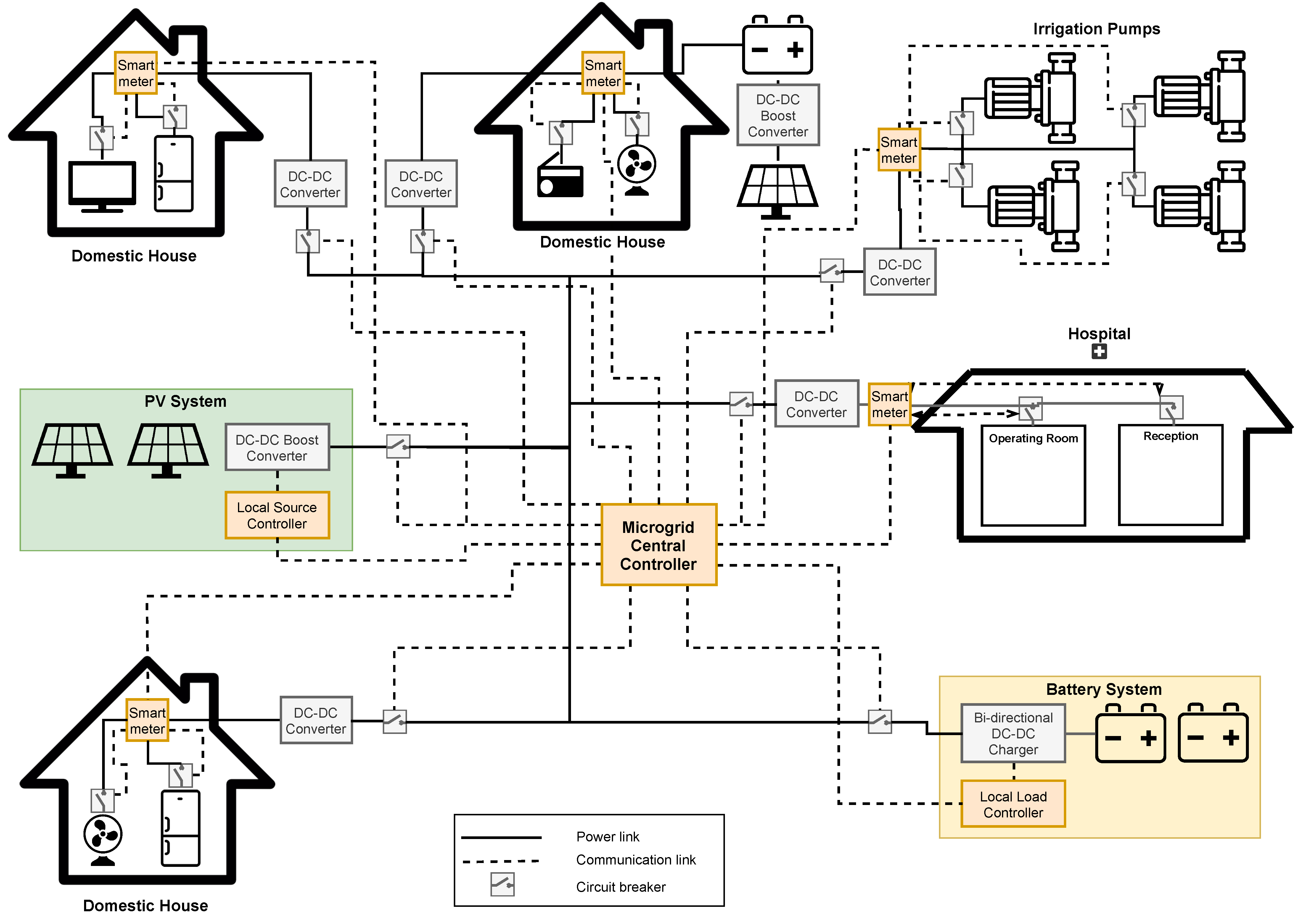
This study considers an islanded DC-based microgrid for a remotely-located off-grid rural community. The microgrid uses Photovoltaic (PV) technology to power the community that consists of around 100 households, ten local businesses, agricultural irrigation system, and a local medical centre. The use of DC technology improves power efficiency by minimising DC-AC conversions during microgrid operations. DC devices can be fed directly into the central distribution system without the need for lossy power conversions. The use of DC also simplifies power control and monitoring due to the elimination of frequency synchronisation issues.
The microgrid uses a centralised setup of PV panels as the primary source of power in the system. The power generated is fed into the main system bus and distributed to all households and local businesses in the community. The microgrid also uses a centralised power storage configuration which consists of a lead-acid battery system. This system provides additional power when power demand in the microgrid exceeds the capacity of the PV system or when the PV system cannot generate power, e.g., during night time. A few houses also have small scale PV installations and storage units for their own local needs, with the capacity to feed any excess power into the central system.
Figure 1 shows the structure of the community DC microgrid considered in this study. The microgrid follows a radial topology with households generally located within 1 km of the centralised generation system. It consists of two main subsystems: power and communication. The power subsystem consists of a network of power devices connected by electrical cables to distribute power from the source to all loads in the system. The communication subsystem consists of a network of smart devices/controllers wirelessly linked and exchange messages to control and monitor microgrid operations.
The PV system is connected to the main bus within the power network via a DC-DC boost converter. The task of the converter is to regulate the output voltage of the source and ensure maximum power is extracted and supplied to the grid by the PV system. The lead-acid battery system connects to the main bus via a DC-DC bidirectional charger. The converter’s main task is to regulate the battery charge/discharge voltage and the power supplied by the battery system during excess demand. All loads connect to the main bus via DC-DC converters, which regulate the voltage to the appropriate levels used by the loads.
The microgrid central controller (MGCC) connects via WiFi to all other local controllers and smart meters within the communication network. The MGCC uses this network to coordinate the operation of the whole microgrid by sending and receiving control/monitoring signals. In turn, the local controllers and smart meters use these signals to manage their local converters’ operations. In this study, components in the communication network consist of IoT devices such Raspberry Pis, Arduinos, and their sensors.
4.2. Control Scheme
The control scheme for the DC microgrid follows a centralised communication-based control mechanism [31]. The scheme is coordinated by the central component—microgrid central controller (MGCC)—that collects all measurements from local controllers and decides the subsequent actions by generating command signals used for voltage control and power management. The control system relies on a secure and reliable communication system for exchanging control and monitoring signals.
The control system has two layers: primary and secondary. The primary control layer ensures that the DC converters continue to operate without deviating from the predefined parameters. This task is done by local controllers, which continuously monitor local state variables and maintain the operating points of the converters. In this layer, the local controllers are directly connected to the converters, and the control operations do not rely on the communication system.
The secondary control layer maintains the microgrid voltage level by compensating for the voltage deviation caused by the primary control mechanism. This control is implemented by the microgrid central controller that receives voltage measurements from the local controllers and sends control commands in voltage reference values via the communication system. The MGCC sets the operational modes of each converter and manages their operations via the local controllers.
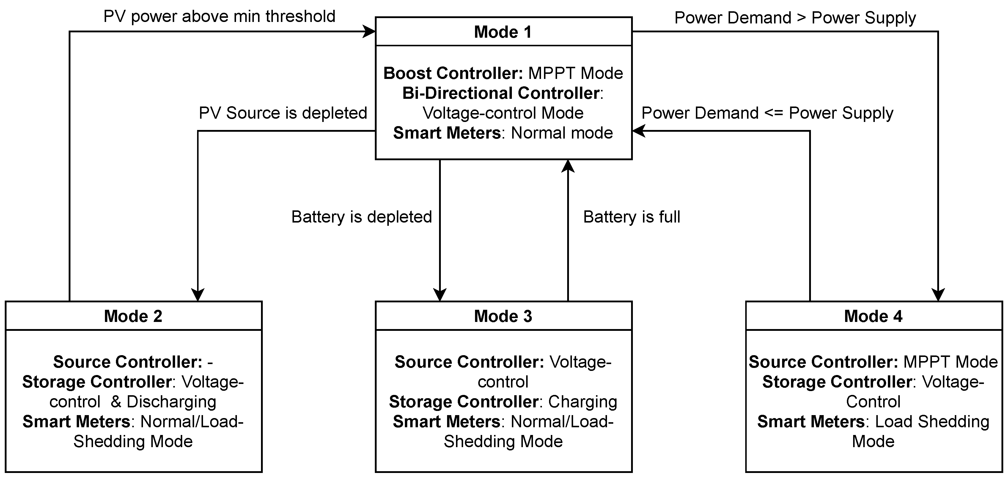
The secondary control layer is also responsible for power management in the microgrid. It ensures that there is a balance between power supply and demand. The MGCC continuously monitors power parameters (input/output voltages and current) from local controllers and smart meters in the microgrid. The MGCC uses these parameters to determine the operational power status of all resources and perform the appropriate actions to return the microgrid system to stable power operation. Figure 2 shows the centralised secondary control scheme followed by the microgrid.
The scheme operates in four different modes depending on the status of resources in the microgrid. Transitions from one mode to another occur through communication signals exchanged between controllers. Under normal conditions, the microgrid operates in Mode 1. In this mode, the bidirectional storage controller functions in a voltage-control mode where it regulates the microgrid’s DC bus voltage. The boost source controller operates in MPPT mode, where it extracts maximum power from the PV panels. All smart meters also function in normal mode, where all appliances get power. The MGCC monitors power parameters and the system’s operational status by collecting data from the local controllers and smart meters.
If power from the PV source goes beyond the minimum threshold or the source converter malfunctions, the boost controller will send a signal to the MGCC. The MGCC will trigger a discharge signal to the bidirectional storage controller, and the microgrid will transition from Mode 1 to 2. The battery system will supply all the power, and the bidirectional controller maintains the bus voltage. If power demand exceeds supply, the MGCC will also trigger load shedding commands to the smart meters. The smart meters will operate in load shedding mode with non-critical appliances shut down until sufficient power is available again.
If the state-of-charge (SoC) goes below the minimum threshold, the bidirectional charge controller will signal the MGCC. The MGCC will trigger a charge signal to the bidirectional storage controller, and the microgrid will transition from Mode 1 to 3. The boost controller will continue to operate in MPPT while the bidirectional storage controller maintains the bus voltage. In this mode, part of the PV power is used to charge the battery system, and the MGCC will trigger load shedding commands if the remaining power cannot satisfy all loads in the system.
If the MGCC detects that power consumption has exceeded the supply from both the battery and PV panels, the microgrid will transition from Mode 1 to 4. All controllers will continue to operate in their previous modes. However, the MGCC will trigger a load shedding command to the smart meters and shut down all non-critical loads until power supply and demand balance again.
5. Communication and Threat Models
5.1. Communication Model
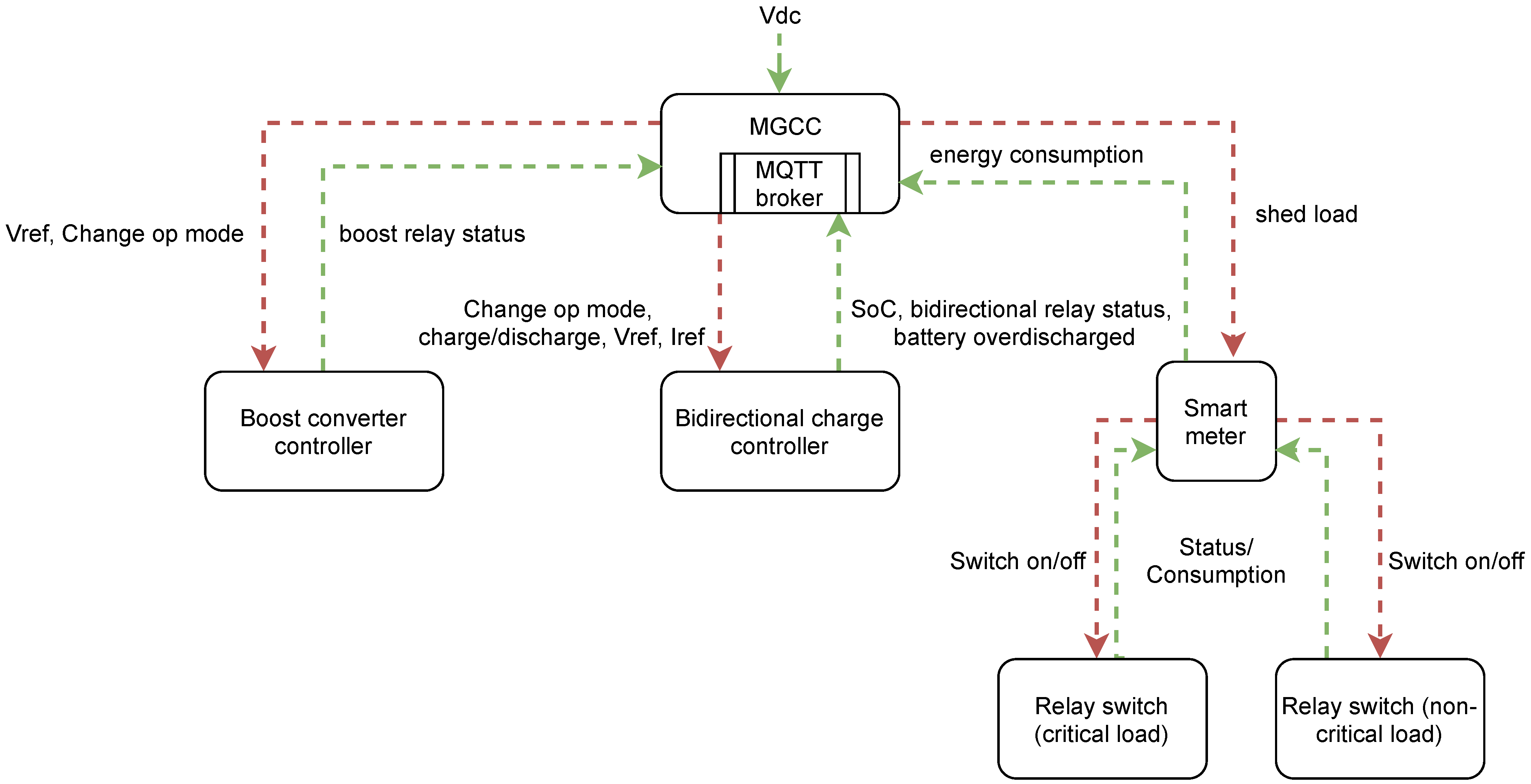
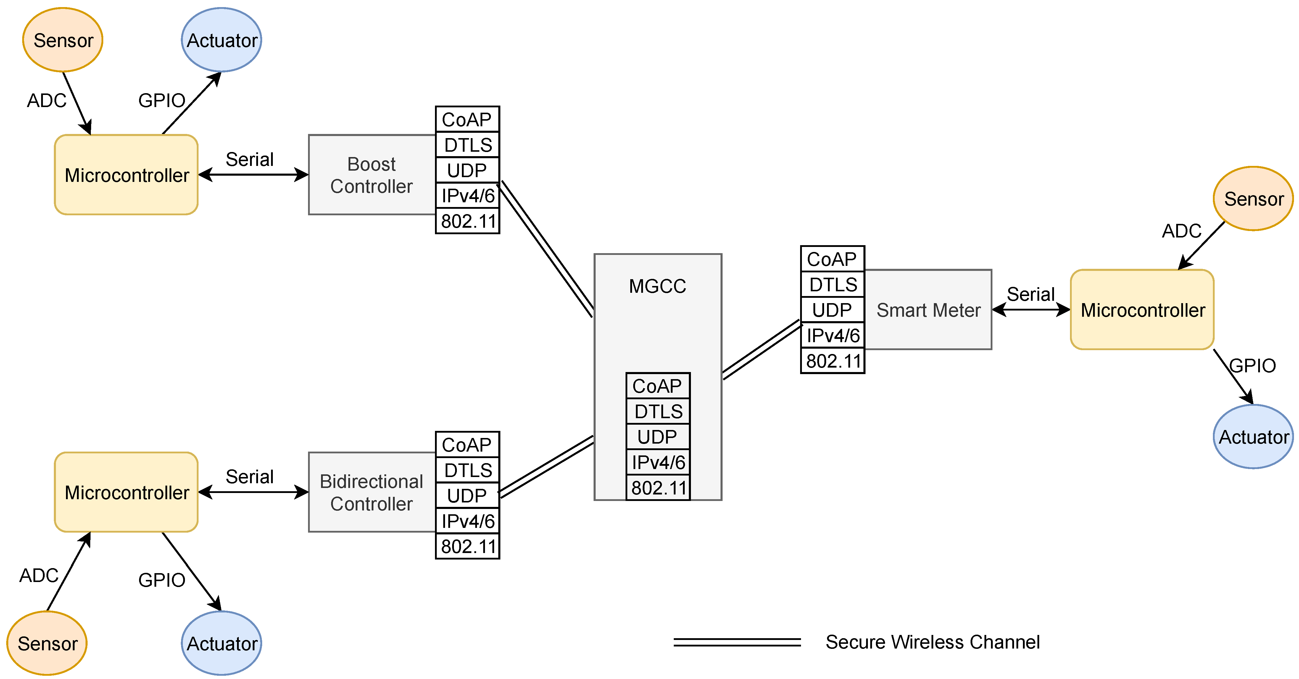
The microgrid control scheme requires a communication infrastructure for controllers and other resources to exchange information and optimise their local operation. In addition, the infrastructure needs to be fast, reliable, and secure to ensure the MGCC can accurately communicate with local controllers and smart meters [32]. To satisfy these requirements, the study assumes a centralised communication model, as shown in Figure 3.
The system allows the MGCC to control microgrid operation by sending and receiving two signals: command and status. Command signals are generated by the MGCC and carry control commands that regulate the function of other components in the microgrid. For instance, the MGCC generates and sends load shedding command signals to smart meters to reduce the power consumption of loads. All local controllers and smart meters also periodically generate status signals. They carry information and other historical data used by the MGCC to assess the operational status of the microgrid and determine the subsequent actions as defined by the control algorithm. Table 2 summarises the different signals transmitted within the communication system for power control purposes.
The systems use protocols based on the standard IP-based IoT protocol stack for end-to-end communication. The total end-to-end latency of the communication system depends on several factors [33]:
- Transmission latency: time to transmit all data packets over the communication channel. This value depends on the bandwidth of the medium and the amount of data to be sent.
- Processing latency: time for transforming the data into packets and vice versa through the communication stack. It includes operations packet encoding/decoding, switching, medium adaptation, routing, etc.
- Propagation latency: time for the data packet to travel over the communication channel from sender to receiver. This value depends on the properties of the transmission medium and the distance between the sender and receiver.
- Queuing latency: time data packets need to wait before being transmitted by the sender.
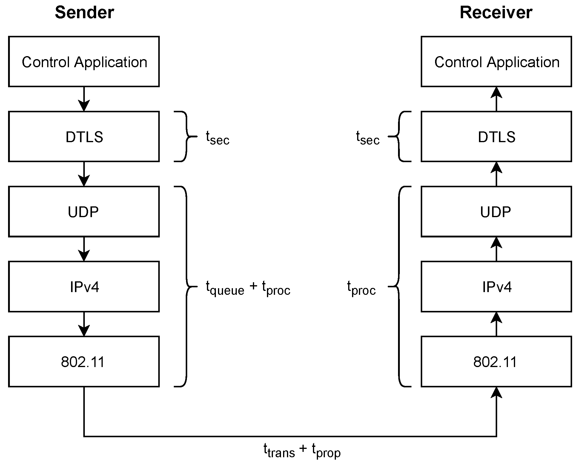
Figure 4 shows the components of the protocol stack contributing to the end-to-end latency in the microgrid communication model. For secure communication, in addition to the processing latency, there is also a security latency for establishing a secure communication channel. This additional latency involves security operations such as encryption/decryption, security handshakes, integrity verification, etc. Thus, the total communication latency can be expressed as follows:
where is the total latency, is the transmission latency, is the processing latency, is the security latency, is the propagation latency, and is the queuing latency.
For the case of the microgrid communication system, the main focus will be on optimising the security and queuing latency. The amount and type of security processing performed on the messages significantly impact how long control commands reach the intended recipients securely. Queuing delays occur in situations with network congestion due to the large amount of traffic generated by all components in the system. The other delay factors have minimal impact in this case. The propagation delay is fixed, and all controllers are within the maximum WiFi range. The transmission delay plays a minor role since bandwidth requirements of power control operations do not exceed the maximum supported by the communication channel.
5.2. Threat Model
This study considers a wireless-based microgrid communication system with cyber-physical components—MGCC, boost converter controller, bidirectional charge controller, and smart meters—that are physically accessible and insecure. These components are involved in both the physical power subsystem and the communication subsystem. Due to this situation, the components are susceptible to cyber attacks that can disrupt control operations in the physical power subsystem.
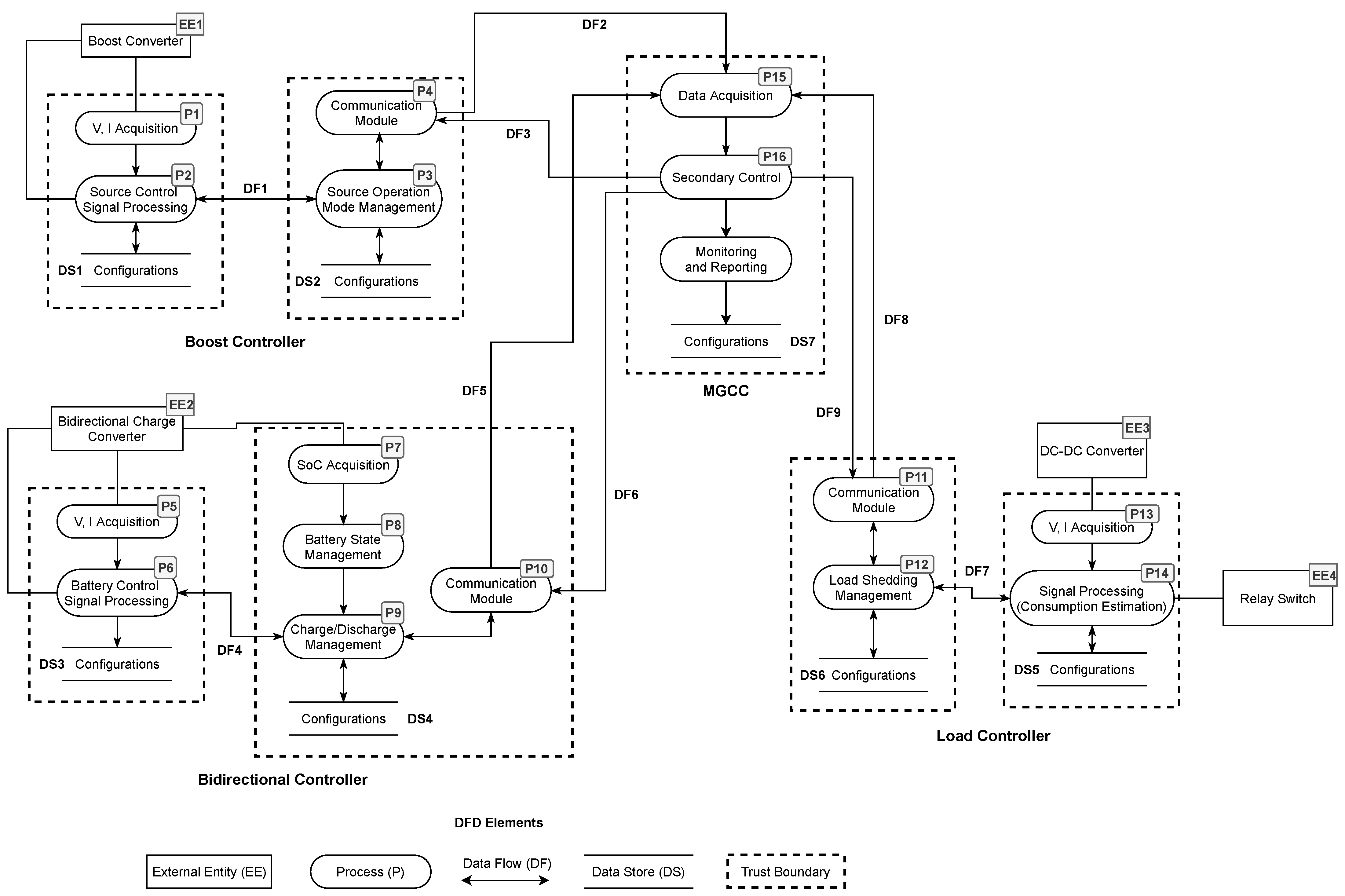
For the threat model, we assume an attacker who has physical access to the network and can capture messages and passively collect information; intercept and modify messages; interfere and disrupt the exchange of messages. Figure 5 shows the data flow graph (DFG) of the microgrid communication system. The DFG helps analyse the threats by highlighting all external endpoints, the flow and storage of data, and functional units, i.e., processes that transform the data in the system. The DFG also helps to indicate the trust boundaries and domains that segregate the system into trusted and untrusted components.
Based on the DFD, we identify several points in the system that are vulnerable to cyber threats and attacks. Table 3 categorises and describes these threats. Due to the strong dependency between the cyber and physical parts of the system, cyber threats also negatively impact power operations, as described in the table.
6. Microgrid Communication Requirements
6.1. Performance Requirements
To ensure a safe and reliable power system, power control operations in a microgrid have strict real-time requirements. Therefore, the communication system needs to deliver control commands and replies to their recipients with minimal delay.
In general, due to different needs, microgrids use different application-layer communication technologies in the supply vs. demand side of the power generation process [37]. On the supply side, popular protocols include Modbus, Distributed Network Protocol 3 (DNP3), and IEC 61850. These protocols are used for device communication in the transmission and substation automation systems and have their own unique performance requirements.
On the demand side, IoT-based communication protocols are increasingly being used. These protocols have strict performance requirements in terms of message delay/latency that they need to fulfil [38]. Table 4 shows the delay requirements for communication messages in a microgrid according to the European Telecommunications Standards Institute (ETSI) standards [39]. The latency requirements for control information are shown to be between 16 ms and 100 ms. Failure to meet these limits can cause dangerous voltage deviations and other harmful effects in the microgrid [32].
Each component in the communication path contributes a certain amount of delay to the process. As described in Section 5.1, the total communication latency consists of packet processing times at the sender and recipient and the transmission time through the physical medium. For secure communication implementations, operations to establish a secure channel consume a big part of the total communication latency. Previous research has shown that secure implementations of IoT communication protocols have significant latency—mainly due to the extra security handshakes—that is not suitable for power control purposes [13]. Each extra packet exchange during the handshake process increases the connection latency by adding more message round-trip times (RTT).
Therefore, the main performance goal of the proposed communication system is to ensure the total () latency of the secure exchange of control messages stays below the recommended value of 100 ms by optimising the security handshake process, which is the main contributing factor.
In addition, the system also has scalability requirements. As the size of the microgrid and its components increases, network activity in the communication system also increases which can lead to congestion. This congestion can overwhelm the MGCC with packet processing causing delays in delivering critical control command messages due to packet buffering and interference. The proposed system needs to provide a stable and predictable processing environment for control messages in the microgrid to prevent this performance problem. The system should ensure that the total latency of critical control messages remains below the recommended value as the number of controllers and smart meters increases in the microgrid.
6.2. Security Requirements
There are many security threats against the communication system—as described in Section 5.2—that can affect the power control operation of the microgrid. The main security objective of the proposed system is to protect the microgrid from these threats and provide a more reliable and secure environment for components, i.e., controllers and smart meters, to communicate and exchange control messages. To achieve this objective, the system needs to fulfil the following security requirements:
- Confidentiality: The proposed system needs to protect private/proprietary information exchanged between controllers and smart meters from unauthorised disclosure to third parties. Previous research showed that disclosing this information can facilitate other serious attacks [35].
- Integrity: Controllers involved in the communication process should be able to detect unauthorised modification of control messages to prevent incorrect power control decisions.
- Replay detection: Controllers should have the ability to detect valid messages that have been replayed to prevent attackers from using previously captured communication to execute unauthorised control commands.
- Authentication: The proposed system should have mechanisms to allow controllers and smart meters to prove their identities and verify whether received messages and commands were sent by the intended component and not by an impersonator.
- Availability: The system should ensure that all components are available at all times and can communicate promptly. Controllers and smart meters should detect and recover from DoS attacks that can disrupt their operation by preventing the collection of accurate state information and the generation of correct control decisions.
7. The Proposed Low Latency Communication Architecture
This section presents our proposed low-latency secure communication architecture for power control in the constrained environment of an IoT-powered DC microgrid. The architecture provides end-to-end communication security between components with minimal impact to the latency of control commands. It also guarantees and maintains this latency performance as the microgrid scales, regardless of the system’s increased network activity and congestion. The architecture achieves these objectives using existing application-level IoT protocols with two main improvements: secure protocol with optimised security handshake that minimises latency and a a fixed-priority preemptive traffic scheduler mechanism that maintains latency performance of critical control commands.
7.1. Architecture
The proposed communication system architecture relies on an IoT stack with the secure implementation of the CoAP protocol. CoAP is a popular lightweight protocol used in IoT environments [18]. It is similar to the HTTP protocol but implemented on top of UDP for efficiency. The system uses the protocol to exchange power control messages within the communication system. The MGCC, local controllers, and smart meters all act as CoAP clients and servers and exchange CoAP messages. When specific power events occur, the MGCC sends CoAP request messages containing charge/discharge commands, load shedding commands, and change operation mode to the local controllers and smart meters. On the other hand, local controllers and smart meters send CoAP request messages consisting of power state parameters, i.e., voltage, current, state-of-charge (SoC) to the MGCC.
The architecture uses CoAP/DTLS to provide end-to-end security between communicating nodes. DTLS is an optimised version of the TLS protocol built on top of UDP suitable for IoT applications. The protocol provides similar services as TLS, including encryption, message integrity, and authentication. We use the latest version of the protocol—DTLS 1.2—configured in pre-shared key mode with AES-CCM. This mode is more efficient compared to the public key mode, which requires significant computational resources. The architecture uses the AES algorithm with an 8-byte CBC-MAC in counter mode to provide message authentication. For message integrity, it uses the HMAC-SHA256 hashing algorithm. This latest version of DTLS also protects against Distributed Denial of Service (DDoS) attacks by generating DTLS cookies. Figure 6 shows the proposed secure microgrid communication using CoAP/DTLS 1.2.
The secure communication architecture provides the following security services: device authentication, which prevents an attacker from spoofing another component and sending unauthorised control commands, e.g., a shut-down command to the local source controller; message encryption which protects disclosure of sensitive information to potential attackers, e.g., monitoring power consumption for behavioural analysis; and message integrity which prevents unauthorised interception and modification of control messages which can lead to various problems, e.g., theft of power, voltage instability, and equipment damage.
7.2. Optimised Security Handshake
To minimise the communication latency of control commands and measurements in the proposed system, we need to shorten the time to establish a secure connection between controllers and smart meters. We achieve this objective in the architecture by developing an optimised DTLS security handshake process based on the TLS False Start option [40]. This optimised process minimises communication latency by reducing the round-trip time (RTT) during the initial security handshake.
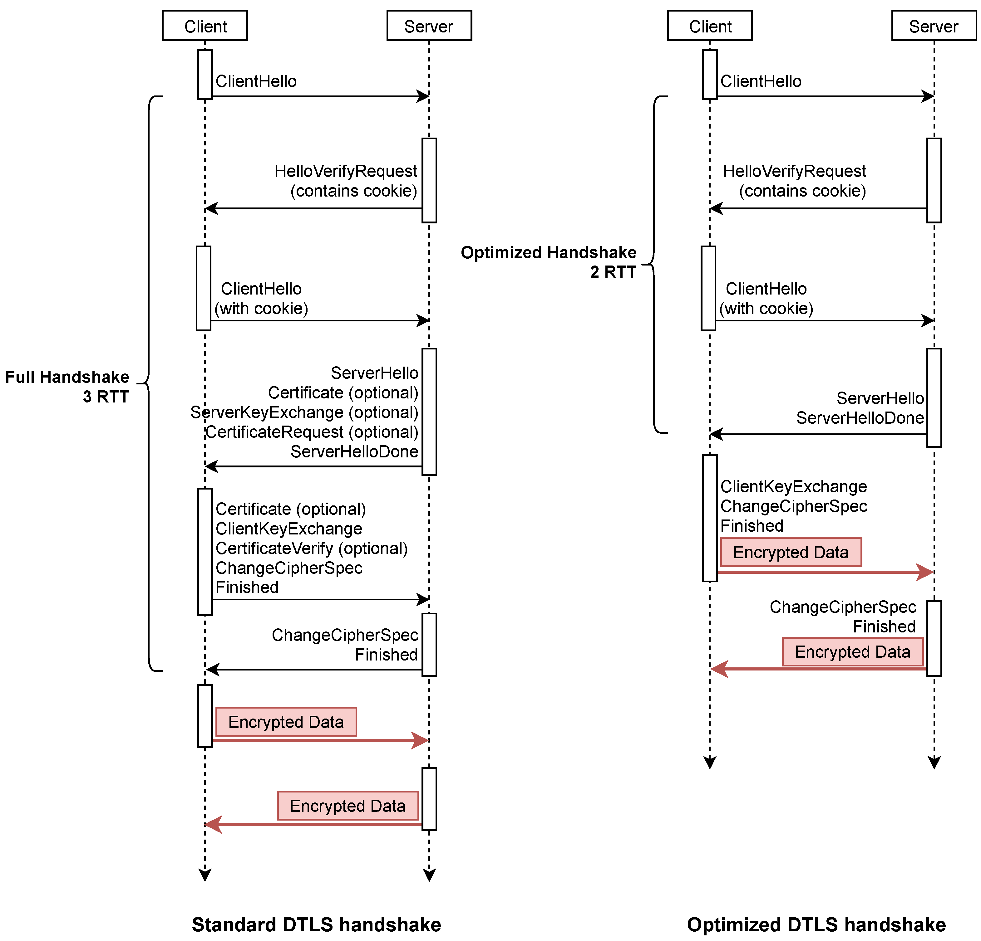
The standard DTLS 1.2 implementation includes a security handshake that requires 3 RTTs to establish a secure encrypted connection. The first RTT consists of a cookie exchange mechanism used to prevent DDoS attacks. The second RTT includes ClientHello and ServerHello exchanges and is used by the client and server to agree on the connection’s security parameters and session keys. The final RTT involves verifying the integrity of the handshake and finalising establishing the encrypted channel.
Our implementation, however, includes an optimised security handshake that requires only two RTT to establish a secure encrypted connection. It reduces the number of needed RTTs using the TLS False Start option, which allows the client to immediately start sending encrypted application data packets after the second RTT. Figure 7 shows our optimised security handshake compared to the standard DTLS 1.2 implementation.
The optimised security handshake minimises the impact of integrating secure communication in the microgrid and allows controllers and smart meters to securely exchange control commands and measurements without affecting performance and efficiency.
7.3. Fixed-Priority Preemptive Traffic Scheduler
To ensure that the proposed low-latency microgrid communication system scales and maintains its delay performance, the architecture implements a fixed-priority preemptive traffic scheduler mechanism in the MGCC. The mechanism ensures that critical control commands are processed immediately without delay, even if there are other less essential messages in the waiting queue. The critical control commands and their processing is not affected by the increasing number of different messages as the system scales.
The mechanism divides the communication messages into two groups with different levels of priority. One group includes critical control commands and messages such as those related to controlling voltage levels and changing the operational status of local controllers. These messages are classified as high priority with strict latency requirements to ensure stable power operation. The other group includes status and power measurement messages related to local controller status and power consumption from smart meters. These messages are classified as low priority and can be delayed for a short time without causing severe consequences. However, there is a large volume of these messages as they are sent periodically in the system. However, they have a more flexible deadline and can be delayed for some time without severe consequences. Table 5 shows the classification of messages into the two priority levels.
The traffic scheduler is implemented at the MGCC in the application layer of the communication stack. The scheduler uses the fixed-priority preemptive scheduling mechanism—a well-known scheduling mechanism for real-time systems—to control the flow of control packets in the communication system. The use of such a mechanism has been shown to provide a more predictable and stable timing behaviour compared to other scheduling mechanisms [41].
The scheduler differentiates critical control commands and status messages into the two priority levels and processes them in queues accordingly. Each priority level has its own separate FIFO (First In First Out) queue. High priority messages are assigned to the high priority queue, while the low priority messages are assigned to the low priority queue. Messages in the high priority queue are always processed first in a FIFO manner. The low priority queue is processed only when the high priority queue is empty. Algorithm 1 shows the procedure followed by the scheduler.
| Algorithm 1: Traffic Scheduler Algorithm |
 |
The algorithm has two main stages: priority classification and message sending. When status and measurement messages from local controllers and smart meters are received in the classification stage, they are first classified as low priority. Then, they are processed, and their responses are placed in the low priority queue, ready for sending. On the other hand, when critical control events occur, control commands are generated, classified as a high priority, and then placed in the high priority queue ready for sending. The scheduler always selects messages from the high priority queue for sending before the low priority queue in the sending stage. This process allows the system to scale and guarantees low latency performance for high priority control commands at all times.
8. Evaluation
8.1. Hardware Prototype
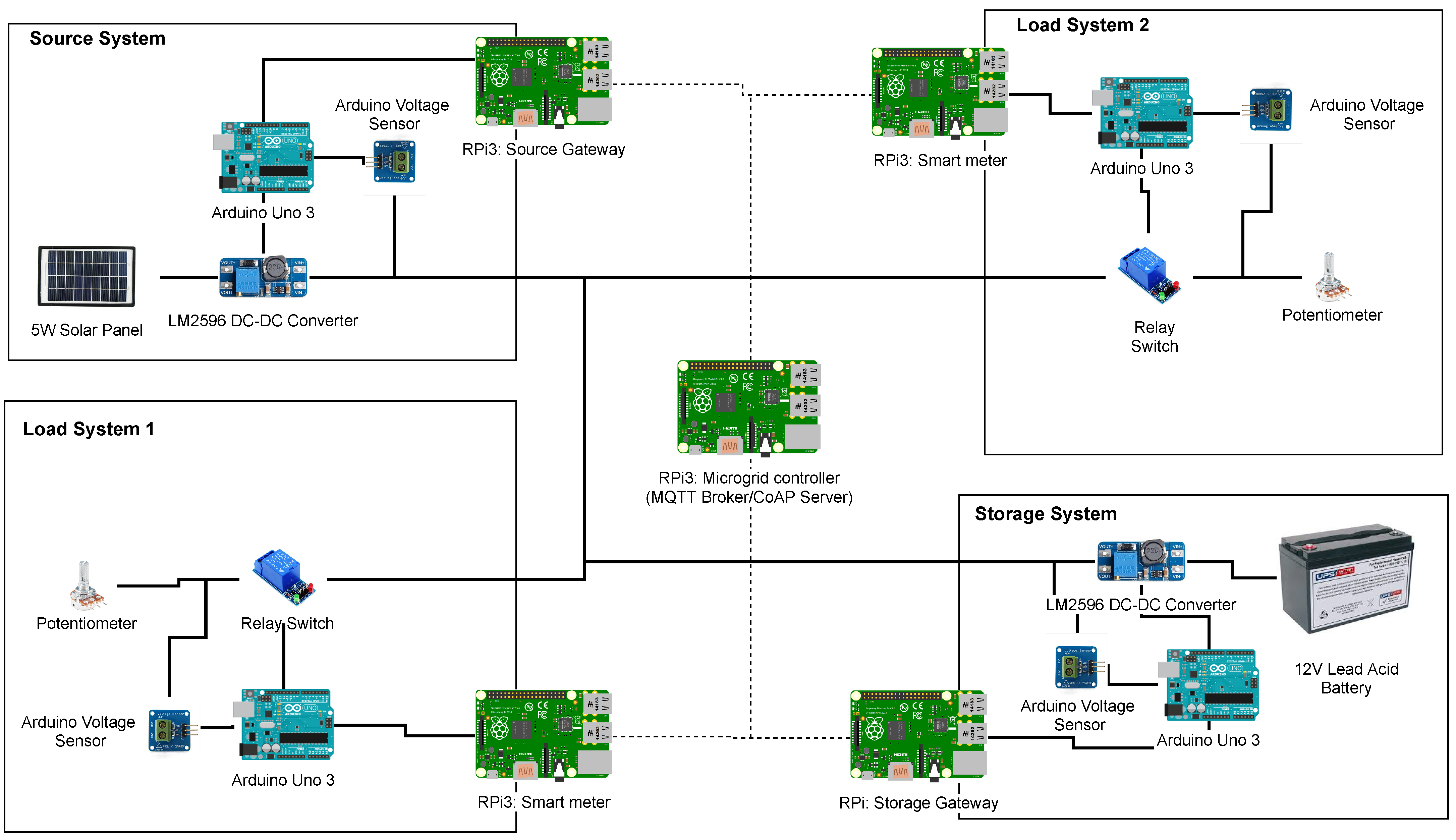
To evaluate the secure communication design, we built a lab-scale hardware prototype of an IoT based DC microgrid as shown in Figure 8. The prototype follows the structure of the DC microgrid considered in this study.
The prototype consists of three subsystems—source, storage, and load—connected by an electrical cable (main system bus) to form a microgrid system. Table 6 lists all components used to construct the prototype.
The source subsystem is powered by a 13.5 V 5 W solar panel connected to the main bus via an LM2596 DC-DC converter that regulates output voltage between 1.23 V and 30 V. The converter is connected to an Arduino Uno Rev3 microcontroller which acts as the local source controller. The controller sends control commands to the converter and manages its operation. It also monitors the output voltage of the converter using an Arduino compatible voltage sensor.
The storage subsystem consists of a 12 V rechargeable lead-acid battery also connected to the main bus via an LM2596 DC-DC converter that regulates the battery charge and discharge voltage levels. The converter is connected to an Arduino Uno Rev3 microcontroller that sends control commands and acts as the local charge controller. The microcontroller is also connected to a voltage sensor that monitors the input/output voltage of the battery system.
There are two instances of the load subsystem that each consists of 1 kOhm potentiometers used to simulate different load devices. These potentiometers are connected to the main system bus via 1-Channel 5 V Relay modules that are controlled by Arduino Uno Rev3 microcontrollers. The microcontrollers also use voltage sensors to monitor the DC voltage supplied to each load.
Each subsystem consists of a Raspberry Pi 3 Model B+ (RPis) connected to the local controller via a USB cable. These RPis act as communication gateways for the local controllers and exchange messages via the 802.11 (WiFi) wireless protocol. The protocol offered maximum compatibility and simplified the implementation of the prototype. Furthermore, to ensure a stable communication channel, each RPi was positioned within the communication range for WiFi. Table 7 shows the WiFi parameters as configured in each gateway.
Each gateway implemented the secure CoAP+DTLS communication stack using TinyDTLS, an open-source library ported from Contiki OS. Each CoAP+DTLS client and server was configured with the following cypher suite: TLS_PSK_WITH_AES_128_CCM_8. The pre-shared key with AES-CCM mode was used for encryption, while the HMAC-SHA256 hash algorithm was used for the Message Authentication Code (MAC). The length of the MAC was set at 8 bytes.
The microgrid central controller (MGCC) was implemented in one of the Raspberry Pi 3 devices running FreeRTOS, a popular real-time operating system (RTOS) for embedded devices. The operating system port provides real-time features such as a preemptive scheduler, timers, semaphores, etc. These features were used to implement the central control algorithm. Two sets of tasks with different priority levels were created using the xTaskCreate() API. One set of tasks for critical control operations was set at a higher priority (level 5), while the other set for less critical status messages was set at a lower priority (level 1).
8.2. Performance
This section presents the observed performance results of the proposed secure low-latency architecture as implemented on the lab-scale hardware microgrid prototype. It compares the architecture’s performance in terms of latency and scalability against other implementations using standard IoT security protocols. It shows how our implementation performs in terms of total communication latency and maintains it as the number of components in the microgrid increases.
The performance results were obtained by simulating a control scenario where the MGCC sends a discharge signal to the bidirectional controller to obtain additional power from the battery system. The scenario was repeated 10 times with the communication traffic captured and analysed using Wireshark. The timing information for each packet was extracted and processed, and the average values were tabulated according to the specified performance metrics.
8.2.1. Latency
As described in Section 6.1, to effectively support power control operations in a microgrid, the total latency of communication exchange between components needs to be between 16 ms and 100 ms. We evaluated the total latency of our proposed optimised, secure, low-latency architecture and compared it to the standard secure CoAP implementation. We measured the total communication latency to set up a secure connection and send a battery discharge command between the MGCC and the bidirectional controller. We also compared latency to that obtained from other standard secure communication protocols used for IoT-enabled power systems as described in Section 3, i.e., MQTT/TLS and XMPP/TLS.
We conducted 10 iterations of the scenario for each implementation and recorded the total end-to-end latency for the delivery of the control command from the MGCC to the bidirectional controller. Table 8 and Figure 9 provide summary statistics of the latency measurements for each implementation. Each measurement represents the total latency from the detection of the control event to the delivery of the control command at the destination.
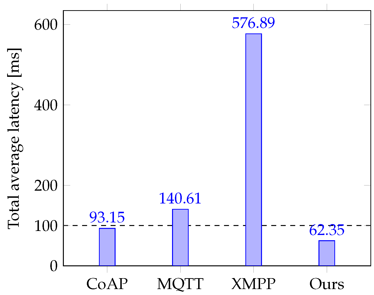
Figure 10 compares the total average communication latency of control commands observed for each different implementation.
Results show that only our proposed low-latency architecture and the standard CoAP/DTLS implementation had a total latency below the 100 ms maximum threshold suitable for exchanging power control information. The standard CoAP/DTLS implementation was slightly below the maximum threshold with a total latency of 93.15 ms. While the average total latency for the standard CoAP/DTLS implementation was below the recommended threshold, it was only by a minimal margin. There were few cases where the measured latency exceeded the threshold. On the other hand, our proposed low-latency implementation performed the best with the lowest average latency of 62.35 ms, well below the threshold. Using the optimised security handshake, we reduced the total latency by 33% compared to the standard CoAP/DTLS implementation.
8.2.2. Scalability
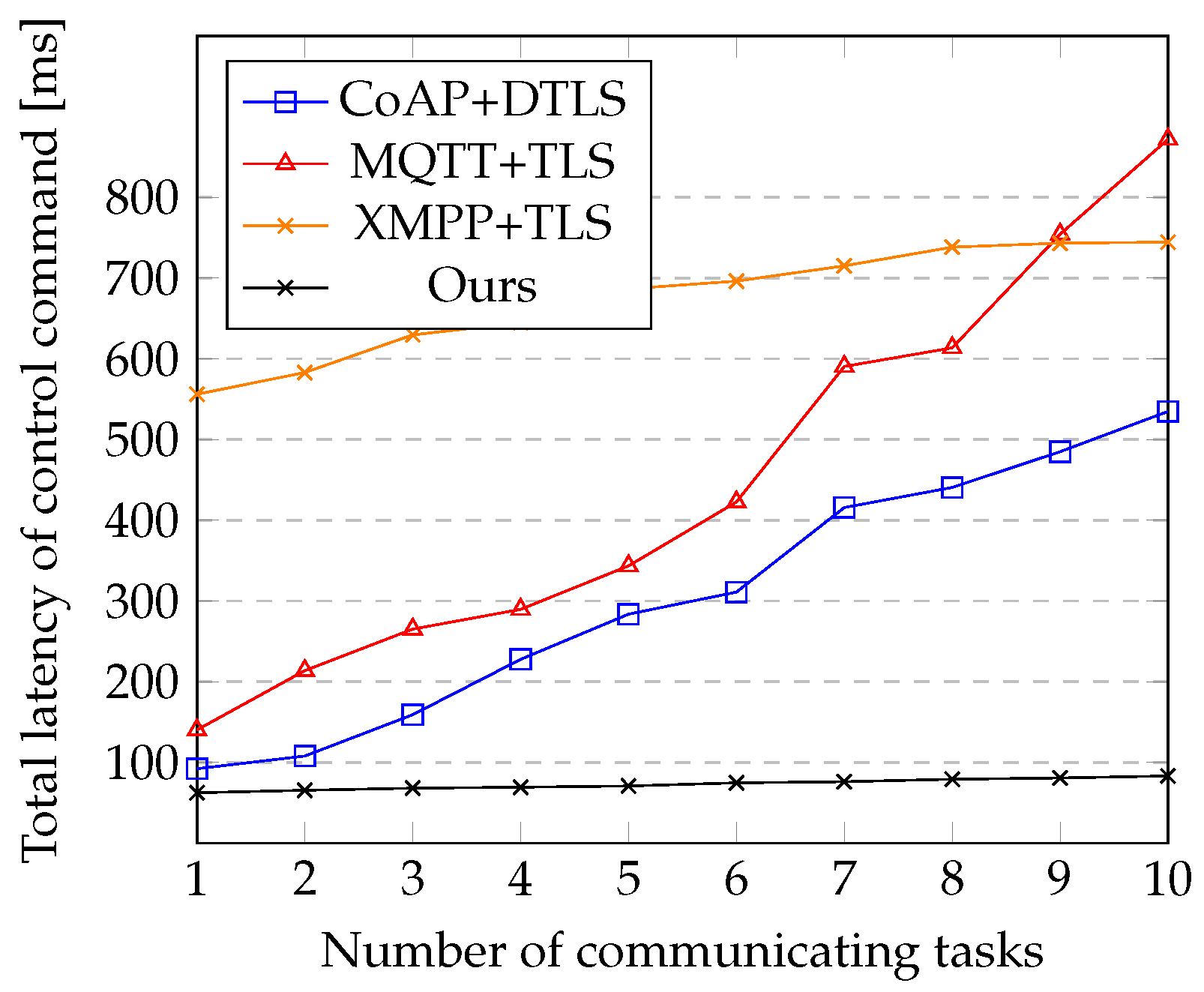
Another vital performance requirement, as described in Section 6.1, is the ability of the secure communication system to scale and maintain latency performance as the microgrid increases in size. We evaluated the scalability of our proposed implementation by analysing the relationship between the number of communicating components in the microgrid and the resulting total latency of the battery discharge control command from the MGCC to the bidirectional storage controller. We simulated the increase in communicating components by adding the number of threads in each controller sending voltage and current status messages. We measured the total end-to-end latency for the delivery of the control command to see how it was impacted by the increased traffic. We also tested other implementations using standard secure IoT protocols and compared their scalability to our proposed architecture. Figure 11 shows how the total latency for the delivery of control commands is affected by the increase in communicating tasks in the system.
As expected, for each implementation, the total average latency of the control command increased as the number of communicating tasks grew in the microgrid. The additional traffic introduced processing delays at the MGCC, affecting its ability to send the battery discharge control command promptly. Compared to other implementations, our architecture had the lowest change in latency as the number of communicating tasks changed. It had an initial latency of 62.347 ms, and it only slightly increased to 83.153 ms (33.37% increase) as the number of communicating tasks in each controller increased from 1 to 10. The standard implementations of CoAP+DTLS and MQTT+TLS also had low latencies initially. However, these values increased significantly as the number of tasks in the system inflated. The CoAP+DTLS implementation had a 480.4% increase in latency, while the MQTT+TLS had a 522% increase in latency. The XMPP+TLS implementation also had a low rate of growth in latency (33.88%). However, its initial latency was still significantly larger (556.005 ms) compared to the others.
Similarly, we also assessed and scalability of our proposed implementation by measuring the throughput of control messages to see how it is impacted as traffic increased in the communication system. Figure 12 shows how the message throughput at the MGCC for each implementation changes as the number of communicating tasks increase in the system. Results showed that our implementation was able to scale and maintain an increased rate of throughput compared to the other standard implementation. As the number of tasks increased, the total number of control messages going through the MGCC also increased. The MQTT/TLS and XMPP/TLS, being TCP based, had an initial larger number of messages and throughput—21 packets/sec and 19 packets/sec—that steadily increased to a maximum of 168 packets/sec and 133 packets/sec respectively. However, both implementations failed to scale after eight tasks with their throughput performance decreasing.
On the other hand, both our implementation and the standard CoAP/DTLS started were able to maintain an increased throughput performance compared to the others. Both implementations peaked at 130 packets/sec. However, our implementation was able to scale and increase the throughput throughout the test while the standard CoAP/DTLS implementation scaled up to eight tasks and started to decrease afterwards.
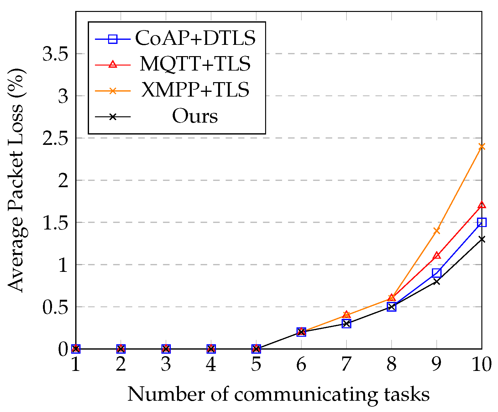
Our proposed architecture implements a fixed-priority preemptive traffic scheduler at the MGCC. This scheduler ensures that control commands are given the highest priority and are processed immediately regardless of network conditions. This allows the architecture to maintain latency performance within the recommended threshold (max 83.153 ms) and a consistent throughput (max 130 packets/sec) as the size of the microgrid scales up. Other standard implementations without the scheduler, however, do not have the same performance characteristics. As the number of components in the microgrid increases, communication traffic to the MGCC also increases, causing congestion and processing delays. These delays increase the latency of control commands beyond the recommended threshold. Figure 13 shows and compares the average packet loss of each implementation as the number of communicating nodes increased in the system.
As expected, the average packet loss experienced by each implementation gradually increased as traffic increased in the communication system. As the number of nodes exceeded five, controllers in each implementation started to experience packet drops due to the traffic congestion within the network. Each implementation experienced a similar level of percentage packet loss with the maximum—XMPP/TLS reaching 2.4% packet loss at 10 tasks. The TCP-based implementations—MQTT/TLS and XMPP/TLS—experienced more loss due to the higher number of packets involved in the communication. This increased loss caused packet re-transmissions in the case of MQTT/TLS and XMPP/TLS which found them to be the least scalable. On the other hand, using the optimised handshake and priority-based scheduling, our implementation is still able to scale and maintain consistent latency for the critical control commands. It outperforms the standard CoAP/DTLS implementation which lacks these features.
8.3. Security
This section analyses the security of the proposed low latency communication architecture. It describes the main security threats and how the architecture mitigates them.
8.3.1. Unauthorised Access and Interception
The proposed architecture implements several measures to prevent unauthorised access and interception of the sensitive communication system. First, it provides end-to-end security for the communication channel using the CoAP/DTLS implementation. Only the sender and receiver possess the cryptography keys for accessing the secure channel. All messages are encrypted and signed before being sent over the communication channel. Second, each sender uses cryptographic hash algorithms to generate message access control (MAC) codes attached to every message. These MAC codes prevent any entity from reading and modifying messages without detection by the sender or receiver. Third, the system also uses the authentication mechanisms available in CoAP/DTLS to protect against spoofing attacks. Each sender and receiver device possesses a private key and a public key certificate used for authentication.
8.3.2. Sensitive Information Disclosure
The proposed architecture prevents the disclosure of sensitive information by ensuring control signals are encrypted at every point in the communication system. At rest, each device uses AES encryption to store sensitive control information in its database. Only authorised entities with valid keys can access this information. During transit, all messages are encrypted using DTLS 1.2, preventing third parties from gaining access to the communication. During session establishment, the sender and receiver agree on a secret session key that is used to secure all subsequent communication. This keeps the communication private even if an attacker intercepts it.
8.3.3. DDoS Attack
The architecture uses the option cookie feature available in DTLS 1.2 to prevent DDoS attacks on critical components in the communication system. This feature introduces a stateless cookie during the initial communication handshake. The server uses the cookie to validate clients and only accept legitimate connection requests. When a server receives a ClientHello message, it first sends back a HelloRetryRequest response containing the cookie. The client responds by re-sending its ClientHello message with the provided cookie. The server validates the cookie and uses it to decide if it should accept the connection and allocate appropriate resources. This mechanism forces clients to prove their reachability and prevents DDoS attacks using spoofed IP addresses.
8.3.4. Replay Attack
The proposed architecture prevents replicating captured control messages by using unique timestamps for each message in the communication system. This helps senders and receivers distinguish new messages from other old replayed messages. A receiver would reject any attempts by an attacker to use old messages due to the expired timestamp.
8.3.5. Repudiation Attack
The secure architecture prevents device repudiation attacks using digital signatures and private key authentication mechanisms in the DTLS 1.2 standard. Every device in the system possesses a unique private key to sign all messages being sent through the communication channel. As a result, every command and status message can be attributed to a specific sender device, and no client can impersonate another without being detected.
9. Conclusions
Microgrids require reliable, efficient, and secure communication systems to improve the power distribution process’s efficiency and reliability. These communication systems need to provide these features while also adhering to the strict performance requirements of power control operations in microgrids. However, building such a system is challenging since standard secure communication implementations introduce extra performance penalties unsuitable for power operations.
This study shows how to design and implement a secure communication architecture for power control in a microgrid without impacting performance. It proposes a low-latency secure communication architecture for an IoT-based off-grid DC microgrid. The architecture is built on existing standard secure IoT protocols—CoAP/DTLS—and provides end-to-end communication security to exchange power control commands while satisfying the low-latency requirements of power control operations. The architecture also supports scalability requirements and helps the communication system maintain the low-latency performance even as the microgrid grows in size.
The proposed communication system achieves these goals using a novel architecture based on two main approaches. First, the architecture develops a low latency version of the standard CoAP/DTLS implementation with an optimised security handshake. The handshake is optimised by reducing the number of round-trip exchanges during connection setup, thereby reducing the overall latency of the whole communication process. Second, the architecture introduces a fixed-priority preemptive traffic scheduler component that ensures that critical control messages are delivered with low latency in all conditions. The architecture segregates messages into two priority levels and ensures that critical control messages are always processed ahead of other existing less critical messages.
Results show that the proposed architecture can provide the required secure communication environment while maintaining the low latency performance needed for control operations. Compared to other standard secure implementations for IoT environments, the architecture provides the lowest communication latency below the recommended values. The architecture can maintain this low latency even as the number of components in the microgrid increase. Other implementations fail to maintain this performance and exceed the recommended values as the microgrid grows. The architecture also protects the microgrid from different threats, including unauthorised modification of communication messages, disclosure of sensitive information, DDoS attacks, and impersonation attacks. This protection is beneficial for critical power control operations and facilitates more intelligent microgrid systems that can operate autonomously and use resources more efficiently.
The main limitation of the proposed architecture is that it can only support power control and monitoring functions in the microgrid. The solution fails to provide a secure communication system for power protection functions, even with optimised secure IoT-based communication protocols and a priority-driven traffic scheduling mechanism. This is due to the stringent latency requirements for power protection information, i.e., 4 ms. The power protection functions have to be provided by a different protection system consisting of current interrupting devices, protective relays, measurement equipment, and grounding.
Author Contributions
Conceptualisation, A.K. and I.B.D.; methodology, A.K.; software, A.K.; validation, A.K. and I.B.D.; analysis, A.K.; writing—original draft preparation, A.K.; writing—review and editing, I.B.D., H.T. and N.M.; visualisation, A.K.; supervision, H.T. and N.M.; project administration, H.T. and N.M.; funding acquisition, H.T. and N.M. All authors have read and agreed to the published version of the manuscript.
Funding
This research received no external funding.
Institutional Review Board Statement
Not applicable.
Informed Consent Statement
Not applicable.
Data Availability Statement
Not applicable.
Acknowledgments
The authors would like to thank iGrid a joint SIDA funded project between the Royal Institute of Technology (KTH) and the University of Dar es Salaam which provided the platform to conduct the study and supported it in terms of tools. The project aims to design and implement autonomous smart microgrids for off-grid rural communities in Tanzania.
Conflicts of Interest
The authors declare no conflict of interest.
References
- Berizzi, A.; Delfanti, M.; Falabretti, D.; Mandelli, S.; Merlo, M. Electrification Processes in Developing Countries: Grid Expansion, Microgrids, and Regulatory Framework. Proc. IEEE 2019, 107, 1981–1994. [Google Scholar] [CrossRef]
- Parhizi, S.; Lotfi, H.; Khodaei, A.; Bahramirad, S. State of the Art in Research on Microgrids: A Review. IEEE Access 2015, 3, 890–925. [Google Scholar] [CrossRef]
- Hirsch, A.; Parag, Y.; Guerrero, J. Microgrids: A review of technologies, key drivers, and outstanding issues. Renew. Sustain. Energy Rev. 2018, 90, 402–411. [Google Scholar] [CrossRef]
- Dhaou, I.B.; Kondoro, A.; Kelati, A.; Rwegasira, D.S.; Naiman, S.; Mvungi, N.H.; Tenhunen, H. Communication and security technologies for smart grid. Int. J. Embed. Real-Time Commun. Syst. 2017, 8, 40–65. [Google Scholar] [CrossRef]
- Kondoro, A.; Dhaou, I.B.; Tenhunen, H. Enhancing the Security of IoT-enabled DC Microgrid using Secure-MQTT. In Proceedings of the 2020 6th IEEE International Energy Conference (ENERGYCon), Gammarth, Tunisia, 28 September–1 October 2020; pp. 29–33. [Google Scholar] [CrossRef]
- Kumar, D.; Zare, F.; Ghosh, A. DC Microgrid Technology: System Architectures, AC Grid Interfaces, Grounding Schemes, Power Quality, Communication Networks, Applications, and Standardizations Aspects. IEEE Access 2017, 5, 12230–12256. [Google Scholar] [CrossRef]
- Marzal, S.; Salas, R.; González-Medina, R.; Garcerá, G.; Figueres, E. Current challenges and future trends in the field of communication architectures for microgrids. Renew. Sustain. Energy Rev. 2018, 82, 3610–3622. [Google Scholar] [CrossRef] [Green Version]
- Nejabatkhah, F.; Li, Y.W.; Liang, H.; Reza Ahrabi, R. Cyber-Security of Smart Microgrids: A Survey. Energies 2020, 14, 27. [Google Scholar] [CrossRef]
- Kounev, V.; Tipper, D.; Yavuz, A.A.; Grainger, B.M.; Reed, G.F. A Secure Communication Architecture for Distributed Microgrid Control. IEEE Trans. Smart Grid 2015, 6, 2484–2492. [Google Scholar] [CrossRef]
- Yoldaş, Y.; Önen, A.; Muyeen, S.; Vasilakos, A.V.; Alan, I. Enhancing smart grid with microgrids: Challenges and opportunities. Renew. Sustain. Energy Rev. 2017, 72, 205–214. [Google Scholar] [CrossRef]
- Marzal, S.; González-Medina, R.; Salas-Puente, R.; Figueres, E.; Garcerá, G. A Novel Locality Algorithm and Peer-to-Peer Communication Infrastructure for Optimizing Network Performance in Smart Microgrids. Energies 2017, 10, 1275. [Google Scholar] [CrossRef] [Green Version]
- Teimourzadeh, S.; Aminifar, F.; Davarpanah, M. Microgrid dynamic security: Challenges, solutions and key considerations. Electr. J. 2017, 30, 43–51. [Google Scholar] [CrossRef]
- Kondoro, A.; Ben Dhaou, I.; Tenhunen, H.; Mvungi, N. Real time performance analysis of secure IoT protocols for microgrid communication. Future Gener. Comput. Syst. 2021, 116, 1–12. [Google Scholar] [CrossRef]
- Wang, C.; Zhang, T.; Luo, F.; Li, F.; Liu, Y. Impacts of Cyber System on Microgrid Operational Reliability. IEEE Trans. Smart Grid 2019, 10, 105–115. [Google Scholar] [CrossRef]
- Canaan, B.; Colicchio, B.; Ould Abdeslam, D. Microgrid Cyber-Security: Review and Challenges toward Resilience. Appl. Sci. 2020, 10, 5649. [Google Scholar] [CrossRef]
- Granjal, J.; Monteiro, E.; Sá Silva, J. Security for the Internet of Things: A Survey of Existing Protocols and Open Research Issues. IEEE Commun. Surv. Tutor. 2015, 17, 1294–1312. [Google Scholar] [CrossRef]
- Ni, J.; Zhang, K.; Lin, X.; Shen, X. Securing Fog Computing for Internet of Things Applications: Challenges and Solutions. IEEE Commun. Surv. Tutor. 2018, 20, 601–628. [Google Scholar] [CrossRef]
- Larmo, A.; Ratilainen, A.; Saarinen, J. Impact of CoAP and MQTT on NB-IoT System Performance. Sensors 2018, 19, 7. [Google Scholar] [CrossRef] [Green Version]
- Li, P.; Su, J.; Wang, X. iTLS: Lightweight Transport Layer Security Protocol for IoT with Minimal Latency and Perfect Forward Secrecy. IEEE Internet Things J. 2020, 7, 6828–6841. [Google Scholar] [CrossRef]
- Mohan, A.; Brainard, G.; Khurana, H.; Fischer, S. A Cyber Security Architecture for Microgrid Deployments. In Critical Infrastructure Protection IX; Rice, M., Shenoi, S., Eds.; Springer International Publishing: Cham, Switzerland, 2015; Volume 466, pp. 245–259. [Google Scholar] [CrossRef] [Green Version]
- Kayem, A.V.D.M.; Strauss, H.; Wolthusen, S.D.; Meinel, C. Key Management for Secure Demand Data Communication in Constrained Micro-Grids. In Proceedings of the 2016 30th International Conference on Advanced Information Networking and Applications Workshops (WAINA), Crans-Montana, Switzerland, 23–25 March 2016; pp. 585–590. [Google Scholar] [CrossRef]
- Bolgouras, V.; Ntantogian, C.; Panaousis, E.; Xenakis, C. Distributed key management in microgrids. IEEE Trans. Ind. Inform. 2019, 16, 2125–2133. [Google Scholar] [CrossRef]
- Setiawan, M.A.; Shahnia, F.; Rajakaruna, S.; Ghosh, A. ZigBee-Based Communication System for Data Transfer Within Future Microgrids. IEEE Trans. Smart Grid 2015, 6, 2343–2355. [Google Scholar] [CrossRef]
- Zhu, Y.; Zhuo, F.; Xiong, L. Communication platform for energy management system in a master-slave control structure microgrid. In Proceedings of the 7th International Power Electronics and Motion Control Conference, Harbin, China, 2–5 June 2012; pp. 141–145. [Google Scholar] [CrossRef]
- Moghimi, M.; Bennett, C.; Leskarac, D.; Stegen, S.; Lu, J. Communication architecture and data acquisition for experimental MicroGrid installations. In Proceedings of the 2015 IEEE PES Asia-Pacific Power and Energy Engineering Conference (APPEEC), Brisbane, Australia, 15–18 November 2015; pp. 1–5. [Google Scholar] [CrossRef]
- Ali, I.; Hussain, S.S. Communication Design for Energy Management Automation in Microgrid. IEEE Trans. Smart Grid 2016, 9, 2055–2064. [Google Scholar] [CrossRef]
- Demir, K.; Suri, N. SeReCP: A Secure and Reliable Communication Platform for the Smart Grid. In Proceedings of the 2017 IEEE 22nd Pacific Rim International Symposium on Dependable Computing (PRDC), Christchurch, New Zealand, 22–25 January 2017; pp. 175–184. [Google Scholar] [CrossRef]
- Amir Alavi, S.; Rahimian, A.; Mehran, K.; Alaleddin Mehr Ardestani, J. An IoT-Based Data Collection Platform for Situational Awareness-Centric Microgrids. In Proceedings of the 2018 IEEE Canadian Conference on Electrical & Computer Engineering (CCECE), Quebec, QC, Canada, 13–16 May 2018; pp. 1–4. [Google Scholar] [CrossRef]
- Rohjans, S.; Uslar, M.; Bleiker, R.; González, J.; Specht, M.; Suding, T.; Weidelt, T. Survey of Smart Grid Standardization Studies and Recommendations. In Proceedings of the 2010 First IEEE International Conference on Smart Grid Communications, Gaithersburg, MD, USA, 4–6 October 2010; pp. 583–588. [Google Scholar] [CrossRef]
- Reda, H.T.; Ray, B.; Peidaee, P.; Anwar, A.; Mahmood, A.; Kalam, A.; Islam, N. Vulnerability and Impact Analysis of the IEC 61850 GOOSE Protocol in the Smart Grid. Sensors 2021, 21, 1554. [Google Scholar] [CrossRef] [PubMed]
- Saleh, M.; Esa, Y.; Mohamed, A.A. Communication-Based Control for DC Microgrids. IEEE Trans. Smart Grid 2019, 10, 2180–2195. [Google Scholar] [CrossRef] [Green Version]
- Saleh, M.; Esa, Y.; Mohamed, A. Effect of Wireless Communication Delay on DC Microgrids Performance. In Proceedings of the 2018 IEEE Energy Conversion Congress and Exposition (ECCE), Portland, OR, USA, 23–27 September 2018; pp. 5164–5168. [Google Scholar] [CrossRef] [Green Version]
- Katsaros, K.V.; Yang, B.; Chai, W.K.; Pavlou, G. Low latency communication infrastructure for synchrophasor applications in distribution networks. In Proceedings of the 2014 IEEE International Conference on Smart Grid Communications (SmartGridComm), Venice, Italy, 3–6 November 2014; pp. 392–397. [Google Scholar] [CrossRef]
- Rekik, M.; Chtourou, Z.; Gransart, C.; Atieh, A. A Cyber-Physical Threat Analysis for Microgrids. In Proceedings of the 2018 15th International Multi-Conference on Systems, Signals & Devices (SSD), Hammamet, Tunisia, 19–22 March 2018; pp. 731–737. [Google Scholar] [CrossRef] [Green Version]
- Pal, R.; Hui, P.; Prasanna, V. Privacy Engineering for the Smart Micro-Grid. IEEE Trans. Knowl. Data Eng. 2019, 31, 965–980. [Google Scholar] [CrossRef]
- Liu, J.; Cui, B.; Chen, B.; Lu, X.; Qiu, F.; Mazumder, S. DC Microgrids Under Denial of Service Attacks: Feasibility and Stability Issues. In Proceedings of the 2020 IEEE Energy Conversion Congress and Exposition (ECCE), Detroit, MI, USA, 11–15 October 2020; pp. 424–430. [Google Scholar] [CrossRef]
- Tan, S.; Wu, Y.; Xie, P.; Guerrero, J.M.; Vasquez, J.C.; Abusorrah, A. New challenges in the design of microgrid systems: Communication networks, cyberattacks, and resilience. IEEE Electrif. Mag. 2020, 8, 98–106. [Google Scholar] [CrossRef]
- Serban, I.; Céspedes, S.; Marinescu, C.; Azurdia-Meza, C.A.; Gómez, J.S.; Hueichapan, D.S. Communication requirements in microgrids: A practical survey. IEEE Access 2020, 8, 47694–47712. [Google Scholar] [CrossRef]
- Yadav, M.; Pal, N.; Saini, D.K. Microgrid Control, Storage, and Communication Strategies to Enhance Resiliency for Survival of Critical Load. IEEE Access 2020, 8, 169047–169069. [Google Scholar] [CrossRef]
- Langley, A.; Modadugu, N.; Moeller, B. Transport Layer Security (TLS) False Start; IETF: Fremont, CA, USA, 2016; ISSN 2070-1721. [Google Scholar]
- He, H.; Xiong, R.; Peng, J. Real-time estimation of battery state-of-charge with unscented Kalman filter and RTOS uCOS-II platform. Appl. Energy 2016, 162, 1410–1418. [Google Scholar] [CrossRef]
Figure 1.
Structure of the DC Microgrid showing both power and communication links between components.
Figure 1.
Structure of the DC Microgrid showing both power and communication links between components.

Figure 2.
Secondary control scheme implemented by the microgrid showing control events and transitions between different operational modes.
Figure 2.
Secondary control scheme implemented by the microgrid showing control events and transitions between different operational modes.

Figure 3.
Microgrid communication model showing components of communication system and exchanged control/status signals.
Figure 3.
Microgrid communication model showing components of communication system and exchanged control/status signals.

Figure 4.
Latency contribution of different components in the secure IoT communication stack.

Figure 5.
Flow of data between different functional units of the microgrid communication system.

Figure 6.
The CoAP/DTLS security architecture of the proposed low-latency communication system.

Figure 7.
Standard DTLS 1.2 security handshake vs. Optimised security handshake of proposed communication system.
Figure 7.
Standard DTLS 1.2 security handshake vs. Optimised security handshake of proposed communication system.

Figure 8.
Lab-scale prototype used for evaluation of the proposed low latency secure communication architecture for microgrid control.
Figure 8.
Lab-scale prototype used for evaluation of the proposed low latency secure communication architecture for microgrid control.

Figure 9.
Total end-to-end latency measurements of each implementation over ten iterations.

Figure 10.
Total average latency of control commands for different implementations.

Figure 11.
Total latency of control commands with changes in the number of communicating tasks for different implementations.
Figure 11.
Total latency of control commands with changes in the number of communicating tasks for different implementations.

Figure 12.
The throughput performance of critical control messages by the MGCC for each implementation as the number of communicating tasks increased.
Figure 12.
The throughput performance of critical control messages by the MGCC for each implementation as the number of communicating tasks increased.

Figure 13.
Avarage packet loss percentage over the communication channel for each implantation as the number of communicating tasks increased.
Figure 13.
Avarage packet loss percentage over the communication channel for each implantation as the number of communicating tasks increased.


Table 1.
Comparison of the proposed secure communication architecture for Microgrid control with previous works.
Table 1.
Comparison of the proposed secure communication architecture for Microgrid control with previous works.
| Work | Description | Technology | Security | Performance |
|---|---|---|---|---|
| Setiawan et al. [23] | A wireless data communication system for transmitting electrical measurements and control reference commands between central and local controllers in a microgrid | ZigBee | No Security | Minimizes delay of messages |
| Yixin Zhu et al. [24] | A hybrid communication platform for supporting master-slave control mechanisms in microgrids | CAN, Modbus-RTU, Modbus-TCP | No Security | Does not consider any performance metrics |
| Moghimi et al. [25] | A communication system for an experimental microgrid that facilitates monitoring of energy consumption | Modbus-TCP, HTTP | No Security | Does not consider any performance metrics |
| Ali & Hussain [26] | A microgrid communication system architecture for energy management automation | GOOSE, IEC 61850, MMS | No Security | Considers delay and throughput performance |
| Kounev et al. [9] | A secure communication architecture to support microgrid power control operations | Modified Needham-Schroeder, Symmetric encryption | Supports only exchange of authenticated and confidential messages | Considers only storage and execution time of security primitives |
| Demir & Suri [27] | A secure and reliable communication platform for smart grids that focuses on providing end to end security while ensuring reliability against DDoS attacks | Custom designed protocol | Prevents only DDoS and replay attacks | Considers latency only between publisher and subscriber |
| Amir Alavi et al. [28] | A communication system for microgrids focused on supporting data collection for situational awareness function | MQTT, WiFi, GPRS, and LoRA | No Security | Does not consider any performance metrics |
| This Work | A security enhanced communication system to support the control and monitoring of an IoT-based microgrid | CoAP-DTLS | Supports confidentiality, integrity, authenticity, and privacy of communication messages | Considers end-to-end latency and scalability performance metrics |
Table 2.
DC microgrid communication signals for power control.
| Signal | Source | Destination | Description |
|---|---|---|---|
| MGCC | Storage Controller | Change bidirectional mode between voltage or current control | |
| MGCC | Source Controller | Change boost mode between voltage or MPPT control | |
| MGCC | Smart Meter | Perform load shedding | |
| Main bus voltage sensor | MGCC | Bus voltage deviation | |
| / | Source Controller | MGCC | Source Converter Voltage and Current |
| / | Storage Controller | MGCC | Storage Converter Voltage and Current |
| Smart Meter | MGCC | Power Consumption Measurements | |
| Source Controller | MGCC | State of source converter | |
| Storage Controller | MGCC | State of storage controller | |
| Storage Controller | MGCC | State of battery charge |
Table 3.
Microgrid cyber threats and impact.
| Threat | Vulnerable Element | Impact |
|---|---|---|
| Spoofing | P1 | The Boost controller gets inaccurate measurements and generates incorrect control signals to reduce power supply and deviate system voltage. |
| P5/P7 | The bidirectional controller fails to control bus voltage leading to dangerous voltage deviations that cause equipment failure and shutdown. It can also cause overcharge or over-discharge of batteries, thereby reducing their efficiency and lifetime. | |
| P13 | Smart meters collect inaccurate power consumption information leading to the shutdown of critical loads or the inability to meet power demands. | |
| Information Tampering | DF2/DF3 | The Boost controller is tricked into switching the converter to the wrong mode leading to dangerous voltage deviations and inefficient power generation. |
| DF5/DF6 | The bidirectional controller mismanages the charge/discharge operation leading to battery damage. | |
| DF8/DF9 | The smart meter is tricked into performing unneeded load shedding commands leading to the shutdown of critical loads. | |
| Repudiation Attack | All controllers | An attacker injects fake data in the communication channel that interferes with the coordination of components leading to sub-optimal operation of the microgrid [34]. For example, a repudiation attack on P11 can cause power theft. |
| Information Disclosure | DS1-DS6 | An attacker can deduce the operational status of the microgrid and behavioural characteristics of users leading to privacy violations that can also facilitate further attacks [35]. |
| Denial of Service (DoS) | DF2/DF3/DF5/ DF6/DF8/DF9 | An attacker prevents components from operating correctly and potentially interrupt power supply by overwhelming recipient components with illegitimate communication [36]. For example, a DoS attack on DF2 prevents P15 from collecting state information. |
| Replay Attack | All controllers | An attacker tricks components into performing critical unauthorised commands by replaying previously captured communication between components [37]. |
Table 4.
Communication delay requirements in microgrids [39].
Table 4.
Communication delay requirements in microgrids [39].
| Microgrid Messages | Delay Requirement |
|---|---|
| Protection Information | 4 ms |
| Control Information | 16 ms–100 ms |
| Monitoring Information | 1 s |
| Operations and Maintenance Information | 1 s |
| Messages requiring immediate actions at receiving controller devices | 3 ms–10 ms; 20 ms–100 ms |
| Continuous data streams from controller devices | 3 ms–10 ms |
Table 5.
Message priority classification.
| Priority Level | Message | Description |
|---|---|---|
| High Priority | / | Switch Controller Operating Mode |
| Perform Load Shedding | ||
| / | Source/Storage Converter Status Change | |
| Low Priority | /// | Periodic Voltage and Current Values |
| Power Consumption Measurements | ||
| SoC Level Status |
Table 6.
Prototype components.
| System | Component | Description |
|---|---|---|
| Source | 13.5 V 5 W Solar Panel | Power source for the prototype |
| Arduino Uno Rev3 | Local source controller | |
| Arduino voltage sensor | Output voltage sensor | |
| LM 2596 DC-DC Converter | Regulates source output voltage | |
| Raspberry Pi 3 Model B+ | Source communication gateway | |
| Storage | 12 V rechargeable lead-acid battery | Power storage for the prototype |
| Arduino Uno Rev3 | Local storage controller | |
| Arduino voltage sensor | Charge/Discharge voltage sensor | |
| LM 2596 DC-DC Converter | Regulates battery charge/discharge voltage | |
| Raspberry Pi 3 Model B+ | Storage communication gateway | |
| Load | 1 kOhm potentiometer | Simulates appliances/loads |
| Arduino Uno Rev3 | Local load controller | |
| Arduino voltage sensor | Load voltage sensor | |
| 1-Channel 5 V Relay Module | Actuator for switching loads on/off | |
| Raspberry Pi 3 Model B+ | Smart meter | |
| Microgrid Central Controller | Raspberry Pi 3 Model B+ | The central component that implements the secure |
| CoAP Server |
Table 7.
WiFi configuration parameters.
| Parameter | Value |
|---|---|
| Data Rate | 54 Mbps |
| Standard | 802.11n |
| Mode | Infrastructure |
| Frequency Band | 2.4 GHz |
| Channel | 1 |
| Security | Open |
Table 8.
Latency measurement statistics for each secure implementation.
| Implementation | Min | Max | Average | Median |
|---|---|---|---|---|
| CoAP/DTLS | 86.629 ms | 103.544 ms | 93.153 ms | 93.628 ms |
| MQTT/TLS | 134.018 ms | 146.292 ms | 140.611 ms | 141.232 ms |
| XMPP/TLS | 572.522 ms | 582.337 ms | 576.886 ms | 576.585 ms |
| Our Implementation | 56.574 ms | 66.286 ms | 62.347 ms | 62.245 ms |
Publisher’s Note: MDPI stays neutral with regard to jurisdictional claims in published maps and institutional affiliations. |
© 2021 by the authors. Licensee MDPI, Basel, Switzerland. This article is an open access article distributed under the terms and conditions of the Creative Commons Attribution (CC BY) license (https://creativecommons.org/licenses/by/4.0/).
Share and Cite
MDPI and ACS Style
Kondoro, A.; Dhaou, I.B.; Tenhunen, H.; Mvungi, N. A Low Latency Secure Communication Architecture for Microgrid Control. Energies 2021, 14, 6262. https://doi.org/10.3390/en14196262
AMA Style
Kondoro A, Dhaou IB, Tenhunen H, Mvungi N. A Low Latency Secure Communication Architecture for Microgrid Control. Energies. 2021; 14(19):6262. https://doi.org/10.3390/en14196262
Chicago/Turabian StyleKondoro, Aron, Imed Ben Dhaou, Hannu Tenhunen, and Nerey Mvungi. 2021. "A Low Latency Secure Communication Architecture for Microgrid Control" Energies 14, no. 19: 6262. https://doi.org/10.3390/en14196262
Note that from the first issue of 2016, this journal uses article numbers instead of page numbers. See further details here.