
Possibilities of Capturing Methane from Hard Coal Deposits Lying at Great Depths


Faculty of Civil Engineering and Resource Management, AGH University of Science and Technology Kraków, 30-059 Kraków, Poland
*
Author to whom correspondence should be addressed.
Energies 2021, 14(12), 3542; https://doi.org/10.3390/en14123542
Submission received: 25 May 2021
/
Revised: 10 June 2021
/
Accepted: 11 June 2021
/
Published: 14 June 2021
Abstract
:Methane present in coal seams is a natural hazard present during the exploitation of underground mining plants. It is an explosive and flammable gas that is released into mining excavations, and it is necessary to reduce its concentration. Capturing methane while preparing extraction is virtually impossible due to the low permeability of coal resulting from its deposition depth. After the beginning of exploitation and disrupting the seam’s structure, methane is released into mine air. The most common method of minimizing gas released into ventilation air is draining the rock mass. This method allows achieving the desired ventilation parameters but requires appropriate mining techniques in hazardous areas. The article presents the example of methane capture during the operation in the longwall B-15 with an overlying drainage gallery. The authors have highlighted an example of the longwall B-15 that when using this particular drainage method, allowed capturing twice the amount of methane forecasted, thus increasing the efficiency of methane drainage. At the preliminary stage of longwall development, the amount of methane charged by the drainage system had relatively low values, reaching 15 m3/min. In the next few months, these parameters increased and varied between 35 to 55 m3/min. A significant difference in methane capture appeared in the second stage of exploitation, where the highest value of captured methane reached 82 m3/min. This particular longwall example shows that it is crucial to properly design the drainage system for seams with high forecasted methane release. It is worth remembering that using a drainage gallery provides an increase in the methane capture from the desorption zone areas, thus increasing total methane capture in comparison to forecasts.
1. Introduction
Methane present in coal seams has an adverse effect on underground mining plants’ work safety due to its release during mining. It always had a negative influence on the safety of operation in underground coal mines due to its flammability and the possibility of explosion. Correct recognition of the methane hazard state and its effective control is of fundamental importance for mining operators. Early estimation of methane release to workings allows reducing the risk associated with mining activities [1]. The precise calculation of the forecasted methane release from the mining seam and the surrounding rock is of great importance for determining the rigors of safe mining works, including longwall exploitation. There are many methods of predicting methane emissions to workings, including empirical [2,3], simulation [4,5], short-term forecasting models [6,7,8], and computer programs supporting methane hazard monitoring (working in real-time and integrated with coal mine monitoring system) [9,10]. These predictions can cover a future time span from few days to several weeks. They are referred to the daily output or can take into account the changing advance rate of extraction. A unique method for calculating the total and specific gas content in a longwall is based on a geomechanical model elaborated by Łunarzewski [11,12]. The degree of rock-mass decompression which determines the amount of methane released from coalbeds affected by mining is calculated empirically from a formula whose validity has been confirmed in the conditions of mines in Europe, Australia, the United States, and Asia [11,12]. Degasification into overlying seams has a maximum reach of 200 m, while its effect on the underlying strata does not reach further than 60 m. The degree of rock-mass decompression and the boundaries of the decompression zone are calculated with a specialized geomechanical program, which produces a simulation of the rock-mass decompression in the local geological and mining conditions at a given longwall.
Computational fluid dynamics (CFD) was also employed in simulations of many ventilation processes and gas release and its movement through the longwall goaf [4,5]. Nevertheless, calculations based on CFD are not sufficient to provide technological solutions enabling the determination of the amount of released methane as they can only aid in their assessment.
As neural networks developed, they found a range of applications in the mining industry, e.g., in petrochemistry to predict the strength and deformation parameters of rock, the sedimentation of sedimentary rocks, and saturation level with oil. At the same time, neural networks became involved in calculations needed to forecast the parameters of methane hazard [13,14,15]. The first attempts consisted of using methane concentration and coal output values to teach neural networks how to predict methane concentration in underground excavations [16]. Then, neural networks were employed to calculate the amount and concentration of methane captured by drainage systems [10]. Later, the issue of classification was investigated. Then a method of methane drainage was selected (pre-mining, drainage in the coal seam, and the goaf) depending on eight input parameters [17].
Because the forecasted methane emissions of the longwalls planned for exploitation is often very high, and the designed ventilation system cannot provide sufficiently low values of methane concentrations in the mine air, it is necessary to use methane drainage [1,18,19,20,21,22,23,24,25,26,27,28,29,30,31,32,33,34,35]. In the global mining industry, many methane drainage techniques are used, such as, e.g., pre-drainage, used, among other things, in the USA, Australia, and China [11,28,33,34,35,36]. In the case of Polish underground mining, methane is most often captured during exploration [37,38,39,40,41]. Although the methane drainage techniques used differ from country to country, their principle is to capture methane from the rock mass and isolated goafs through a system of specially designed boreholes.
The coal mine methane drainage system is a network of conduits composed of pipelines and drainage boreholes connected to a source that produces negative pressure. The boreholes must have two essential features, namely they must be tight concerning mining excavations so that air is not sucked into them (the initial section of the borehole is cased with a casing pipe and sealed along its entire length); second, the openness of the boreholes must allow drainage of the incoming methane, but in a way that reduces flow resistance so that there is a negative pressure in relation to atmospheric pressure along the entire length of the borehole.
The purpose of the methane drainage pipelines is to discharge the captured methane and transport it to the surface. The entire network is insulated from mine air. The inflow of methane from the surrounding rock and coal seams to the drainage boreholes and then to the methane drainage system is formed by connecting the entire network to the negative pressure methane drainage station.
The use of an adequate methane capture system in excavations increases safety and coal output [19,30]. Moreover, effective methane drainage systems enable using methane as a natural energy source and reduce the natural environment’s negative influence resulting from methane emissions.
In the coming years, methane hazard will be a severe problem for underground mining and will undoubtedly increase due to the increasing mining depth. The use of modern and innovative technologies to combat it will be the only way to ensure safe working conditions.
The article aims to present the connections between methane and coal seams and identify effective and efficient methane drainage conditions. The authors focus on describing the association of methane to coal and the nature of its desorption, followed by the discussion of drainage procedures in the context of creating a safer working environment for the personnel deployed underground. Then, on the example of a particular longwall panel, it was explained how the specific drainage system used can increase methane drainage efficiency.
2. The Origin of Methane in Hard Coal Mines
Hard coal is a sedimentary rock of plant origin, containing 75 to 90 percent carbon [42,43]. The coal originated mainly in the Carboniferous era from vegetal fragments, which became carbonized without oxygen. The process of the transformation of plant substance into coal was a two-step period [40] consisting of diagenesis, meaning processing of vegetable substance transformation into peat and then lignite. The next step was their carbonization and formation of hard coal or anthracite.
2.1. How Methane and Coal Are Connected
Methane emission takes place at each of abovementioned stages, but its mechanisms are different. The deep placement of the deposits hinders the migration of methane, which causes its accumulation in the porous structure of coal and in its crevices and cracks. The release of methane is largely related to the ability of the coalbed to pass gas, while its concentration is largely influenced by the structure of the rock mass and its composition.
Methane is a thermocatalytic gas that originated through the carbonification of vegetable substances [42,43], and it is present mainly in the Rybnik Coal Area. Emission of methane, carbon dioxide, higher hydrocarbons, and nitrogen or water vapor accompanies the deposits’ intense exploitation. The released gas consists of 86–99.0 percent of methane.
Hard coal is a porous solid substance. Czapliński, in his monograph [43], described the porous structure of hard coal. It consists of pores of varying diameter divided as follows:
- macropores with a diameter above 50 nm;
- mesopores with a diameter 2–50 nm;
- micropores with a diameter below 2 nm;
- submicropores (ultramicropores) with a diameter below 0.8 nm.
Because of the considerable heterogeneity of coal’s internal structure, its pores vary in shape and size, spanning even several orders of magnitude. The share of transitory pores in the specific surface of coal is much smaller than that of macropores in the volume and micropores in the surface [44]. Research into the distribution of pores of varying volume in coals with different degrees of carbonification has yielded the following findings [43]:
- porosity is determined primarily by the volume of macropores in coal with carbon (C) content below 75%;
- porosity is caused for the most part by the presence of transitory pores and macropores in coals with carbon (C) content ranging from 75 to 84%;
- microporosity prevails when the general porosity is limited in coals with carbon (C) content ranging from 85 to 91%;
- coals with carbon (C) content above 91% are of high microporosity.
Gases can exist in coal seams in a free or adsorbed state. In their free form, gas fills fissures and fractures in coal and its macropores. The sorption of gases depends primarily on the nature of gas and the type of coal. On the other hand, the amount of gas in each state depends on temperature and pressure [43]. The presence of gases in coals seams—and methane in particular—presents serious challenges during exploitation. It can pose threats and consequently lead to explosions and sudden outbursts of rock.
An extended porous structure and the presence of micropores [43] whose size is similar to that of the adsorbed particles (0.5–0.6 nm) leads to the coal classification as the so-called ‘molecular sieves’. The reason is that they are highly selective for the adsorbed gases [44]. The structure of a molecular sieve results from hollow spaces with a height of 3.0 nm separated by narrower bits with average sizes of 0.5 and 0.8 nm. In the case of micropores, the adsorbed substance fills their entire cubature, whereas in more prominent pores, layers of its settle on their walls. However, a vast majority of the molecules of adsorbed gases permeate into the smallest pores, i.e., submicropores; this process refers to as ‘network sorption’ [45].
A very complex porous structure of coals and its resulting sorption capacity, particularly gases, is of immense importance during the extraction and processing of coals [43]. In its natural state, i.e., in a deposit, coal contains large amounts of adsorbed methane, quickly diffusing during extraction due to the porous structure’s nature. As has already been mentioned, the process can pose a severe threat, especially during outbursts in which methane, violently desorbed from coal, functions as a transfer medium.
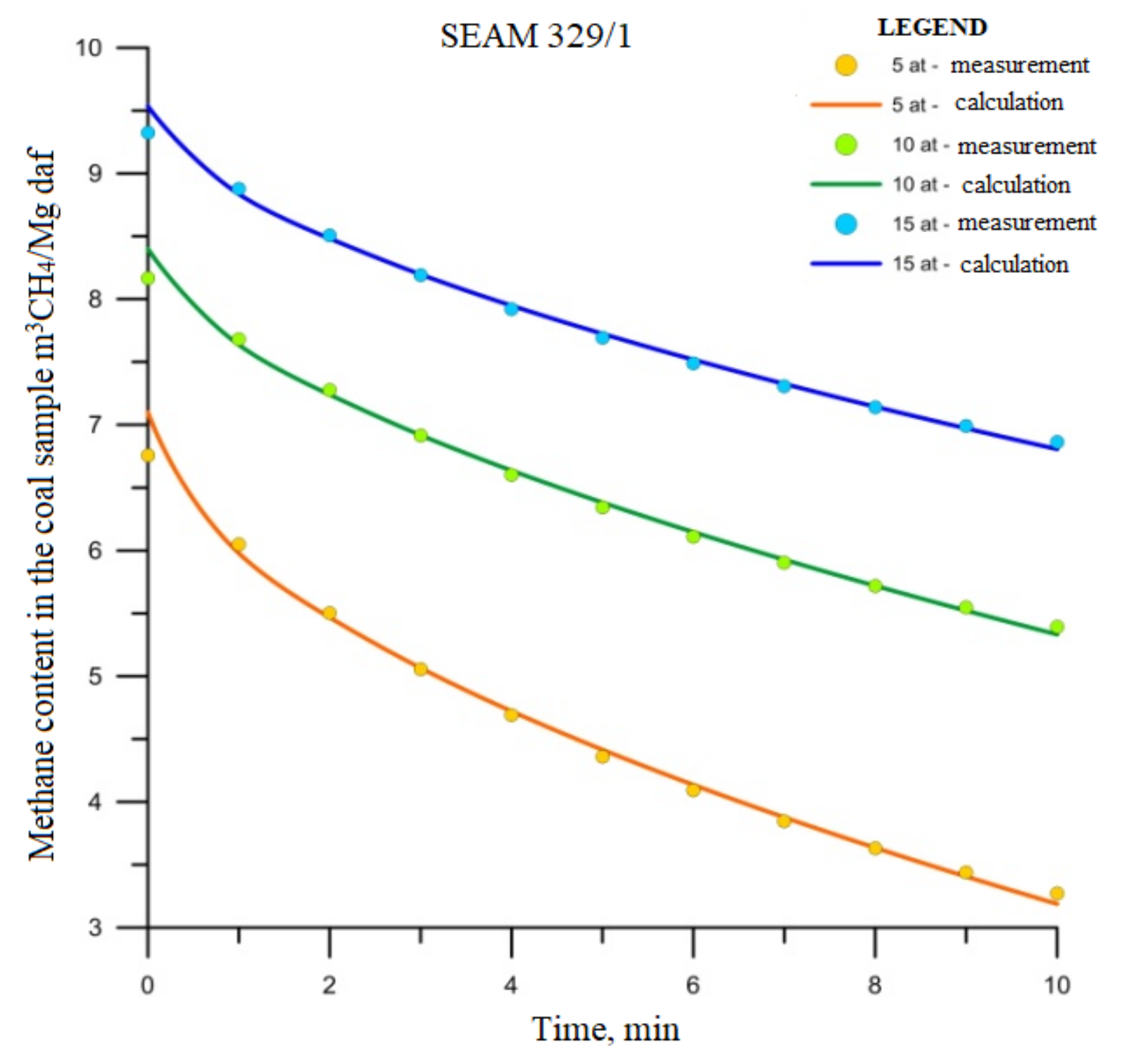
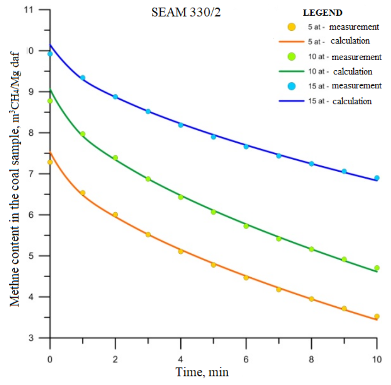
The sorption and desorption of methane into and from coal are essential factors contributing to the assessment of methane hazard in hard coal seams. The awareness of sorption makes it possible to evaluate the gas content present in the deposit and its state. However, desorption, i.e., the process of reversing the consequences of sorption, allows us to calculate the amount of gas desorbed from coal over time. This knowledge is vital from the perspective of mine safety as it enables the identification of spots particularly vulnerable to methane release and eliminates them through intense ventilation.
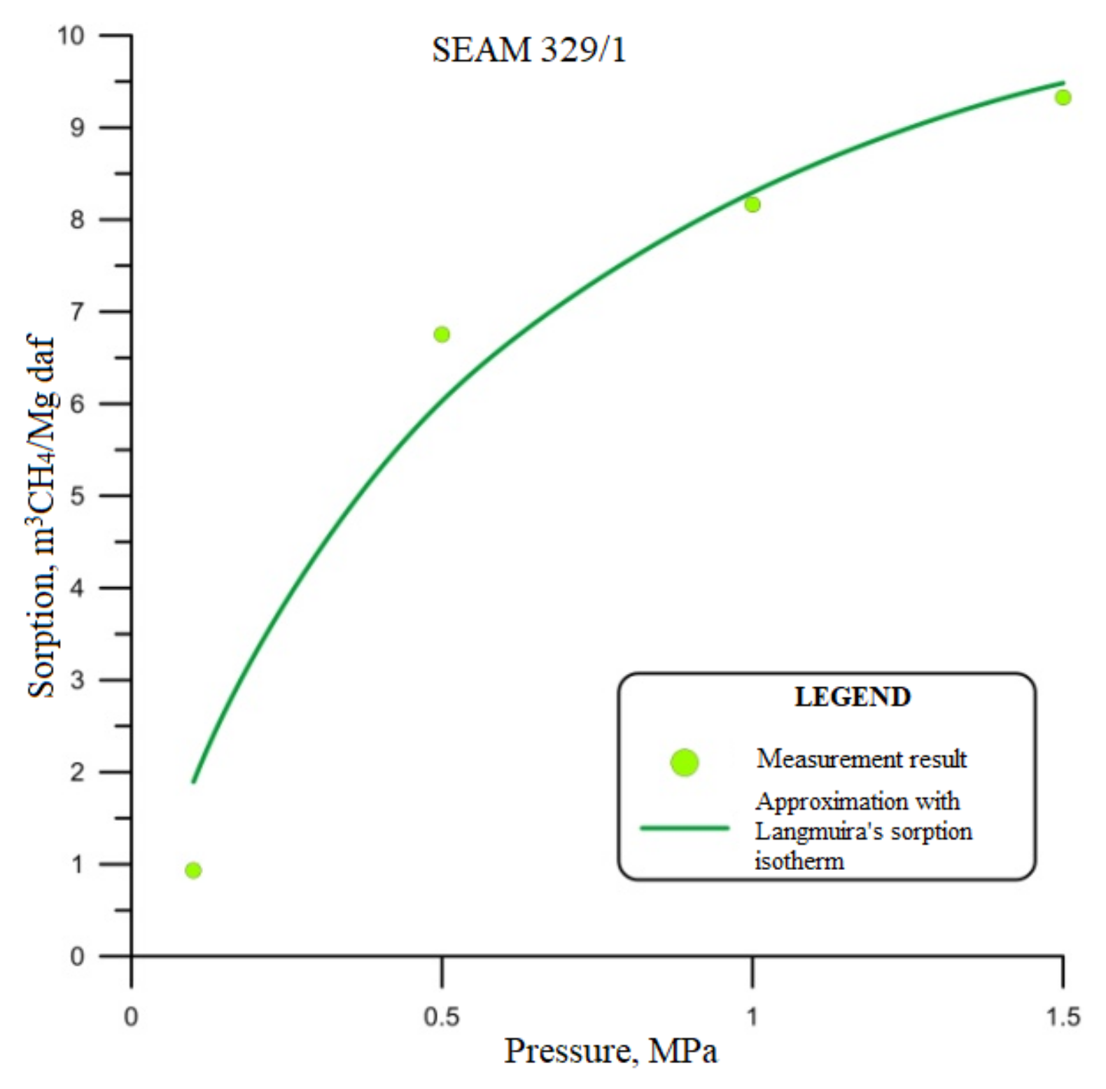
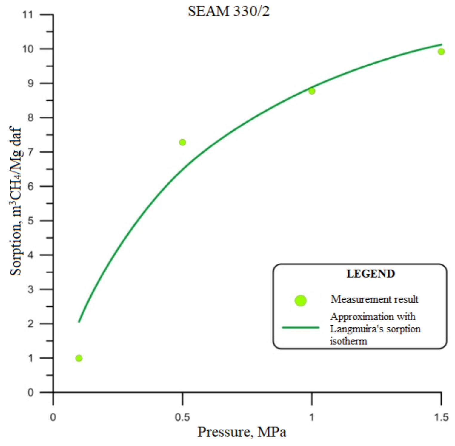
One of the first and most commonly used isotherms is the Langmuir isotherm. Its equation and that of Freundlich isotherm are the most frequently used formulas for analyzing the sorption of CO2, CH4, and N2 in hard coal within the temperature range 293 to 313 K [43,46]. As for desorption, it is an aggregated reverse process that consists of releasing the sorbate from the sorption space.
The sorption of gases is a complex process in which its rate and adsorbed substance depend on time. Kinetic curves reflect the relationship between the amount of adsorbed substance and time. The sorption value evolves towards a limit corresponding to an equilibrium at the given concentration of gas.
Studies conducted in mines involved collecting coal samples for laboratory analysis [47]. They came from various mines and levels of exploitation. The intention while collecting them was to represent multiple coal characteristics, such as hardness, the share of volatile parts, or moisture and ash content. The sampling followed procedures elaborated for the purpose [47], and the analysis included methane adsorbed in coal and methane’s desorption from coal using an IGA-001 analyzer. It is a gravimetric device used to determine the isotherms of sorption and desorption of gases.
2.2. The Amount of Methane in Polish Hard Coal Deposits
The confirmed methane resources are present in 65 deposits in the Upper Silesian Coal Basin (Table 1) [48]. The recoverable balance resources amount to 109.548 bcm, including 68.65 bcm in the extracted areas of 30 developed seams. The resources are currently beyond exploitation, i.e., undeveloped reserve deposits deep-level deposits below 1000 m, amount to 21.36 bcm. The industrial resources in coal deposits under development have been estimated for 33 deposits and amounted to 10.43 bcm.
Methane in Polish deposits occurs in an absorbed form, and its content is strictly dependent on the structure of the rock mass and coal deposits in a given region. In the areas of the Upper Silesian Coal Basin, the highest methane content is located at a depth of −950 to −1050 above sea level.
Methane hazard in hard coal mines determines the rising costs of coal extraction due to the investments needed to implement preventive measures and mitigate the risk. Moreover, the cost of methane drainage is mounting. On the other hand, methane captured by drainage systems can serve as a carrier of energy whose economically sound use can offset drainage costs or even yield profits. Recently, attempts at capturing methane from the surface by drilling boreholes and fracturing the deposits becoming popular. Because of low transmission of coal seams, retrieving methane directly from the underground seams is tedious and ineffective.
2.3. Methane Desorption Zones during Longwall Mining
The extraction of a seam causes decompression and its fracturing and the overlying rocks. As a result, permeability increases substantially, and methane can flow with relatively little obstruction from the decompressed zone into the excavation. The emerging pressure gradient initiates the gas movement towards the excavation, where the pressure is lower than the gas pressure in the rock mass. The release of methane is problematic as it depends on several geological and technical factors [40].
The amount of methane emitted into excavations and into the working in particular, depends on the following values [40]:
- the amount of methane released from the extracted coal (including also the emissions from mined coal and during its transport);
- the amount of methane desorbed from the adjacent seams in the roof and the floor, placed within the zone affected by development.
The adopted roof management method (backfill or caving) and nature or rocks (hard or ductile) determine the range and the scale of rock decompression.
The gas emission into a longwall excavation begins just after decompression of the rock mass. It is primarily released from coal seams, and the process continues through the entire exploitation, which is the leading cause of rock-mass decompression. As the longwall face advances, provoking the seam to recompress, gas flow from the seam slows down and stops. The degree of degasification of the rock mass and coal seams caused by exploitation depends mainly on decompression duration.
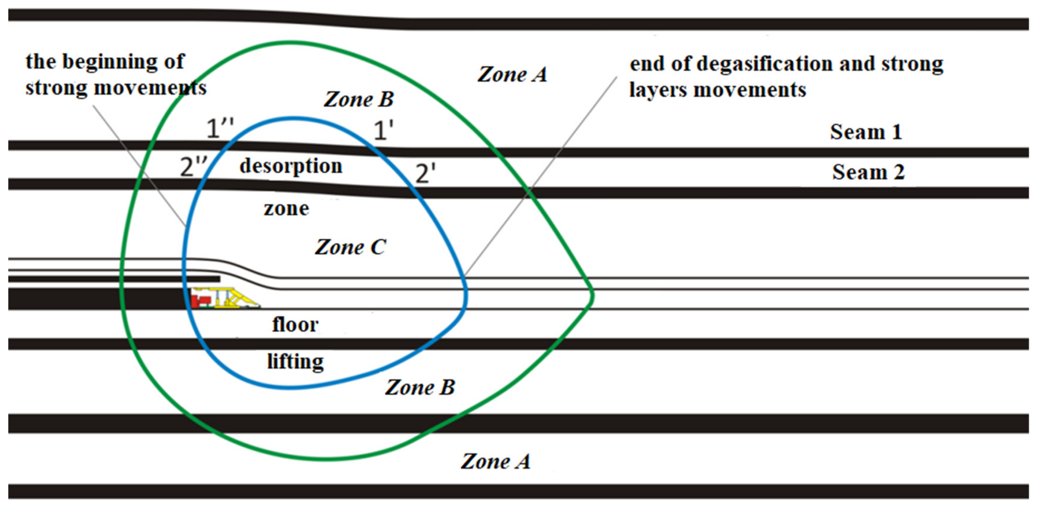
Figure 5 shows a longitudinal section of longwall life to illustrate the effect of exploitation on the adjacent layers’ degasification [28]. The zones of varying influence exerted by exploitation are marked. The figure shows both the area of gas release and the process’s duration for individual layers depending on the developed seam distance.
Figure 5 identifies three zones. Zone A represents the area virtually unaffected by the changing stresses in the rock mass. The permeability of coal to gas in this zone is consistent with the degree of compression correlated with depth. By contrast, Zone B covers an area of pressures increased due to extraction. The permeability of coal decreases as pressures in the seams rise to the level of exploitation pressure. Finally, Zone C is the area decompressed as a result of seam development. The permeability of coal to gas is considerably higher following decompression. In addition to the lowered resistance of solid coal, the more effortless flow of mine gas into the excavation, caused by the fissures and fractures that facilitate gas migration, characterizes Zone C.
Figure 5 highlights the influence of the duration of decompression of particular layers (coal seams) on their degree of degasification. In a seam permeable to gas, characterized by varying gas pressure values in the seam, gas flow between two points will continue until reaching an equilibrium. The degree of degasification will depend on how long the seam remains decompressed; the amount of gas flowing into the excavation will depend on flow resistance. The higher pressure caused by exploitation is present in the layers close to the developed seam and a part of its goafs, prevalent in Zone B. This zone progresses along with exploitation. As a result, the seams situated further from the developed seam (e.g., seam l as compared with 2) spend less time in Zone C (section l′–l″ is shorter than section 2′–2″). A higher flow resistance, a longer distance of gas flow, and a shorter gas release period mean that the degree of degasification is minor in layers further from the developed seam.
During longwall life, a higher level of methane release occurs after the first caving. The area of methane release grows along with the decompressed zone. In new longwalls, the initial phase of extraction typically is characterized by lower methane-bearing capacity and is determined only by methane from the extracted seam. The first caving may cause a sudden increase in methane emissions and further rise at the initial section of longwall life, correlated with the growth of the decompressed zone. Later on, methane conditions tend to stabilize, provided that the structure of coal seams is regular.
The exploited seam accounts for a significant part of released methane, which is proportional to the coal output. On the other hand, in the overlying and underlaying seams, the amount of methane is described by an exponential relationship.
The shape of the space, in which the degree of the adjacent layers’ degasification (in a plane perpendicular to extraction direction) is affected by mining, greatly influences the amount of release. In the existing forecasting methane release methods, the authors differ in their assumptions concerning the shape of the space affected in a plane perpendicular to the extraction direction. Thus, the beliefs vary in the range and degree of degasification of the particular layers [9,29,40].
In real conditions, a specific field of gas pressures and gas-bearing capacity characterize a deposit. As a result of employing a particular exploitation method, a characteristic range of rock-mass disruption emerges, with gas-bearing capacity fluctuations.
Extraction of the seam and depressurizing it through exploitation are factors causing a new pressure field to shape the rock mass. It may affect the degree of degasification of coal seams extracted during another longwall development. Assuming a steady level of degasification regarding the overlying and underlying seams is an error that leads to inaccurate forecasts of methane release into excavations.
3. Desorption of Methane from Hard Coal Seams
The geological conditions determining the presence of methane in coal deposits and the low permeability of coal seams in Poland mean that methane release other than caused by a disruption of rock mass through mining activity is minimal. That way, the emission of methane is closely correlated with the intensity of the mining works performed such as development and proper coal deposit extraction [29,49].
The mining system most frequently used in Polish mines is a longwall system, which allows obtaining a quite high amount of coal extracted and significant longwall advance [50]. The high methane content in seams is enforced using methane drainage systems during mining. There is a wide range of factors when selecting a proper methane drainage system, and Polish hard coal mines have used many of them during longwall mining.
Rock-mass methane drainage is the best way to reduce methane emissions to workings and prevent coal outbursts. The principle of methane drainage is to capture methane from the rock mass and isolated goafs through a system of specially designed boreholes and then transport it to the surface drainage station. This method helps to keep the required ventilation parameters on the same level. Still, at the same time, it imposes individual requirements as to the ways longwall panels develop in gassy seams. In Polish mines, pre-mining drainage is used only rarely due to low coal permeability resulting in low effectiveness.
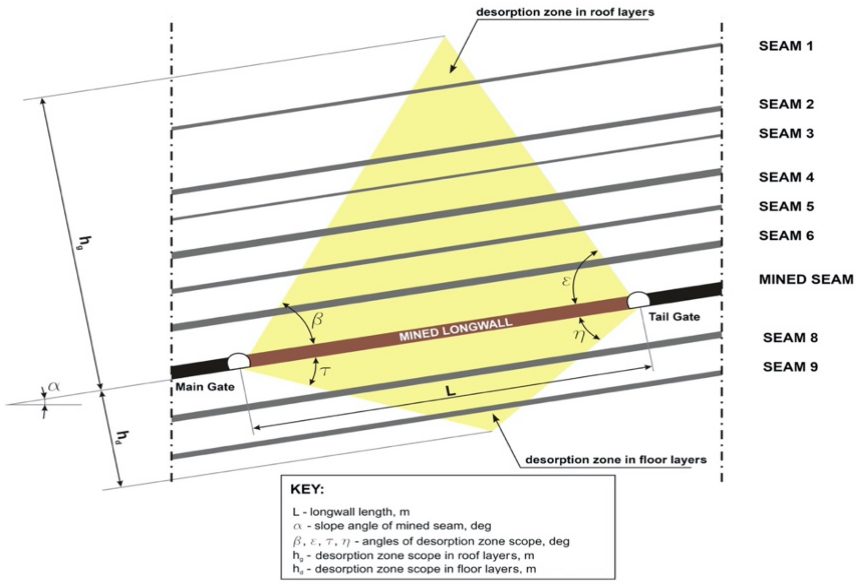
In the methane drainage of nearby seams (overlaying and underlying), it is necessary to determine a desorption zone (gas emission zone) caused by longwall mining [29,30]. The drainage boreholes should be placed in an unstressed zone, but they should not pass through the area of immediate roof caving. In Polish geological conditions, achieving good results is possible while determining drainage boreholes’ slope angles following Flügge 1971 [51] (Figure 6).
Values given in Figure 6 correspond to boreholes drilled parallel to a longwall face [37]. A borehole’s slope angle corresponds approximately to an angle of desorption zone scope in such a case. Drilling sloping boreholes askew to a longwall face needs to adopt a particular assumption. Suppose drilling boreholes from a parallel entry. In that case, angle determination must include a pillar’s width between entries. It is also essential to remember placing that the longest part of a borehole in an unstressed zone.
The borehole length depends on geological conditions and, above all, on the localization of underlying and overlaying seams [37]. All drilled boreholes ought to pass through all seams in gas emission space. The length of the longwall L is also crucial as the height of the calculated desorption zone depends on it.
Assuming designations as in Figure 5, calculation for the roof layers can follow the Formula (1) [37,38]:
where:
- β and ε-are angles of the desorption zone, deg.
For the perpendicular plane area of degasification, as presented in Figure 6, sloping angles of a desorption zone to a seam plane will amount to (2) and (3):
for a head entry
and for a tail entry
where:
- α-slope angle of a mined seam, deg.
Supposing that the mined seam’s slope angle does not exceed 50 deg of the value of the desorption angles, one can assume the value of the desorption angles δd and δg (calculated regarding the horizontal plane) according to Table 2.
For floor layers, we assume opposite angles. For the floor layers, half the value of the desorption angles is assumed due to the lower inflow than established for the desorption zone:
In the the above equations follow that:
- -
- the seam located in the roof at a distance “a”, m
- -
- or the floor at a distance “b”, m
are affected by the exploitation along the length X depending on the length L of the longwall.
Then, calculation can follow the formula below (7) and (8):
where:
The above calculations (7) and (8) assume that distances a and b are perpendicular to the seam plane. While drilling drainage boreholes to adjacent seams, the boreholes’ slope angle should remain in the established desorption zone.
While using the methods outlined above, we work on the assumption that coal seams are the primary source of methane release, although release from barren rocks, e.g., sandstone, is also considered.
The assumed space of gas release, situated within a mined longwall, is presented as a simple geometric form. It is referred to as the ‘desorption zone’ and is used as a reference point to determine the amount of released gas depending on the mined seam’s distance. Typically, the released amount depends on the amount initially present in the seam (methane content). The release rate from specific coal seams and the amount of gas flowing into excavations depend on the amount of methane in the seam and the coal output at a given longwall.
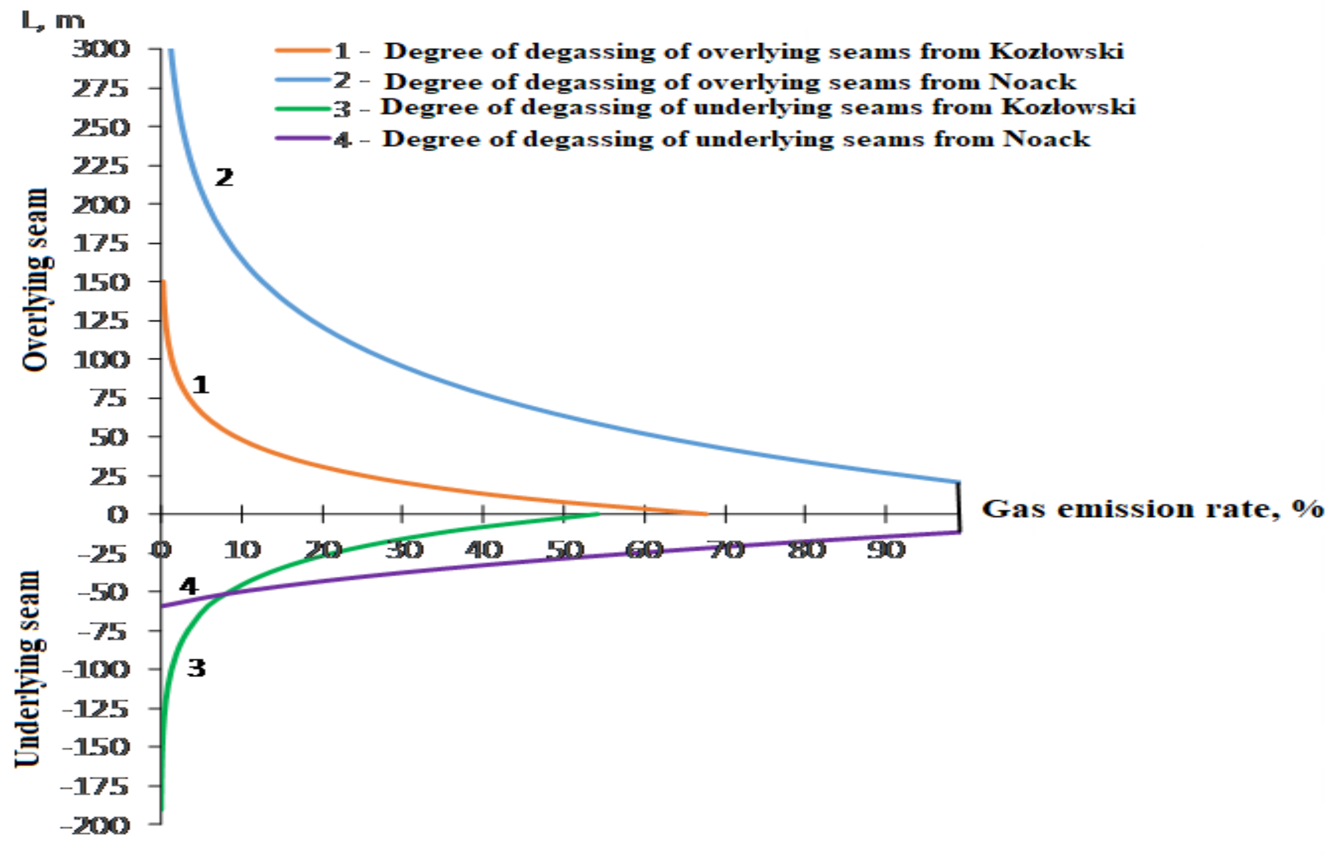
The amount of gas released from the overlying and underlying seams is determined using an empirical equation. The practical limits for calculations were 165 m for the roof and 59 m for the floor. Table 3 presents the relationships making it possible to identify the degree of seam degasification affected by mining, according to Noack (1998) and Kozłowski (1982). Figure 7, on the other hand, shows the degasification curves. Considering the thickness of 1.0 m for the mined layer, the authors mentioned above could determine the degree of methane drainage from seams. In Figure 6, we see differences in the degree to which the seams were degasified, resulting from the input data accepted by the authors mentioned above.
The mining and geology conditions found in a given coal basin influence the degree of methane drainage of seams disrupted by exploitation.
where:
- l—actual distance, m
- me—thickness of the mined seam, m
- α—coefficient related to the management of waste areas, which is:
- for caving α = 1
- for dry backfilling α = 0.3–0.5
- for hydraulic filling with barren rock α = 0.2–0.4
- for hydraulic filling with sand α = 0.05–0.15.
- Lu—an actual distance of a given seam from the mined seam, m
In the Formula (11), L assumes positive values of overlying seams and negative values of underlying seams.
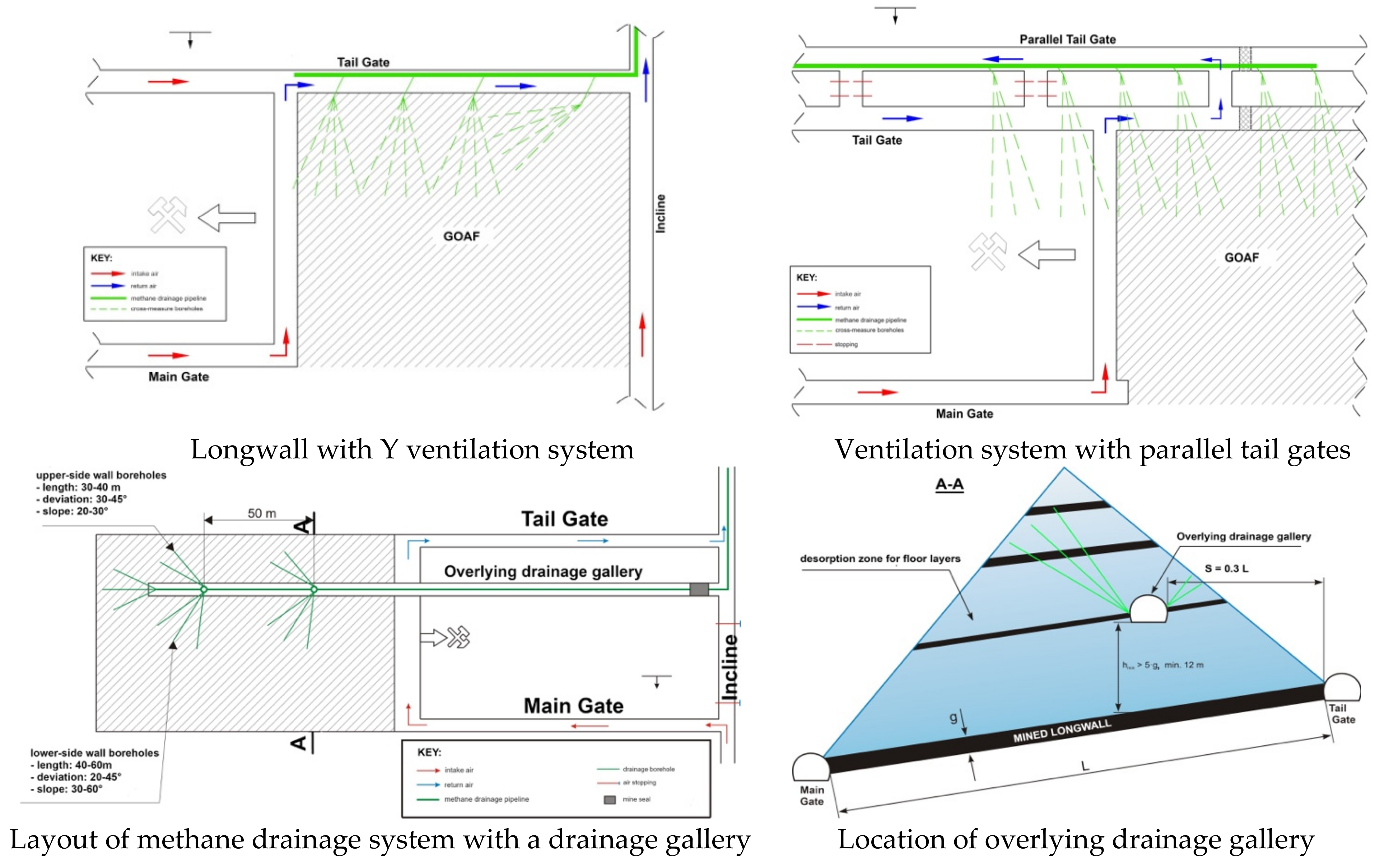
Under the Polish mining industry conditions, to increase the methane capture at the operational stage, different methane drainage systems are used depending on the forecast of total methane emissions and the ventilation system. Figure 8 shows the methane drainage systems commonly used in the Polish mining industry. Their exact description can be found in the literature [37,38,39,40,41].
Table 4 shows the average efficiency of methane drainage in Polish coal mines depending on total methane emissions at the longwall panel. The data show that the lowest value of methane drainage efficiency was obtained for the “U” ventilation system (41.2%), and the highest with the use of systems with parallel tailgates and an overlaying drainage gallery were 63.9% and 63.4%, respectively. The average methane drainage efficiency over ten years was 54%.
4. An Example of Methane Capture during Operation with the Overlying Drainage Gallery
To present the influence of methane drainage system selection on the efficiency of methane capture, the example of the longwall B-15 in seam 348 is presented. The coal mine under discussion is placed in the southwestern part of Upper Silesia Coal Basin and belongs to the biggest coal producer in Poland—JSW Group. The coal mine is also considered to be one of the most gas-prone coal mines in Poland.
4.1. Research Objectives
The results obtained during the exploitation of the B-15 longwall illustrate the methane capture during operation. The considered B-15 longwall was operated inseam 348 with the field collapse system. Figure 9 shows a fragment of the seam 348 with the B-15 longwall marked, and Figure 10 a scheme of the excavations in the longwall area. Technical parameters of the B-15 longwall and existing natural hazards are presented in Table 5.
4.2. Description of Mining and Geological Conditions in Area of the B-15 Longwall in Seam 348
The area of the B-15 longwall in seam 348 was identified by the B-15 heading, the B-15 ventilation heading, and from the surface. Data obtained from geological boreholes drilled from the surface and mining excavations were used to identify the roof and floor layers. The thickness of the coal seam identified within the boundaries of the planned pilot of the B-15 longwall and the clay overgrowths ranged from 1.80 to 3.80 m.
In the top layers of the coal seam in the area of the B-15 longwall, there are layers of loam and sandy loam. The bottom layers are the clay, sandy, and sandy loam. Exploration was carried out from 930 to 1050 m. The seam slope measured in the longwall headings is from 13 to 20 deg.
While preparing the longwall workings for the designed B-15 longwall, geological disturbances in the form of faults with the discharge amplitude ranging from 0.3 to 2.8 m were found. The projected course of fault planes is presented in Figure 8.
Above the planned longwall panel, inseam 348, the operation was carried out in:
- seam 326/1 distant by about 610 m;
- seam 327/3 distant by 580 m;
- seam 328/1 distant by 545 m;
- seam 329/2 distant by 510 m;
- seam 330/1 at a distance of 480 m;
- seam 333/1 at a distance of 410 m.
There was no exploitation in the lower decks.
4.3. System of Ventilation for the B-15 Longwall Inseam 348
The longwall B-15 in seam 348 was ventilated with the “U” ventilation system. Intake air was brought via shaft I and II and then delivered to the longwall in three ways:
- The intake airflow through the haulage drift to the shaft I located at a depth of about 830 m and then through a glade to the haulage drift to shaft I, down to the inclined drift B-1, through the B-1 inclined drift, transport glade B-15, and the B-15 holding heading. Then, through the B-15 heading in seam 348, the air was directed to the longwall B-15 in seam 348.
- From level 820, air flew along the heading to the shaft I, along the main heading in seam 340, and then along the haulage slope to the haulage drift N. Next, along the B-11 heading, the B-15 transport heading, and the B-15 heading was directed to the B-15 longwall in the seam 348;
- From level 620, air flew:
- -
- from the shaft I through the skip circuit of empty wagons, through the belt collecting drift to the haulage drift N,
- -
- from the shaft II with the cage circulation of empty trucks, with the technological drift inseam 620 from where it flew:
- through the skip circuit of empty wagons and collective belt drift to the N haulage drift,
- through the skip circuit of empty carts, with a glade to the haulage drift N and along it, and further along heading B-11, transport heading B-15, and then heading B-15 to longwall B-15 inseam 348.
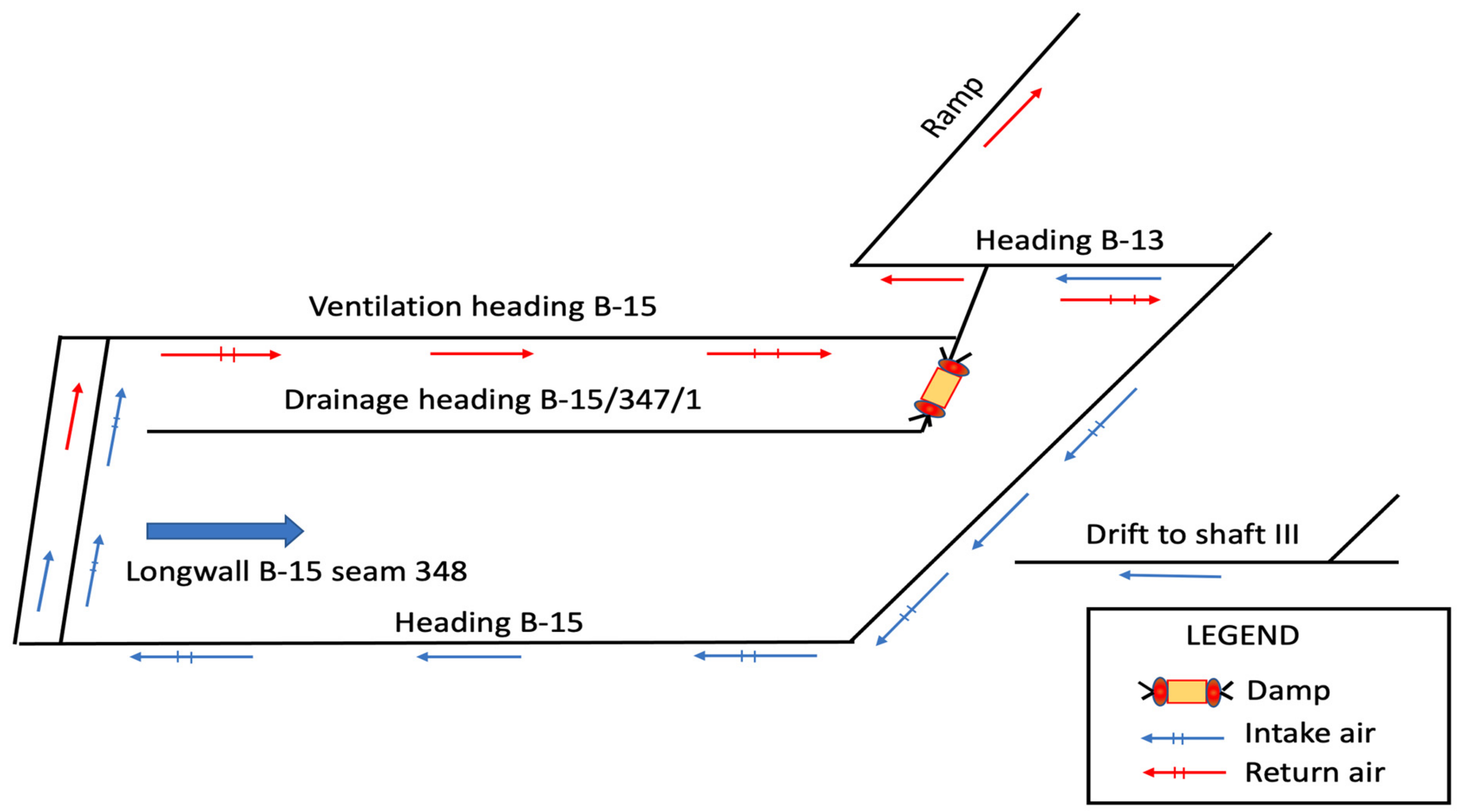
The return air from the B-15 longwall was discharged through the B-15 ventilation heading in seam 348, the B-15 drainage gallery in seam 347/1, the B-13 heading, the B-5 and B-13 ramp, and then transport haulage B-13, and research heading B-9 in seam 348. Then, it was directed to the drift B at level 620, through the eastern section drift on level 620 to the shaft III.
5. Results and Discussion
The methane content of seam 348 decreases from east to west—that is, from the point where the longwall excavation begins towards the point where it ends. The distribution of methane content showed that its value varied from 9.743 to 7.060 m3/Mgdaf. The range of methane desorption for the B-15 longwall was determined as:
- to the roof layers—155 m;
- to the floor layers—58 m.
In the profile of methane content layers in the degasification zone, there were 17 seams and carbon layers in the roof and nine seams and carbon layers in the floor. The methane content was determined only inseam 348 on the B-15 longwall contour and partially in 1983–1988 inseam 340 lying about 180 m above and below. No methane content determinations were carried out in the remaining seams above and below. Table 6 presents the forecasted methane release for the 100 m long section of the longwall B-15. It ranged between 59 m3/min for the 2.5 m/d face advance to over 61 m3/min for 3.8 m/d face advance.
Due to forecasted methane release, it was decided that for the planned extraction and face advance:
- 1400 m3/min of fresh air should be supplied to the B-15 longwall;
- an additional 350 m3/min should be supplied to the longwall outlet.
The forecasted methane release indicated that to ensure safe operation of the B-15 longwall, with the assumed production of 1800 to 2800 Mg/d and given the conditions prevailing in the longwall, it was not possible to carry out mining operations without methane drainage. Based on the forecasts, it was assumed that the methane drainage efficiency should be 70%. Considering the data on the effectiveness of the methane drainage presented in Table 4, the best results are achieved using methane drainage with an overlaying gallery. Such a system was also used to carry out the safe operation in the B-15 longwall despite its associated huge financial outlays.
The methane drainage of the B-15 longwall was carried out based on the “Technical design of the B-15 longwall drainage inseam 348”. The methane drainage of the longwall was carried out with the use of the B-15 drainage gallery in seam 347/1, made over the longwall exploitation field, and through methane boreholes drilled from this gallery (see Figure 10). Insulating damp was made in the B-15 drainage heading. The access to the cork in the B-15 drainage heading was ventilated using a pneumatic duct fan.
Methane captured from the B-15 longwall was discharged through two 400 mm methane pipelines built in the B-15 drainage heading in seam 347/1 and further on the levels 620 and 820 m and then to the shaft III.
The methane pipelines were connected by a pipeline section with the diameter of 300 mm with an installed valve with the diameter of 300 mm in the B-15 drainage floor in seam 347/1, which enabled the regulation of the flow of the captured gas mixture.
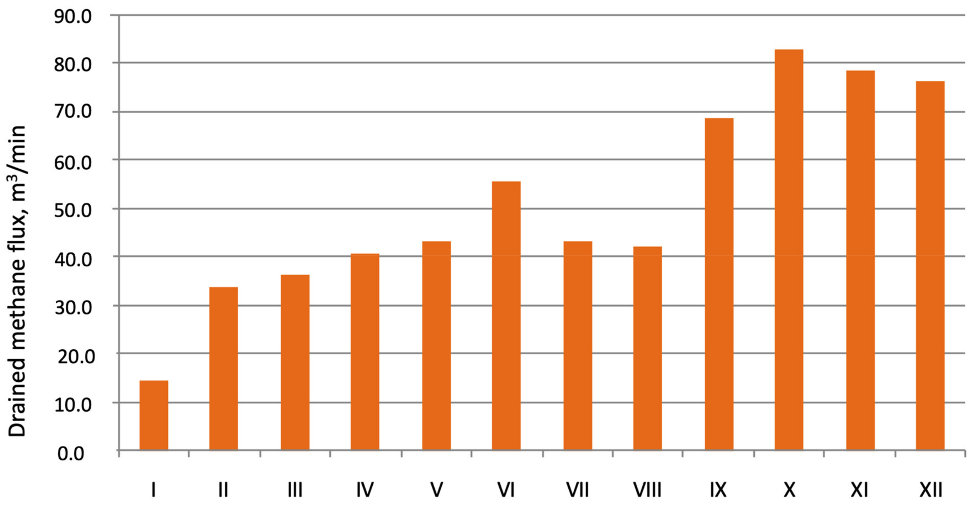
Figure 11 shows the changes of captured methane during the exploitation of the B-15 longwall. In the first month of exploitation, methane capture was about 15 m3/min. Its value increased to 55 m3/min in the next five months, which was expected while looking at the forecasted methane release (Table 6). In July and August, methane release dropped slightly to the above 40 m3/min. What is most striking is that from September, methane capture increased drastically above forecasted values. The highest value was recorded in October and reached 82 m3/min.
The designed ventilation system for the discussed longwall with methane drainage provided for the capture of 70% of the forecasted methane release, i.e., about 40 m3/min. The applied methane drainage system allowed capturing almost twice as much methane.
This particular example of the longwall shows that it is crucial to properly design the drainage system for seams with high forecasted methane release. Using a system with an overlying drainage gallery allows capturing methane with higher efficiency. It is worth remembering that the use of this particular system provides an increase in the methane capture from the desorption zone areas. If a different system was used, the methane emissions would not be so high.
6. Conclusions
It is crucially important to choose an adequate drainage system and the parameters of drainage boreholes to the shape of the decompressed zone, evolving with the advancing longwall. It will allow achieving high efficiency of methane capturing from coal seams. The shape of the space, in which the degree of the adjacent layers’ degasification (in a plane perpendicular to extraction direction) is affected by mining, dramatically influences the release amount. In natural conditions, a specific field of gas pressures and gas content characterize the deposit. As a result of employing a particular exploitation method, a characteristic range of rock-mass disruption emerges, with gas emission fluctuations.
The authors have highlighted, in the example of the longwall B-15, that using the drainage gallery allowed to capture twice the amount of methane forecasted, thus increasing the efficiency of methane drainage. At the preliminary stage of longwall development, the amount of methane charged by the drainage system had relatively low values reaching 15 m3/min. In the next few months, these parameters increased and varied between 35 to 55 m3/min. A significant difference in methane capture appeared in the second stage of exploitation, where the highest value of captured methane reached 82 m3/min.
The adequately designed methane drainage system for the B-15 longwall in seam 348 allowed capturing 70% of the forecasted methane, i.e., about 40 m3/min. The example under discussion showed that while planning the exploitation of a particular seam or a longwall panel, the height of the desorption zone caused by mining should be defined. Then, it is possible to drain methane from adjacent seams. The usage of a system with an overlying drainage gallery allowed capturing methane with higher efficiency. It is worth remembering that this particular system provides an increase in methane capture from the desorption zone areas. If a different approach were used, the methane emissions would not be so high.
Author Contributions
N.S. developed a concept and methodology for the presentation of research results. J.S. contributed analysis tools, analyzed data, and wrote the paper. Both authors have read and agreed to the published version of the manuscript.
Funding
The article was prepared as part of the Subsidy for the Maintenance and Development of Research Potential at Faculty of Civil Engineering and Resource Management AGH University of Science and Technology No. 16.16.100.215.
Institutional Review Board Statement
Not applicable.
Informed Consent Statement
Informed consent was obtained from all subjects involved in the study.
Data Availability Statement
Upon authors’ request.
Conflicts of Interest
The authors declare no conflict of interest.
References
- Noack, K. Control of gas emissions in underground coal mines. Int. J. Coal Geol. 1998, 35, 57–82. [Google Scholar] [CrossRef]
- Noack, K.; Opahle, M. Progress achieved in the prediction of gas emission. In Proceedings of the 5th International Mine Ventilation Congress, Johannesburg, South Africa, 25–30 October 1992; Volume 5, pp. 79–87. [Google Scholar]
- Creedy, D.P. Methane Prediction in Collieries; Report SIMRAC; CSIR: Delhi, India, 1996. [Google Scholar]
- Ren, T.X.; Edwards, J.S. Application of CFD techniques to methane prediction and control in coal mines. In Proceedings of the 27th International Symposium on Computer Applications in the Mineral Industrie, Kalgoorlie, Australia, 7–9 December 1998; pp. 733–743. [Google Scholar]
- Kesley, A.; Lea, C.J.; Lowdnes, I.S.; Whittles, D.; Ren, T.X. CFD modelling of methane movement in mines. In Proceedings of the 30th International Conference on Safety in Mines Research Institutes, Johannesburg, South Africa, 5–9 October 2003; p. 30. [Google Scholar]
- CEC. Short-Term Forecasting of Methane Emission Levels Using Brussels, Belgium Continuously Monitored Data; Final Report on ECSC Contract 7220 –AC/832; European Communities: Brussels, Belgium, 1989. [Google Scholar]
- Dixon, D.W.; Longson, I. A statistical method for methane prediction and improved environmental control. In Proceedings of the 6th US Mine Ventilation Symposium, Salt Lake City, UT, USA, 21–23 June 1993; p. 6. [Google Scholar]
- Tauziede, C.; Pokryszka, Z. Dynamic prediction of methane emission at longwalls. In Proceedings of the International Conference of Safety in Mines Research Institutes, Pretoria, South Africa, 13–17 September 1993; p. 25. [Google Scholar]
- CEC. Prediction of Gas Emission on Short Faces and Drivages; Final Report on ECSC, Contract 7220-AC/834; HSE: Bootle, Merseyside, UK, 1992.
- Karacan, C.Ö. Forecasting gob gas venthole production performances using inteligent Computing. Int. J. Coal Geol. 2009, 79, 131–144. [Google Scholar] [CrossRef]
- Łunarzewski, L. Gas emission prediction and recovery in underground coal mines. Int. J. Coal Geol. 1998, 35, 117–135. [Google Scholar] [CrossRef]
- Łunarzewski, L. A model of gas release. In A Programme Manual; Lunagas Pty Ltd.: Newcastle, UK, 2005. (In Polish) [Google Scholar]
- Karacan, C.Ö. Development and application of reservoir models and artificial neural networks for optimising ventilation air requirements in development mining of coal seams. Int. J. Coal Geol. 2007, 72, 221–239. [Google Scholar] [CrossRef]
- Karacan, C.Ö. Modeling and prediction of ventilation methane emissions of U.S. longwall mines using supervised artifi cial neural networks. Int. J. Coal Geol. 2008, 73, 371–387. [Google Scholar]
- Karacan, C.Ö. Evaluation of the relative importance of coalbed reservoir parametres for prediction of methane infl ow rates during mining of longwall developmententries. Comput. Geosci. 2008, 34, 1093–1114. [Google Scholar] [CrossRef]
- Dixon, D.W.; Ozveren, C.S.; Sapulek, A.T.; Tuck, M.A. The application of neural networks to underground methane prediction. US Mine Vent. Symp. 1995, 7, 49–54. [Google Scholar]
- Borowski, M.; Szlązak, N.; Obracaj, D. Ocena Stężenia Metanu w Zrobach Ścian Zawałowych na Podstawie Prowadzonych Pomiarów. Mater. Szkoły Eksploat. Podziemnej 2005, Szczyrk 21–25 February, Kraków. Available online: http://szkolaeksploatacji.pl/referat/ocena-stezenia-metanu-w-zrobach-scian-zawalowych-na-podstawie-prowadzonych-pomiarow/ (accessed on 13 June 2021). (In Polish).
- Roszkowski, J.; Szlązak, N. Selected Problems of Methane Drainage in a Coal Mine; Uczelniane Wydawnictwa Naukowo-Dydaktyczne: Kraków, Poland, 1999. (In Polish) [Google Scholar]
- Szlązak, N.; Korzec, M. Zagrożenie metanowe oraz jego profilaktyka w aspekcie wykorzystania metanu w polskich kopalniach węgla kamiennego. Górnictwo I Geoinżynieria 2010, 34, 163–174. [Google Scholar]
- Skotniczy, P. Three-dimensional numerical simulation of the mass exchange between longwall headings and goafs, in the presence of methane drainage in a U-type ventilated longwall. Arch. Min. Sci. 2013, 58, 705–718. [Google Scholar]
- Brunner, D.J.; Schwoebel, J.J.; Brinton, J.S. Modern CMM drainage strategies. In Proceedings of the First Western States CMM Recovery and Use Workshop, Sardinia, Italy, 19–20 April 2008. [Google Scholar]
- C.R.—Collective review: Brzeszcze Mine—Yesterday and Today. In Brzeszcze; Coal Mine Staff (Ed.) Beskidzka Press Publisher: Brzeszcze, Poland, 2003. (In Polish) [Google Scholar]
- Creedy, D.P.; Kershaw, S. Firedamp prediction—A pocket calculator solution. Min. Eng. 1988, 2, 377–379. [Google Scholar]
- De Villiers, A.W. Methane drainage in longwall coal mining. J. S. Afr. Inst. Min. Metall. 1989, 89, 61–72. [Google Scholar]
- Diamond, W.P. Methane Control for Underground Coal Mines. In Information Circular; U.S. Bureau of Mines, IC 9395; United States Department of the Interior: Washington, DC, USA, 1994. [Google Scholar]
- Fang, Z.; Li, X.; Wang, G.G.X. A gas mixture enhanced coalbed methane recovery technology applied to underground coal mines. J. Min. Sci. 2013, 49, 106–117. [Google Scholar] [CrossRef]
- Karacan, C.Ö.; Ruiz, A.F.; Cotè, M.; Phipps, S. Coal mine methane: A review of capture and utilization practices with benefits to mining safety and to greenhouse gas reduction. Int. J. Coal Geol. 2011, 86, 121–156. [Google Scholar] [CrossRef]
- Kissel, F.N. Handbook for Methane Control in Mining; National Institute for Occupational Safety and Health: Pittsburgh, PA, USA, 2006.
- Krause, E.; Łukowicz, K. Methane drainage in Polish hard coal mines. Achievements and perspectives. In Proceedings of the 11th International Scientific and Technical Conference “Rockbursts 2004”: New Solutions in the Field of Preventing Rockbursts and Methane Hazards, Ustroń, Poland, 8–10 November 2004. (In Polish). [Google Scholar]
- Szlązak, N.; Kubaczka, C. Impact of coal output concentration on methane emission to longwall faces. Arch. Min. Sci. 2012, 57, 3–21. [Google Scholar]
- Szlązak, N.; Borowski, M.; Obracaj, D.; Swolkień, J.; Korzec, M. Effectiveness of coal mine methane drainage in Polish mines. In Proceedings of the Twenty-ninth Annual International Pittsburgh Coal Conference: Coal—Energy, Environment and Sustainable Development, Pittsburgh, PA, USA, 15–18 October 2012. [Google Scholar]
- Whittles, D.N.; Lowndes, I.S.; Kingman, S.W.; Yates, C.; Jobling, S. The stability of methane capture boreholes around a longwall coal panel. Int. J. Coal Geol. 2007, 71, 313–328. [Google Scholar] [CrossRef]
- Schatzel, S.J.; Karacan, C.Ö.; Krog, R.B.; Esterhuizen, G.S.; Goodman, V.R. Guidelines for the Prediction and Control of Methane Emissions on Longwalls; Information Circular No. 9502; U.S. Department of Health and Human Services, Centers for Disease Control and Prevention, National Institute for Occupational Safety and Health: Pittsburg, PA, USA, 2008.
- Black, D.J.; Aziz, N.I. Developments in coal mine methane drainage and utilization in Australia. In Proceedings of the Ninth International Mine Ventilation Congress, New Delhi, India, 10–13 November 2009; pp. 445–460. [Google Scholar]
- Wang, L.; Cheng, Y.P. Drainage and utilization of Chinese coal mine methane with a coal–methane co-exploitation model: Analysis and projections. Resour. Policy 2012, 37, 315–321. [Google Scholar] [CrossRef]
- Hongxing, Z.; Hao, D.; Chungui, G. Quality and quantity of pre-drainage methane and responding strategies in Chinese outburst coal mines. Arab. J. Geosci. 2016, 9, 445. [Google Scholar] [CrossRef]
- Szlązak, N.; Borowski, M.; Swolkień, J. The Effectiveness of Methane Drainage of the Rock-Mass with a Parallel Ventilation Heading during Longwall Mining. J. Energy Power Eng. 2014, 8, 1876–1888. [Google Scholar]
- Szlązak, N.; Swolkień, J.; Obracaj, D. Methane drainage from roof strata using an overlying drainage gallery. Int. J. Coal Geol. 2014, 136, 99–115. [Google Scholar] [CrossRef]
- Szlązak, N.; Swolkień, J.; Obracaj, D. Possibilities of increasing the Effectiveness of Mining Methane Drainage in Condition of Low Permeability of Coal Seams. J. Energy Power Eng. 2014, 8, 1167–1176. [Google Scholar]
- Szlązak, N.; Borowski, M.; Obracaj, D.; Swolkień, J.; Korzec, M. Methane Drainage from Strata in Coal Mines; Wydawnictwa AGH: Kraków, Poland, 2015. (In Polish) [Google Scholar]
- Swolkien, J. Utilizing of methane from Polish hard coal mines. J. Energy Power Eng. 2015, 9, 149–160. [Google Scholar] [CrossRef]
- Kotarba, M. Geomechaniczne kryteria genezy gazów akumulowanych w serii węglonośnej górnego karbonu niecki wałbrzyskiej. Zesz. Nauk. AGH 1998, 1119, 19. (In Polish) [Google Scholar]
- Czapliński, A. Węgiel Kamienny; Wydawnictwo AGH: Kraków, Poland, 1994. [Google Scholar]
- Gan, H.; Nadi, S.P.; Walker, P.L. Nature of the porosity in American Coals. Fuel 1972, 51, 272. [Google Scholar] [CrossRef]
- Lasoń, M.; Żółcińska-Jezierska, J. Wyznaczanie mezoporowatości węgli kamiennych z pomiarów adsorpcji argonu w temperaturze ciekłego azotu. Zesz. Nauk. AGH 1984, 963, 1. [Google Scholar]
- Kroger, C.; Bakenecker, I. Die physikalischen und chemischen Eignschafen der Ste- inkohlengefugebestandteile (Macerale). cz. II. Brennst. Chem. 1975, 38, 82. [Google Scholar]
- Szlązak, N.; Borowski, M.; Obracaj, D.; Swolkień, J.; Korzec, M. Metoda Oznaczania Metanonośności w Pokładach Węgla Kamiennego; Wydawnictwa AGH: Kraków, Poland, 2011. (In Polish) [Google Scholar]
- Państwowy Instytut Geologiczny (PIG). Bilans Zasobów Kopalin i Wód Podziemnych w Polsce wg Stanu na Dzień 31.12.2019 r; Polish Geological Institute: Warszawa, Poland, 2020. (In Polish) [Google Scholar]
- Berger, J.; Markiewicz, J.; Dołęga, T. Influence of Distance of Exploitational Front from Drainage Boreholes on their Efficiency with Use the U Ventilation System. Arch. Min. Sci. 2010, 55, 561–571. [Google Scholar]
- Szlązak, N.; Borowski, M.; Obracaj, D. Kierunki zmian w systemach przewietrzania ścian eksploatacyjnych z uwagi na zwalczanie zagrożeń wentylacyjnych. Gospod. Surowcami Miner. 2008, 24, 201–214. (In Polish) [Google Scholar]
- Flügge, G. Die Anwendung der Trogtheorie auf den Raum der Zusatzausgasung. Glückauf Forchungshefte 1971, 32, 337–341. [Google Scholar]
- Kozłowski, B.; Grębski, Z. Odmetanowanie Górotworu w Kopalniach; Wydawnictwo “Śląsk”: Katowice, Poland, 1982. (In Polish) [Google Scholar]
Figure 1.
Isotherm of sorption (seam 329/1).

Figure 2.
Isotherm of sorption (seam 330/2).

Figure 3.
Isotherm of desorption (seam 329/1).

Figure 4.
Isotherm of desorption (seam 330/2).

Figure 5.
The influence of exploitation on the degasification of adjacent layers (adapted from [28]).
Figure 5.
The influence of exploitation on the degasification of adjacent layers (adapted from [28]).

Figure 6.
Diagram illustrating the designation of the desorption zone for the longwall in operation (adapted from [51]).
Figure 6.
Diagram illustrating the designation of the desorption zone for the longwall in operation (adapted from [51]).

Figure 7.
Degasification curve for seams affected by mining: 1,2—curves of release from coal seams in the roof; 3,4—curves of release from coal seams in the floor; 1,3—acc. to B. Kozłowski, (1982); 2 and 4 acc. to K. Noack (1998) (adapted from [1,52]).

Figure 8.
Schemas of methane drainage systems used in the Polish mining industry (adapted from [37,38,39,40,41]).

Figure 9.
The map of seam 348 with the B-15 longwall area marked in yellow.

Figure 10.
Scheme of the excavation in the B-15 longwall area with the drainage gallery.

Figure 11.
Methane capture in the longwall B-15 seam 348.


Table 1.
State of methane resources in Polish coal beds as of 31 December 2019 (following [48]).
Table 1.
State of methane resources in Polish coal beds as of 31 December 2019 (following [48]).
| Coal Bed Methane in Millions of Cubic Meters | ||||
|---|---|---|---|---|
| Type | Type | Industrial Resources | ||
| Balance | Off Balance | |||
| Total number of confirmed deposits: 65 | 109,548.53 | 9411.45 | 10,431.48 | |
| Including: | in the extracted areas of developed hard coal deposits: 30 deposits | 68,650.93 | 412.12 | 10,110.04 |
| beyond the extracted areas of coal bed deposits: 24 deposits | 21,359.77 | - | 124.22 | |
| deposits of methane as the primary resource: 11 deposits | 19,537.83 | 8999.33 | 197.22 | |
Table 2.
The values of desorption angles.
| The Slope Angle of the Seam | Angles of Desorption Reach | |||
|---|---|---|---|---|
| Roof Layers | Floor Layers | |||
| Head Entry | Tail Entry | Head Entry | Tail Entry | |
| α, deg | δg, deg | δd, deg | δg, deg | δd, deg |
| 0 | 60.0 | 60.0 | 60.0 | 60.0 |
| 10 | 58.1 | 61.9 | 61.9 | 58.1 |
| 20 | 53.1 | 66.9 | 66.9 | 53.1 |
| 30 | 46.9 | 73.1 | 73.1 | 46.9 |
| 40 | 41.9 | 78.1 | 78.1 | 41.9 |
| 50 | 40.0 | 80.0 | 80.0 | 40.0 |
Table 3.
The degree of methane drainage of seams disrupted by exploitation.
| According to | Degasification of Overlying Seams, % | Degasification of Underlying Seams, % |
|---|---|---|
| Noack K. [1] | ||
| Kozłowskiego B. [52] |
Table 4.
The average efficiency of methane drainage of longwalls for used ventilation and methane drainage systems in the last years (following [40,41]).
| Breakdown | Total Absolute Methane- Bearing Capacity around Longwall Mining Panel, m3 CH4/min | Average Drainage Efficiency, % | ||||||||
|---|---|---|---|---|---|---|---|---|---|---|
| <10 | 10–20 | 20–30 | 30–40 | 40–50 | 50–60 | 60–70 | 70–80 | >80 | ||
| Longwall panels with “U” ventilation system | 38.5 | 39.0 | 40.6 | 38,3 | 48.8 | 64.0 | - | - | - | 41.2 |
| Longwall panels with the “Y” ventilation system | 33.8 | 43.7 | 52.4 | 56.1 | 49.9 | 46.2 | 57.9 | - | - | 48.7 |
| Longwall panels with parallel tailgates | - | - | 58.0 | 60.1 | 62.2 | 64.2 | 64.5 | 68.3 | 71.5 | 63.9 |
| Longwall panels with the overlying drainage gallery | 49.0 | 58.6 | 60.2 | 62.6 | 68.4 | 64.7 | 68.6 | 68.8 | 76.0 | 63.4 |
Table 5.
Technical parameters and natural hazards present in the longwall panel B-15 seam 348.
| Parameter | Unit | Value | Natural Hazards |
|---|---|---|---|
| Height of the longwall | m | 1.80 ÷ 3.80 |
|
| Width of the longwall | m | 239 ÷ 247 m | |
| Length of the longwall | m | 1060 | |
| Inclination lengthwise | deg | up to 20 | |
| Inclination crosswise, min.-max. | deg | 0 ÷ 10 | |
| Depth of the seam | m | 930 ÷ 1050 | |
| Prognosed daily output | Mg/d | 1800 ÷ 2800 | |
| Virgine rock temperature | °C | 40 | |
| Expected geological disturbances as a fault with discharges | m | 0.3 ÷ 2.8 |
Table 6.
Forecasted methane release for the section of longwall B-15 inseam 348.
| Seam | Forecasted Methane Release, m3/min | Output Mg/d | Face Advance m/d |
|---|---|---|---|
| S-1 (do 100 m) | 60.22 | 2200 | 3.1 |
| S-2 (100–200 m) | 59.38 | 1800 | 2.5 |
| S-3 (200–300 m) | 59.38 | 1800 | 2.5 |
| S-4 (300–400 m) | 59.38 | 1800 | 2.5 |
| S-5 (400–500 m) | 61.22 | 2200 | 3.1 |
| S-6 (500–600 m) | 60.22 | 2200 | 3.1 |
| S-7 (600–700 m) | 60.02 | 2500 | 3.5 |
| S-8 (700–800 m) | 60.98 | 2800 | 3.9 |
| S-9 (800–900 m) | 60.16 | 2700 | 3.8 |
| S-10 (900–1000 m) | 60.94 | 2700 | 3.8 |
| S-11 (1000–1050 m) | 61.16 | 2700 | 3.8 |
Publisher’s Note: MDPI stays neutral with regard to jurisdictional claims in published maps and institutional affiliations. |
© 2021 by the authors. Licensee MDPI, Basel, Switzerland. This article is an open access article distributed under the terms and conditions of the Creative Commons Attribution (CC BY) license (https://creativecommons.org/licenses/by/4.0/).
Share and Cite
MDPI and ACS Style
Szlązak, N.; Swolkień, J. Possibilities of Capturing Methane from Hard Coal Deposits Lying at Great Depths. Energies 2021, 14, 3542. https://doi.org/10.3390/en14123542
AMA Style
Szlązak N, Swolkień J. Possibilities of Capturing Methane from Hard Coal Deposits Lying at Great Depths. Energies. 2021; 14(12):3542. https://doi.org/10.3390/en14123542
Chicago/Turabian StyleSzlązak, Nikodem, and Justyna Swolkień. 2021. "Possibilities of Capturing Methane from Hard Coal Deposits Lying at Great Depths" Energies 14, no. 12: 3542. https://doi.org/10.3390/en14123542
Note that from the first issue of 2016, this journal uses article numbers instead of page numbers. See further details here.