
A Comparative Study of Adaptive Filtering Strategies for Hybrid Energy Storage Systems in Electric Vehicles


1
CTI Laboratory for EVs, School of Electrical Engineering, Hanoi University of Science and Technology, Hanoi 10000, Vietnam
2
e-TESC Laboratory, Université de Sherbrooke, Sherbrooke, QC J1K 2R1, Canada
3
INESC Coimbra, DEEC, University of Coimbra, Polo II, 3030-290 Coimbra, Portugal
4
Polytechnic Institute of Coimbra, IPC-ISEC, DEE, 3030-199 Coimbra, Portugal
*
Authors to whom correspondence should be addressed.
Energies 2021, 14(12), 3373; https://doi.org/10.3390/en14123373
Submission received: 20 April 2021
/
Revised: 26 May 2021
/
Accepted: 1 June 2021
/
Published: 8 June 2021
(This article belongs to the Special Issue Hybrid Energy Storage Systems for Electric Vehicles)
Abstract
:Hybrid energy storage systems (HESSs) including batteries and supercapacitors (SCs) are a trendy research topic in the electric vehicle (EV) context with the expectation of optimizing the vehicle performance and battery lifespan. Active and semi-active HESSs need to be managed by energy management strategies (EMSs), which should be realized on real-time onboard platforms. A widely used approach is the filter-based EMS thanks to its simplicity and effectiveness. However, one question that always arises with these algorithms is how to determine the appropriate constant cut-off frequency. To tackle this challenge, this paper proposed three adaptive schemes for the filtering strategies based on the SC “ability” and evaluated their performance during the vehicle operation via an intensive comparative study. Offline simulation and experimental validation using signal hardware-in-the-loop (HIL) emulation showed that the proposed adaptive filtering EMS can reduce the battery rms current considerably. Specifically, the SC-energy-based, SOC-based, and voltage-based algorithms minimized the battery rms by up to 69%, 66%, and 64%, respectively, when compared to a pure battery EV in a fluctuating driving condition such as the urban Artemis cycle.
1. Introduction
Electric vehicles (EVs) have a long history, dating back to the mid-19th Century. In the last two decades, EVs have made a strong comeback in order to solve two major problems of modern society: the exhaustion of fossil fuels and the environmental pollution caused by internal combustion engine (ICE) vehicles. A primary concern in EV research and development is the energy storage system, which affects EVs price and range significantly. Batteries are commonly used as the main energy storage system for EVs thanks to their good specific energy density. However, the power density, cost, and aging of batteries have to be considered to offer suitable mass-production EVs. The use of batteries in some highly fluctuating driving conditions such as urban roads (or car racing) can greatly affect their lifespan due to the continuously sudden high and fast power demand [1,2,3]. Therefore, the stresses applied to the battery must be reduced. The usage of hybrid energy storage systems (HESSs), which include batteries and supercapacitors (SCs), is a promising choice [4]. This solution allows splitting the required traction power regarding the characteristics of each storage element. SCs have a high specific power density compared to batteries and can supply a very high power during accelerations and regenerative braking. Moreover, SCs are capable of going up to one million cycles, which is approximately 1000 times that of many batteries on the market. Hence, they can assist batteries by minimizing their degradation caused by the instant extreme current peaks and fluctuations during the operation of the vehicle [5,6]. Furthermore, the HESS can be developed in a variety of topologies, which brings the stability enhancement of the DC bus input voltage to the EV traction system [7]. A semi-active battery/SC HESS, which is widely used in many applications [8,9,10], is of interest to be studied as a simple and effective topology.
HESSs require energy management strategies (EMSs) to split the power demand between the two selected storage elements as desired. The EMS trends can be rule-based or optimization-based solutions [11]. Firstly, the rule-based strategies can be classified into deterministic and artificial intelligence (AI)-based methods. While the deterministic ones are formed by the user’s experience with the system with explicit rules such as frequency-based methods [12], filtering algorithms [13], or feedback control [14,15], the others use AI techniques to achieve the human-like learning abilities of the system control, such as fuzzy logic [16,17], neural-network-based methods [18,19], and machine learning solutions [20]. The AI techniques after deep training in these studies gave promising results for the control and management of HESSs. A combination of both rule-based techniques was deployed in [21]. Thanks to the light computational resource requirements of rule-based strategies, they bring the feasibility of onboard real-time implementation and, therefore, real-world application. Secondly, the optimization-based approaches are classified into two groups: global offline optimization and real-time optimization. Optimization methods such as linear programming (LP) [22], dynamic programming (DP) [23], and Pontryagin’s minimum principle (PMP) [24,25] can give the global optimal results. In [23], Bellman’s DP principle was applied to create a MATLAB-based dpm toolbox that supported the DP computation work in many other studies. In [24], an alternative approach of PMP was proposed to give the optimal EMS for the HESS with the computation time greatly reduced. However, they cannot be used in real vehicles because this requires driving cycles to be known in advance. Therefore, these optimal solutions were only used as benchmarks to develop real-time near-optimal methods such as the LQR-based [26], PMP-based [8], or nonlinear model predictive control (MPC) strategy [27]. With the MPC strategy, the HESS shows outstanding performance in the operation of the EV without a priori knowledge of the upcoming drive. In [8,28], the control design and EMS were implemented in real-time experiments, but they required a strong microcontroller or cloud computing service to run. These optimization-based strategies are quite complex and often require a large number of computational resources from the controllers, which sometimes brings difficulty to the real-time implementation.
The filter-based strategy presented in this study was a first-order filter to divide the tasks between the storage elements based on their natural frequency and energy/power characteristics. This simple division of power relied on the time constant or cut-off frequency from low-pass filter theory. The filtering technique can not only be used independently, but can also be combined with other methods to improve their effectiveness [29,30]. Nevertheless, calculating the cut-off frequency for the most productive operation of the energy storage systems is a challenge that has been attracting many efforts published in the literature. Ragone’s plots can be used to find a suitable time constant for both energy storage systems [31,32]. Several adaptive filter-based strategies such as fuzzy logic approaches [33,34], filter folding frequency [35], or the frequency-separation method by polynomial control design [36] have been studied to adapt to system states changing as a function of the driving conditions.
The objective of the paper was to introduce the adaptive scheme to enhance the performance of the filter-based strategy for an EV supplied by the battery/SC HESS. This work was validated by simulation and experiments applying the signal hardware-in-the-loop emulation principle under various driving cycles. The experimental system included the control station dSPACE DS1103 to emulate the EV powertrain and the eZdspF28335 Kit for the control loops and the strategies’ implementation [37].
The contributions of this paper were presented as follows:
- An approach for adapting the filtering EMS considering the current “ability” of the SC was proposed. The “ability” of the SC was determined in three ways: energy-based, SOC-based, and voltage-based;
- A comprehensive comparative analysis was conducted to figure out the advantages of the voltage-based and SOC-based EMS over the conventional low-pass filter (LPF) with a fixed cut-off frequency;
- The proposed EMS required low computational effort, which enabled the implementation in an onboard microcontroller. Hence, the strategy can be practically realized on the electronic control unit (ECU) of real vehicles.
The studied HESS EV system was complex because it consisted of the HESS, a three-phase permanent magnet synchronous motor (PMSM) drive system, and the vehicle drivetrain. To overcome the difficulty of system control development, energetic macroscopic representation (EMR) was used. With this graphical formalism [38], designing the control scheme for this energetic system based on the inversion principle was simple, but effective because of the decomposed structure. The EMS therefore can be applied to many EV categories such as electric cars, hybrid trucks, or even electric scooters effortlessly via the strategy element of EMR, which can be seen in numerous publications [39,40,41].
2. Modeling of a Battery/Supercapacitor Electric Vehicle
2.1. System Configuration
The configuration of the studied EV system is shown in Figure 1. The HESS consisted of the battery and an SC subsystem, which were connected directly in parallel. The SC subsystem included the SC and a bidirectional DC/DC converter. Then, the energy system powered the EV traction system, which included a voltage source inverter connected to an interior permanent magnet synchronous motor (IPMSM). It adopted a gearbox to drive the vehicle.
2.2. Vehicle Traction System
The electric car in this study was based on the Mitsubishi i-MiEV using an IPMSM electrical drive. The EMR of this traction system is described in Figure 2 [38]. The mathematical model of each part of the car [42] is inserted into the EMR elements. The pictograms of the EMR elements are given in Appendix A.
2.2.1. Voltage Source Inverter Modeling
A power voltage source inverter was used to convert DC electrical power from the DC bus of the HESS to AC power. Firstly, three-phase stationary a-b-c power was achieved by an inverter conversion element:
where is the tuning vector and is the efficiency of the drive system including this inverter and the electric motor. In this study, this value was 95%. The coefficient k depends on the power P flowing through this conversion element:
Secondly, in the synchronous coordinate, the conversion of the axes from the three-phase stationary a-b-c to the rotating d-q was performed as follows.
The voltage transforms are:
where:
The current transforms were similarly performed:
where:
2.2.2. IPMSM Modeling
The IPMSM included two elements: armature d-q windings and the field. The armature windings were accumulation elements, whose currents on the d-q axes are shown as below:
where:
with , , , and the resistance and inductance of the armature windings, respectively. is the number of pole pairs.
In the IPMSM, magnetic flux was generated from permanent magnets embedded in the rotor, so that the equation of the pole flux is:
The motor torque was generated by the attraction force between permanent magnets and the revolving magnetic field, which can be expressed as:
The induced electromotive force generated on the stator windings is shown as below:
where is the mechanical angular velocity.
2.2.3. Gearbox and Wheels’ Modeling
The gearbox and wheels of the car are represented as a mono-physical conversion element, which contains the following model equations:
where and are the coefficients of the gearbox and wheels, respectively; % is the efficiency of the gearbox.
2.2.4. Chassis Modeling
The chassis is expressed as an accumulation element with the dynamic model shown as below:
with the total weight of the vehicle including passengers.
2.2.5. Environment
The environment was a downstream source element that created drag in normal conditions such as rolling friction force , air resistance force , and the resistance force of slope , which are illustrated in these following equations.
where g is gravity acceleration, road surface inclination angle, rolling resistance coefficient, air density at 20 °C, and the aerodynamic standard.
2.3. Hybrid Energy Storage System
The semi-active HESS configuration including a battery, SC, inductor, and chopper is illustrated in Figure 1. The EMR of the HESS is found in Figure 3. Equations were constructed according to the direction of the currents, as shown in Figure 1.
2.3.1. Battery Modeling
The battery was a source element, and its equivalent circuit model implemented in the EMR element is calculated by:
where is the equivalent resistance of a cell module and is the cell storage capacity.
The open-circuit voltage of a cell module is a function of its state-of-charge. It was demonstrated by a look-up table in this work. The SOC of the cell module was determined by the Coulomb counting method.
Because of the parallel and series connection of the cell modules, the total voltages and currents of the battery are given by the equations below.
where and are the number of modules connected in series and the number of parallel branches of the serial ones, respectively.
2.3.2. Supercapacitor Modeling
The supercapacitor was also a source element, which is represented as a green oval. The SC mathematical model is shown in the following equation.
where is the internal resistance and C is the capacitance.
To increase the rated voltage of the SC source, the SC modules were connected in series. Therefore, the total voltages and SOC of the SC are:
where and are the number of SC modules connected in series and in parallel, respectively. The minimum value of the SC voltage was defined as half of the rated SC voltage value in this work.
2.3.3. Bidirectional DC/DC Converter Modeling
The bidirectional DC/DC converter boosted the SC voltage equal to that of the battery in the semi-active configuration. The SC can both provide and receive energy with that converter. The converter, consisting of an inductor and two power electronic switches with the topology shown in the Figure 1, had the following average model.
The inductor was an accumulation element that has the dynamic model below:
The chopper was a mono physical conversion element whose implemented model is given by these equations:
where m is the modulation function to control the switching of the chopper, up to 97% is the efficiency of the converter, and the coefficient k depends on the power flowing through the converter shown in (2).
2.3.4. DC Bus Modeling
The two sources, the battery and SC, were connected to a DC bus before supplying power to the traction system. This parallel connection is described as an EMR coupling element with the following equation:
3. Control and Energy Management
3.1. Local Control
The design of the control structures for the studied system was based on the inversion-based control principle [38]. There were three rules applied to the blue control blocks of EMR, as shown in Figure 2 and Figure 3, including:
- Conversion elements were inverted by basic algebraic computation;
- Accumulation elements inversions were performed by the feedback control design;
- The coupling elements were inverted with inputs from the strategy block, which resulted in the required energy distribution.
The studied system control scheme equations are all presented in Table 1.
3.1.1. Control of the Traction System
Firstly, from the driving cycle, the reference value of the vehicle velocity was used to calculate the reference value of the traction force , as in (22). Because the chassis was an accumulation element, the indirect inversion was performed with an integral-proportional (IP) speed controller with and being the coefficients of this designed IP controller. Normally, when driving a car, the driving force is directly imposed by the driver with the accelerator pedal. However, this study focused on the energy management of the HESS of the EV under standard driving conditions so that in each cycle, the traction force and vehicle speed should be the same to fairly compare the effectiveness of the EMS. Hence, the automatic speed controller was introduced here.
Next, the with to the direct inversion block of the gearbox and wheel to determine the motor torque desired value , as in (23).
The reference value was calculated by the direct inversion of Equation (10) with the from the previous block. With the flux-oriented control of the IPMSM, the stator current was controlled to obtain the right angle between the pole flux and the stator current, which led to the fact that should be zero [42].
The armature windings of the IPMSM were an accumulation element, so that the indirect inversion using proportional-integral (PI) controllers was performed to obtain the value with the estimation of the windings’ currents and electromotive forces calculated in (25) and (26), as presented in (27).
Finally, the modulation vector was computed by (29) with the measurement of the DC bus voltage .
3.1.2. Control of the HESS
The strategy element was responsible for implementing the algorithms to produce the desired battery current . This is presented in detail in Section 3.2.
The coupling element was directly inverted to obtain , as shown in (30), with the and the measurement of the traction current .
The reference SC current was calculated by (31) with measured modulation function m.
After that, the inductor model was inverted indirectly by a PI current controller because of the fact that it was an accumulation element. was computed by in (32) with the measurement of the SC voltage and current.
Eventually, the modulation function of the chopper m was determined in (33) with the measured battery voltage .
3.2. Proposed Energy Management Strategies
3.2.1. Adaptive Filtering Strategies
The conventional LPF strategy to distribute energy between the battery and SC has a formula that relies on the difference of frequency characteristics as follows:
The time constant value is usually found thanks to Ragone’s plot [43,44] or iterative experiments. However, the energy distribution is considerably impacted by real driving conditions. Consequently, the value of should be adapted continuously for the HESS to remain in stable operation during vehicle displacement. To adjust the value according to the adaptive algorithms, (34) was transformed as shown in Figure 4. s was the chosen constant in Ragone’s plot adapted from [44] for the characteristics of our HESS. The adaptive coefficient in Figure 4 was generated using the strategies below.
The main idea of the proposed strategies is fundamentally that the more ability the SC has, the more power it can provide to support the battery. This can be translated as:
The SC’s “ability” can be determined by three SC variables: stored energy, SOC, and voltage. Therefore, the adaptive distribution coefficient of the LPF based on the three different SC variables can be defined as:
- SC energy-based strategy:
- SC SOC-based strategy:
- SC voltage-based strategy:
The energy-based strategy relates to the squared SC voltage because the SC energy is proportional to it. The SOC-based strategy was defined by the relationship between the current measured SC voltage and the minimum SC voltage value , which was also used to calculate the SOC percentage of the SC in this study. If the battery SOC is a nonlinear function with the battery voltage, then the SC SOC is defined to be linear with the voltage of the SC. This has special effects on the HESS. Finally, the voltage-based algorithm coefficient is the square of the SOC-based strategy. Although all approaches are computed in terms of SC voltage values, each strategy shows the variation of the SC’s ability with different proportions.
Besides, an SC charging control block, shown in Figure 5, was combined with the mentioned strategies to help the SC recover energy in the absence of vehicle power demand. The SC would be charged with a preset current if the absolute value of the traction current was less than . In the simulation, the value of was 0.05 A. That was a very small value to avoid chattering.
3.2.2. SC Voltage Limitation Algorithm
In order to make the best use of the SC, a voltage limitation algorithm was used to control the SC voltage in the constraint between and . This is demonstrated in the following equation:
where is a limitation transition coefficient calculated by the algorithm shown in Figure 6. This coefficient is a real number variable that varies between zero and one.
Instead of a sudden change between and , the asymptotic values and were added to perform smooth SC voltage adjustment. This helped to avoid the risk of losing control in some undesirable situations.
4. Comparative Results and Discussions
4.1. Evaluation Scenarios
The overall HESS electric vehicle was simulated in MATLAB/Simulink using the EMR library. The main parameters in Table 2 of the system components were from the reference vehicle model (Figure 8) and the SC component (Figure 9), which were experimentally determined.
In this study, two driving cycles representative of various driving conditions were chosen to validate and compare the effectiveness of the proposed strategies. Moreover, these adaptive strategies were also compared with the conventional low-pass filter with the constant cut-off frequency MHz, which was validated in [32] under the same simulation conditions. The first cycle was the New European Driving Cycle (NEDC), which includes standard driving situations in congested European cities. It consists of four identical urban cycles (ECE-15) and an additional freeway cycle (EUDC), which reflects more extreme and high-speed driving modes. The other one was the Urban Artemis Driving Cycle (UADC), which is focused on the research of a massive archive of real-world driving trends in Europe. It can be seen that this cycle fluctuated more and more harshly than the first one. The supporting ability of the SC was demonstrated under several initial voltage conditions such as the fully charged state or under the minimum value state.
4.2. Offline Simulation Results and Discussions
The response of the i-MiEV car’s velocity to the studied driving cycles is reported in Figure 10. The controllers of the traction system showed by their good performance that the vehicle always followed the cycle speed references. The required currents of the vehicle traction system under two cycles are described in Figure 11.
In this study, the primary aim of the HESS was to decrease the stress factors, which were not only the rms value, but also the fast variation of the battery current affecting the battery. The simulation results of the battery currents with the three proposed LPF-based strategies are shown in Figure 12. Then, Figure 13 reports the performance indices of the battery currents consisting of the rms and the standard deviation values representing the current variation with four EMSs for the HESS and the pure battery EV under two cycles, NEDC and Artemis. The battery and SC here were both fully charged.
It is shown in Figure 13a that the battery EV always introduced the highest battery rms current value. In the NEDC, the SOC-based strategy showed the best performance reducing by 20% and 14% compared to those of the battery-only and LPF strategies, respectively. Furthermore, the standard deviation of in Figure 13b was also the lowest with the SOC-based algorithm. The energy-based one had the worst performance of the three proposed EMSs in this case. However, it was still better than the conventional LPF one in protecting the battery of the EV.
For the urban Artemis cycle part of Figure 13a, the strategies and the HESS had considerable effectiveness. The energy-based one had outstanding performance. Firstly, it could reduce the battery rms by up to 69% and 55% of the current value compared to those of the pure EV and the conventional filtering strategy. Secondly, the standard deviation shown in Figure 13b of the battery current was 3.1 A, which was only 17% of the value of the battery-only car. Besides, the effects of the SOC-based and voltage-based were also better than those of the LPF strategy. Hence, the fluctuation of the battery current decreased substantially. It is noteworthy that battery aging was extended for the significantly fluctuated driving cycles.
To sum up, the energy-based strategy had the greatest effects on urban cycles whose driving conditions varied considerably and consecutively. The SOC-based and voltage-based strategies were more effective than the energy-based one when operated under driving conditions with less fluctuation. Because of the significant reduction of the battery rms current and peak current, the battery voltage drop was also minimized. Thus, undesirable effects on the electric drive system were avoided thanks to the semi-active HESS configuration and the EMS [45]. It could consequently be seen that the battery/SC dual-source system and the proposed adaptive filtering strategies were more worthy for city electric cars than for other kinds of EVs that work under smoother driving conditions.
The impact of the proposed strategies on the SC under several initial conditions such as the SC being fully charged before the vehicle operating or the car not having been used for a long time needs to be illustrated. Hence, simulation were carried out at four initial voltages of the SC including U, 0.75U, 0.5U, and 0.25U, where U is the nominal voltage value of the SC. Figure 14 and Figure 15 show the results of the SC voltage with each strategy in two driving cycles. In the HESS, the SC handled extreme currents within its working voltage constraints so that the battery health was improved. It is reported in the figures that the SC was always forced to work between the upper boundary and the lower boundary . This proved the robustness of the control and energy management system.
It can be seen in Figure 14 that the three proposed strategies allowed the SC to support the battery better in its working range than the LPF strategy under all initial SC voltages. Moreover, at the end of the NEDC, the SC voltages with the SOC-based and energy-based filters were all charged to the initial value U. Similarly, in Figure 15 with the UADC, the proposed strategies showed better performance because they could utilize the charge and discharge ability of the SC effectively. All in all, these proposed adaptive filters were completely able to allow the HESS to work well even when it had been left for too long.
4.3. Real-Time Ability Validation by the Signal HIL Experiment
4.3.1. Experimental System Setup
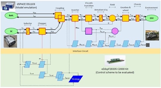
The signal HIL simulation was carried out to demonstrate the real-time ability of the EMSs when they were realized on an onboard ECU. Figure 16 and Figure 17 show the principle and the experimental setup of the signal HIL simulation for the HESS in this work, respectively.
Firstly, the model of the HESS and the traction subsystem was simulated in the dSPACE DS1103 control station. The modeling and control of the EV traction system were also implemented in this rapid prototyping board because the main purpose of this experiment was to validate the real-time operation of the proposed EMS. Secondly, the eZdspF28335 C2000 ECU kit was used to execute the controllers and the EMS of the HESS. The emulated ECU (dSPACE DS1103) and control ECU (C2000 kit) communicated with each other through an interface circuit, which performed the same signal measurements as the real-world process. The interface circuit consisted of the DAC to provide analog output signals for four measured variables (, , , and ) as the voltage and current sensors, the ADC to help the control ECU collect these measurement data, and the CAN bus to transmit the modulation function m.
4.3.2. Results and Discussion
The offline simulation indicated that the energy-based strategy showed the best performance, especially in fluctuating driving conditions. Thus, the evaluated scenario for the signal HIL simulation of the studied system was the energy-based algorithm in another fluctuating driving cycle: the Worldwide harmonized Light vehicles Test Cycles (WLTC) Class 2. This cycle represents driving patterns of vehicles in India, Japan, and Europe and is currently used to evaluate emission performance for newly sold cars. The SC was also fully charged at the initial stage as this is the most common operating condition of EVs for their first run in the morning.
The response velocity of the EV traction system is shown in Figure 18. It can be pointed out that matched the reference and offline simulation velocity values perfectly. The experimental results of the signal HIL system are reported in Figure 19 and Figure 20. It can be seen that the real-time HESS currents and matched the simulation ones and well. The SC voltage was also the same as with only a small ripple.
However, there were some slight deviations between the experimental results and offline simulation results due to noises in the communication process between the two ECU kits, which are illustrated in Figure 19b and Figure 20b. In conclusion, the signal HIL experimental validation results demonstrated that the proposed EMS could be feasibly and effectively realized on an onboard ECU. The computation time of the EMS in the ECU was very fast, which was within the sampling rate of 0.5 ms. The behaviors of the offline simulation system were accurately verified by the real-time platform system.
5. Conclusions
This paper proposed three simple, but effective adaptive filter-based strategies for the power allocation of a battery/SC EV, which relied on the SC stored energy, SOC, and voltage. We aimed to show the feasibility in a real-world implementation because the algorithms can be performed with only two measured variables and require less computational effort. Besides, the complex system modeling and control design became straightforward thanks to EMR and the inversion-based control principle. Furthermore, the system control and EMS can be transferred from the simulation development environment to a real common microcontroller kit, eZdspF28335, quickly and conveniently.
These proposed methods were compared to each other before they were analyzed together with a pure battery car and a conventional filtering method under the same working conditions to find the most effective solution. Simulation results showed that the HESS and EMS had significant roles in protecting the battery under fluctuating driving conditions such as the urban profile. In the UADC, the rms current of the battery of the HESS with the energy-based strategy was only about one-third of that of the battery-only vehicle. Additionally, the standard deviation value of the battery current using this algorithm was even reduced by up to 83% compared to the battery EV. Finally, the simplicity and effectiveness of the proposed strategies led to the perfect onboard real-time implementation with only a 0.5 ms computation time of the ECU. The real-time signal HIL validation verified the capability of the proposed strategies to be employed in real-world vehicular applications.
Author Contributions
Conceptualization and methodology, B.-H.N.; software, H.-L.T.N.; validation, T.V.-D., B.-H.N., and J.P.F.T.; formal analysis, H.-L.T.N., T.V.-D., B.-H.N., and J.P.F.T.; investigation, H.-L.T.N. and B.-H.N.; resources, T.V.-D., B.-H.N., and J.P.F.T.; data curation, H.-L.T.N.; writing—original draft preparation, H.-L.T.N.; writing—review and editing, T.V.-D., B.-H.N., and J.P.F.T.; visualization, H.-L.T.N.; supervision, T.V.-D., B.-H.N., and J.P.F.T.; project administration, B.-H.N. and J.P.F.T.; funding acquisition, T.V.-D. and J.P.F.T. All authors read and agreed to the published version of the manuscript.
Funding
Hoai-Linh T. Nguyen was funded by Vingroup Joint Stock Company and supported by the Domestic Master/PhD Scholarship Programme of Vingroup Innovation Foundation (VINIF), Vingroup Big Data Institute (VINBIGDATA), Code VINIF.2020.ThS.47. This work was supported in part by Grant 950-230672 from Canada Research Chairs Program, in part by Grant 2019-NC-252886 from Fonds de recherche du Québec – Nature et Technologies, in part by FCT (Portuguese Foundation for Science and Technology) Project UIDB/00308/2020, and by the European Regional Development Fund through the COMPETE 2020 Program within Project MAnAGER (POCI-01-0145-FEDER-028040).
Institutional Review Board Statement
Not applicable.
Informed Consent Statement
Not applicable.
Acknowledgments
The authors would like to thank Minh Truong Doan from CTI Lab. for EVs for his assistance to Hoai-Linh T. Nguyen in carrying out the signal HIL experiment.
Conflicts of Interest
The authors declare no conflict of interest.
Abbreviations
The following abbreviations are used in this manuscript:
| HESS | Hybrid energy storage system |
| EMS | Energy management strategy |
| SC | Supercapacitor |
| LQR | Linear quadratic regulation |
| HESS | Hybrid energy storage system |
| EMS | Energy management strategy |
| SC | Supercapacitor |
| HESS | Hybrid energy storage system |
| EMS | Energy management strategy |
| SC | Supercapacitor |
| LQR | Linear quadratic regulation |
| PMP | Pontryagin’s minimum principle |
| EMR | Energetic macroscopic representation |
| IPMSM | Interior permanent magnet synchronous motor |
| SOC | State-of-charge |
| AFS | Adaptive filtering strategy |
| NEDC | New European Driving Cycle |
| AUDC | Artemis Urban Driving Cycle |
| WLTC | Worldwide harmonized Light vehicles Test Cycles |
| ECU | Electronic control unit |
Appendix A
Figure A1.
EMR elements.

References
- Barré, A.; Deguilhem, B.; Grolleau, S.; Gérard, M.; Suard, F.; Riu, D. A review on lithium-ion battery ageing mechanisms and estimations for automotive applications. J. Power Sources 2013, 241, 680–689. [Google Scholar] [CrossRef] [Green Version]
- Ma, S.; Jiang, M.; Tao, P.; Song, C.; Wu, J.; Wang, J.; Deng, T.; Shang, W. Temperature effect and thermal impact in lithium-ion batteries: A review. Prog. Nat. Sci. Mater. Int. 2018, 28, 653–666. [Google Scholar] [CrossRef]
- Han, X.; Lu, L.; Zheng, Y.; Feng, X.; Li, Z.; Jianqiu, L.; Ouyang, M. A review on the key issues of the lithium ion battery degradation among the whole life cycle. eTransportation 2019, 1, 100005. [Google Scholar] [CrossRef]
- Tran, D.D.; Vafaeipour, M.; El Baghdadi, M.; Barrero, R.; Van Mierlo, J.; Hegazy, O. Thorough state-of-the-art analysis of electric and hybrid vehicle powertrains: Topologies and integrated energy management strategies. Renew. Sustain. Energy Rev. 2020, 119, 109596. [Google Scholar] [CrossRef]
- Schaltz, E.; Khaligh, A.; Rasmussen, P.O. Influence of Battery/Ultracapacitor Energy-Storage Sizing on Battery Lifetime in a Fuel Cell Hybrid Electric Vehicle. IEEE Trans. Veh. Technol. 2009, 58, 3882–3891. [Google Scholar] [CrossRef]
- Song, Z.; Hofmann, H.; Li, J.; Hou, J.; Han, X.; Ouyang, M. Energy management strategies comparison for electric vehicles with hybrid energy storage system. Appl. Energy 2014, 134, 321–331. [Google Scholar] [CrossRef]
- Trovão, J.P.; Silva, M.A.; Antunes, C.H.; Dubois, M.R. Stability enhancement of the motor drive DC input voltage of an electric vehicle using onboard hybrid energy storage systems. Appl. Energy 2017, 205, 244–259. [Google Scholar] [CrossRef]
- Nguyen, B.H.; German, R.; Trovao, J.P.F.; Bouscayrol, A. Real-time energy management of battery/supercapacitor electric vehicles based on an adaptation of pontryagin’s minimum principle. IEEE Trans. Veh. Technol. 2019, 68, 203–212. [Google Scholar] [CrossRef] [Green Version]
- Vinot, E.; Trigui, R. Optimal energy management of HEVs with hybrid storage system. Energy Convers. Manag. 2013, 76, 437–452. [Google Scholar] [CrossRef] [Green Version]
- Hussain, S.; Ali, M.U.; Nengroo, S.H.; Khan, I.; Ishfaq, M.; Kim, H.J. Semiactive hybrid energy management system: A solution for electric wheelchairs. Electronics 2019, 8, 345. [Google Scholar] [CrossRef] [Green Version]
- Salmasi, F.R. Control Strategies for Hybrid Electric Vehicles: Evolution, Classification, Comparison, and Future Trends. IEEE Trans. Veh. Technol. 2007, 56, 2393–2404. [Google Scholar] [CrossRef]
- Peng, J.; Wang, R.; Liao, H.; Zhou, Y.; Li, H.; Wu, Y.; Huang, Z. A Real-Time Layer-Adaptive Wavelet Transform Energy Distribution Strategy in a Hybrid Energy Storage System of EVs. Energies 2019, 12, 440. [Google Scholar] [CrossRef] [Green Version]
- Thounthong, P.; Rael, S. The benefits of hybridization. IEEE Ind. Electron. Mag. 2009, 3, 25–37. [Google Scholar] [CrossRef]
- Wang, L.; Collins, E.G.; Li, H. Optimal Design and Real-Time Control for Energy Management in Electric Vehicles. IEEE Trans. Veh. Technol. 2011, 60, 1419–1429. [Google Scholar] [CrossRef]
- Rajabzadeh, M.; Bathaee, S.M.T.; Aliakbar Golkar, M. Dynamic modeling and nonlinear control of fuel cell vehicles with different hybrid power sources. Int. J. Hydrog. Energy 2016, 41, 3185–3198. [Google Scholar] [CrossRef]
- Yu, Y.B.; Liu, X.; Min, H.; Sun, H.; Xu, L. A novel fuzzy-logic based control strategy for a semi-active battery/super-capacitor hybrid energy storage system in vehicular applications. J. Intell. Fuzzy Syst. 2015, 29, 2575–2584. [Google Scholar] [CrossRef] [Green Version]
- Wang, Y.; Wang, W.; Zhao, Y.; Yang, L.; Chen, W. A Fuzzy-Logic Power Management Strategy Based on Markov Random Prediction for Hybrid Energy Storage Systems. Energies 2016, 9, 25. [Google Scholar] [CrossRef]
- Xiong, R.; Cao, J.; Yu, Q. Reinforcement learning-based real-time power management for hybrid energy storage system in the plug-in hybrid electric vehicle. Appl. Energy 2017, 211, 538–548. [Google Scholar] [CrossRef]
- Hu, Y.; Li, W.; Xu, K.; Zahid, T.; Qin, F.; Li, C. Energy management strategy for a hybrid electric vehicle based on deep reinforcement learning. Appl. Sci. 2018, 8, 187. [Google Scholar] [CrossRef] [Green Version]
- Adnane, M.; Nguyễn, B.H.; Khoumsi, A.; Trovão, J.P.F. Driving Mode Predictor-based Real-Time Energy Management for Dual-Source Electric Vehicle. IEEE Trans. Transp. Electrif. 2021, 1. [Google Scholar] [CrossRef]
- Trovão, J.P.; Pereirinha, P.G.; Jorge, H.M.; Antunes, C.H. A multi-level energy management system for multi-source electric vehicles—An integrated rule-based meta-heuristic approach. Appl. Energy 2013, 105, 304–318. [Google Scholar] [CrossRef]
- Yao, L.; Damiran, Z.; Lim, W.H. Optimal charging and discharging scheduling for electric vehicles in a parking station with photovoltaic system and energy storage system. Energies 2017, 10, 550. [Google Scholar] [CrossRef]
- Sundstrom, O.; Guzzella, L. A generic dynamic programming Matlab function. In Proceedings of the 2009 IEEE Control Applications, (CCA) & Intelligent Control, (ISIC), St. Petersburg, Russia, 8–10 July 2009; pp. 1625–1630. [Google Scholar] [CrossRef]
- Nguyễn, B.H.; Vo-Duy, T.; Henggeler Antunes, C.; Trovão, J.P.F. Multi-objective benchmark for energy management of dual-source electric vehicles: An optimal control approach. Energy 2021, 223, 119857. [Google Scholar] [CrossRef]
- Nguyễn, B.H.; Vo-Duy, T.; Ta, M.C.; Trovão, J.P.F. Optimal Energy Management of Hybrid Storage Systems Using an Alternative Approach of Pontryagin’s Minimum Principle. IEEE Trans. Transp. Electrif. 2021, 1. [Google Scholar] [CrossRef]
- Nguyen, B.H.; Trovão, J.P.F.; German, R.; Bouscayrol, A. Real-time energy management of parallel hybrid electric vehicles using linear quadratic regulation. Energies 2020, 13, 5538. [Google Scholar] [CrossRef]
- Golchoubian, P.; Azad, N.L. Real-Time Nonlinear Model Predictive Control of a Battery–Supercapacitor Hybrid Energy Storage System in Electric Vehicles. IEEE Trans. Veh. Technol. 2017, 66, 9678–9688. [Google Scholar] [CrossRef]
- Zhang, Y.; Liu, H.; Zhang, Z.; Luo, Y.; Guo, Q.; Liao, S. Cloud computing-based real-time global optimization of battery aging and energy consumption for plug-in hybrid electric vehicles. J. Power Sources 2020, 479, 229069. [Google Scholar] [CrossRef]
- Trovão, J.P.; Silva, M.A.; Dubois, M.R. Coupled energy management algorithm for MESS in urban EV. IET Electr. Syst. Transp. 2017, 7, 125–134. [Google Scholar] [CrossRef]
- Asensio, E.M.; Magallán, G.A.; De Angelo, C.H.; Serra, F.M. Energy Management on Battery/Ultracapacitor Hybrid Energy Storage System based on Adjustable Bandwidth Filter and Sliding-mode Control. J. Energy Storage 2020, 30, 101569. [Google Scholar] [CrossRef]
- Allègre, A.L.; Bouscayrol, A.; Trigui, R. Flexible real-time control of a hybrid energy storage system for electric vehicles. IET Electr. Syst. Transp. 2013, 3, 79–85. [Google Scholar] [CrossRef]
- Castaings, A.; Lhomme, W.; Trigui, R.; Bouscayrol, A. Comparison of energy management strategies of a battery/supercapacitors system for electric vehicle under real-time constraints. Appl. Energy 2016, 163, 190–200. [Google Scholar] [CrossRef]
- Snoussi, J.; Ben Elghali, S.; Benbouzid, M.; Mimouni, M.F. Auto-adaptive filtering-based energy management strategy for fuel cell hybrid electric vehicles. Energies 2018, 11, 2118. [Google Scholar] [CrossRef] [Green Version]
- Hussain, S.; Ali, M.U.; Park, G.s.; Nengroo, S.H.; Khan, M.A.; Kim, H.j. A Real-Time Bi-Adaptive Controller-Based Energy Hybrid Electric Vehicles. Energies 2019, 12, 4662. [Google Scholar] [CrossRef] [Green Version]
- Florescu, A.; Bacha, S.; Munteanu, I.; Bratcu, A.I.; Rumeau, A. Adaptive frequency-separation-based energy management system for electric vehicles. J. Power Sources 2015, 280, 410–421. [Google Scholar] [CrossRef]
- Tani, A.; Camara, M.B.; Dakyo, B. Energy Management Based on Frequency Approach for Hybrid Electric Vehicle Applications: Fuel-Cell/Lithium-Battery and Ultracapacitors. IEEE Trans. Veh. Technol. 2012, 61, 3375–3386. [Google Scholar] [CrossRef]
- Vo-Duy, T.; Ta, M.C.; Nguyễn, B.H.; Trovão, J.P.F. Experimental Platform for Evaluation of On-Board Real-Time Motion Controllers for Electric Vehicles. Energies 2020, 13, 6448. [Google Scholar] [CrossRef]
- Bouscayrol, A. Graphic Formalisms for the Control of Multi-Physical Energetic Systems: COG and EMR. In Systemic Design Methodologies for Electrical Energy Systems; Wiley: Hoboken, NJ, USA, 2013; pp. 89–124. [Google Scholar] [CrossRef]
- Nguyen, B.; Trovao, J.P.F.; German, R.; Bouscayrol, A. Impact of Supercapacitors on Fuel Consumption and Battery Current of a Parallel Hybrid Truck. In Proceedings of the 2019 IEEE Vehicle Power and Propulsion Conference (VPPC), Hanoi, Vietnam, 14–17 October 2019; pp. 1–6. [Google Scholar] [CrossRef]
- Dépature, C.; Lhomme, W.; Sicard, P.; Bouscayrol, A.; Boulon, L. Real-Time Backstepping Control for Fuel Cell Vehicle Using Supercapacitors. IEEE Trans. Veh. Technol. 2018, 67, 306–314. [Google Scholar] [CrossRef]
- Vo-Duy, T.; Nguyen, B.H.; Ta, M.C.; Trovão, J.P.; Nguyen, N. Different Voltage and Current Control Schemes for Multi-pack Battery of Electric Scooters. In Proceedings of the 2020 IEEE Vehicle Power and Propulsion Conference (VPPC), Gijon, Spain, 18 November–16 December 2020; pp. 1–5. [Google Scholar] [CrossRef]
- Nam, K. AC Motor Control and Electrical Vehicle Applications, 2nd ed.; CRC Press: Boca Raton, FL, USA, 2018. [Google Scholar] [CrossRef]
- Lee, S.C.; Jung, W.Y. Analogical understanding of the Ragone plot and a new categorization of energy devices. Energy Procedia 2016, 88, 526–530. [Google Scholar] [CrossRef] [Green Version]
- Trovão, J.P.F.; Roux, M.; Ménard, É.; Dubois, M.R. Energy- and Power-Split Management of Dual Energy Storage System for a Three-Wheel Electric Vehicle. IEEE Trans. Veh. Technol. 2017, 66, 5540–5550. [Google Scholar] [CrossRef]
- Nguyen, C.T.P.; Nguyễn, B.H.; Trovão, J.P.F.; Ta, M.C. Effect of battery voltage variation on electric vehicle performance driven by induction machine with optimal flux-weakening strategy. IET Electr. Syst. Transp. 2020, 10, 351–359. [Google Scholar] [CrossRef]
Figure 1.
A semi-active battery /SC EV system configuration.

Figure 2.
EMR and inversion-based control of the i-MiEV car traction system.

Figure 3.
EMR and inversion-based control of the HESS for the EV.

Figure 4.
Adaptive low-pass filter transformation.

Figure 5.
Supercapacitor recharge control block.

Figure 6.
Limitation transition block.

Figure 7.
Implementation of the strategy block.

Figure 8.
Experimental Mitsubishi i-MiEV.

Figure 9.
Experimental supercapacitor NESSCAP EMHSR-0062C0-125R0SR2.

Figure 10.
Velocity of the studied driving cycles: (a) NEDC; (b) Artemis urban.

Figure 11.
Traction currents in the studied driving cycles: (a) NEDC; (b) Artemis urban.

Figure 12.
Battery currents with the EMS under two driving cycles: (a) Battery currents with the NEDC; (b) Zoom shape of battery currents with the NEDC; (c) Battery currents with the AUDC; (d) Zoom shape of battery currents with the AUDC.
Figure 12.
Battery currents with the EMS under two driving cycles: (a) Battery currents with the NEDC; (b) Zoom shape of battery currents with the NEDC; (c) Battery currents with the AUDC; (d) Zoom shape of battery currents with the AUDC.

Figure 13.
Performance of the studied EMS for the battery/SC EV from the simulations: (a) Root mean squared currents of the battery; (b) Standard deviation of the battery currents.
Figure 13.
Performance of the studied EMS for the battery/SC EV from the simulations: (a) Root mean squared currents of the battery; (b) Standard deviation of the battery currents.

Figure 14.
SC voltages with the studied strategies in the NEDC: (a) SOC-based strategy; (b) Energy-based strategy; (c) Voltage-based strategy; (d) Conventional filtering strategy.
Figure 14.
SC voltages with the studied strategies in the NEDC: (a) SOC-based strategy; (b) Energy-based strategy; (c) Voltage-based strategy; (d) Conventional filtering strategy.

Figure 15.
SC voltages with the studied strategies in the UADC: (a) SOC-based strategy; (b) Energy-based strategy; (c) Voltage-based strategy; (d) Conventional filtering strategy.
Figure 15.
SC voltages with the studied strategies in the UADC: (a) SOC-based strategy; (b) Energy-based strategy; (c) Voltage-based strategy; (d) Conventional filtering strategy.

Figure 16.
Signal HIL system for real-time experimental validation.

Figure 17.
Experimental test bench.

Figure 18.
Velocity of the EV in WLTC Class 2 in the signal HIL experiment: (a) Full driving cycle; (b) Zoom shape.
Figure 18.
Velocity of the EV in WLTC Class 2 in the signal HIL experiment: (a) Full driving cycle; (b) Zoom shape.

Figure 19.
Experimental results of the HESS currents (energy-based strategy): (a) Full driving cycle; (b) Zoom shape.
Figure 19.
Experimental results of the HESS currents (energy-based strategy): (a) Full driving cycle; (b) Zoom shape.

Figure 20.
Experimental results of the SC voltage (energy-based strategy): (a) Full driving cycle; (b) Zoom shape.
Figure 20.
Experimental results of the SC voltage (energy-based strategy): (a) Full driving cycle; (b) Zoom shape.


Table 1.
Equations for the control scheme of the powertrain system.
| Traction System |
|---|
| HESS |
Table 2.
System parameters.
| Specifications | Values | |
|---|---|---|
| EV (i-MiEV) | ||
| Vehicle total weight | 1250 kg | |
| Gear box ratio | 7.065 | |
| Wheel radius | 0.2844 m | |
| Aerodynamic standard | 0.8295 m2 | |
| Rolling friction coefficient | 0.02 | |
| Air density (at 20 ) | 1.25 kg/m3 | |
| IPMSM | ||
| Maximum power | 49 kW | |
| The number of polar pairs | 4 | |
| Pole flux | 0.06 Wb | |
| Stator inductance | 140 µH | |
| 210 µH | ||
| Windings’ resistance | 12 m | |
| Battery module (LEV50 Li-ion) | ||
| Cell storage capacity | 50 Ah | |
| Cell OCV | 3.7 V | |
| Cell OCV (at 20% SOC) | 3.06 V | |
| Cell resistance | 1.7 m | |
| Number of cells in series | 88 | |
| Number of cells in parallel | 1 | |
| SC module (NESSCAP EMHSR-0062C0-125R0SR2) | ||
| SC module nominal voltage | 125 V | |
| SC module nominal capacitance | 62 F | |
| SC module internal resistance | 10 m | |
Publisher’s Note: MDPI stays neutral with regard to jurisdictional claims in published maps and institutional affiliations. |
© 2021 by the authors. Licensee MDPI, Basel, Switzerland. This article is an open access article distributed under the terms and conditions of the Creative Commons Attribution (CC BY) license (https://creativecommons.org/licenses/by/4.0/).
Share and Cite
MDPI and ACS Style
Nguyen, H.-L.T.; Nguyễn, B.-H.; Vo-Duy, T.; Trovão, J.P.F. A Comparative Study of Adaptive Filtering Strategies for Hybrid Energy Storage Systems in Electric Vehicles. Energies 2021, 14, 3373. https://doi.org/10.3390/en14123373
AMA Style
Nguyen H-LT, Nguyễn B-H, Vo-Duy T, Trovão JPF. A Comparative Study of Adaptive Filtering Strategies for Hybrid Energy Storage Systems in Electric Vehicles. Energies. 2021; 14(12):3373. https://doi.org/10.3390/en14123373
Chicago/Turabian StyleNguyen, Hoai-Linh T., Bảo-Huy Nguyễn, Thanh Vo-Duy, and João Pedro F. Trovão. 2021. "A Comparative Study of Adaptive Filtering Strategies for Hybrid Energy Storage Systems in Electric Vehicles" Energies 14, no. 12: 3373. https://doi.org/10.3390/en14123373
Note that from the first issue of 2016, this journal uses article numbers instead of page numbers. See further details here.