
Optimization of a Small Wind Power Plant for Annual Wind Speed Distribution


1
Division of Drive Automation and Robotics, Faculty of Electrical Engineering, Automatic Control and Informatics, Opole University of Technology, 45-758 Opole, Poland
2
Institute of Electrical Engineering and Electronics, Faculty of Control, Robotics and Electrical Engineering, Poznan University of Technology, Piotrowo 3A, 60-965 Poznan, Poland
*
Authors to whom correspondence should be addressed.
Energies 2021, 14(6), 1587; https://doi.org/10.3390/en14061587
Submission received: 13 February 2021
/
Revised: 6 March 2021
/
Accepted: 9 March 2021
/
Published: 12 March 2021
(This article belongs to the Special Issue Numerical Computations in Modeling, Analysis and Optimization of Energy Conversion in Electromagnetic Devices, Electrical Machines and Drives)
Abstract
:This article presents a method to adjust the elements of a small wind power plant to the wind speed characterized by the highest annual level of energy. Tests were carried out on the basis of annual wind distributions at three locations. The standard range of wind speeds was reduced to that resulting from the annual wind speed distributions in these locations. The construction of the generators and the method of their excitation were adapted to the characteristics of the turbines. The results obtained for the designed power plants were compared with those obtained for a power plant with a commercial turbine adapted to a wind speed of 10 mps. The generator structure and control method were optimized using a genetic algorithm in the MATLAB program (Mathworks, Natick, MA, USA); magnetostatic calculations were carried out using the FEMM program; the simulations were conducted using a proprietary simulation program. The simulation results were verified by measurement for a switched reluctance machine of the same voltage, power, and design. Finally, the yields of the designed generators in various locations were determined.
1. Introduction
Wind farms account for a significant share of the world’s electricity production. Development in a given location is determined mainly by wind conditions [1,2,3,4,5,6,7,8,9,10]. Most wind farms are built in coastal areas and on continental shelves [10,11,12,13,14,15,16,17,18]. Inland, wind conditions, being determined by various topographical and other factors, vary greatly [1,11,19,20,21,22]. Therefore, the construction of wind farms in such locations should be preceded by studies of annual wind distribution in these locations.
Most wind farms work with the local power grid [8,18,23,24,25,26,27,28,29]. However, in places far from a power grid, electricity can be provided only by means of renewable energy sources with their own energy storage systems, most often accumulators. In this case, low-voltage wind generators and photovoltaic panels are most often used [9,29,30,31,32,33,34,35,36].
One type of generator used in wind turbines is a switched reluctance generator (SRG) [37]. Generators of this type are used both in large systems connected to the power grid and in microinstallations [38,39,40,41].
SRG generators can be built in the form of a typical single magnetic circuit or in the form of segments constituting separate magnetic circuits closed by rotor teeth [42].
The stator windings of the SRG are excited by an electronic power system. This makes it possible to adjust the excitation conditions (switch-on angle αon and switch-off angle αoff or phase supply angular range Δα) to the operating point, that is, to rotational speed and torque [43,44,45,46,47,48,49]. An additional advantage of this solution is that the winding, in tandem with the electronic excitation system, forms a step-up converter. This makes it possible to obtain the rated voltage value even at low rotational speeds [50,51].
Low-power generators operating off-grid can be found in many places today. In combination with solar panels, they are often used to power road signals and pedestrian crossings outside built-up areas. They are also often used, for example, to supply water-level measurement stations in rivers [52,53].
Increasingly, small generators are also being installed on yachts, at camping sites, and in hard-to-reach tourist spots. Due to their relatively modest dimensions, they can be located in tourist areas without significantly affecting the landscape. However, they are often installed in places characterized by unfavorable weather conditions [54]. In such cases, typical commercially available turbine solutions do not provide sufficient capacity, as they are designed to operate at higher wind speeds.
In order to use low-speed winds to produce electricity, an individual approach to wind turbine design is required, taking into account the annual distribution of wind speed at the site of its construction.
The optimal design of the magnetic circuit and windings and the optimal excitation method of the SRG enable the generation of electricity over a wide range of rotational speeds. However, the wind energy must be supplied to the generator by a turbine with appropriate parameters, i.e., size and characteristics [21]. Commercial turbines are most often projected to operate at wind speeds of 10–12 mps. At lower speeds their actual power is much lower than their declared rated power. As a result, their characteristics enable operation at wind speeds up to 25 mps. The presented solution assumes adjustment of the size of the turbine to the annual wind speed distribution at the location of its installation. It was assumed that the turbine would attain the rated power at the wind speed with the highest annual level of energy. The size of the turbine must be adapted to this speed in order to attain the rated power of the generator. The turbine power should then remain constant up to the cutoff speed.
The maximum value of wind speed included in the annual distribution in the predicted location was assumed as the cutoff speed. However, this is due to the fact that, in the event of winds with a speed greater than that resulting from the annual wind speed distribution, the turbine must be turned off.
Much work involves optimizing the performance of wind farms. They most often contain information related to the construction of turbines, generators, and control systems. In [55,56] the influence of turbine construction on the annual energy production was presented. Among others, turbines with different number of blades, their shape and position were studied. The article [57] also presents the optimization of the rotor blades, but in order to increase the aerodynamic efficiency in the low wind speed range. In article [58] the problem of minimizing a mass of the turbine in order to accelerate its start-up is discussed.
An example of the application of the genetic algorithm to minimize the return on investment costs of building a wind turbine is presented in [59], whereas in [60] an evolutionary strategy was used in order to obtain a higher output power and improve the generator power factor. An example of the optimization of the SRG generator operating at variable speed in terms of efficiency is presented in [61]. In this work, optimization was performed by adjusting the DC voltage and excitation angles values. Optimization of the turbine operation in the low speed range is also discussed in [62]. The purpose of this work was to optimize the power–wind speed curve of a wind turbine.
The given examples show that due to the various components of a wind turbine, each of which has an impact on its operation, it is advisable to optimize all of them in order to achieve high efficiency.
The study included the adjustment of the turbine characteristics to the annual wind distribution, optimization of the SRG generator construction, and method of its excitation. The calculations were made on the basis of annual wind speed distributions in three locations that differ greatly in terms of wind conditions: at the seaside, in the lowlands, and in the foothills.
The main goal of the study is to increase the annual energy production in small wind plants operating in locations with poor wind conditions by adjusting its elements to the annual wind distribution. The presented approach is based on the distribution of expected annual energy production by the winds of different speeds.
The basic issues presented in the work are the selection of a turbine to the annual wind distribution, the adjustment of the generator structure to the characteristics of the turbine, the selection of winding parameters, and the determination of optimal excitation conditions. An additional aim is to identify which of these elements have the greatest impact on the annual energy production. In the second part, the wind speeds providing the highest level of energy per year were determined. On this basis, the size of the wind turbines and the distribution of annual energy as a function of wind speed were estimated. The third part discusses the mathematical model of the generator implemented in the simulation program and verification of its measured results. The fourth part presents the algorithm and criteria for optimization of the generator structure and excitation parameters depending on the location of the power plant. The fifth part presents the optimization results and the characteristics obtained for optimized power plants, and their comparison with the parameters of typical commercial solutions. The sixth part discusses the obtained results.
2. Determination of Turbine Parameters
Typical small wind power plants are designed for rated wind speeds from 10 to 12 mps. In regions with poor wind conditions, these plants do not yield annual energy production sufficient to guarantee the profitability of the investment. In order to increase the quantity of produced energy, it was assumed that a generator reaches its rated power at the wind speed at which the highest level of energy is obtained annually. The characteristics of the turbine should be adjusted so that the power does not increase above this speed. In accordance with such assumptions, the expected dependence of the generator torque on the rotational speed was determined.
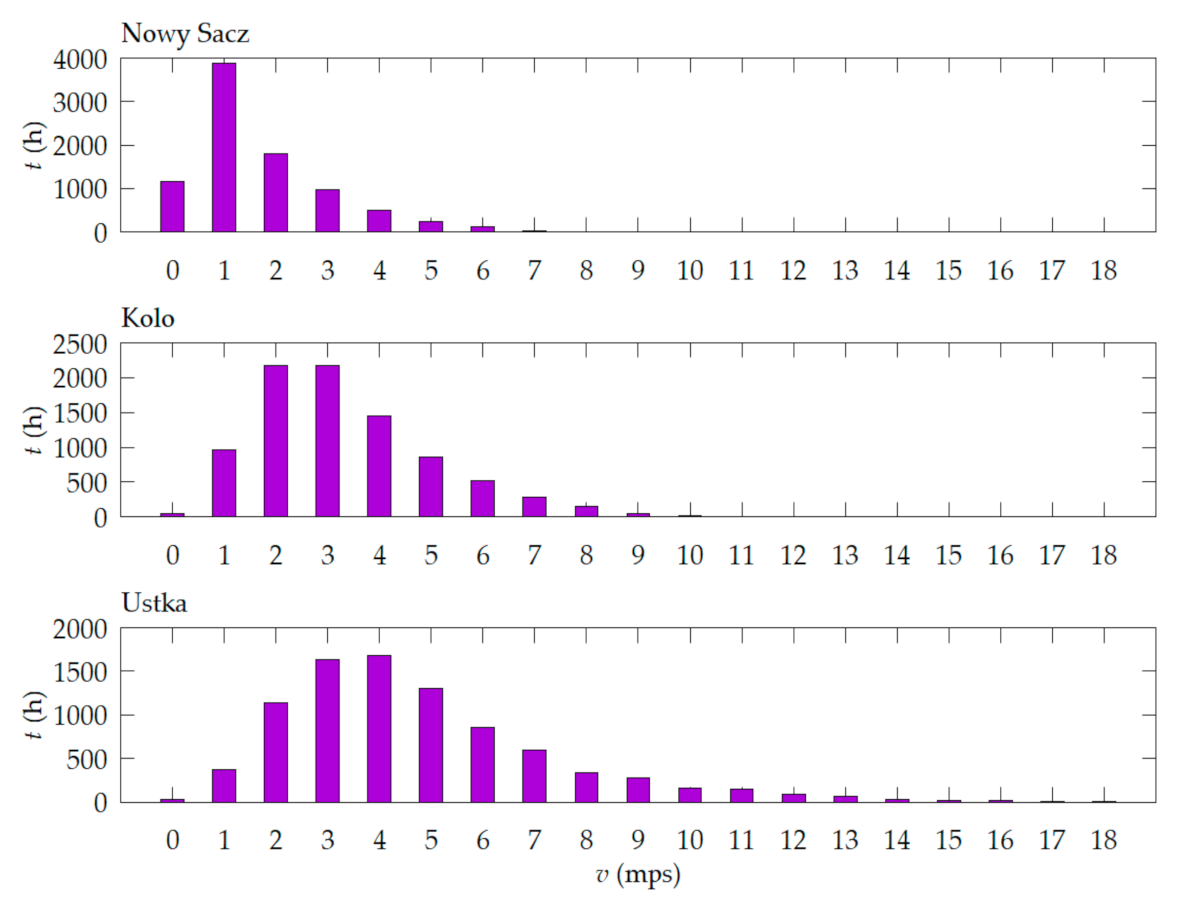
The input data for the calculations consisted of the annual wind speed distributions obtained via measurement in three locations. The first location was a foothill area with poor wind conditions (Nowy Sacz, Poland). The second was a lowland area, located several hundred kilometers from the sea, with average wind conditions (Kolo, Poland). The third covered a seaside region with relatively good wind conditions (Ustka, Poland). Annual wind speed distributions in these locations are shown in Figure 1. Measurements were made at a height of 10 m.
The maximum speeds in the diagrams of annual wind distribution for these locations were adopted during the design process as cutoff speeds: 10 mps for Nowy Sacz, 11 mps for Kolo, 18 mps for Ustka. Typically, winds with speeds up to 25 mps are taken into account, but in these locations, winds with speeds higher than those shown in Figure 1 do not contribute significantly to annual energy production. The adopted cutoff speeds were taken into account in the course of the gear calculations so that the maximum speed of the generator was 50 rps in each case. For the calculations, it was assumed that the transmission losses amounted to 3% (gear efficiency ηg = 97%). At the same time, based on the results of previous measurements and calculations, the estimated value of the generator’s efficiency at the rated point was also assumed to be ηG = 85%. In this way, the power P1 transmitted from the turbine to the generator was calculated in order to obtain the plant output power P2 = 1 kW with (1).
where:
- ηg—mechanical gear efficiency;
- ηG—generator efficiency.
According to (1), the power output from the turbine at the rated point should be 1213 W. Assuming that wind power is proportional to its speed to the third power, the relative wind power was calculated for each speed (2, 3). Then, based on the distribution of wind speed and power, the relative distribution of energy delivered annually by wind for each speed was calculated separately as a percentage of the expected annual energy production:
where
- pv—power transmitted by the wind at speed v, expressed as a relative percentage to attend the annual wind speed distribution in a particular location;
- Pv—the power of the wind speed v per unit of area;
- ΣPi—total wind power with speeds included in the annual distribution per unit of area;
- Nv—number of hours in the year of wind speed v;
- ev—percentage of energy supplied by wind speed v in the total energy supplied by winds with speeds included in the annual distribution.
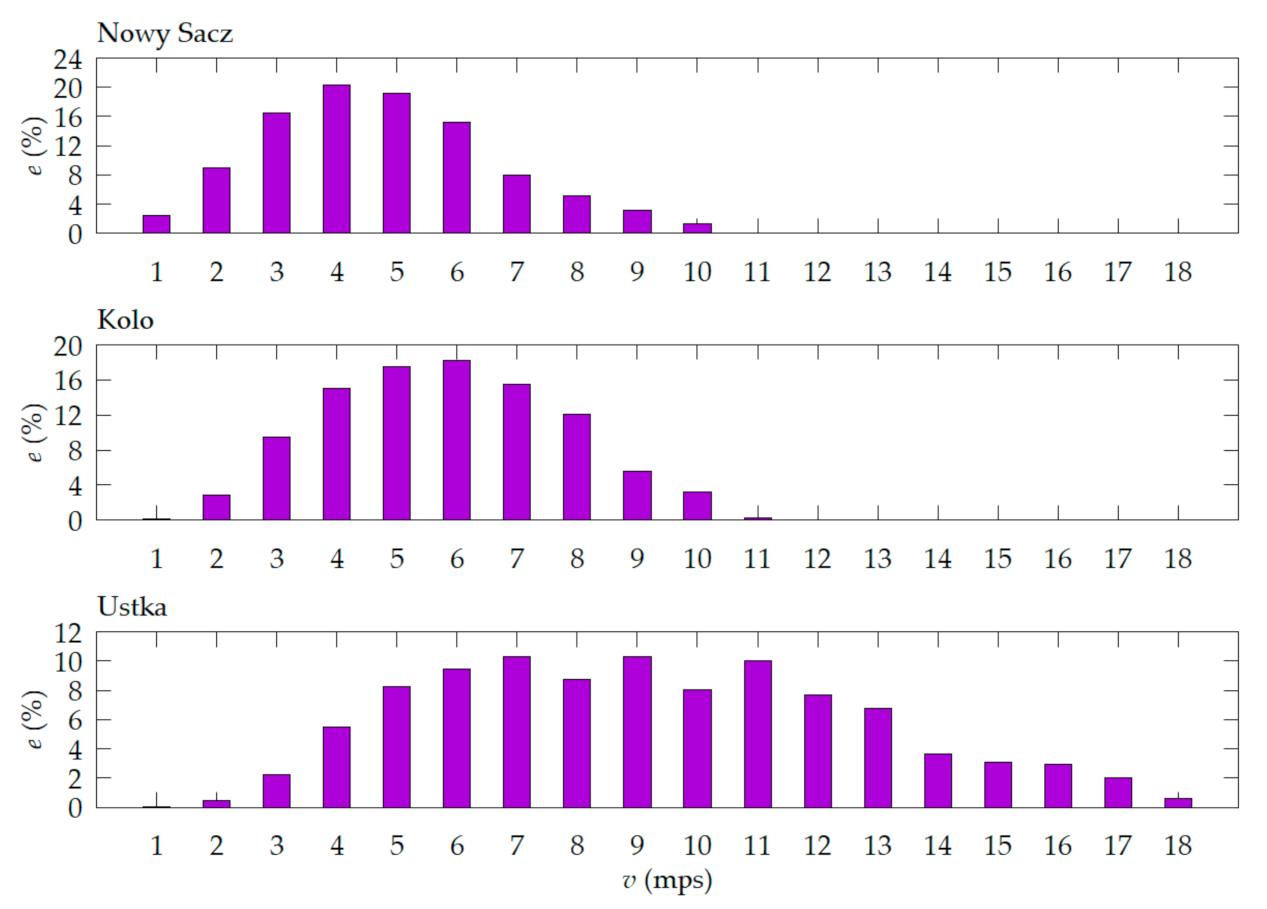
In this way, the speeds v(emax) at which wind supplies the most energy annually in the discussed locations were determined (Figure 2). For the tested locations, these speeds were 5 mps (because for 4 mps the radius of the turbine would be too large for the determined height of 10 m) for Nowy Sacz, 6 mps for Kolo, and 7 mps for Ustka. Then, for the determined wind speeds, the corresponding rotational speeds of the turbines at which they obtained the rated power were calculated.
By transforming the dependence of turbine output power (4), the turbine radius enabling attainment of the rated generator power (5) was determined:
where
- S = πr2—turbine working surface;
- R—turbine radius;
- P—turbine output power;
- Cp (λ) = 0.4 power coefficient for a three-blade turbine;
- Λ—tip-speed ratio;
- ρ = 1.225 kg/m3—air density.
Then, for the turbines calculated on the basis of (5), the power delivered by wind with speeds lower than the rated speed was calculated for each location. For speeds higher than the rated speed, a constant power equal to the rated power was assumed. Determination of this kind of dependence requires the design of a suitable profile for the turbine in order to limit its power within the range of speeds higher than the rated speed. For comparison, these calculations were repeated for generators of 1 kW propelled by a typical turbine adapted to the wind speed of 10 mps, with a radius of 1.26 m.
Taking into account the generator’s resistance to motion, the turbine was assumed to start at the power received from the wind above 3% of nominal output power. For lower powers, the value of produced energy is zero. Then, on the basis of (6), the dependencies of the turbine’s rotational speed n on the wind speed v were determined:
where λ = 7 for a three-blade turbine.
Assuming the same maximum speed of 50 rps for all generators achieved at the maximum speed of the turbine, the mechanical gear ratios for all locations were calculated. The values of rated wind speeds and turbine radius, as well as of speed at rated power and cutoff speed obtained in this way, are summarized in Table 1. The last column shows the mechanical gear ratio. For all locations, the maximum speed of the generator was 50 rps.
Based on the dependencies of the output power on the turbine speed and the gear ratio, the dependencies of the generator torque on the rotational speed were calculated from the following:
where
- K = n2/n1—ratio of mechanical gears;
- n1—turbine speed;
- n2—generator speed.
Based on the estimated dependencies of the generator power on the wind speed and the annual wind speed distributions presented in Figure 1, the predicted annual energy production with the use of such turbines was calculated. These calculations do not take the real efficiency of the generators into account. The torque values determined for the rated and maximum speeds were used in the next stage to design and optimize the generators for wind conditions in each of the tested locations.
The results are presented in Table 2, Table 3 and Table 4. The columns include wind speed v, generator torque Tm, generator mechanical power limited to rated power Pm, generator rotational speed n, and generator output power Pe at a given speed. The last two columns show the estimated value of the expected annual energy Eexp production using a wind turbine designed in accordance with the speed at which it obtains the most energy annually and expected annual energy Eexp_std, using a standard turbine adjusted to a speed of 10 mps. The data in Table 2, Table 3 and Table 4 show that adjusting the parameters of wind turbines to the annual wind distribution in the place of their installation is justified, especially in places with poor wind conditions.
3. Mathematical Model of the Generator
The mathematical model of a switched reluctance generator (8), (9) was formulated using the Lagrange method, which accounts for the dependence of the magnetic flux and electromagnetic torque on the rotor position angle and the value of phase currents, as well as nonlinearity characteristics of the magnetic circuit [63,64,65]. Due to the calculation time, the model ignores the influence of mutual magnetic couplings as well as that of eddy currents and hysteresis of the magnetic circuit:
where
- D—losses factor;
- ik—phase current;
- J—moment of inertia;
- Rk—phase resistance;
- Te—electromagnetic torque;
- Tm—torque of the turbine;
- vk—phase voltage;
- θ—rotor position angle;
- Ψk (θ, ik)—magnetic flux of the phase.
In the mathematical model, the electromagnetic torque Te is equal to the flux derivative with respect to the rotor position angle. The dependencies of the phase currents on the rotor position angle and the magnetic flux, as well as dependencies of the electromagnetic torque on the rotor position angle and the phase currents, were implemented in the simulation model in the form of tables. The instantaneous values of these quantities are interpolated by the third-degree spline functions and extrapolated by the first-degree functions. These dependencies were calculated in the FEMM program. The generator is excited in an electronic asymmetric H-bridge system. Commutator modules were simulated for all phases equally. In simulation program, the commutator has been implemented in such a way that the phase is excited if the actual value of the angular position of the rotor is in the range between the switch-on and switch-off angle. The shift of the angular excitation ranges for the others phases were obtained by adding offset to the angular position of first phase. Rotation angle values have been reduced to the repeatability range. The model takes into account two steady-state operations of this system: excitation (both transistors on) and generation (both transistors off). In the excited state, the phase voltage describes the relationship (10), and in the generation state (11).
where
- VS—supply voltage;
- vT SD—transistor saturation voltage;
- vD AC—diode forward voltage.
The simulation program was developed in C # and enables the calculation of voltages, currents and torque. In order to calculate parameters of the generator in steady-state conditions, the model was adapted to calculations at a given speed. The calculations were carried out while accounting for the repeatability period of the waveforms (with the generator rotational speed). This program is a part of the developed environment dedicated to the optimization of switched reluctance generators (SRGs).
The calculations were carried out for a four-phase generator with eight poles in the stator and six teeth in the rotor. The rated voltage of the generator was 24 V; the rated power was 1 kW. The maximum speed was 3000 rpm.
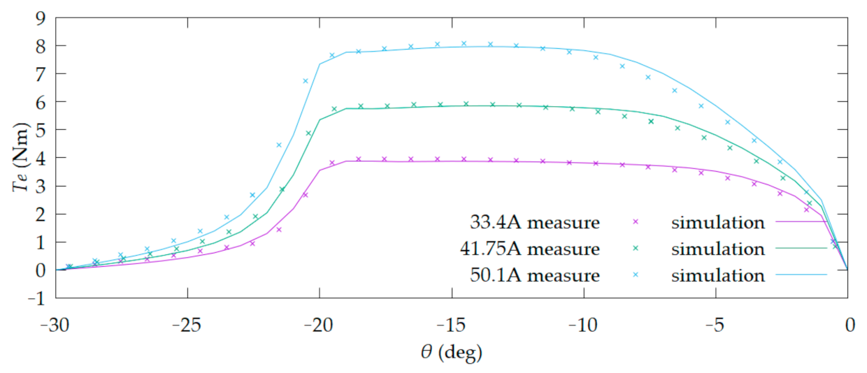
The calculation results in the simulation program were compared with the measurement results obtained for the prototype of the machine in terms of static characteristics and with currents and torque values in steady states. The measured and calculated characteristics of the generator torque are shown in Figure 3.
During the verification of the simulation model, the average values of supply Is av and phase Iph av currents and maximum phase current Iph max obtained for different values of commutation angles at different rotational speeds and torque values were compared. The obtained convergence of results is sufficient to conduct further research based on the simulation results. The developed simulation program was used in the process of generator structure optimization and selection of excitation angles. Samples of the verification results are shown in Table 5. The table also shows the values of the relative error from the given series of simulations: torque δTm, mean value of the supply current δIs av, mean value of phase current δIph av, and maximum value of phase current δIph m.
The obtained convergence of results is sufficient to conduct further research based on the simulation results. The developed simulation program was used in the process of generator structure optimization and selection of excitation angles.
4. Optimizations of the Generators
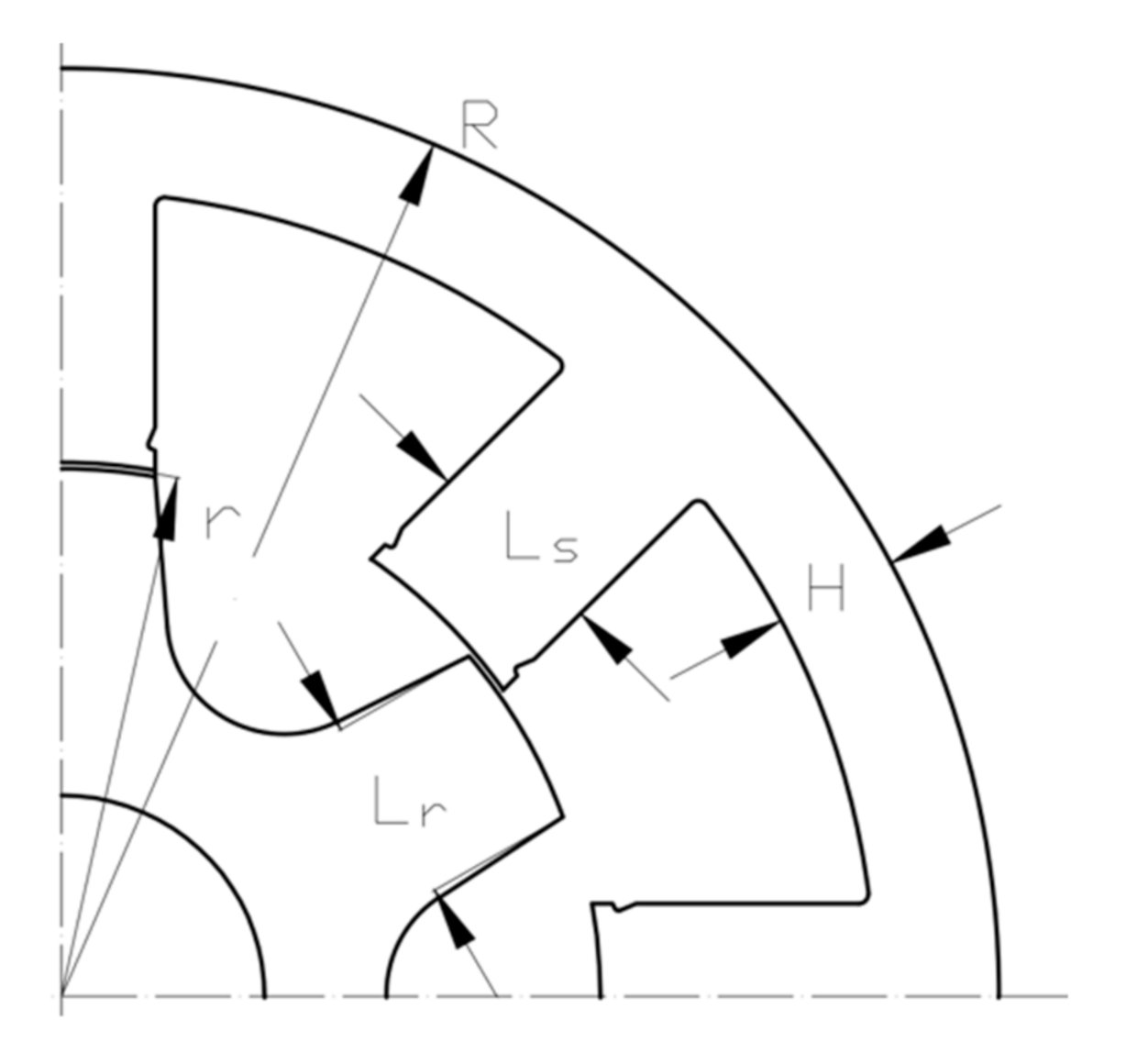
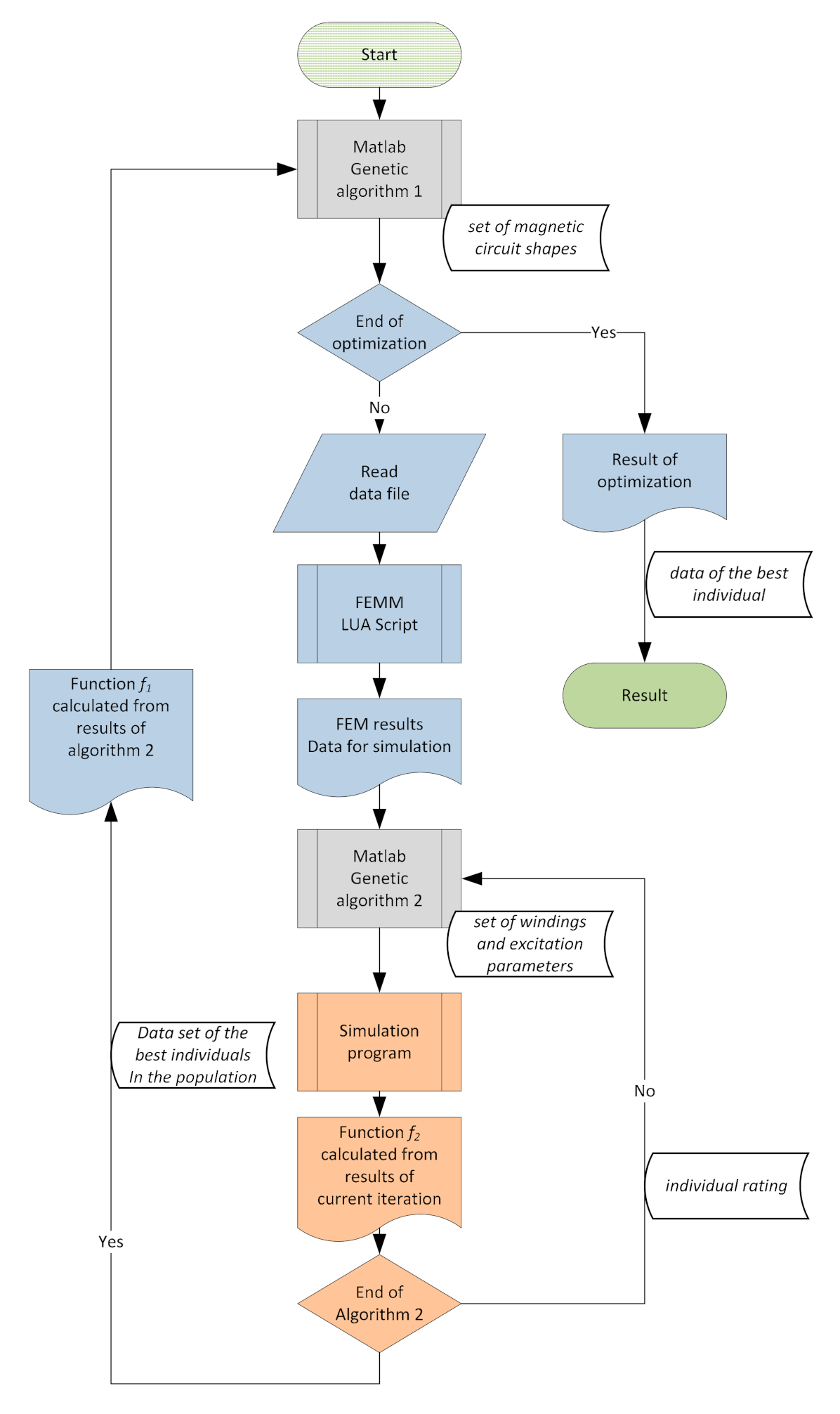
The adaptation of a switched reluctance generator to operate in a wind power plant requires multi-criteria optimization [66,67]. The optimizations of the generators were carried out in two stages using genetic algorithms, in which the objective functions were minimized. The developed algorithm performs the calculations in a set sequence. Initially, in stage 1, a population of different solutions of the generator’s magnetic circuits is generated. The characteristics of each individual from a given population, determined in this stage, are transferred to the second genetic algorithm (stage 2). In the second genetic algorithm for each individual received from stage 1, the optimization of its operating is performed. It is to fit the mechanical characteristics of individuals to the mechanical characteristics of the turbine. The best solution from stage 2 for each individual is sent to stage 1, which evaluates them. Based on these assessments, the first algorithm determines the next population of generators. Owing to the optimization of the operating conditions of the generators in stage 2, algorithm 1 evaluates the individuals taking into account the matching of characteristics. In the first stage (genetic algorithm 1), geometric variables describing the shape and size of the magnetic circuit were generated. Figure 4 shows a cross section of the magnetic circuit with marked dimensions for optimization.
For each magnetic circuit construction, the dependencies of the magnetic flux and electromagnetic torque on the rotor position angle were calculated for different values of the current density of the phase windings. These calculations were performed in a defined mesh and then saved in the form of tables, each of which contained 195 (for 15 angles values and 13 current values) computed magnetic flux or torque values. Then the table obtained for the magnetic flux was transformed into the form of the phase current density dependencies on the rotor position angle and the magnetic flux. After completing the calculations, two tables describing them were created for each structure. These tables were used for further calculations in the simulation program.
In the second stage (genetic algorithm 2) of the genetic algorithm, the parameters of the windings and the dependencies of the commutation angles on the rotational speed, which corresponded to turbine characteristics, were determined.
The windings were calculated on the basis of the stator dimensions and the diameter of the winding wire, taking the fill factor into account. In this project, typical wire diameters were used.
On the basis of the winding data (the number turns and wire diameter), the tables of current density were transformed into a form including phase current values, in which they were used for calculations in the simulation program. Then, the genetic algorithm selected the values of the generator excitation angles for the rated and maximum speeds, in accordance with the characteristics of the turbines for specified localizations. These angles were specified with a resolution of 0.25 degrees.
After completing the simulation, the program passed the data on to the genetic algorithm to calculate the value of the objective function f2 (12). The range of current values was limited by the penalty function fc(I) in the form (13), which has been included in function f2.
where
- Tm—the calculated generator torque value;
- Tmexp—the expected torque value (at rated or at maximum generator speed);
- Ps+—average power supplied to the power source;
- Ps-—average power drawn from the power source;
- Pcu—power losses in the generator windings;
- PEE—power losses in the power electronic system;
- I—phase current the root mean square (RMS) value;
- S—cross-sectional area of the winding wire.
The objective function f1 value (genetic algorithm 1) was determined in two steps. In the first step, it was checked whether the torque values obtained for the rated and maximum speed were greater than those resulting from the characteristics of the turbine. This is a necessary condition to ensure stable operation of the turbine and to prevent uncontrolled acceleration. In the second step, when the condition was met, the value of the objective function f1 was calculated (14). If this condition was not met, the penalty function, which was dependent on the difference of these values, was calculated (15).
The objective function was given in the following form:
where
- TmN—torque of the turbine at rated speed;
- TmC—torque of the turbine at cut-off speed;
- ηN—drive efficiency at rated speed;
- TmGN—torque of the generator at rated speed;
- TmGC—torque of the generator at maximum speed.
The objective function preferred highly efficient small diameter of generators in which the torque values were closest to the characteristics of the turbine and in which the permissible current density in the windings was not exceeded. The calculated values of the objective function were returned to the first stage of the genetic algorithm, which used them to determine new dimensions of the magnetic circuits. The algorithm of the developed system to optimize the parameters of switched reluctance generators is shown in Figure 5.
All calculations were performed in the developed environment for parallelized calculations. This environment was based on the author’s own programs and external applications. To calculate the magnetic field distribution, the FEMM program was used. The shape of the magnetic circuit and the computational grid were generated on the basis of data transferred from the genetic algorithm by the developed script program in the LUA language.
The genetic algorithm was implemented in the MATLAB program using the GAOT library. Calculations of the value of the objective function, data archiving, and parallelization of calculations were carried out using the authors’ own programs. The graphical presentation of the results was carried out using the authors’ own program and the external program Gnuplot (San Diego, CA, USA).
A computer cluster consisting of 10 quad-core computers was used for the calculations. Each computer performed parallel calculations for three generators. The results were saved in a database, which was used for an initial check of whether a given data set had already been calculated. If so, the results were loaded from the database without recalculation.
Each population consisted of 30 individuals. The calculations were made assuming a given number of 300 populations. The total time of calculations for one location was about 15 days.
5. Optimization Results
As a result of optimization, three generators designed to work in different locations were obtained for Nowy Sacz, Kolo, and Ustka. The number of turns and the diameter of the winding wire as well as the method of excitation were adjusted to the characteristics of the turbines at two operating points: rated speed and maximum speed. In all cases the same parameters but different excitation characteristics were obtained for the windings.
The dimensions of the magnetic circuits obtained for individual locations are summarized in Table 6. In all cases, the number of teeth in the stator was Ns = 8, in the rotor Nr = 6; the width of the air gap was 0.4 mm.
After calculating the construction parameters of the generators, their excitation characteristics, i.e., the dependence of the commutation angles on the rotational speed at which the obtained torque values were closest to the turbine characteristics, were determined.
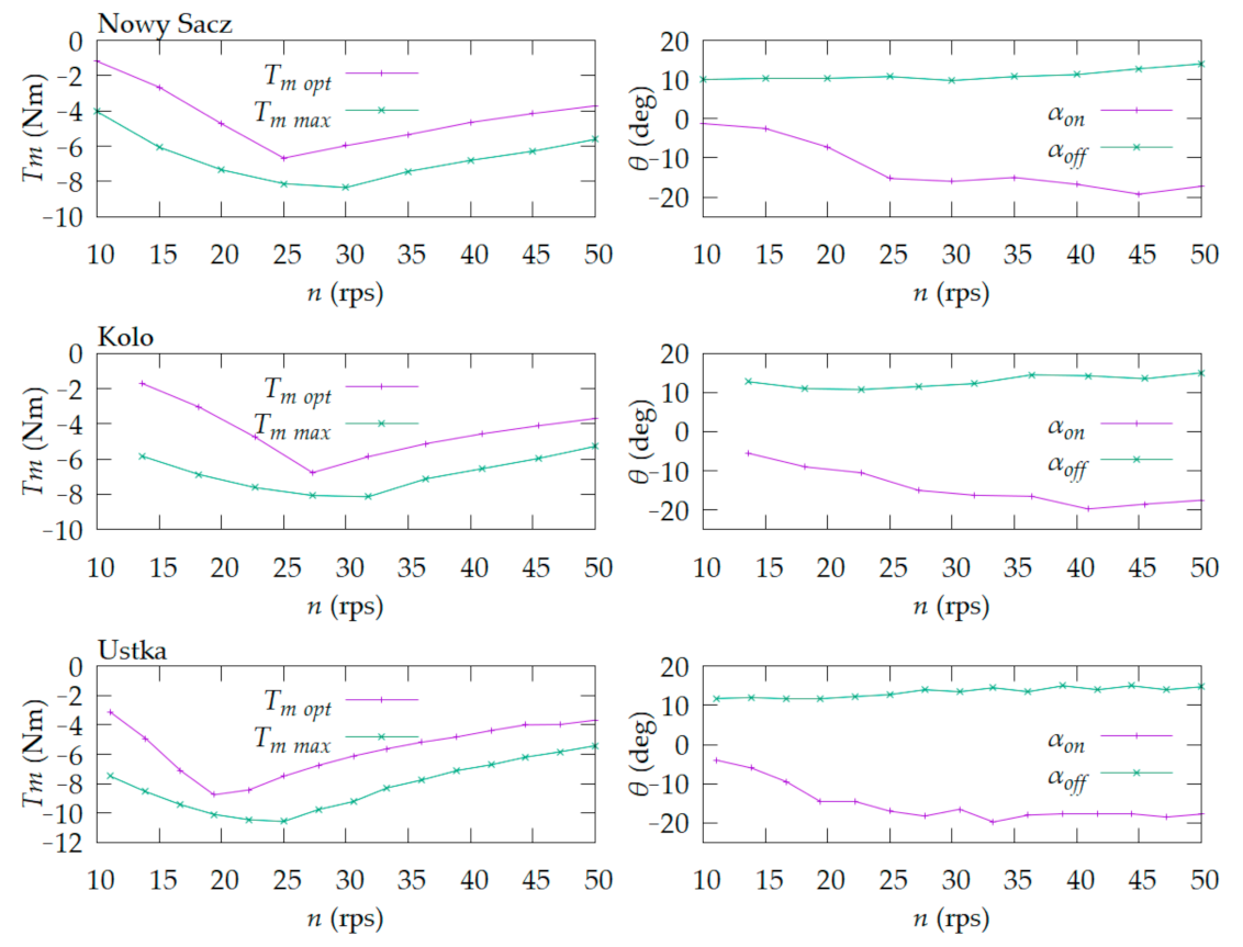
Then, for each speed, the maximum values of the torque and the commutation angles at which they were obtained were calculated. These calculations showed that in all cases the generator torque at maximum speed could be increased by modifying the excitation angles. The potential for increasing the torque above the operating characteristics of the turbines enable overloading of the turbine in order to reduce its speed. When the maximum wind speed was exceeded, it could be used to pre-brake the turbine prior to switch on mechanical braking. The observed relationships showed that, at any speed, it was possible to increase the load and reduce the speed of the turbine. These dependencies were obtained without exceeding the permissible current values. The mechanical characteristics at operating state and the maximum torque characteristics of the generators as well as the dependencies of the excitation angles on the rotational speed during normal operation are shown in Figure 6.
Then, the dependencies of the generator efficiency on the wind speed corresponding to the determined excitation characteristics were calculated. On this basis, the distributions of expected annual energy production by these generators were determined, taking their efficiency characteristics into account. Taking into account the efficiency of the generator, the total annual energy production Esim was calculated as a sum of the energy produced by the winds at each speed in annual wind speed distribution as (16).
where
- Nv—duration of winds with speed v;
- nv—generator rotational speed at wind speed v;
- Tmv—torque on the generator at wind speed v;
- ηv—generator efficiency at wind speed v.
The expected total annual energy production, after adjusting the characteristics of turbines and generators for given localizations and taking the dependencies of the generator efficiency on the rotational speed into account, is shown in Table 7. The obtained simulation values are lower than the initial estimates due to lesser efficiency at low speeds.
Then, comparative calculations were made for the same generators, optimizing the control algorithm to the characteristics of the turbine adjusted to the rated wind speed of 10 mps. For generators powered by a standard-size turbine, significantly lower values of expected annual energy production were obtained: Nowy Sacz, 0.12 MWh; Kolo, 0.54 MWh; Ustka, 1.57 MWh.
6. Conclusions
The most important factor for annual energy production is the selection of the appropriate turbine characteristics. Small commercial wind power plants adapted to a wind speed of 10–12 mps are not optimal in places with poor or even medium wind conditions.
The principle of adjusting the size of the turbine to the speed of wind with the highest energy annually, as applied in the present paper, enabled the acquisition of an important increase in the expected annual energy production in each of the considered locations, compared to generators equipped with a typical turbine adapted to a wind speed of 10 mps. The relative increase in annual energy production depended on the speed difference for which the turbines were designed.
The performed optimization proved that it is possible to adapt the construction and the method of excitation of the generator to work with turbines of this design. The simulation model employed for these calculations was verified by measurement for machines characterized by similar construction, voltage, and power, such as the designed generators. Therefore, the obtained results can be considered correct.
The highest expected value of annual energy production was obtained for the generator designed for operation in Ustka, characterized by the largest diameter, which was due mainly to the mechanical transmission ratio; however, the differences in the size of the generators were small.
Compared to generators with typical wind turbines, the relative increase in the expected value of annual energy production was the greatest for the location with the weakest winds, i.e., Nowy Sacz.
The use of a generator at this location with a typical turbine adapted to a wind speed of 10 mps is ineffective. The use of a turbine adapted to the wind speed with the highest annual level of energy resulted in several fold increase in annual energy production.
The smallest impact on expected annual energy production was obtained in an area with good wind conditions, i.e., Ustka. However, this was accompanied by the smallest increase in investment costs, due to the similar sizes of the turbines.
In all tested locations, adjusting the rated speed of the turbine to the speed of the wind with the highest annual level of energy resulted in an important increase in the expected annual energy production.
Expanding the dimensions of turbines necessitates limitation of the maximum wind speed at which they can operate (cutoff speed). Thus, these turbines do not generate energy from high-speed winds. However, accounting for the fact that such wind speeds almost never occur in these locations, this has no significant impact on annual energy production.
Regardless of location, it is necessary to adapt generator excitation characteristics to the characteristics of the turbine. The advantage of developed power plants is the potential for increasing the generator torque through changing the method of excitation. Along with the possibility of a short-term overload, this enables application of the electric brake of the turbine when the wind speed surpasses the cutoff speed. This, in turn, enables the turbine to be brought to a smooth stop in high winds.
Research has shown that the selection of the size of the turbine for the annual distribution of wind speeds has by far the greatest impact on the annual energy production. The second most important element is the appropriate selection of the excitation characteristics and windings for the characteristics of the turbine.
In the presented examples, the structure of the magnetic circuit of the SRG had the least impact on the annual energy production because for all locations similar sizes of generators were obtained.
The locations provided in the article are examples. They were chosen due to the significantly different wind conditions. The developed method can be used in different locations and wind conditions. The results of the presented examples can be used for a location with a similar annual wind speed distribution.
Author Contributions
Conceptualization, K.T., and K.W.; methodology, K.T., K.W. and A.S.; software, K.T., K.W. and A.S.; investigation, A.S.; writing—original draft preparation, K.T., K.W. and A.S.; writing—review and editing, A.T.; visualization, K.T., K.W. and A.S. All authors have read and agreed to the published version of the manuscript.
Funding
This research received no external funding.
Institutional Review Board Statement
Not applicable.
Informed Consent Statement
Not applicable.
Data Availability Statement
Not applicable.
Conflicts of Interest
The authors declare no conflict of interest.
References
- Klink, K. Climatological mean and interannual variance of United States surface wind speed, direction and velocity. Royal Meteorological Society. Int. J. Climatol. J. R. Meteorol. Soc. 1999, 19, 471–488. [Google Scholar] [CrossRef]
- Salmon, J.R.; John, L.W. A two-site correlation model for wind speed, direction and energy estimates. J. Wind Eng. Ind. Aerodyn. 1999, 79, 233–268. [Google Scholar] [CrossRef]
- Aikawa, M.; Hiraki, T.; Eiho, J. Grouping and representativeness of monitoring stations based on wind speed and wind direction data in urban areas of Japan. Environ. Monit. Assess. 2008, 136, 411–418. [Google Scholar] [CrossRef] [PubMed]
- Zhang, L.; Li, O.; Guo, Y.; Yang, Z.; Zhang, L. An investigation of wind direction and speed in a featured wind farm using joint probability distribution methods. Sustainability 2018, 10, 4338. [Google Scholar] [CrossRef] [Green Version]
- Nouri, A.; Babram, M.A.; Elwarraki, E.; Enzili, M. Moroccan wind farm potential feasibility. Case study. Energy Convers. Manag. 2016, 122, 39–51. [Google Scholar] [CrossRef]
- Ozay, C.; Melih, S.C. Statistical analysis of wind speed using two-parameter Weibull distribution in Alaçatı region. Energy Convers. Manag. 2016, 121, 49–54. [Google Scholar] [CrossRef]
- Parajuli, A. A statistical analysis of wind speed and power density based on Weibull and Rayleigh models of Jumla, Nepal. Energy Power Eng. 2016, 8, 271–282. [Google Scholar] [CrossRef] [Green Version]
- Li, P.; Hu, W.; Hu, R.; Huang, Q. Strategy for wind power plant contribution to frequency control under variable wind speed. Renew. Energy 2019, 130, 1226–1236. [Google Scholar] [CrossRef]
- Qais, M.H.; Hany, M.H.; Saad, A. Low voltage ride-through capability enhancement of grid-connected permanent magnet synchronous generator driven directly by variable speed wind turbine: A review. J. Eng. 2017, 13, 1750–1754. [Google Scholar] [CrossRef]
- Krishnamoorthy, H.; Daniel, M.T.; Ramos-Ruiz, J.; Enjeti, P.; Liu, L.; Aeloiza, E. Isolated AC–DC converter using medium frequency transformer for off-shore wind turbine DC collection grid. IEEE Trans. Ind. Electron. 2017, 64, 8939–8947. [Google Scholar] [CrossRef]
- Takeyama, Y.; Ohsawa, T.; Shimada, S.; Kozai, K. Assessment of the offshore wind resource in Japan with the ASCAT microwave scatterometer. Int. J. Remote Sens. 2019, 40, 1200–1216. [Google Scholar] [CrossRef]
- Akbari, N.; Dylan, J.; Richard, T. A cross-European efficiency assessment of offshore wind farms: A DEA approach. Renew. Energy 2020, 151, 1186–1195. [Google Scholar] [CrossRef]
- Feng, J.; Wen, Z.S. Design optimization of offshore wind farms with multiple types of wind turbines. Appl. Energy 2017, 205, 1283–1297. [Google Scholar] [CrossRef]
- Irawan, C.A.; Ouelhadj, D.; Jones, D.; Stålhane, M.; Sperstad, I.B. Optimisation of maintenance routing and scheduling for offshore wind farms. Eur. J. Oper. Res. 2017, 256, 76–89. [Google Scholar] [CrossRef] [Green Version]
- Ziemba, P.; Watrobski, J.; Ziolo, M.; Karczmarczyk, A. Using the PROSA method in offshore wind farm location problems. Energies 2017, 10, 1755. [Google Scholar] [CrossRef] [Green Version]
- Chipindula, J.; Botlaguduru, V.S.V.; Du, H.; Kommalapati, R.R.; Huque, Z. Life Cycle Environmental Impact of Onshore and Offshore Wind Farms in Texas. Sustainability 2018, 10, 2022. [Google Scholar] [CrossRef] [Green Version]
- Castro-Santos, L.; Diaz-Casas, V. Floating Offshore Wind Farms; Springer: Berlin/Heidelberg, Germany, 2016. [Google Scholar]
- Kotur, D.; Stefanov, P. Optimal power flow control in the system with offshore wind power plants connected to the MTDC network. Int. J. Electr. Power Energy Syst. 2019, 105, 142–150. [Google Scholar] [CrossRef]
- Petrović, P.; Curley, M. Detection inhomogeneities in wind direction and speed data. In Proceedings of the Fifth Seminar for Homogenization and Quality Control in Climatological Databases, Budapest, Hungary, 26–30 May 2008. [Google Scholar]
- Salahaddin, A.A.; Meeran, A.O. Surface Wind Characteristics and Wind Direction Estimation for “Kalar Region/Sulaimani-North Iraq”. Sci. J. Univ. Zakho 2013, 1, 882–890. [Google Scholar]
- Dore, A.J.; Fournier, N.; Weston, K.J.; Vieno, M. Development of a new wind-rose for the British Isles using radiosonde data, and application to an atmospheric transport model. Q. J. R. Meteorol. Soc. J. Atmos. Sci. Appl. Meteorol. Phys. Oceanogr. 2006, 132, 2769–2784. [Google Scholar] [CrossRef]
- Pishgar-Komleh, S.H.; Akram, A. Evaluation of wind energy potential for different turbine models based on the wind speed data of Zabol region, Iran. Sustain. Energy Technol. Assess 2017, 22, 34–40. [Google Scholar] [CrossRef]
- Errami, Y.; Ouassaid, M.; Maaroufi, M. Control of a PMSG based wind energy generation system for power maximization and grid fault conditions. Energy Procedia 2013, 42, 220–229. [Google Scholar] [CrossRef] [Green Version]
- Xianguo, L. Diversification and localization of energy systems for sustainable development and energy security. Energy Policy 2005, 33, 2237–2243. [Google Scholar]
- Dizdarevic, N.; Majstrovic, M.; Zutobradic, S. Power quality in a distribution network after wind power plant connection. IEEE PES Power Syst. Conf. Expo. 2004, 2, 913–918. [Google Scholar]
- Muljadi, E.; Butterfield, C.P.; Ellis, A.; Mechenbier, J.; Hocheimer, J.; Young, R.; Miller, N.; Delmerico, R.; Zavadil, R.; Smith, J.C. Equivalencing the collector system of a large wind power plant. In In Proceedings of the IEEE Power Engineering Society General Meeting, Montreal, QC, Canada, 18–22 June 2006. [Google Scholar]
- Munoz, C.; Sauma, E.; Contreras, J.; Aguado, J.A. Impact of high wind power penetration on transmission network expansion planning. IET Gener. Transm. Distrib. 2012, 6, 1281–1291. [Google Scholar] [CrossRef]
- Pagnetti, A.; Ezzaki, M.; Anqouda, I. Impact of wind power production in a European Optimal Power Flow. Electr. Power Syst. Res. 2017, 152, 284–294. [Google Scholar] [CrossRef]
- Alsmadi, Y.M.; Xu, L.; Blaabjerg, F.; Ortega, A.P.; Abdelaziz, A.Y.; Wang, A.; Albataineh, Z. Detailed investigation and performance improvement of the dynamic behavior of grid-connected DFIG-based wind turbines under LVRT conditions. IEEE Trans. Ind. Appl. 2018, 54, 4795–4812. [Google Scholar] [CrossRef]
- Gilmanur, R.; Mohd, H.A. Nonlinear control-based modified BFCL for LVRT capacity enhancement of DFIG-based wind farm. IEEE Trans. Energy Convers. 2016, 32, 284–295. [Google Scholar]
- Conroy, J.F.; Watson, R. Low-voltage ride-through of a full converter wind turbine with permanent magnet generator. IET Renew. Power Gener. 2007, 1, 182–189. [Google Scholar] [CrossRef]
- Al-Shetwi, A.Q.; Sujod, M.Z.; Blaabjerg, F. Low voltage ride-through capability control for single-stage inverter-based grid-connected photovoltaic power plant. Sol. Energy 2018, 159, 665–681. [Google Scholar] [CrossRef] [Green Version]
- Ravikiran, H.; Moger, T. Comprehensive review on low voltage ride through capability of wind turbine generators. Int. Trans. Electr. Energy Syst. 2020, 30, e12524. [Google Scholar]
- Pengxiang, X.; Fu, L.; Wang, G.; Wang, Y. A compositive control method of low-voltage ride through for PMSG-based wind turbine generator system. IET Gener. Transm. Distrib. 2017, 12, 117–125. [Google Scholar]
- Abdelkrim, B.; Khiat, M.; Allaouiand, T.; Denai, M. Power quality improvement and low voltage ride through capability in hybrid wind-PV farms grid-connected using dynamic voltage restorer. IEEE Access 2018, 6, 68634–68648. [Google Scholar]
- Chang-Hyun, P.; Jang, G. Voltage quality assessment considering low voltage ride-through requirement for wind turbines. IET Gener. Transm. Distrib. 2016, 10, 4205–4212. [Google Scholar]
- Ogawa, K.; Yamamura, M.; Ishda, M. Study for Small Size Wind Power Generating System Using Switched Reluctance Generator. In Proceedings of the 2006 IEEE International Conference on Industrial Technology, Mumbai, India, 15–17 December 2006; pp. 1510–1515. [Google Scholar]
- Narla, S.; Sozer, Y.; Husain, I. Switched Reluctance Generator Controls for Optimal Power Generation and Battery Charging. IEEE Trans. Ind. Appl. 2012, 48, 1452–1459. [Google Scholar] [CrossRef]
- Cardenas, R.; Pena, R.; Perez, M.; Clare, J.; Asher, G.; Wheeler, P. Control of a switched reluctance generator for variable-speed wind energy applications. IEEE Trans. Energy Convers. 2005, 20, 781–791. [Google Scholar] [CrossRef]
- Chen, H.; Xu, D.; Deng, X. Control for Power Converter of Small-Scale Switched Reluctance Wind Power Generator. IEEE Trans. Ind. Electron. 2021, 68, 3148–3158. [Google Scholar] [CrossRef]
- Barazarte, R.Y.; Gonzalez, G.; Hall, E. Comparison of Electrical Generators used for Wind Power Generation. IEEE Lat. Am. Trans. 2011, 9, 1040–1044. [Google Scholar] [CrossRef]
- Iwanaga, T.; Fukumoto, S.; Higuchi, T.; Yokoi, Y.; Abe, T. Analysis of a segment type switched reluctance generator for wind power generation. In Proceedings of the 2012 International Conference on Renewable Energy Research and Applications (ICRERA), Nagasaki, Japan, 11–14 November 2012; pp. 1–4. [Google Scholar]
- Korkosz, M.; Powrozek, A. The influence of control parameters on energy efficiency of switched reluctance generator for vehicle applications. E3S Web Conf. 2017, 14, 01037. [Google Scholar] [CrossRef] [Green Version]
- Ziapour, M.; Afjei, E.; Yousefi, M. Optimum commutation angles for voltage regulation of a high speed switched reluctance generator. In Proceedings of the 4th Annual International Power Electronics, Drive Systems and Technologies Conference, Tehran, Iran, 13–14 February 2013; pp. 271–276. [Google Scholar]
- Sikder, C.; Husain, I.; Sozer, Y. Switched Reluctance Generator Control for Optimal Power Generation with Current Regulation. IEEE Trans. Ind. Appl. 2014, 50, 307–316. [Google Scholar] [CrossRef]
- Le-Huy, H.; Chakir, M. Optimizing the performance of a switched reluctance generator by simulation. In Proceedings of the XIX International Conference on Electrical Machine―ICEM 2010, Rome, Italy, 6–8 September 2010; pp. 1–6. [Google Scholar]
- Nassereddine, M.; Rizk, J.; Nagrial, M. Study on excitation control of Switched Reluctance Generator for wind energy conversion. In Proceedings of the 2008 Australasian Universities Power Engineering Conference, Sydney, Australia, 14–17 December 2008; pp. 1–5. [Google Scholar]
- Cardenas, R.; Pena, R.; Perez, M.; Asher, G.; Clare, J.; Wheeler, P. Control system for grid generation of a switched reluctance generator driven by a variable speed wind turbine. In Proceedings of the 30th Annual Conference of IEEE Industrial Electronics Society, Busan, Korea, 2–6 November 2004; pp. 1879–1884. [Google Scholar]
- Dos Santos Neto, P.J.; Dos Santos Barros, T.A.; De Paula, M.V.; De Souza, R.R.; Filho, E.R. Design of Computational Experiment for Performance Optimization of a Switched Reluctance Generator in Wind Systems. IEEE Trans. Energy Convers. 2018, 33, 406–419. [Google Scholar] [CrossRef]
- Dranca, M.A.; Zaharia, M.V.; Radulescu, M.M. Modelling and transient analysis of a three-phase low-speed switched reluctance micro-wind generator. In Proceedings of the 10th International Symposium on Advanced Topics in Electrical Engineering (ATEE), Bucharest, Romania, 23–25 March 2017; pp. 196–200. [Google Scholar]
- Faradjizadeh, F.; Tavakoli, M.R.; Salehnia, M.; Afjei, E. C-Dump converter for Switched Reluctance Generator. In Proceedings of the 5th Annual International Power Electronics, Drive Systems and Technologies Conference (PEDSTC 2014), Tehran, Iran, 5–6 February 2014; pp. 597–603. [Google Scholar]
- Meiqin, M.; Jianhui, S.; Chang, L.; Guorong, Z.; Yuzhu, Z. Controller for 1kW-5kW wind-solar hybrid generation systems. In Proceedings of the 2008 Canadian Conference on Electrical and Computer Engineering, Niagara Falls, ON, Canada, 4–7 May 2008; pp. 001175–001178. [Google Scholar]
- Louie, H. Experiences in the construction of open source low technology off-grid wind turbines. In Proceedings of the 2011 IEEE Power and Energy Society General Meeting, Detroit, MI, USA, 24–28 July 2011; pp. 1–7. [Google Scholar]
- Wang, T.; He, D.; Wang, Q.; Huo, Y.; Lu, L.; Li, J. Power balance control for switched reluctance generator integrated in DC microgrid. In Proceedings of the 2015 International Conference on Advanced Mechatronic Systems (ICAMechS), Beijing, China, 22–24 August 2015; pp. 594–598. [Google Scholar]
- Gebraad, P.; Thomas, J.J.; Ning, A.; Fleming, P.; Dykes, K. Maximization of the annual energy production of wind power plants by optimization of layout and yaw-based wake control. Wind Energy 2017, 20, 97–107. [Google Scholar] [CrossRef] [Green Version]
- Maalawi, K.Y.; Badr, M.A. A practical approach for selecting optimum wind rotors. Renew. Energy 2003, 28, 803–822. [Google Scholar] [CrossRef]
- Yang, K. Geometry Design Optimization of a Wind Turbine Blade Considering Effects on Aerodynamic Performance by Linearization. Energies 2020, 13, 2320. [Google Scholar] [CrossRef]
- Pourrajabian, A.; Afshar, P.A.N.; Ahmadizadeh, M.; Wood, D. Aero-structural design and optimization of a small wind turbine blade. Renew. Energy 2016, 87, 837–848. [Google Scholar] [CrossRef]
- Perkin, S.; Garrett, D.; Jensson, P. Optimal wind turbine selection methodology: A case-study for Búrfell. Iceland. Renew. Energy 2015, 75, 165–172. [Google Scholar] [CrossRef]
- Kusiak, A.; Zheng, H. Optimization of wind turbine energy and power factor with an evolutionary computation algorithm. Energy 2010, 35, 1324–1332. [Google Scholar] [CrossRef]
- Yahia, H.; Liouane, N.; Dhifaoui, R. Differential evolution method-based output power optimisation of switched reluctance generator for wind turbine applications. IET Renew. Power Gener. 2014, 8, 795–806. [Google Scholar] [CrossRef]
- Fan, Z.; Zhu, C. The optimization and the application for the wind turbine power-wind speed curve. Renew. Energy 2019, 140, 52–61. [Google Scholar] [CrossRef]
- Heidarian, M.; Ganji, B.A. Dynamic simulation model based on finite element method for switched reluctance generator. In In Proceedings of the International Symposium on Power Electronics, Electrical Drives, Automation and Motion, Capri, Italy, 22–24 June 2016; pp. 1427–1432. [Google Scholar]
- Choi, D.; Byun, S.; Cho, Y.A. Study on the Maximum Power Control Method of Switched Reluctance Generator for Wind Turbine. IEEE Trans. Magn. 2014, 50, 1–4. [Google Scholar] [CrossRef]
- Ichinokura, O.; Kikuchi, T.; Nakamura, K.; Watanabe, T.; Guo, H.J. Dynamic simulation model of switched reluctance generator. IEEE Trans. Magn. 2003, 39, 3253–3255. [Google Scholar] [CrossRef]
- Yueying, Z.; Chuantian, Y.; Chengwen, Z. Multi-Objective Optimization of Switched Reluctance Generator for Electric Vehicles. In Proceedings of the 2018 21st International Conference on Electrical Machines and Systems (ICEMS), Jeju, Korea, 7–10 October 2018; pp. 1903–1907. [Google Scholar]
- Dos Santos, B.T.A.; Dos Santos, N.P.J.; Filho, P.S.N.; Moreira, A.B.; Filho, E.R. An Approach for Switched Reluctance Generator in a Wind Generation System with a Wide Range of Operation Speed. IEEE Trans. Power Electron. 2017, 32, 8277–8292. [Google Scholar]
Figure 1.
Annual wind speed distributions: Nowy Sacz, Kolo, Ustka.

Figure 2.
Distribution of energy supplied annually by winds of different speeds.

Figure 3.
Measured and calculated characteristics of generator electromagnetic torque.

Figure 4.
Generator cross section with marked dimensions for optimization: stator yoke thickness H (value range: 7–25 mm); stator tooth width Ls (3–50 mm); rotor tooth width Lr (3–50 mm); gap radius r (26–90 mm); stator outside radius R (40–120 mm).
Figure 4.
Generator cross section with marked dimensions for optimization: stator yoke thickness H (value range: 7–25 mm); stator tooth width Ls (3–50 mm); rotor tooth width Lr (3–50 mm); gap radius r (26–90 mm); stator outside radius R (40–120 mm).

Figure 5.
The algorithm of two-stage optimization.

Figure 6.
The dependencies of the generator torque after adaptation to the characteristics of the turbine Tm opt and the maximum torque characteristics Tm max and optimal excitation (αon and αoff angles) control characteristics of the generators designed for Nowy Sacz, Kolo, and Ustka.
Figure 6.
The dependencies of the generator torque after adaptation to the characteristics of the turbine Tm opt and the maximum torque characteristics Tm max and optimal excitation (αon and αoff angles) control characteristics of the generators designed for Nowy Sacz, Kolo, and Ustka.


Table 1.
Determined rated wind speeds and the corresponding turbine radii for the generator with rated power of 1 kW.
Table 1.
Determined rated wind speeds and the corresponding turbine radii for the generator with rated power of 1 kW.
| Location | Rated Wind Speed (mps) | Turbine Radius (m) | Turbine Rated Rotational Speed (rps) | Cutoff Turbine Speed (rps) | Ratio of Mechanical Gears (n2/n1) |
|---|---|---|---|---|---|
| Ustka | 7 | 2.15 | 3.63 | 9.33 | 5.36 |
| Kolo | 6 | 2.70 | 2.48 | 4.54 | 11.01 |
| Nowy Sacz | 5 | 3.55 | 1.57 | 3.14 | 15.92 |
Table 2.
Estimated annual energy production by wind generator in the Nowy Sacz location.
| Nowy Sacz | ||||||
|---|---|---|---|---|---|---|
| v (mps) | Tm (Nm) | Pm (W) | n (rps) | Pe (W) | Eexp (kWh) | Eexp_std (kWh) |
| 2 | 1.20 | 75 | 10 | 64 | 115 | 0 |
| 3 | 2.70 | 254 | 15 | 216 | 210 | 0 |
| 4 | 4.79 | 602 | 20 | 512 | 258 | 33 |
| 5 | 7.49 | 1176 | 25 | 999 | 244 | 31 |
| 6 | 6.25 | 1177 | 30 | 1000 | 112 | 25 |
| 7 | 5.35 | 1177 | 35 | 1000 | 37 | 13 |
| 8 | 4.68 | 1177 | 40 | 1000 | 16 | 8 |
| 9 | 4.16 | 1177 | 45 | 1000 | 7 | 5 |
| 10 | 3.75 | 1177 | 50 | 1000 | 2 | 2 |
| Expected annual energy production | 1001 | 117 | ||||
Table 3.
Estimated annual energy production by wind generator in the Kolo location.
| Kolo | ||||||
|---|---|---|---|---|---|---|
| vw (mps) | Tm (Nm) | Pm (W) | n (rps) | Pe (W) | Eexp (kWh) | Eexp_std (kWh) |
| 3 | 1.72 | 147 | 13.6 | 125 | 271 | 0 |
| 4 | 3.05 | 348 | 18.2 | 296 | 429 | 94 |
| 5 | 4.76 | 680 | 22.7 | 578 | 498 | 109 |
| 6 | 6.86 | 1175 | 27.3 | 999 | 519 | 114 |
| 7 | 5.89 | 1177 | 31.8 | 1000 | 279 | 97 |
| 8 | 5.15 | 1177 | 36.4 | 1000 | 146 | 76 |
| 9 | 4.58 | 1177 | 40.9 | 1000 | 47 | 35 |
| 10 | 4.12 | 1177 | 45.5 | 1000 | 20 | 20 |
| 11 | 3.75 | 1177 | 50 | 1000 | 1 | 1 |
| Expected annual energy production | 2210 | 546 | ||||
Table 4.
Estimated annual energy production by wind generator in the Ustka location.
| Ustka | ||||||
|---|---|---|---|---|---|---|
| vw (mps) | Tm (Nm) | Pm (W) | n (rps) | Pe (W) | Eext (kWh) | Eexp_std (kWh) |
| 4 | 3.16 | 221 | 11.1 | 188 | 317 | 109 |
| 5 | 4.94 | 431 | 13.9 | 367 | 480 | 165 |
| 6 | 7.12 | 745 | 16.7 | 633 | 546 | 188 |
| 7 | 9.64 | 1177 | 19.4 | 1000 | 593 | 206 |
| 8 | 8.43 | 1177 | 22.2 | 1000 | 336 | 174 |
| 9 | 7.49 | 1177 | 25.0 | 1000 | 279 | 206 |
| 10 | 6.75 | 1177 | 27.8 | 1000 | 158 | 158 |
| 11 | 6.13 | 1177 | 30.6 | 1000 | 149 | 149 |
| 12 | 5.62 | 1177 | 33.3 | 1000 | 88 | 88 |
| 13 | 5.19 | 1177 | 36.1 | 1000 | 61 | 61 |
| 14 | 4.82 | 1177 | 38.9 | 1000 | 26 | 26 |
| 15 | 4.50 | 1177 | 41.7 | 1000 | 18 | 18 |
| 16 | 4.22 | 1177 | 44.4 | 1000 | 14 | 14 |
| 17 | 3.97 | 1177 | 47.2 | 1000 | 8 | 8 |
| 18 | 3.75 | 1177 | 50.0 | 1000 | 2 | 2 |
| Expected annual energy production | 3033 | 1572 | ||||
Table 5.
Measured and calculated values of torque, supply current and phase current obtained for different values of commutation angles at different values of rotational speed.
Table 5.
Measured and calculated values of torque, supply current and phase current obtained for different values of commutation angles at different values of rotational speed.
| Control | Measured | Simulated | ||||||||
|---|---|---|---|---|---|---|---|---|---|---|
| αon (deg) | αoff (deg) | n (rpm) | Tm (Nm) | Is av (A) | Iph av (A) | Iph max (A) | Tm (Nm) | Is av (A) | Iph av (A) | Iph max (A) |
| −26 | −6 | 33.79 | 1.02 | 12.20 | 7.28 | 18.38 | 1.04 | 11.40 | 7.14 | 18.6 |
| −26 | −6 | 24.02 | 2.04 | 17.05 | 9.89 | 25.32 | 1.98 | 15.91 | 9.65 | 25.7 |
| −26 | −6 | 19.61 | 3.03 | 20.95 | 11.84 | 30.51 | 2.95 | 19.94 | 11.60 | 31.0 |
| −26 | −6 | 16.90 | 4.06 | 24.62 | 13.53 | 35.01 | 4.01 | 24.10 | 13.38 | 35.6 |
| −26 | −6 | 14.87 | 5.07 | 27.69 | 15.30 | 39.72 | 5.28 | 28.68 | 15.19 | 40.0 |
| −26 | −6 | 13.39 | 6.03 | 30.28 | 17.29 | 46.26 | 6.69 | 33.46 | 16.98 | 44.2 |
| −27 | −7 | 36.15 | 1.01 | 12.74 | 7.15 | 19.32 | 1.08 | 12.55 | 7.17 | 20.6 |
| −27 | −7 | 25.30 | 2.08 | 18.02 | 9.87 | 26.93 | 2.12 | 17.77 | 9.85 | 28.7 |
| −27 | −7 | 20.94 | 2.99 | 21.74 | 11.67 | 32.09 | 3.05 | 21.74 | 11.69 | 34.2 |
| −27 | −7 | 17.90 | 4.05 | 25.70 | 13.43 | 36.94 | 4.19 | 26.29 | 13.58 | 39.5 |
| −27 | −7 | 15.72 | 5.09 | 29.06 | 15.21 | 41.80 | 5.54 | 31.25 | 15.49 | 44.5 |
| −27 | −7 | 14.12 | 6.01 | 31.51 | 17.19 | 46.86 | 6.58 | 34.29 | 16.75 | 46.4 |
| −30 | −5 | 31.52 | 2.045 | 22.71 | 12.48 | 30.01 | 2.17 | 23.15 | 12.86 | 34.1 |
| −30 | −5 | 25.95 | 2.985 | 27.63 | 14.83 | 35.81 | 3.13 | 28.49 | 15.25 | 40.7 |
| −30 | −5 | 22.11 | 4.055 | 32.66 | 17.04 | 41.27 | 4.23 | 33.83 | 17.45 | 46.1 |
| −30 | −5 | 18.62 | 5.035 | 35.18 | 18.46 | 45.33 | 5.06 | 35.37 | 18.82 | 46.5 |
| −30 | −5 | 14.72 | 6.04 | 35.01 | 19.31 | 50.07 | 6.59 | 38.29 | 20.97 | 46.8 |
| Mean squared error for the presented series of calculations | δTm | δIs av | δIph av | δIph m | ||||||
| 3.6% | 4.5% | 1.3% | 6.1% | |||||||
Table 6.
Dimensions of the magnetic circuits of generators after optimization.
| Dimensions of the Generators | Symbol | Unit | Nowy Sacz | Kolo | Ustka |
|---|---|---|---|---|---|
| stator outside radius | R | mm | 63.4 | 65.4 | 69.7 |
| stator yoke thickness | H | mm | 7 | 7 | 7 |
| stator tooth width | Ls | mm | 6.7 | 6.3 | 7.3 |
| rotor tooth width | Lr | mm | 9.8 | 9.3 | 9.8 |
| radius of air gap | R | mm | 32.1 | 30.7 | 31.5 |
| thickness of air gap | D | mm | 0.4 | 0.4 | 0.4 |
| stator tooth height | Hs | mm | 24.1 | 27.5 | 31 |
| rotor tooth height | Hr | mm | 20 | 20 | 20 |
Table 7.
Estimated annual energy production and simulation result for the designed generators.
| Location of the Power Plant | Eexp (MWh) | Esim (MWh) | Esim/Eexp (%) |
|---|---|---|---|
| Nowy Sacz | 1.00 | 0.91 | 91.0 |
| Kolo | 2.21 | 2.10 | 95.0 |
| Ustka | 3.07 | 2.86 | 93.1 |
Publisher’s Note: MDPI stays neutral with regard to jurisdictional claims in published maps and institutional affiliations. |
© 2021 by the authors. Licensee MDPI, Basel, Switzerland. This article is an open access article distributed under the terms and conditions of the Creative Commons Attribution (CC BY) license (http://creativecommons.org/licenses/by/4.0/).
Share and Cite
MDPI and ACS Style
Wrobel, K.; Tomczewski, K.; Sliwinski, A.; Tomczewski, A. Optimization of a Small Wind Power Plant for Annual Wind Speed Distribution. Energies 2021, 14, 1587. https://doi.org/10.3390/en14061587
AMA Style
Wrobel K, Tomczewski K, Sliwinski A, Tomczewski A. Optimization of a Small Wind Power Plant for Annual Wind Speed Distribution. Energies. 2021; 14(6):1587. https://doi.org/10.3390/en14061587
Chicago/Turabian StyleWrobel, Krzysztof, Krzysztof Tomczewski, Artur Sliwinski, and Andrzej Tomczewski. 2021. "Optimization of a Small Wind Power Plant for Annual Wind Speed Distribution" Energies 14, no. 6: 1587. https://doi.org/10.3390/en14061587
Note that from the first issue of 2016, this journal uses article numbers instead of page numbers. See further details here.