
Exergy Analysis of Adiabatic Liquid Air Energy Storage (A-LAES) System Based on Linde–Hampson Cycle


Institute of Heat Engineering, Faculty of Power and Aeronautical Engineering, Warsaw University of Technology, 21/25 Nowowiejska Street, 00-665 Warsaw, Poland
*
Authors to whom correspondence should be addressed.
Energies 2021, 14(4), 945; https://doi.org/10.3390/en14040945
Submission received: 14 December 2020
/
Revised: 6 February 2021
/
Accepted: 8 February 2021
/
Published: 11 February 2021
(This article belongs to the Special Issue Energy Storage Systems and Conversion Processes)
Abstract
:Efficiently storing energy on a large scale poses a major challenge and one that is growing in importance with the increasing share of renewables in the energy mix. The only options at present are either pumped hydro or compressed air storage. One novel alternative is to store energy using liquid air, but this technology is not yet fully mature and requires substantial research and development, including in-depth energy and exergy analysis. This paper presents an exergy analysis of the Adiabatic Liquid Air Energy Storage (A-LAES) system based on the Linde–Hampson cycle. The exergy analysis was carried out for four cases with different parameters, in particular the discharge pressure of the air at the inlet of the turbine (20, 40, 100, 150 bar). The results of the analysis show that the greatest exergy destruction can be observed in the air evaporator and in the Joule–Thompson valve. In the case of air evaporator, the destruction of exergy is greatest for the lowest discharge pressure, i.e., 20 bar, and reaches over 118 MWh/cycle. It decreases with increasing discharge pressure, down to approximately 24 MWh/cycle for 150 bar, which is caused by a decrease in the heat of vaporization of air. In the case of Joule–Thompson valve, the changes are reversed. The highest destruction of exergy is observed for the highest considered discharge pressure (150 bar) and amounts to over 183 MWh/cycle. It decreases as pressure is lowered to 57.5 MWh/cycle for 20 bar. The other components of the system do not show exergy destruction greater than approximately 50 MWh/cycle for all considered pressures. Specific liquefaction work of the system ranged from 0.189 kWh/kgLA to 0.295 kWh/kgLA and the efficiency from 44.61% to 55.18%.

1. Introduction
With the increasing share and importance of renewable energy sources, mostly wind and solar power, there is a growing need to store energy on a large scale. It is now far from rare to have times where the generation of energy from renewables outstrips local or national demand, furthering the case for developing energy storage to balance out the differences. While small-scale storage is not a problem, large-scale storage is faced with many challenges. Current large-scale energy storage methods are outlined below.
Only two technologies of energy storage are being used on a large scale: Compressed Air Energy Storage (CAES) and Pumped Hydro Storage (PHS). In a CAES power plant, a huge volume tank is used to store compressed air. CAES technology is relatively well known, with two large facilities in operation: Huntorf in Germany (321 MW) and McIntosh in the USA (110 MW). The first one was launched in 1978, the second in 1991. An overview of the state of knowledge about CAES technology is presented in References [1,2,3,4,5]. PHS is a tried and tested technology, but large-scale use is limited by geological conditions [6,7,8].
Liquid Air Energy Storage (LAES) technology is not as well-known and tested as CAES and PHS. Unlike CAES and PHS systems, LAES technology is not limited by geological conditions and can be placed practically anywhere in the world (only access to water is required—for cooling purposes). Two facilities based on this technology are currently operational worldwide, both built by Highview Power Storage Company in the United Kingdom. The first has been in operation since 2011. The power of the system is 350 kW and the capacity 2.5 MWh. However, its simplified configuration means performance is poor, with an efficiency of about 8% [9]. The experimental measurements of operation and mathematical model of this prototype installation are presented in Reference [10]. The second plant, near Manchester, has been in operation since 2018. The power of the system is 5 MW and capacity 15 MWh.
Recently, a large group of scientists began dealing with the subject of LAES, assessing it as prospective. In Reference [11], a conceptualization and thermodynamic analysis of the LAES was presented. The efficiency of the presented system was 49%. The system for storing energy using liquefied air, but in a high-pressure state, is presented in Reference [12].
In other research [13,14], a hybrid solution was presented combining CAES and LAES with the possibility of converting compressed air (50 bar) at ambient temperature into liquid air at ambient pressure. The system has the ability to perform the reverse process. According to the authors of those papers, this configuration is cheaper than the LAES system and the CAES system (with the use of artificial compressed air tanks). A preliminary analysis [13] demonstrated computational efficiency of 53%, but subsequent calculations [14] showed energy storage efficiency of 42%.
In the available literature [15], the CAES system was also compared with systems based on various liquefied gases, such as carbon dioxide, air, and nitrogen. The authors state that energy storage facilities using liquefied gases are the best technologies for storing energy on large scale. In Reference [16], the authors performed an economic analysis of an energy storage unit based on liquid air and compressed air. The analysis was made for various mixes of liquid and gaseous air (from 0 to 100%).
Carbon dioxide is considered a possible working fluid in LAES systems. An energy storage unit using liquid CO2 as a working fluid and operating in a closed circuit was presented in Reference [17]. The system is equipped with two tanks for liquid CO2, one high pressure, the other low pressure. During the charging process, the high-pressure tank was filled and the low-pressure tank was emptied; during unloading, the opposite process occurred. The author reported that the system had 56.64% efficiency.
In Reference [18], a variety of cryogenic energy storage systems were compared in terms of collaboration with distributed sources. According to the authors of the above-cited article, the best solution for liquefying air is the Claude cycle equipped with a Joule–Thompson valve and a turbine. The Linde–Hampson cycle equipped with only the Joule-Thompson valve has worse operating parameters. On the other hand, the authors of this article state that the use of cold storage can change this relationship. The use of this element reduces by several times the work required to liquefy air. Part of the working fluid entering the turbine in the Claude cycle is used only to cool the air before the Joule–Thompson valve, e.g., recuperating, at the same time, energy that can be harnessed to drive the compressor.
An interesting energy storage system can be found in Reference [19]. This solution uses the Rankine cycle, with air as the working medium. The system can operate continuously. The air is constantly liquefied and then pumped, heated, and finally expanded in the turbine. This system is equipped with a cryogenic tank for liquid air, which stores energy. The computational efficiency of such a system ranges from 20% to 50%.
A hybrid system for the production and storage of energy based on the Parabolic Trough Solar Collector Power Plant and Liquid Air Energy Storage is shown in Reference [20]. This system includes two heat storage tanks (high temperature and low temperature), which are the elements connecting the solar power plant with the LAES system.
Systems for storing energy with the use of, inter alia, liquid air combined with liquefied natural gas (LNG) regasification process are shown in References [21,22,23]. As in Reference [12], in articles [21,22,23], liquefied air is stored under high pressure. The system that uses cold from the LNG regasification process for air liquefaction in the LAES system is also shown in Reference [24], but in this case, the liquefied air was stored under low pressure.
On the other hand, the use of the LAES system for cooling purposes is shown in Reference [25]. The round-trip efficiency of the system achieved in this case was 45%.
More about energy storage through liquid air can be found in the previous research of the authors [26,27].
As can be seen from the above, many analyses have already been carried out. Work on LAES technology is carried out in many research centers around the world. Scientists from these centers very often cooperate with each other, which was shown in the bibliometric analysis of articles on LAES presented in Reference [28].
The available literature contains articles on the exergy analysis of LAES but based on a liquefaction cycle using an expander (Claude cycle) [29,30,31,32]. In this article, the authors will focus on multivariant exergy analysis of the A-LAES system based on the Linde–Hampson cycle. This article conducts an exergy analysis for many variants to show the cause of thermodynamic imperfections. It is shown how the destructions of exergy migrate inside the modeled LAES system depending on changing parameters. The advantages of exergy over energy analysis are described in the following sections.
This article also investigates the effect of cooling thermal oil after the discharging part of the A-LAES system to reduce the energy consumption of compressors in the charging system. In some cases, reducing energy consumption in the charging system gives better energy effects (greater efficiency) than forcing a high temperature in the discharge system.
2. Materials and Methods
Energy analysis is based on the first law of thermodynamics, the conservation of energy: the balance of energy supplied and received from the system. Energy leaving the system can be broken down into losses and usable energy. Typically, efficiencies are used to evaluate such systems, which are a fraction of the usable energy for the energy fed into the system. Thus, system losses cannot be properly identified.
In contrast, exergy is the maximum work that can be performed by a stream or system and can be an indicator of the quality or utility of energy. Unfortunately, all real processes are irreversible. Exergy is preserved in a reversible (ideal) process and is consumed in an irreversible (real) process.
According to the authors in Reference [33], the following definition can be cited: “Matter exergy is the maximum work that this matter can do in a reversible process, in which the environment is used as a source of worthless heat and worthless substances, if at the end of this process all the forms of matter participating in it attain a state of thermodynamic equilibrium with the common components of the environment.”
The concept of exergy is gaining increasing recognition in the scientific community due to the fact that the first law of thermodynamics is insufficient to describe energy systems. This law does not allow for the description of imperfections of individual elements of the system.
Exergy analysis brings the following benefits [34]:
- Exergy efficiency defines the actual quality of the system, providing useful information for assessing energy cycles. It helps identify causes for losses and where they occur.
- Exergy analysis is useful in the evaluation of multi-product systems, such as cogeneration or trigeneration systems.
- Exergy analysis helps reduce environmental pollution and improves economic indicators.
- Exergy analysis gives a deeper understanding of the concept of energy savings and an energy crisis.
- Exergy analysis helps optimize the system faster and more precisely.
The calculations shown in the following paragraph were done in Aspen HYSYS software [35]. The model of the working medium relied on Peng–Robinson equation of state [36]:
where: p—pressure, R—gas constant, T—absolute temperature, v—molar volume, a—attraction parameter, b—van der Waals co-volume.
Exergy destruction could be described using the Gouy–Stodola equation [33]:
where: T0—ambient temperature in Kelvin, Σ∆S—the sum of entropy changes in
the system.
The outflow specific exergy loss for the pneumatic engine is [33]:
where: hout—specific enthalpy of working fluid at outlet, h0—specific enthalpy of working fluid in ambient conditions, sout—specific entropy of working fluid at outlet, s0—specific entropy of working fluid in ambient conditions.
Furthermore, the outflow exergy loss (δBoutflow) is obtained by multiplying outflow specific exergy loss (δboutflow) by mass of working fluid. Exergy destruction in the elements of the modelled system is described below:
Compressors:
where: Eelc—energy consumed by compressor.
Turbines:
where: Eelt—energy from turbine.
Heat exchangers:
where: outcs index means cold side outlet, ouths index means hot side outlet, incs index means cold side inlet and inhs index means hot side inlet.
Air reservoir, tanks, valves:
Pumps:
where: Eelp—energy consumed by pump.
Mixer:
The exergy efficiency of any energy system can be written as follows:
where: —total exergy of products, —total exergy of “fuel”.
3. Model Description
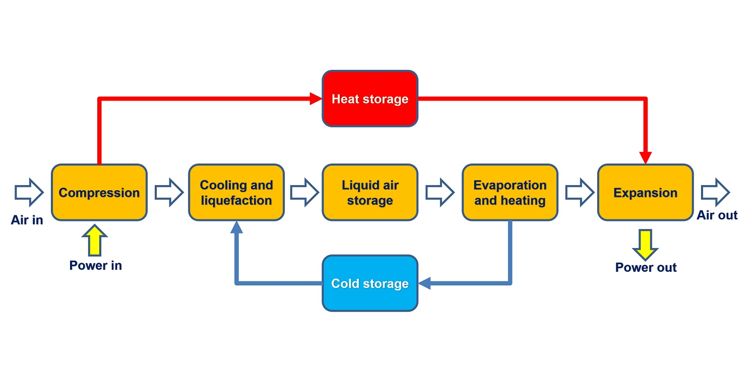
The technology of energy storage with the use of liquefied air includes a liquefaction module, a module for recovering energy from the liquefied air and elements allowing for its storage. During charging, excess electricity from the grid is used to liquefy the air. In this process, air is compressed and then cooled down, and throttled or expanded in a cryogenic turbine (depending on the liquefaction cycle used) to the point where it changes from its original gaseous form to a liquid state. The liquefied air is stored. When the demand for electricity in the grid increases, the pressure of the liquid air is increased by the pump. The air under pressure is heated and evaporates at the expense of the supplied heat. Gaseous air is used to drive turbines to generate electricity. Depending on the configuration of the system, it is possible to use additional fuel (system with a combustion chamber) to significantly increase the temperature of the medium in front of the turbine, or to expand the air without using fuel (adiabatic system).
During the process of evaporating the air, the heat supply is cooled to a low temperature. In order to improve the efficiency of the system, the cold must be stored and used later in the liquefaction process. The cold store contributes to the improvement of efficiency in both systems with and without a combustion chamber.
In adiabatic systems, apart from the aforementioned cold store, it is also necessary to use a heat store generated as a result of the air compression process. This heat is then used in the LAES discharge cycle. In order to make better use of the heat from the storage, it is necessary to divide the gas turbine (and thus the expansion process) into several parts. Between each of them, and also before the first turbine, heat exchangers should be installed, fed with the medium from the heat store.
The possibility of storing cold from the air evaporation process and its use in the liquefaction process is a key feature that determines the achievement of the high efficiency of energy storage in the discussed technology.
In the LAES system presented in the article, a cold store based on liquid agents was proposed. The idea of such storage is based on the use of two “cold” and “hot” tanks constituting one cold store. When loading the cold store, i.e., unloading the energy store, the medium from the “hot” tank, through the air heater in the discharge section, goes to the cold tank. Similarly, during the discharge of the cold store, i.e., the charging of the energy store, the factor from the “cold” tank goes to the multi-stream heat exchanger, where it is heated and then stored in the hot tank.
It is difficult to find the medium or factors that stay liquid at such low temperatures and ambient pressure. Meeting these conditions allows for easy storage of the cooling medium and ensures effective heat exchange with air. The analysis shows that the only factors meeting the above conditions are hydrocarbon substances.
In the analyzed LAES system, a two-stage cold store was proposed, working in accordance with the idea presented above. The following were used as cooling carriers:
- R290 refrigerant in the first stage, i.e., liquid propane;
- liquid methanol in the second stage.
It was assumed that the temperature of the medium in cold tanks will be, respectively:
- −185 °C for R290;
- −60 °C for methanol.
However, in hot tanks:
- −60 °C for R290;
- 25 °C for methanol.
As a working medium in a heat store, Therminol 55 oil was used. It is a synthetic oil used in the heat storage system [37] and its operating range is −28 °C ÷ 315 °C [38].
The model was built using Aspen HYSYS [35] software by the authors of this paper [26]. The energy storage system is charged during the valleys of load of the power system and discharged at peaks.
It was assumed that the charging time to discharge time ratio is 2 (charging time—eight hours; discharge time—four hours).
Compared to the previous article prepared by the authors [26], the structure of both the charging and discharging systems was changed. In the charging system, just before the cold box, an additional air cooler (AAC) was added to reduce the air temperature (this exchanger cools the air using cold water). In the discharging system, a heat exchanger (HEX4), fed with oil leaving the HEX5, HEX6, and HEX7 heat exchangers, was added just after the air superheater to preheat the air before HEX5–7 heat exchangers. An additional oil cooler (AOC) was added to the discharge system, which is fed with cold water to reduce the oil temperature. The energy consumption of the compressors is reduced by reducing the temperature of the oil entering the charging system. In some cases, reducing energy consumption in the charging system gives better energy effects (greater efficiency) than forcing a high temperature in the discharge system, which was also examined in this article. The pressure ratios of individual parts of the compressors in the charging system were selected so that the oil at the outlet of the HEX1, HEX2 and HEX3 heat exchangers had the same temperature (in order to avoid the destruction of exergy resulting from mixing factors of different temperature). The pressure drops of individual parts of the turbine were selected to obtain the greatest efficiency of the system. Due to the fact that the amount of heat from the charging system significantly exceeded the needs of the discharging system, the condition for equal oil temperature at the outlet could be maintained by changing the properties (deterioration of temperature differences at the outlet) of the HEX5–7 heat exchangers.
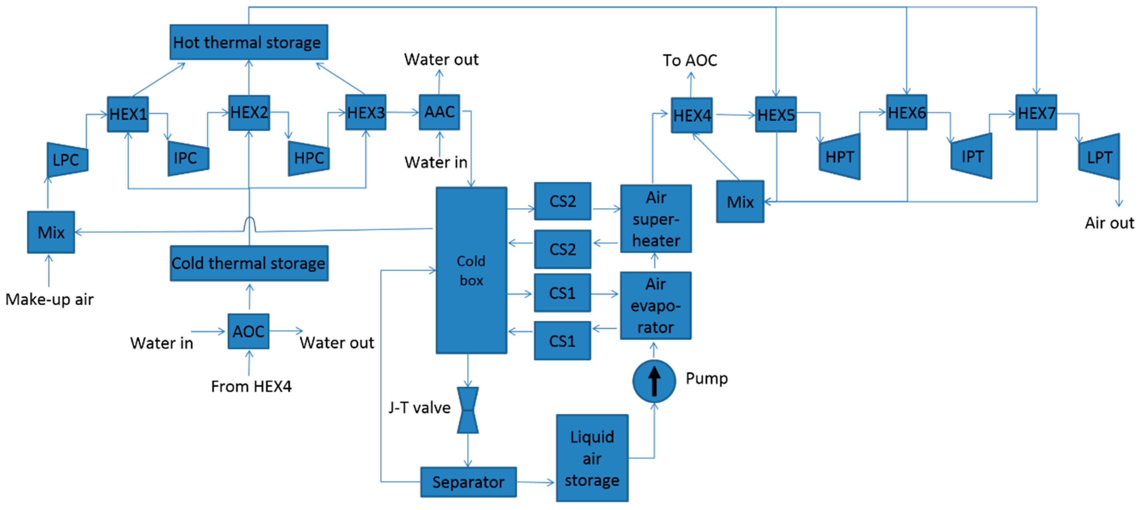
The model presented in this article uses more conservative parameters of individual system elements than in Reference [26]. The layout of the analyzed system equipped with an additional air cooler (AAC) and additional oil cooler (AOC) is presented in Figure 1.
Based on the described model, four cases were under investigation. The cases are differentiated by their basic operating parameters. The parameters characterizing the cases are presented in Table 1.
Table 2, Table 3, Table 4 and Table 5 present detailed parameters of the analyzed cases, such as: pressure drop on the cold side of the heat exchangers, pressure drop on the hot side of the heat exchangers, and minimum temperature difference are presented for all four analyzed cases.
As for the pressure drops in individual exchangers, higher pressure drop values were assumed on the oil and water side than on the air side due to the higher density of oil and water compared to air. On the air side, the principle was also followed that greater pressure drops are obtained for streams with higher pressure.
As the A-LAES system consists of a number of devices that are technologically mature, the efficiency of individual devices and components was also assumed based on the knowledge of the authors. The efficiencies are presented in Table 6.
The influence of AAC and AOC
In order to compare the influence of AAC and AOC on the performance of the modulated A-LAES system, calculations were made for models without AAC or with reduced cooling of thermal oil for all considered cases. The summary of these calculations is shown in Table 7.
The complete elimination of AOC was not possible due to the fact that the thermal oil should not exceed 300 °C (the maximum possible operating temperature of this oil is 315 °C).
For all considered cases, the use of AAC brought benefits (both in terms of efficiency and specific liquefaction work). Removing this component resulted in a decrease in efficiency from 0.33% to 2.66% and an increase in specific liquefaction work by 0.001 ÷ 0.008 kWh/kgLA.
The situation is not so clear when it comes to reducing thermal oil cooling after discharging part of A-LAES. From the point of view of the specific work, this cooling always gives positive results (reduction by 0.017 ÷ 0.031 kWh/kgLA). However, in the case of efficiency for cases I, II, and IV, this cooling causes a decrease in efficiency (from 0.28% to 2.35%). For case III, cooling the thermal oil in the AOC increases the efficiency by 0.76%. Fortunately, case III is characterized by the maximum round trip efficiency for the modeled A-LAES system.
4. Results
Energy analysis was carried out in a previous article written by the authors [26]. In the same paper, four cases analyzed here were also selected on the basis of energy analysis. Compared to the previous system, the structure of the system presented in this paper has been slightly modified, which was described in detail in the previous chapter and characterized in Figure 1. This article deals with exergy analysis, so the results concerning it are presented below.
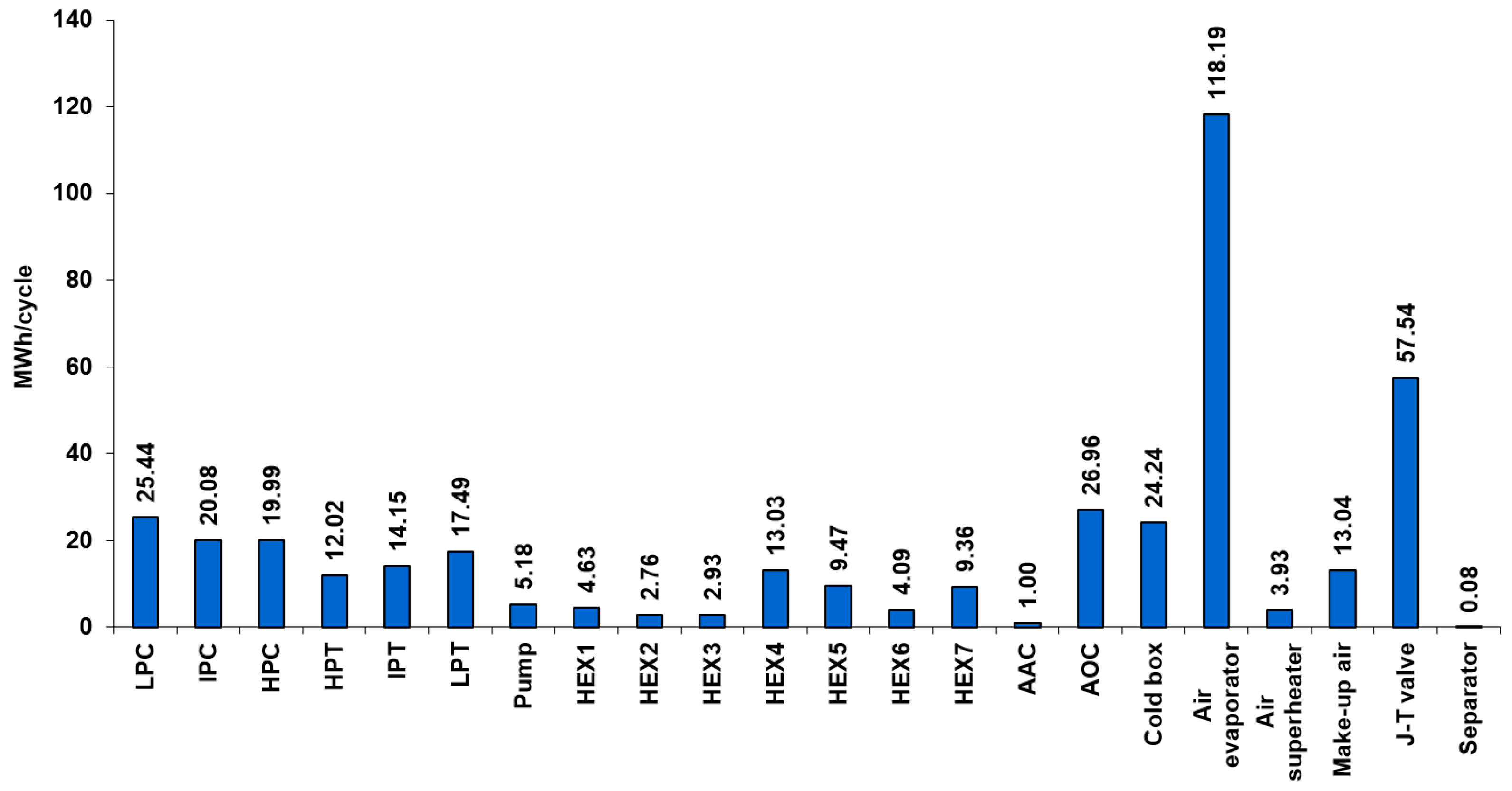
Destructions of exergy on the components of the adiabatic LAES system for case I (120 bar in the loading part and 20 bar in the unloading part) are shown in Figure 2.
The greatest destruction of exergy for this case occurs at the air evaporator and then at the J-T valve. The big sources of exergy destruction are also: cooler 2, low-pressure compressor part, cold box, medium and high-pressure compressor part, medium and low-pressure turbine part, make-up air mixing, HEX4, and high-pressure turbine part. Exergy destructions of the other elements of the system are small. Low pressure in the charging system means that the share of throttling in total exergy destruction is not dominant. On the other hand, at low pressure in the discharge system, the temperature differences in the evaporator are high, which causes large exergy destruction.
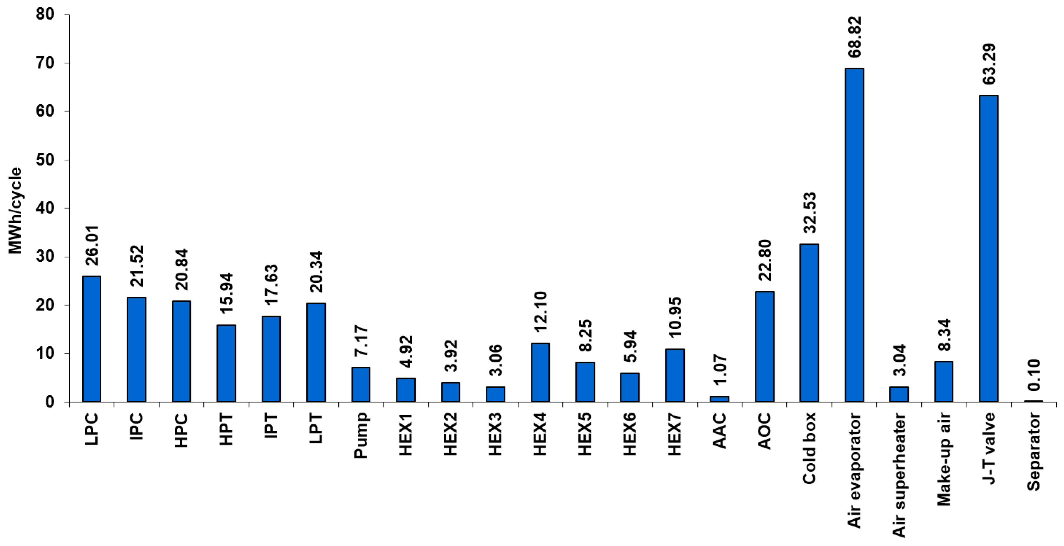
Figure 3 shows the exergy destructions of A-LAES system elements for case II (120 bar in loading part and 40 bar in unloading part).
As in the previous case for case II, the greatest destruction of exergy for this case occurs at the air evaporator and then at the J-T valve. However, this difference is insignificant. Other important sources of exergy destruction are: cold box, low-pressure compressor part, cooler 2, medium and high-pressure compressor part, individual turbine parts, HEX4, and HEX7. The destruction of exergy in other elements of the system is less significant.
The increase of pressure in the discharging part of the system reduced the destruction of the exergy in the evaporator. It also caused a reduction in the amount of cold obtained during discharging, which means that the air in the charging system has to circulate more, which increases the destruction of exergy on the J-T valve (despite the same pressure in the charging system).
The increase in pressure in the discharge system also increases the power obtained from it, which compensates for the increase in the needs of the charging system.
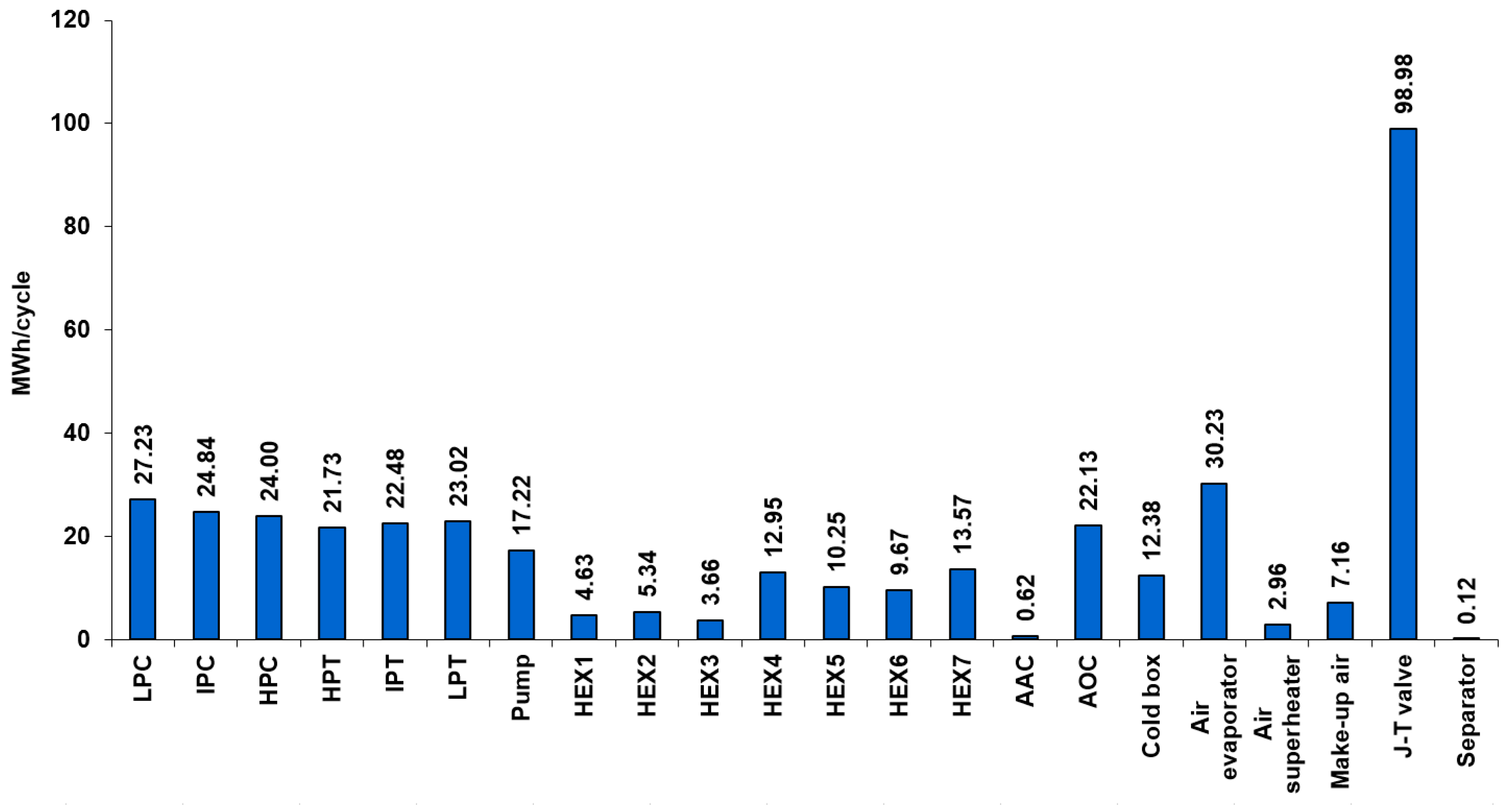
Exergy destructions in the components of the adiabatic LAES system for case III (200 bar in the loading part and 100 bar in the unloading part) are shown in Figure 4.
For this case, the destruction of exergy in the J-T valve greatly exceeds the destruction in the other components of the system. Significant sources of exergy destruction in the system are: air evaporator, individual parts of the compressor, low and medium-pressure turbine part, cooler 2, high-pressure turbine part, pump (due to relatively high pressure in the discharge system), HEX7, HEX4, cold box, and HEX5. Destruction in the rest of the system is less significant.
A further increase in pressure in the discharging system causes a further decrease in the heat of evaporation of the air (but at the same time an increase in the power of the turbines) and a decrease in the amount of cold recovered during discharge. Reducing the amount of cold during discharging makes it necessary to increase the pressure during charging in order to efficiently conduct the air liquefaction process, which is the cause of the increase in exergy destruction at the J-T valve.
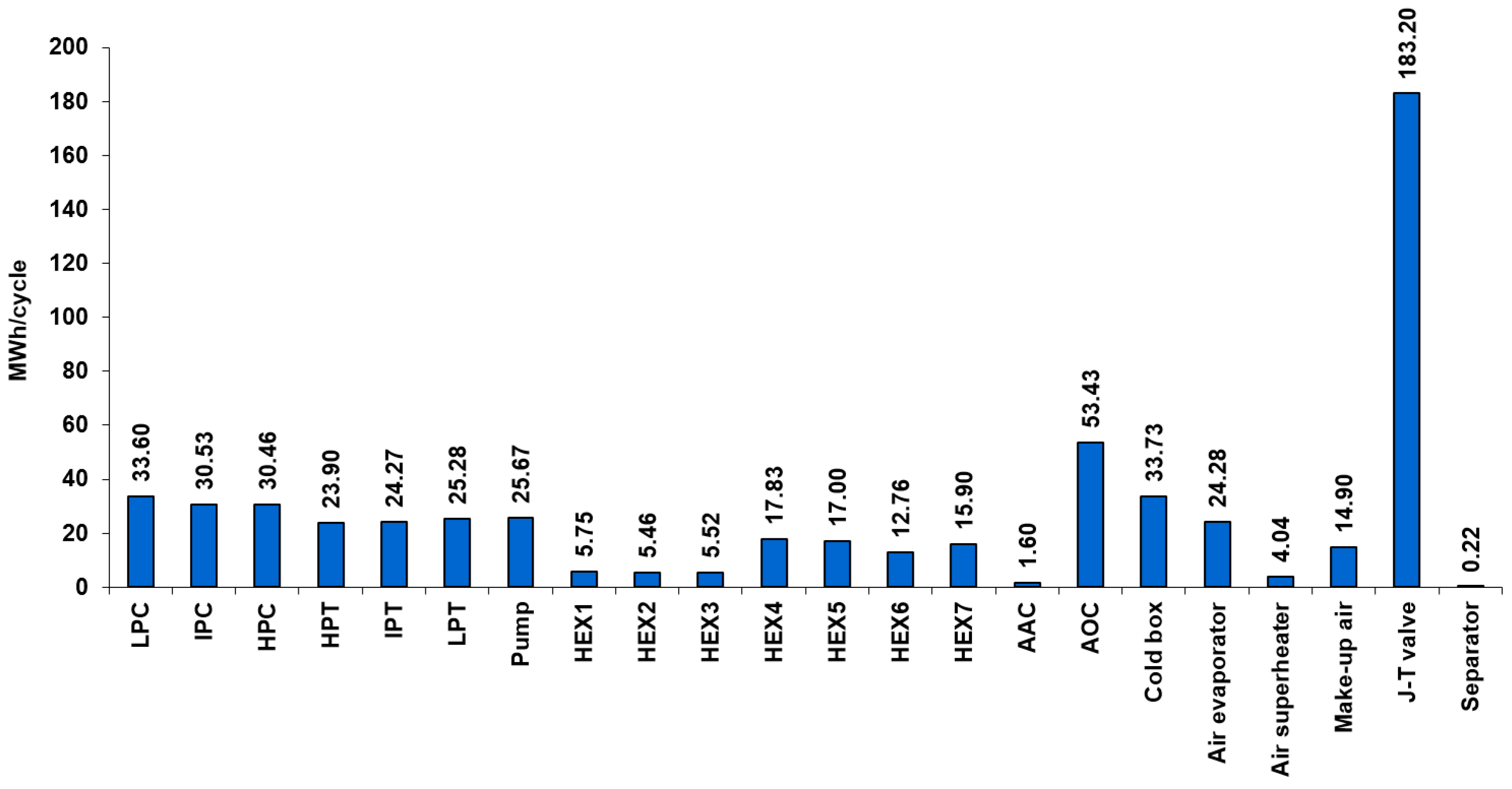
Figure 5 shows the exergy destructions of A-LAES system elements for case IV (300 bar in the loading part and 150 bar in the unloading part).
The destruction of exergy in the J-T valve is even greater here than in the previous case. Due to the very large amount of heat generated in the charging system, which is not consumable in the discharge system, we can observe much greater destruction of exergy in cooler 2 than in the previous cases (the oil leaving the discharge system is cooled at very large temperature differences). Other sources of significant exergy destruction are: cold box, individual parts of the compressor, pump (even higher pressure in the discharging system than in case III), low-pressure turbine part, air evaporator, medium and high-pressure turbine part, HEX4, HEX5, HEX7, mixing (make-up air), and HEX6. The other elements of the system are characterized by less destruction of exergy.
In the last case, the processes described in the previous case are even more intensified (lower heat of vaporization of the air during discharging, which causes a reduction in exergy destruction in the evaporator and greater destruction of exergy on the J-T valve during charging due to high pressure).
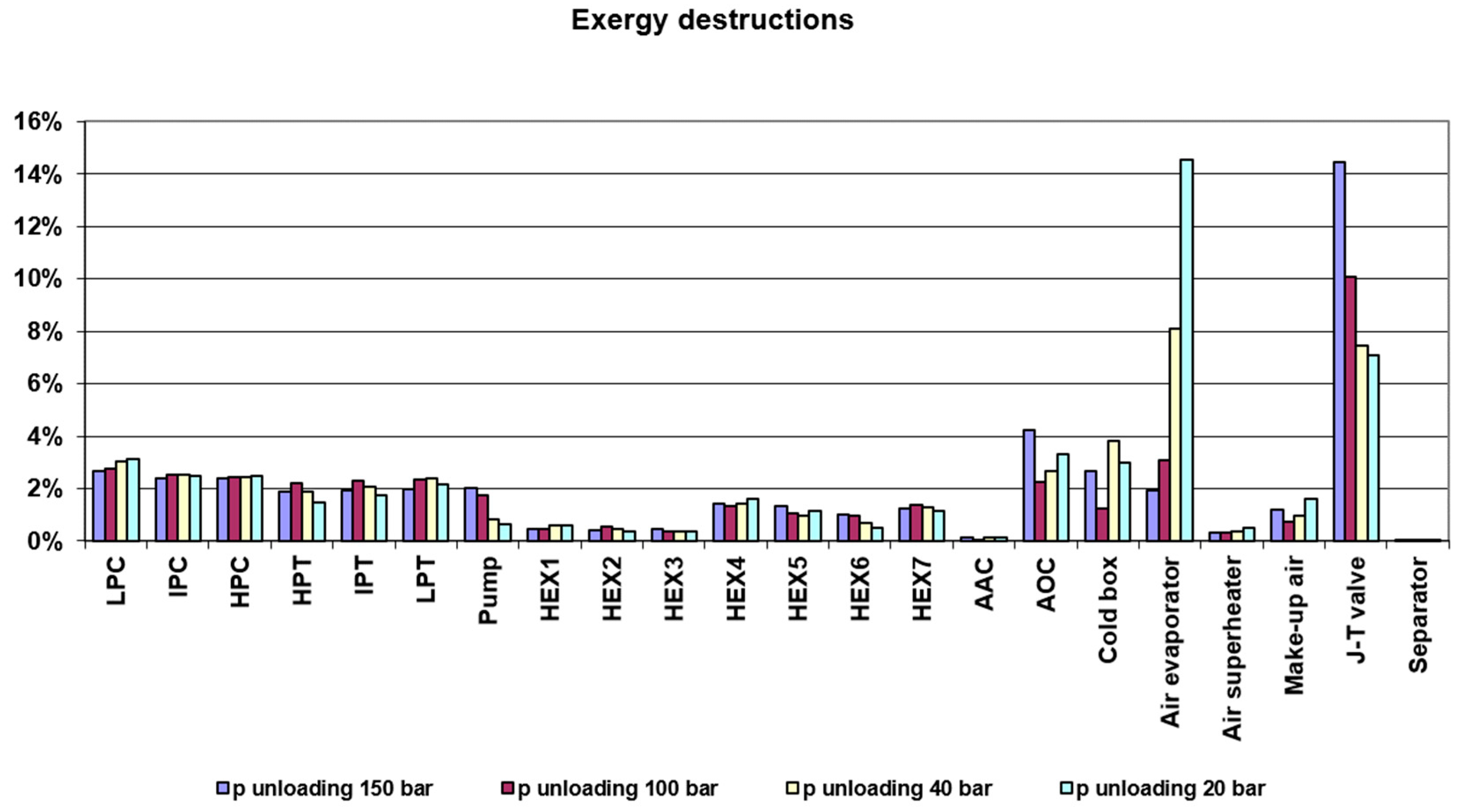
The figures shown above are in absolute units. In order to better compare the cases analyzed in this article, they must be presented in relative units.
Figure 6 shows a comparison of all cases as a percentage of exergy delivered to each system.
For high pressures in the charging system (case III and case IV), from the point of view of exergy analysis, the greatest destruction of exergy can be observed on the Joule–Thomson valve, which from the point of view of the energy balance is not a source of losses (as throttling is an isenthalpic process). For lower pressures in the charging system (case I and case II), the greatest source of exergy destruction is the air evaporator and then the J-T valve. The decrease in the share of evaporator exergy destruction together with an increase in pressure in the discharge system is caused by a decrease in the heat of vaporization (with an increase in pressure) of air. However, it is connected with the necessity to increase the pressure in the charging system in order to make the air liquefaction process more efficient.
For all the cases considered, compressors and turbines are also a noticeable source of exergy destruction. As the pressure in the discharge system increases, the share of exergy destruction in the cryogenic pump also increases.
Table 8 shows the exergy efficiency, unloading power, storage capacity, and specific liquefaction work of the modeled A-LAES system for all considered cases.
The exergy efficiency values ranged from 44.61% to 55.18%, peaking in case III. For case IV, the share of exergy destruction on the J-T valve is too high—which causes a decrease in exergy efficiency.
As there is only electrical energy at the input and output of the system, the energy efficiency here will be equal to the exergy efficiency. The exergy of the fuel will be solely the electric energy supplied to the compressors, and the exergy of the product—the energy obtained from the turbines minus the energy used by the cryogenic pump.
The specific liquefaction work for the modeled system ranged from 0.189 kWh/kgLA to 0.295 kWh/kgLA and was the lowest for the cases with lower pressure in the charging part. It can be seen that the optimum efficiency is not achieved for the same parameters as the minimum specific work of liquefaction.
In the available literature, it is possible to find systems based on the Claude cycle (or the modified Claude cycle) with lower efficiency than the system presented in this article: [31]—48%, [29]—40%. Systems based on the modified Claude cycle with comparable efficiency to case III of this article can also be found. Reference [39] shows two systems based on the Kapitza cycle (which is also a modification of the Claude cycle): a 54.16% efficient system with cold storage with a liquid medium and a system with packed bed cold storage with an efficiency of 60.48%. The comparison of the results with other adiabatic LAES systems is shown in Table 9.
The specific work of liquefaction for these papers are: [31]—972 to 1019 kJ/kg LA (from 0.270 to 0.283 kWh/kgLA), [39]—714.73 kJ/kgLA (0.199 kWh/kgLA) for system with a cold storage with a liquid medium and 641.46 kJ/kgLA (0.178 kWh/kgLA) for system with packed bed cold storage.
Claude cycle is much better for the standalone liquefaction system than Linde–Hampson. However, when a cold source is available (e.g., stored from the LAES discharging system) the liquefaction work of the Linde–Hampson cycle drops (especially visible in low-pressure systems—see Table 8 for cases I and II). Then, both systems become competitive with each other. The advantage of Linde–Hampson system is its much simpler structure compared to the Claude system—which makes it cheaper and more reliable.
The results in Table 9 also shows that there is potential for even greater efficiency of the LAES system presented in this article by using a packed bed in the cold storage, where the air can be in direct contact with the storage medium.
5. Discussion and Conclusions
In the article, an exergy analysis was carried out for four cases of adiabatic LAES system with the same structure: case I—120 bar in the charging system and 20 bar in the discharging system, case II—120 bar in the charging system and 40 bar in the discharging system, case III—200 bar in the charging system and 100 bar in the discharging system, case IV—300 bar in the charging system and 150 bar in the discharging system. These cases were selected in the previous article of the authors [26]. In relation to the previous article, the structure of the system was slightly modified (an air cooler was added in the charging part and an oil cooler was added in the discharging part) and more conservative parameters of individual elements of the modeled system were used.
The amount of heat generated in the charging system significantly exceeds the needs of the discharging system. The energy consumption of the compressors is reduced by reducing the temperature of the oil entering the charging system. Reducing energy consumption in the charging system gives better energy effects (greater efficiency) than forcing a high temperature in the discharge system.
Exergy efficiency of 44.61% to 55.18% was achieved. The highest exergy efficiency was obtained for case III. For high pressures in the charging system (case III and case IV), the greatest destruction of exergy can be observed in the Joule–Thomson valve. For lower pressures in the charging system (case I and case II), the greatest source of exergy destruction is the air evaporator and then the J-T valve. For all the considered cases, compressors and turbines are also a noticeable source of exergy destruction. The cryogenic pump is only a significant source of exergy destruction if the pressure in the discharge system is high.
Specific liquefaction work for the modeled system ranged from 0.189 kWh/kgLA to 0.295 kWh/kgLA. This parameter increased with increasing pressure in the charging system.
In subsequent research, it is planned to modify the presented system by using a packed bed medium in the cold storage to increase the efficiency of the system.
Author Contributions
Conceptualization, M.W., P.K., and L.S.; methodology, P.K. and L.S.; software, P.K. and L.S.; formal analysis, M.W., P.K., and L.S.; investigation, M.W., P.K., and L.S.; writing—original draft preparation, M.W. and L.S.; writing—review and editing, P.K., M.W., and L.S.; visualization, M.W. and L.S.; project administration, M.W.; funding acquisition, M.W. All authors have read and agreed to the published version of the manuscript.
Funding
This research received no external funding. The publication is the result of an Internal Grant for employees of the Warsaw University of Technology in 2020.
Institutional Review Board Statement
Not applicable.
Informed Consent Statement
Not applicable.
Data Availability Statement
The data presented in this study are available on request from the corresponding author.
Acknowledgments
The authors would like to thank the Scientific Council of the Discipline of Environmental Engineering, Mining and Power Engineering and the Dean of the Faculty of Power and Aeronautical Engineering of the Warsaw University of Technology for their support.
Conflicts of Interest
The authors declare no conflict of interest.
References
- Luo, X.; Wang, J.; Dooner, M.; Clarke, J.; Krupke, C. Overview of current development in compressed air energy storage technology. Energy Procedia 2014, 62, 603–611. [Google Scholar] [CrossRef] [Green Version]
- Lund, H.; Salgi, G.; Elmegaard, B.; Andersen, A.N. Optimal operation strategies of compressed air energy storage (CAES) on electricity spot markets with fluctuating prices. Appl. Therm. Eng. 2009, 29, 799–806. [Google Scholar] [CrossRef] [Green Version]
- Mason, J.E.; Archer, C.L. Baseload electricity from wind via compressed air energy storage (CAES). Renew. Sustain. Energy Rev. 2012, 16, 1099–1109. [Google Scholar] [CrossRef]
- Satkin, M.; Noorollahi, Y.; Abbaspour, M.; Yousefi, H. Multi criteria site selection model for wind-compressed air energy storage power plants in Iran. Renew. Sustain. Energy Rev. 2014, 32, 579–590. [Google Scholar] [CrossRef]
- Yucekaya, A. The operational economics of compressed air energy storage systems under uncertainty. Renew. Sustain. Energy Rev. 2013, 22, 298–305. [Google Scholar] [CrossRef]
- Azzuni, A.; Breyer, C. Energy security and energy storage technologies. Energy Procedia 2018, 155, 237–258. [Google Scholar] [CrossRef]
- Kapila, S.; Oni, A.O.; Kumar, A. The development of techno-economic models for large-scale energy storage systems. Energy 2017, 140, 656–672. [Google Scholar] [CrossRef]
- Mozayeni, H.; Wang, X.; Negnevitsky, M. Thermodynamic and exergy analysis of a combined pumped hydro and compressed air energy storage system. Sustain. Cities Soc. 2019, 48, 101527. [Google Scholar] [CrossRef]
- Morgan, R.; Nelmes, S.; Gibson, E.; Brett, G. Liquid air energy storage—Analysis and first results from a pilot scale demonstration plant. Appl. Energy 2015, 137, 845–853. [Google Scholar] [CrossRef]
- Sciacovelli, A.; Smith, D.; Navarro, M.E.; Vecchi, A.; Peng, X.; Li, Y.; Radcliffe, J.; Ding, Y. Performance Analysis and Detailed Experimental Results of the First Liquid Air Energy Storage Plant in the World. J. Energy Resour. Technol. Trans. ASME 2018, 140, 020908. [Google Scholar] [CrossRef]
- Xue, X.D.; Wang, S.X.; Zhang, X.L.; Cui, C.; Chen, L.B.; Zhou, Y.; Wang, J.J. Thermodynamic Analysis of a Novel Liquid Air Energy Storage System. Phys. Procedia 2015, 67, 733–738. [Google Scholar] [CrossRef] [Green Version]
- Zhang, D.; Sixian, W.; Luyao, L.; Luwei, Y.; Yuan, Z.; Junjie, W. A novel liquid air energy storage in high-pressure state. Indian J. Cryog. 2017, 42, 75–79. [Google Scholar] [CrossRef]
- Kantharaj, B.; Garvey, S.; Pimm, A. Thermodynamic analysis of a hybrid energy storage system based on compressed air and liquid air. Sustain. Energy Technol. Assess. 2014, 11, 159–164. [Google Scholar] [CrossRef]
- Kantharaj, B.; Garvey, S.; Pimm, A. Compressed air energy storage with liquid air capacity extension. Appl. Energy 2015, 157, 152–164. [Google Scholar] [CrossRef]
- Wang, S.X.; Xue, X.D.; Zhang, X.L.; Guo, J.; Zhou, Y.; Wang, J.J. The Application of Cryogens in Liquid Fluid Energy Storage Systems. Phys. Procedia 2015, 67, 728–732. [Google Scholar] [CrossRef] [Green Version]
- Pimm, A.J.; Garvey, S.D.; Kantharaj, B. Economic analysis of a hybrid energy storage system based on liquid air and compressed air. J. Energy Storage 2015, 4, 24–35. [Google Scholar] [CrossRef]
- Wang, M.; Zhao, P.; Wu, Y.; Dai, Y. Performance analysis of a novel energy storage system based on liquid carbon dioxide. Appl. Therm. Eng. 2015, 91, 812–823. [Google Scholar] [CrossRef]
- Abdo, R.F.; Pedro, H.T.C.; Koury, R.N.N.; Machado, L.; Coimbra, C.F.M.; Porto, M.P. Performance evaluation of various cryogenic energy storage systems. Energy 2015, 90, 1024–1032. [Google Scholar] [CrossRef]
- Ameel, B.; T’Joen, C.; De Kerpel, K.; De Jaeger, P.; Huisseune, H.; Van Belleghem, M.; De Paepe, M. Thermodynamic analysis of energy storage with a liquid air Rankine cycle. Appl. Therm. Eng. 2013, 52, 130–140. [Google Scholar] [CrossRef]
- Derakhshan, S.; Khosravian, M. Exergy Optimization of a Novel Combination of a Liquid Air Energy Storage System and a Parabolic Trough Solar Collector Power Plant. J. Energy Resour. Technol. Trans. ASME 2019, 141. [Google Scholar] [CrossRef]
- Lee, I.; Park, J.; Moon, I. Conceptual design and exergy analysis of combined cryogenic energy storage and LNG regasification processes: Cold and power integration. Energy 2017, 140, 106–115. [Google Scholar] [CrossRef]
- Park, J.; Lee, I.; You, F.; Moon, I. Economic Process Selection of Liquefied Natural Gas Regasification: Power Generation and Energy Storage Applications. Ind. Eng. Chem. Res. 2019, 58, 4946–4956. [Google Scholar] [CrossRef]
- Lee, I.; Park, J.; You, F.; Moon, I. A novel cryogenic energy storage system with LNG direct expansion regasification: Design, energy optimization, and exergy analysis. Energy 2019, 173, 691–705. [Google Scholar] [CrossRef]
- Peng, X.; She, X.; Li, C.; Luo, Y.; Zhang, T.; Li, Y.; Ding, Y. Liquid air energy storage flexibly coupled with LNG regasification for improving air liquefaction. Appl. Energy 2019, 250, 1190–1201. [Google Scholar] [CrossRef]
- Tafone, A.; Romagnoli, A.; Li, Y.; Borri, E.; Comodi, G. Techno-economic Analysis of a Liquid Air Energy Storage (LAES) for Cooling Application in Hot Climates. Energy Procedia 2017, 105, 4450–4457. [Google Scholar] [CrossRef]
- Karellas, S.; Szabłowski, Ł.; Kakaras, E.; Badyda, K.; Krawczyk, P. Impact of selected parameters on performance of the Adiabatic Liquid Air Energy Storage system. J. Power Technol. 2016, 96, 238–244. [Google Scholar]
- Krawczyk, P.; Szabłowski, Ł.; Karellas, S.; Kakaras, E.; Badyda, K. Comparative thermodynamic analysis of compressed air and liquid air energy storage systems. Energy 2018, 142, 46–54. [Google Scholar] [CrossRef]
- Borri, E.; Tafone, A.; Zsembinszki, G.; Comodi, G.; Romagnoli, A.; Cabeza, L.F. Recent trends on liquid air energy storage: A bibliometric analysis. Appl. Sci. 2020, 10, 2773. [Google Scholar] [CrossRef]
- Hamdy, S.; Morosuk, T.; Tsatsaronis, G. Cryogenics-based energy storage: Evaluation of cold exergy recovery cycles. Energy 2017, 138, 1069–1080. [Google Scholar] [CrossRef]
- Incer, J.; Hamdy, S.; Morosuk, T.; Tsatsaronis, G. Advanced Exergy-Based Methods Applied to Cryogenics-Based Energy Storage. In Proceedings of the ECOS 2019—32nd International Conference on Efficiency, Cost, Optimization, Simulation and Environmental Impact of Energy Systems (ECOS 2019), Wrocław, Poland, 23–28 June 2019; pp. 4451–4463. [Google Scholar]
- Vecchi, A.; Li, Y.; Mancarella, P.; Sciacovelli, A. Integrated techno-economic assessment of Liquid Air Energy Storage (LAES) under off-design conditions: Links between provision of market services and thermodynamic performance. Appl. Energy 2020, 262, 114589. [Google Scholar] [CrossRef]
- Incer-Valverde, J.; Hamdy, S.; Morosuk, T.; Tsatsaronis, G. Improvement perspectives of cryogenics-based energy storage. Renew. Energy 2021, 169, 629–640. [Google Scholar] [CrossRef]
- Szargut, J. Egzergia. Poradnik Obliczania I Stosowania; Wydawnictwo Politechniki Shlaskej: Gliwice, Poland, 2007. [Google Scholar]
- Terzi, R. Application of Exergy Analysis to Energy Systems. In Application of Exergy; IntechOpen: London, UK, 2018. [Google Scholar]
- Aspentech HYSYS Operations Guide; Aspen Technology, Inc.: Bedford, MA, USA, 2003.
- Peng, D.Y.; Robinson, D.B. A New Two-Constant Equation of State. Ind. Eng. Chem. Fundam. 1976, 15, 59–64. [Google Scholar] [CrossRef]
- Ercan Ataer, O. Storage of Thermal Energy. In Encyclopedia of Life Support Systems; EOLSS Publishers: Oxford, UK, 2006. [Google Scholar]
- Eastman Chemical Company. Therminol VP-1 Heat Transfer Fluid Brochure; Eastman Chemical Company: Kingsport, TN, USA, 2016. [Google Scholar]
- Hüttermann, L.; Span, R.; Maas, P.; Scherer, V. Investigation of a liquid air energy storage (LAES) system with different cryogenic heat storage devices. Energy Procedia 2019, 158, 4410–4415. [Google Scholar] [CrossRef]
Figure 1.
Schematic chart of the analyzed Adiabatic Liquid Air Energy Storage (A-LAES) system. Abbreviations: HEX—heat exchanger; AAC—additional air cooler; AOC—additional oil cooler; LPC, IPC, HPC—low, intermediate, high-pressure compressor; LPT, IPT, HPT—low, intermediate, high-pressure turbine; CS—cold storage; J-T—Joule–Thompson.

Figure 2.
Destruction of exergy on individual components of the A-LAES system for 20 bar.

Figure 3.
Destruction of exergy on individual components of the A-LAES system for 40 bar.

Figure 4.
Destruction of exergy on individual components of the A-LAES system for 100 bar.

Figure 5.
Destruction of exergy in individual components of the A-LAES system for 150 bar.

Figure 6.
Destruction of exergy on individual components of the A-LAES—comparison.


Table 1.
Basic parameters of the investigated cases.
| Case | Pressure before Turbine, Bar | Pressure before J-T Valve, Bar | Hot Thermal Storage Temperature, °C | Cold Thermal Storage Temperature, °C |
|---|---|---|---|---|
| I | 20 | 120 | 215 | 30 |
| II | 40 | 120 | 215 | 30 |
| III | 100 | 200 | 240 | 25 |
| IV | 150 | 300 | 270 | 25 |
Table 2.
Operating parameters for the heat exchangers for Case I.
| Case I | Δp Cold Side, Bar | Δp Hot Side, Bar | ΔT min, K |
|---|---|---|---|
| HEX1 | 0.5 | 0.1 | 10 |
| HEX2 | 0.5 | 0.3 | 10 |
| HEX3 | 0.5 | 0.5 | 10 |
| HEX4 | 0.1 | 0.5 | 55 |
| HEX5 | 0.2 | 0.5 | 10 |
| HEX6 | 0.2 | 0.5 | 10 |
| HEX7 | 0.2 | 0.5 | 10 |
| AAC | 0.5 | 0.5 | 11 |
| AOC | 0.5 | 0.5 | 15 |
| Evaporator | 0.5 | 0.5 | 4.4 |
| Superheater | 0.3 | 0.5 | 3.9 |
Table 3.
Operating parameters for the heat exchangers for Case II.
| Case II | Δp Cold Side, Bar | Δp Hot Side, Bar | ΔT min, K |
|---|---|---|---|
| HEX1 | 0.5 | 0.1 | 10 |
| HEX2 | 0.5 | 0.3 | 10 |
| HEX3 | 0.5 | 0.5 | 10 |
| HEX4 | 0.1 | 0.5 | 47 |
| HEX5 | 0.2 | 0.5 | 10 |
| HEX6 | 0.2 | 0.5 | 10 |
| HEX7 | 0.2 | 0.5 | 10 |
| AAC | 0.5 | 0.5 | 10 |
| AOC | 0.5 | 0.5 | 15 |
| Evaporator | 0.5 | 0.5 | 3.5 |
| Superheater | 0.3 | 0.5 | 3.9 |
Table 4.
Operating parameters for the heat exchangers for Case III.
| Case III | Δp Cold Side, Bar | Δp Hot Side, Bar | ΔT min, K |
|---|---|---|---|
| HEX1 | 0.5 | 0.1 | 10 |
| HEX2 | 0.5 | 0.3 | 15 |
| HEX3 | 0.5 | 0.5 | 10 |
| HEX4 | 0.1 | 0.5 | 48 |
| HEX5 | 0.5 | 0.5 | 10 |
| HEX6 | 0.2 | 0.5 | 10 |
| HEX7 | 0.2 | 0.5 | 10 |
| AAC | 0.5 | 0.5 | 10 |
| AOC | 0.5 | 0.5 | 10 |
| Evaporator | 0.5 | 0.5 | 2.11 |
| Superheater | 0.3 | 0.5 | 3.9 |
Table 5.
Operating parameters for the heat exchangers for Case IV.
| Case IV | Δp Cold Side, Bar | Δp Hot Side, Bar | ΔT min, K |
|---|---|---|---|
| HEX1 | 0.5 | 0.1 | 10 |
| HEX2 | 0.5 | 0.3 | 17.5 |
| HEX3 | 0.5 | 0.5 | 16 |
| HEX4 | 0.1 | 0.5 | 76.5 |
| HEX5 | 1 | 0.5 | 10 |
| HEX6 | 0.2 | 0.5 | 10 |
| HEX7 | 0.2 | 0.5 | 10 |
| AAC | 0.5 | 0.5 | 10.5 |
| AOC | 0.5 | 0.5 | 10 |
| Evaporator | 1 | 0.5 | 3.2 |
| Superheater | 1 | 0.5 | 3.8 |
Table 6.
Efficiency of the basic elements of the A-LAES system.
| Element | Efficiency, % |
|---|---|
| LPC | 89 |
| MPC | 89 |
| HPC | 89 |
| HPT | 85 |
| MPT | 85 |
| LPT | 85 |
| Cryogenic pump | 75 |
Table 7.
Change in round trip efficiency and in specific liquefaction work for A-LAES systems without AAC or without AOC (in absolute values).
Table 7.
Change in round trip efficiency and in specific liquefaction work for A-LAES systems without AAC or without AOC (in absolute values).
| Case | Round Trip Efficiency Change for A-LAES without AAC, % | Specific Liquefaction Work Change for A-LAES without AAC, kWh/kgLA | Round Trip Efficiency Change for A-LAES without AOC *, % | Specific Liquefaction Work Change for A-LAES without AOC *, kWh/kgLA |
|---|---|---|---|---|
| I | −1.70 | +0.003 | +2.25 | +0.030 |
| II | −1.25 | +0.002 | +2.35 | +0.031 |
| III | −0.33 | +0.001 | −0.76 | +0.031 |
| IV | −2.66 | +0.008 | +0.28 | +0.017 |
* Briefly named without AOC, but it means reduction of oil cooling.
Table 8.
Exergy efficiency, unloading power, storage capacity, and specific liquefaction work of the A-LAES system.
Table 8.
Exergy efficiency, unloading power, storage capacity, and specific liquefaction work of the A-LAES system.
| Case | Exergy Efficiency, % | Power, MW | Storage Capacity, MWh | Specific Liquefaction Work, kWh/kgLA |
|---|---|---|---|---|
| I | 44.61 | 91.475 | 365.900 | 0.189 |
| II | 50.88 | 110.117 | 440.468 | 0.198 |
| III | 55.18 | 140.116 | 560.464 | 0.228 |
| IV | 48.33 | 160.081 | 640.324 | 0.295 |
Table 9.
Comparison of the results with other adiabatic LAES systems.
| Source | Liquefaction Cycle | Cold Store Medium/Type | Round Trip Efficiency, % | Specific Liquefaction Work, kWh/kgLA |
|---|---|---|---|---|
| [31] | modified Claude | packed bed | 48 | 0.270 ÷ 0.283 |
| [29] | modified Claude | liquid | 40 | - |
| [39] | Kapitza | liquid | 54.16 | 0.199 |
| [39] | Kapitza | packed bed | 60.48 | 0.178 |
| Case III of this research | Linde-Hampson | liquid | 55.18 | 0.228 |
Publisher’s Note: MDPI stays neutral with regard to jurisdictional claims in published maps and institutional affiliations. |
© 2021 by the authors. Licensee MDPI, Basel, Switzerland. This article is an open access article distributed under the terms and conditions of the Creative Commons Attribution (CC BY) license (http://creativecommons.org/licenses/by/4.0/).
Share and Cite
MDPI and ACS Style
Szablowski, L.; Krawczyk, P.; Wolowicz, M. Exergy Analysis of Adiabatic Liquid Air Energy Storage (A-LAES) System Based on Linde–Hampson Cycle. Energies 2021, 14, 945. https://doi.org/10.3390/en14040945
AMA Style
Szablowski L, Krawczyk P, Wolowicz M. Exergy Analysis of Adiabatic Liquid Air Energy Storage (A-LAES) System Based on Linde–Hampson Cycle. Energies. 2021; 14(4):945. https://doi.org/10.3390/en14040945
Chicago/Turabian StyleSzablowski, Lukasz, Piotr Krawczyk, and Marcin Wolowicz. 2021. "Exergy Analysis of Adiabatic Liquid Air Energy Storage (A-LAES) System Based on Linde–Hampson Cycle" Energies 14, no. 4: 945. https://doi.org/10.3390/en14040945
Note that from the first issue of 2016, this journal uses article numbers instead of page numbers. See further details here.