A Photovoltaic-Fed Z-Source Inverter Motor Drive with Fault-Tolerant Capability for Rural Irrigation


1
School of Engineering, Macquarie University, Sydney NSW 2109, Australia
2
School of Electrical and Data Engineering, University of Technology Sydney, Ultimo NSW 2007, Australia
*
Author to whom correspondence should be addressed.
Energies 2020, 13(18), 4630; https://doi.org/10.3390/en13184630
Submission received: 25 July 2020
/
Revised: 27 August 2020
/
Accepted: 3 September 2020
/
Published: 6 September 2020
(This article belongs to the Special Issue Microgrids and Fault-Tolerant Control)
Abstract
:In recent years, photovoltaic (PV) systems have emerged as economical solutions for irrigation systems in rural areas. However, they are characterized by low voltage output and less reliable configurations. To address this issue in this paper, a promising inverter configuration called Impedance (Z)-source inverter (ZSI) is designed and implemented to obtain high voltage output with single-stage power conversion, particularly suitable for irrigation application. An improved and efficient modulation scheme and design specifications of the network parameters are derived. Additionally, a suitable fault-tolerant strategy is developed and implemented to improve reliability and efficiency. It incorporates an additional redundant leg with an improved control strategy to facilitate the fault-tolerant operation. The proposed fault-tolerant circuit is designed to handle switch failures of the inverter modules due to the open-circuit and short-circuit faults. The relevant simulation and experimental results under normal, faulty and post-fault operation are presented. The post-fault operation characteristics are identical to the normal operation. The motor performance characteristics such as load current, torque, harmonic spectrum, and efficiency are thoroughly analysed to prove the suitability of the proposed system for irrigation applications. This study provides an efficient and economical solution for rural irrigation utilized in developing countries, for example, India.

1. Introduction
India is an agriculture-based developing country with its major economic contribution from the agriculture sector. Around 70% of the farming area is dependent on irrigation in rural areas. This is because monsoon-based cultivation cannot cater the huge demand. According to the All India Crop Estimation Survey Report 2013-14, above 85% of the farming land is irrigated by the ground water irrigation system, and the rest is dependent on surface-water irrigation system. Generally, sources of electric power and diesel engines are used for irrigation to drive motor pumps, but these sources of energy are still not sufficient to fulfill the demand. With unlimited usage of motor drives, the energy demand is increasing worldwide leading to a burden on conventional sources of energy. However, the depletion of conventional sources of energy has attracted power generation from solar and wind [1,2,3]. Of these, solar energy is considered to be more effective as harnessing of solar is much easier than wind power. With limited access to electricity in rural areas, solar-powered irrigation systems may serve as an alternative for irrigation in off-grid areas. Additionally, the Ministry of New and Renewable Energy (MNRE), Government of India supports installation of solar systems in India with attractive incentives, so that PV modules are now affordable with the relevant subsidies.
However, the low output voltage of PV systems is a matter of concern for motor-pump applications. To cater for this difficulty, a PV input source is fed through configurations of DC-DC converter to step up the low voltage of the PV output. Various configurations of PV-fed dc-dc converters were discussed in [4]. This paper [4] presented a comparative analysis of cascaded converter topologies for PV systems. The outputs of these converters are fed through inverters to ac motor drives utilized in pumping applications. Nevertheless, these converters are not sufficient to cater to the higher voltage output requirement of motor drive applications. Moreover, single-stage power conversion is not supported by the conventional converter-inverter topologies which is an essential aspect of economical design. This problems can be overcome by impedance-source inverters (abbreviated as Z-source inverter, ZSI) [5,6,7,8]. It provides extended output-voltage range, lower harmonic distortion, and high power factor. With the aforementioned advantages, the ZSI module is desirable for PV fed motor-drive systems for pumping applications. Studies in [9,10,11] show the behavior analysis of impedance networks for PV systems. The Z-source inverter topology is suitable to achieve maximum power point tracking in applications utilizing photovolatics without affecting the gain of Z-source inverter operation. The suitability of the Z-source inverter is also explored in detail in [12]. The proposed control in [12] ensures the simultaneous operation of the given topology integrated with the three-Level Neutral Point Clamped(NPC) Inverter in buck-boost mode and induction motor control. Moreover, several topologies of Z-source inverter are proved to be suitable for high gain output requirements such as electric vehicles [13] and induction motor drives [14]. The converter possesses a good tracking of the reference voltage and disturbance-rejection characteristics.
However, the operation of these drives is prone to get affected by potentially high risks factors. Once such factor, as suggested by the results from industry statistics, is switch faults leading to permanent failures of power switching devices. The most common switch faults in inverter modules are open-circuit and short-circuit faults. The adverse effects of switch faults on motor drive systems were thoroughly discussed in [15]. Thus, the reliability of operation for such drives is questionable under the absence of an efficient fault-tolerant scheme. The need of fault-tolerance becomes more prominent in the case of renewable-sources-fed electric-motor drives. Various modified topologies are suggested depending on the nature of the applications. Some of the fault-tolerant strategies are feasible for open-circuit or short-circuit faults, and the literature also discussed other topologies for multiple faults. In [16,17,18] the fault-tolerant strategies towards these faults are discussed for conventional converter circuits. These topologies provide wider control for fault detection and diagnosis. A few more studies [19,20,21,22,23,24,25,26,27,28] suggested protection methods and fault diagnosis techniques for switch faults. However, the characteristics like complexity of control schemes, high cost of operation and longer detection time makes them unsuitable for irrigation application. A comprehensive review of fault-tolerant techniques was presented in [29,30,31,32,33]. Among the suggested methods, addition of a redundant leg enables efficient control during fault-tolerant operation. The above literature review suggested that the motor-driven solar water pumping system should be fed through an high-gain economical power conversion arrangement to reduce cost of the system. In addition to it, the proposed system should be equipped with an effective fault-tolerant scheme which should compensate for switch failures occurred in the inverter module. This arrangement eliminates the risk of reduced volume of water during long-hours operation for irrigation in rural areas.
The major contributions of this paper are summarized as follows:
- Design and implementation of a complete efficient irrigation system using a high gain single-stage power conversion, Z-source inverter (ZSI) and a PV system. With the proposed modulation strategy, the ZSI can use higher modulation index with lower voltage stress across the switching devices as compared to the existed noncoupled impedance networks.
- Develop a fast fault-tolerant control algorithm and control measures to facilitate continuous operation during the event of a fault. The fault-diagnosis is achieved effectively within 20 ms while maintaining nearly rated power during post-fault operation.
- Analyze the performance parameters of the proposed system to verify its compatibility for irrigation applications.
In light of the above, an efficient motor-drive system with fault-tolerant capability is proposed in this paper. With operation at high modulation index, the proposed system has improved power quality. Moreover, it proves to be an economical solution with less devices required. The economical feature makes this topology affordable to users in rural areas. The response of fault-tolerant control schemes under open-circuit and short-circuit faults is investigated for irrigation application. The fault diagnosis is performed very quickly. In addition to it, due to presence of PV source with battery storage systems, the pumping operation is independent of frequent power outage and variations in weather conditions.
The remainder of this paper is organized into the following sections. The design of the PV array, Z-source network and motor specifications for water-pump are described in Section 2. Section 3 describes the proposed fault-tolerant strategy for the system under the faulty modes. The methods of fault detection and flow of fault compensation control scheme are thoroughly explained in this section. The relevant simulation results under normal, faulty and post fault operation are analyzed in Section 4. Experimental results are presented in Section 5 which were obtained for a test bench of 1-kW induction motor prototype interfaced through dSPACE. The suitability of the proposed system for the irrigation application is investigated in Section 6. The obtained results shows the validity and effectiveness of the developed system with fault-tolerant capability for irrigation applications. Finally, a conclusion is presented in Section 7.
2. System Design Specifications
In the conventional inverter-drive system, the induction-motor drive fed by a PV source operates with two stages of power conversion: The first stage involves conversion of the low DC output of the photovoltaic array to a constant DC by a high gain boost converter, and the second stage incorporates the conversion of a constant DC voltage to a variable voltage and variable frequency supply using VSIs.
In this paper, the two-stage power conversion is replaced by a single-stage conversion with the ZSI topology. It consists of two inductances and two capacitances connected in the X-shape to facilitate the power flow. The circuit diagram of the proposed system is shown in Figure 1. It consists of the PV source, Z-source inverter for high output voltage gain, and motor-pump arrangement for irrigation application. The PV source acts as input supply for the inverter module. The ZSI network is responsible for supplying the ac power to the motor-pump arrangement. The switching modulation strategies of the inverter module, discussed in later part of the paper, are chosen such that the maximum output is obtained across the load.
2.1. Selection of PV Array Parameters
PV solar cells have nonlinear current-voltage (I-V) characteristics. The output voltage and power vary with the irradiance and temperature. The operating point is derived from the intersection of the load line with the PV voltage-current characteristic [34,35,36,37]. The PV source was modeled using the characteristic equation:
where is the PV cell current, is the cell voltage, is the photo-current, is quality factor, is diode current, k is Boltzmann constant, q is the charge of an electron, is the cell resistance, and T is the operating temperature in Kelvin.
The detailed design parameters of the Solar PV array are given in Table 1.
2.2. Z-Source Network
In the proposed modulation scheme, as shown in Figure 2, the active state is kept intact. It is achieved by implementing a shoot-through state while operating the power semiconductor switch in zero-state. This results in high voltage gain due to independent control operation of the active and shoot-through states. The shoot-through state is applied across all the three arms of the inverter module to minimize the stress on the power switches. The ZSI proves to be suitable for a PV system using the implemented modulation technique. The proposed modulation strategy provides advantage of current sharing and thereby makes the circuit economical, with a requirement of low current rating devices.
In addition to efficient modulation scheme, the selection of inductances and capacitances is vital for single-stage conversion to obtain high voltage gain.
The PV DC voltage and output ac peak voltage are related as [38]:
where is the output peak voltage, B is the boost factor, M is the modulation index, and is the PV output voltage.
Modulation index is calculated as:
where, is the amplitude of sinusoidal reference waveform and is the amplitude of triangular waveform.
The boost factor (B) is expressed as:
The inductor value of the Z-source network is calculated by
where is the inductor-current ripple. For high gain operation, it should be %.
The capacitor connected in the impedance source network can be calculated as:
where is the measure of ripple coefficient of the voltage across capacitor, is the dc link voltage, is the peak value of the inductor current and is the switching frequency.
2.3. Specifications of Motor-Pump Arrangement
An appropriate design of the induction motor plays a important role in the proposed application of the water-pump arrangement. In order to have sufficient supply of water, the nonlinear relationship between load torque and motor speed is considered. It is given by
where is load torque, K is the constant of proportionality of the pump, is the speed of the motor.
The specifications of the motor are listed in Table 3.
3. Proposed Fault-Tolerant Strategy
In this paper, the term “fault-tolerant” depicts that the system will continue to operate in a normal satisfactory manner even after the occurrence of fault. The proposed architecture of the utilized fault-tolerant strategy is shown in Figure 3.
The proposed fault-tolerant topology is suitable for switch failures due to open-circuit and short-circuit faults in the inverter module. The proposed fault-tolerant strategy includes:
- (a)
- Fault detection and localization
- (b)
- Fault-compensation for post-fault operation
It incorporates an additional redundant leg to facilitate the fault tolerant operation. With regard to the PV-source input, the redundant fault-tolerant topology is utilized using external thyristors to facilitate the transfer of power flow from the faulty leg to the redundant leg. Upon detection of open-circuit fault, the gate signals of the faulty legs are disconnected and the redundant leg is activated. In case of a short-circuit fault, the high-rated fuses safeguard the motor terminals and the the current falls to zero to prevent the motor from being damaged. The redundant leg is normally unused and comes to operation only during the occurrence of the fault.
3.1. Fault Detection and Localization
In order to activate the proposed fault-tolerant strategy, the nature of fault is required to be identified. The fault detection is performed by the measurement of variations in output-current value or the voltage amplitude. Several detection methods for open-circuit and short-circuit faults are suggested in literature [39,40,41]. Upon detection, the location of the fault should be identified. The capability of a system to identify the location of a fault quickly adds to the speedy recovery of the system from the events of the fault.
3.1.1. Open-Circuit Fault Detection
In the faulty mode, huge oscillations are introduced in the q-axis current which induce high torque ripples in the motor drive. Various detection methods for open-circuit faults are suggested in the literature. Based on the ease of implementation on the experimental prototype, the method of slope measurement of the trajectory of space vector is utilized to detect the open-circuit fault. It involves calculation of slope for the trajectory of space vector during operation based on current measurement of d-q axis (). The slope is defined as:
In this method, the faulty phase is identified using the measured slope from Equation (8). In order to identify the faulty switch in the faulty phase, the polarity of the phase current is examined. A positive faulty phase current indicates the fault in the lower-switch and a negative faulty phase current indicates the fault in the upper-switch of the faulty leg. The above-mentioned faulty leg and switch detection method is shown in Table 4.
3.1.2. Short-Circuit Fault Detection
Due to the catastrophic consequences of short-circuit faults, the fault detection and isolation of the faulty leg must be quick. In this paper, the short-circuit fault is detected by gate-voltage compensation method. In this method, the gate voltage is compared with a reference voltage. The circuit diagram of the proposed method for short-circuit fault detection is shown in Figure 4. The fault detection circuit consists of a differential generator in series with a short-circuit fault detector. It measures the difference between the gate voltage and the reference voltage. In case of a faulty condition, the fault current is reduced by increasing the voltage across the Zener diode. This method is very fast and can be easily integrated to a small IC, which results in lesser size and economical solution to build the experimental prototype.
3.2. Fault Compensation
Once the fault is detected, the fault compensation control scheme should come into the action. The fault compensation signifies that the diagnosis algorithm should be designed in such a way that it brings the system back to the normal operation instead of no-operation in event of fault. In case of the open-circuit faults, the control circuit sends the command and the faulted leg is transferred to the redundant leg ( and ) with corresponding external thyristors (). The fault detection is fast and the motor receives normal current. Similarly, once the short-circuit fault is detected, the hardware protection circuit stops the gate signal to all semiconductor switches and protective high-rating fuses are inserted in the system. The gate signals are transferred to the new leg and motor continues to run the same as in case of prefault conditions. The control scheme to implement the above-mentioned fault-tolerant strategy is shown in Figure 5.
The proposed fault-tolerant strategy consists of an modulation scheme arrangement, inner-ring current controller, outer-ring speed controller, phase current measurement module of inverter, fault-detection and compensation circuit, and the redundant leg. The d-q-axis current of the three-phase winding of the motor under normal operation is expressed as follows:
When the phase winding suffers from an open-circuit fault, the current of the respective phase is reduced to zero. In case of fault in phase-A of the winding, the d-q-axis current changes and is given as:
In the event of open-circuit fault, the motor works in an asymmetric state and the magnetic field will no longer be round rotating magnetic field. It results in drop in the output voltage. In case of motor-drive applications, the fault-tolerant strategy is labelled efficient if it is capable of maintaining the air-gap magnetic field to be round rotating magnetic field. The fault-tolerant control should ensure that voltage vectors are kept constant during the normal and post-fault operation. If a short circuit fault occurs in the switches of phase leg-A, the high rating fuses must blow to prevent the propagation of fault in the system. The fuses are selected based on integral current square rating of the devices. It should be lower than the rated value of power semiconductor switch. Upon detection of fault, the gating signals must be transferred to the redundant arm. For desired operation of motor-pump arrangement, the dip is speed is also considered. The motor speed measurement is performed and the controllers are tuned in such a way that sufficient current is supplied to the faulty-phase in event of the fault. The switch over to the redundant circuit must be quick.
A flowchart depicting the structure of the proposed fault-tolerant control scheme is shown in Figure 6. The fault detection is relatively fast and ensures immunity from the false alarms.
4. Results and Discussion
Several case studies have been conducted using the MATLAB/Simulink® to investigate the performance of the proposed system under normal, faulty and post-fault operation. The system parameters are defined in Section 2 of this paper. The relevant case studies are discussed as follows:
4.1. Normal Operation
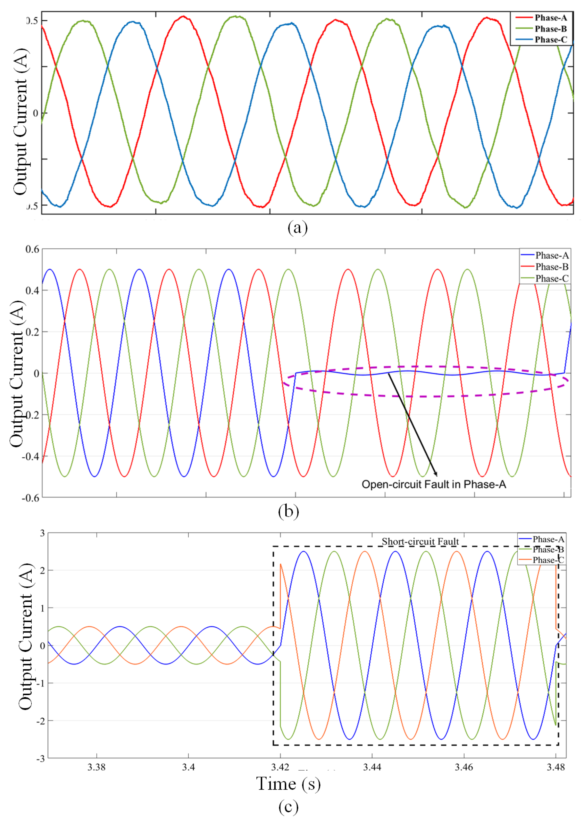
The objective of this case study is to verify the operation of the proposed system under normal operation. The output current waveform under the no-fault operation is shown in Figure 7a. Under normal operation, the two capacitors limit the voltage and current ripple on the inverter module to provide a sinusoidal output. The maximum capacitor voltage rating is equal to twice the peak voltage of the energy-storage device. There is no flow of discontinuous current through the inductors and capacitors. This results in continuous conduction mode (CCM) operation with a high reactive power. It can be inferred that the ZSI supplies a less distorted output current, as shown in Figure 7a, to the motor-pump arrangement.
4.2. Faulty Operation
The propagation of faults from faulty areas to normal areas results in damage to the system components. It may lead to a complete shutdown of the system. In an electrical system, transients are introduced in the event of a fault which should be avoided. In this part of the study, the variation in output current of the system under the switch failures due to open-circuit and short-circuit fault are presented.
4.2.1. Case 1: Open-Circuit Switch Fault
An open-circuit fault occurs due to the thermal cycling. For the simulation studies, the open-circuit fault is implemented in the IGBTs of phase-A. An open-circuit fault is created by turning off the gate signal of the power semiconductor switch. The output current waveform during this fault is shown in Figure 7b. It is observed that due to the switch failures occurred due to open-circuit fault, the corresponding phase current is zero.
4.2.2. Case 2: Short-Circuit Switch Fault
An IGBT short-circuit fault may occur due to high/wrong gate voltage, due to driver circuit failure, power supply failure or due to disturbance, and temperature rise or overvoltage stress. Short-circuit faults are difficult to deal with, as the time interval between the fault occurrence and diagnosis is very small. The faulty mode induces a nonzero dc component current in the stator winding. This results in dynamic braking of the motor drive. There are high chances of device failures in this faulty condition. The motor drive is not suitable to operate in this condition. The output current waveform is shown in Figure 7c. It can be seen from Figure 7c that there is an high rise in the output current across the faulty phase. This high current will damage the circuit components and hence is required to be prevented from flowing in the system.
4.2.3. Case 3: Motor Performance
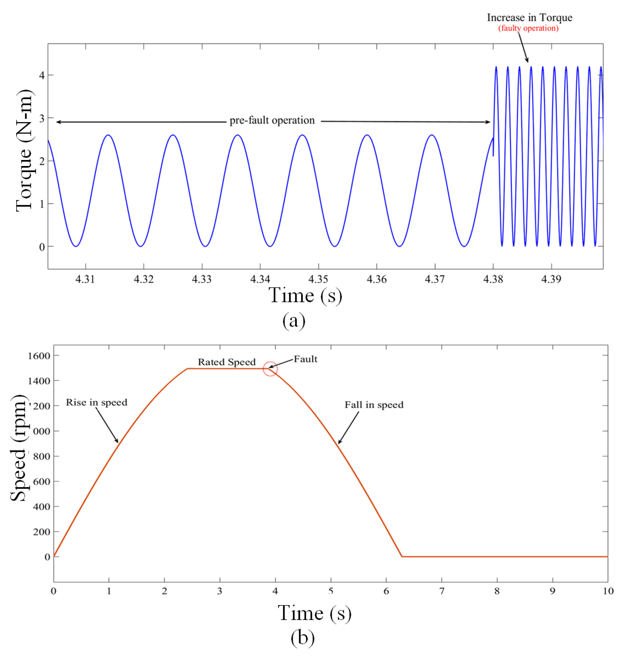
The motor-pump arrangement is the essential part of the irrigation application. The performance of the motor is required to be investigated under faulty operation to show the adverse effects of switch failure in the given system. In this aspect, the variations in torque and speed of the motor are studied. It can be observed from Figure 8a that under the faulty operation, the electromagnetic torque is increased due to the fault. The torque tends to show oscillations with high magnitudes which can lead to torsional vibrations and shaft failures. The operation of the motor drive is not suitable in such condition. In addition to it, there is a sudden fall in speed of the motor due to fault and hence motor eventually stops as shown in Figure 8b.
From the above analyses, it is clear that the conventional system without fault-tolerant capability is not suitable for irrigation application.
4.3. Post-Fault Operation
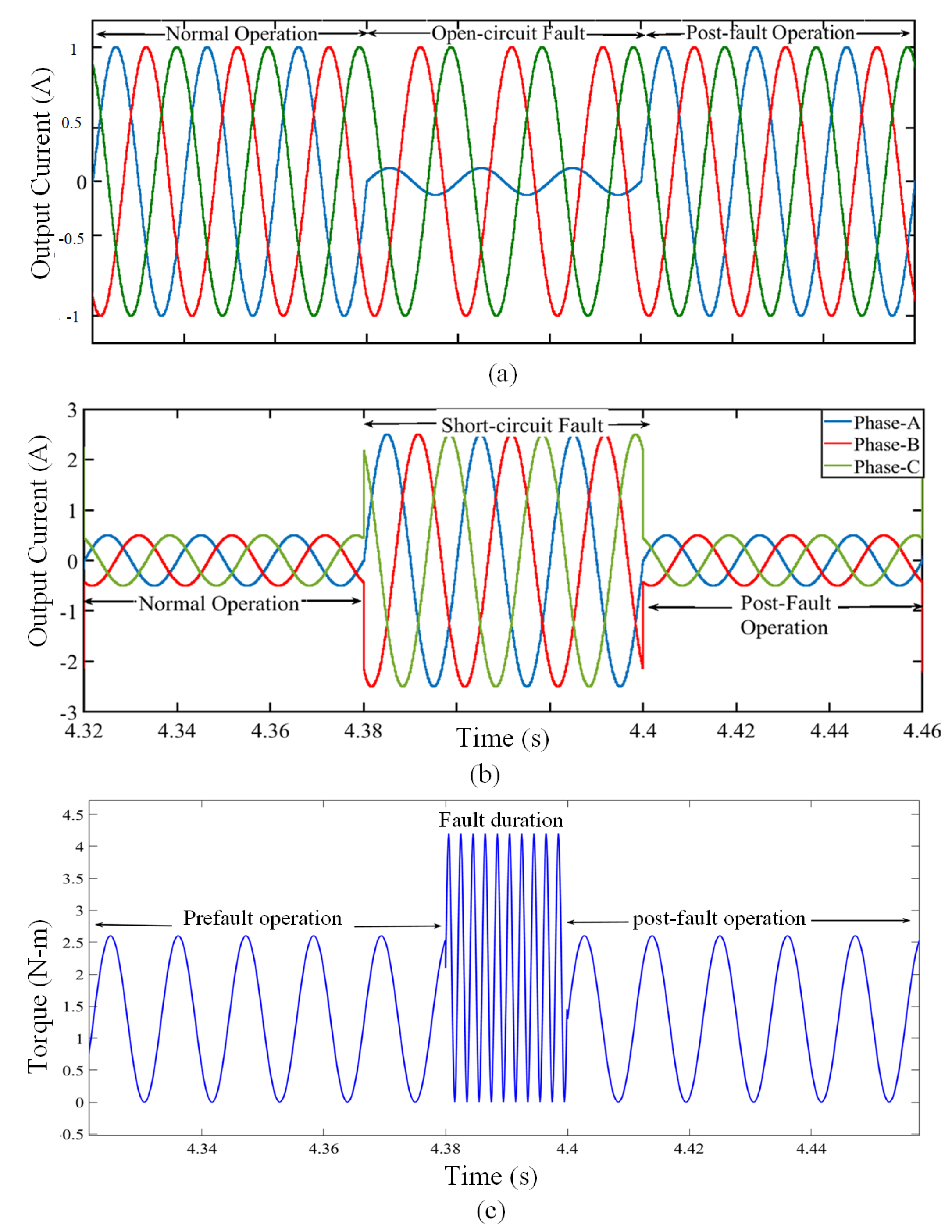
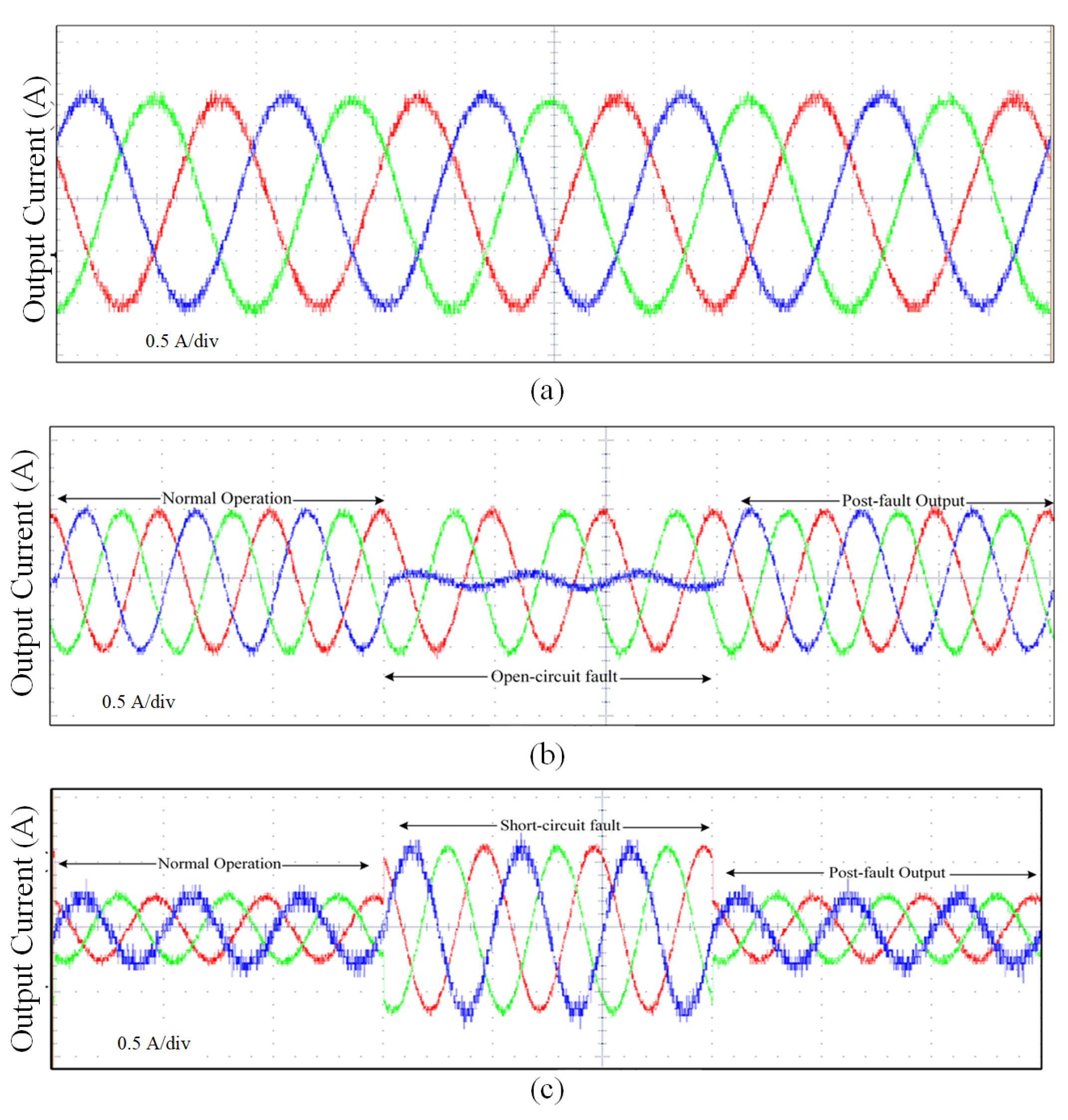
Based on the above analysis, it is recommended to implement an efficient fault-tolerant strategy in order to prevent propagation of the faults in the system. The output current waveform for the fault-tolerant control (FTC) operation under open-circuit fault and short-circuit are shown in Figure 9. The fault-tolerant operation is shown with a series of events; (i) pre-fault operation, (ii) faulty operation and (iii) post-fault operation after the implementation of the proposed fault-tolerant strategy.
It can be clearly seen in Figure 9a,b that the faults are introduced at t = 4.38 s and due to proposed fault-tolerant strategy the faults are cleared at an interval of 20 ms. Upon implementation of fault-tolerant strategy, the output current characteristics are identical to pre-fault condition. Moreover, the torque is restored back to the nominal value by utilizing the proposed fault-tolerant scheme. It can be observed in Figure 9c that torque increases for the fault duration and restores back to the rated value during fault-tolerant operation. The diagnosis time can be reduced by changing the switching sequence of the redundant circuit.
The main advantage of using the redundant configuration for the proposed system is that the system is able to maintain the dc-link voltage balance under normal and faulty conditions. Due to the proposed strategy, the output current waveform is ripple-free. The post-fault current and torque characteristics are identical to the normal operation characteristics. Moreover, the flyback effect is taken into consideration while implementing the switching sequence. This improves the reliability factor of the proposed technique for the motor-drive system. The primary goal of utilizing every voltage output of the source is fulfilled in this fault-tolerant strategy in order to provide the maximum output to the motor drive for irrigation applications.
5. Experimental Results
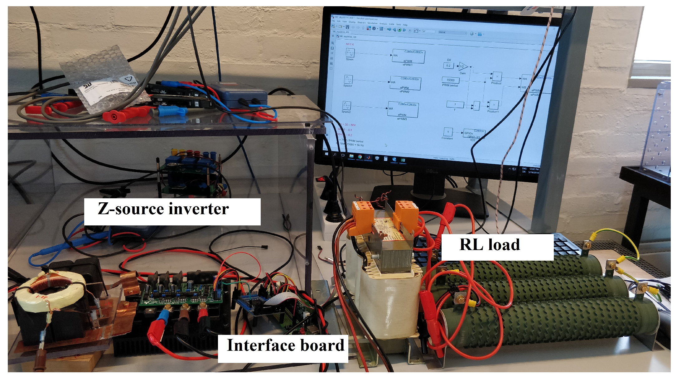
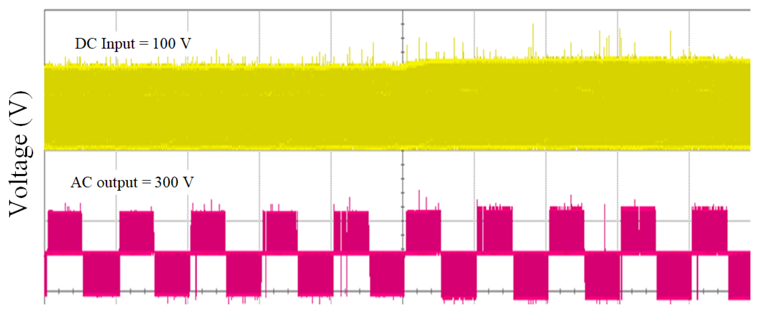
A laboratory prototype has been realized for the implementation of the proposed drive system under normal, faulty and fault-tolerant operation in this section. The experiments are conducted on a 1kW motor test bed, as shown in Figure 10, in order to validate the theoretical analysis and signify the performance of the proposed fault diagnosis algorithm. The test bench is operated at an input voltage of 100 V and output voltage of 300 V. The fault injection and control algorithm are interfaced through dSPACE control desk software. The fault incidents are manually injected in the drive system. The faults are introduced in phase-A IGBTs of the inverter module for the experimental studies.
5.1. Normal Operation
The output current waveform during normal operation of the proposed system are shown in Figure 11a. It can be seen that ripple-free waveforms are obtained across the three-phase winding of the motor. It depicts the continuous conduction mode of the proposed system.
5.2. Fault-Tolerant Operation
The output current response of the proposed system is observed for the fault-tolerant operation. To study the faulty conditions, fault-injection is done in the IGBTs of phase-A of the inverter module. The output current waveforms during pre-fault, faulty and post-fault operation are shown in Figure 11b,c. It is observed in Figure 11b that due to the open-circuit fault, the output current of the faulty phase-A is nearly zero. Once the fault-tolerant control is applied, the load current restores back the motor operation in due time. To investigate the short-circuit fault, the switches in the experimental setup are kept in ON-state for an infinite period. The output current waveform during pre-fault, faulty and post-fault operation for the short-circuit fault are shown in Figure 11c. It is observed that the proposed system restores to the normal operation after diagnosing the fault. The proposed control scheme provided service continuity at full power in event of faults. The experimental results are similar to the simulation results and confirms the validity of the proposed fault-tolerant strategy for the proposed system.
6. Compatibility of Proposed System for Irrigation Application
The achieved performance, detailed in Section 4 and Section 5, show that the proposed system has efficient fault-tolerance capability under switch failures. It is due to the better compensation strategies implemented under faulty operation. However, the compatibility of the proposed system is required to be investigated for the irrigation application. In view of this, the proposed system is analysed for three important factors [42,43,44,45]. Firstly, the voltage gain of proposed converter topology is required to be investigated. Secondly, as an essential component for irrigation, the operation of motor is to be regulated in such a way that an optimized system efficiency is achieved without any transients. Thirdly, the motor should exhibit better torque-speed characteristics. In this regard, the characteristics of the proposed system are demonstrated as follows:
6.1. Voltage Gain
There is a constant and intense demand for reliable, efficient, and small size step-up dc-dc converter in irrigation applications. To cater this issue, the proposed converter had shown continuous input current under variable load conditions. The voltage gain of the proposed converter is high enough to correspond with continuous high voltage applications. The voltage gain by proposed converter-inverter module is 3, as shown in Figure 12. It is inferred that the proposed Z-source network configuration provides a high boosting capability. It can also operate with variable and low duty cycle, which simplifies the design procedure and improves the performance. All of the mentioned features made the proposed converter topology a good candidate for irrigation application.
6.2. Harmonic Response
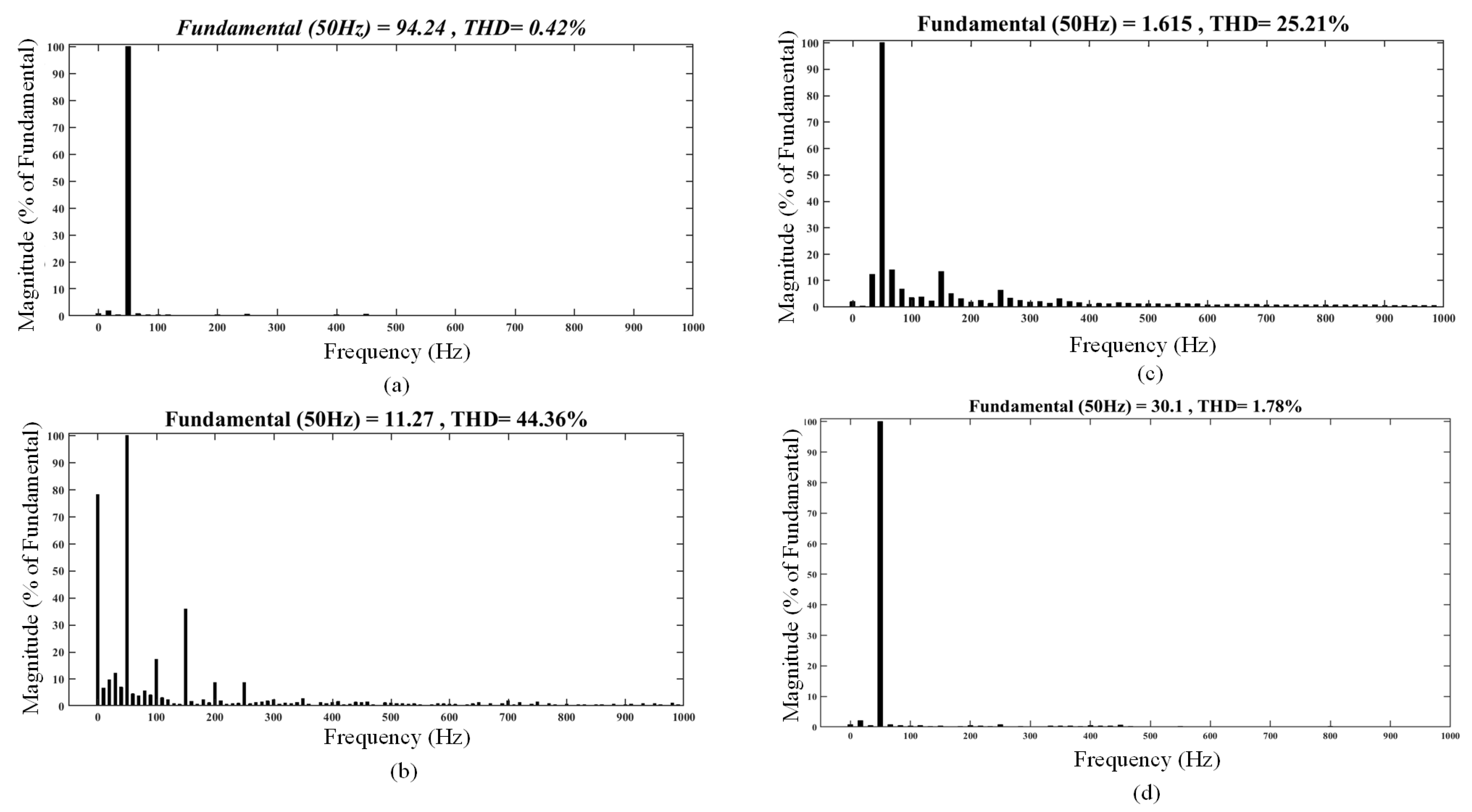
The efficient response of the proposed system towards transients is indicated by the percentage ripple of the output current supplied to the motor drive. The harmonic spectrum under normal operation is shown in Figure 13a. It is observed that under normal operation the total harmonic distortion (THD) is 0.42% with a high magnitude of the fundamental component.
Due to faults, the harmonic distortions are also introduced in the system. These distortions results in high ripples in the load current. Open-circuit faults induce a dc current offset in both normal and faulty phases. This offset current results in a pulsating torque at the stator current and hence in a reduction of the average torque for the drive. Additionally, transients are introduced in the system which deteriorate the power quality of the load current. The harmonic spectrum during this fault is shown in Figure 13b. It can be seen that the THD in case of the open-circuit fault is significantly high, with a magnitude of 44.36%.
The short-circuit currents creates unbalancing in the all phases. The transient response during such fault shows that the load current waveform is highly distorted. The harmonic spectrum during this fault is shown in Figure 13c. The THD in case of a short-circuit fault is significantly high, with magnitude of 25.21%.
Nevertheless, with the proposed fault-tolerant control method, the harmonic spectrum is close to the value that of normal operation. It can be seen in Figure 13d that the THD in case of FTC operation is negligible, with magnitude of 1.78%.
Similarly, the harmonic spectrum results under experimental analysis are determined for the load current of the given system under fault-tolerant operation. The observations of THD for simulation and experimental analysis are listed in Table 5.
It is worth highlighting from Table 5 that the total harmonic distortions values obtained with the proposed fault-tolerant operation are within the permissible standards IEEE 519-2014 and proves that this method is suitable in terms of power quality to implement for the motor drives for irrigation application.
6.3. Motor Performance
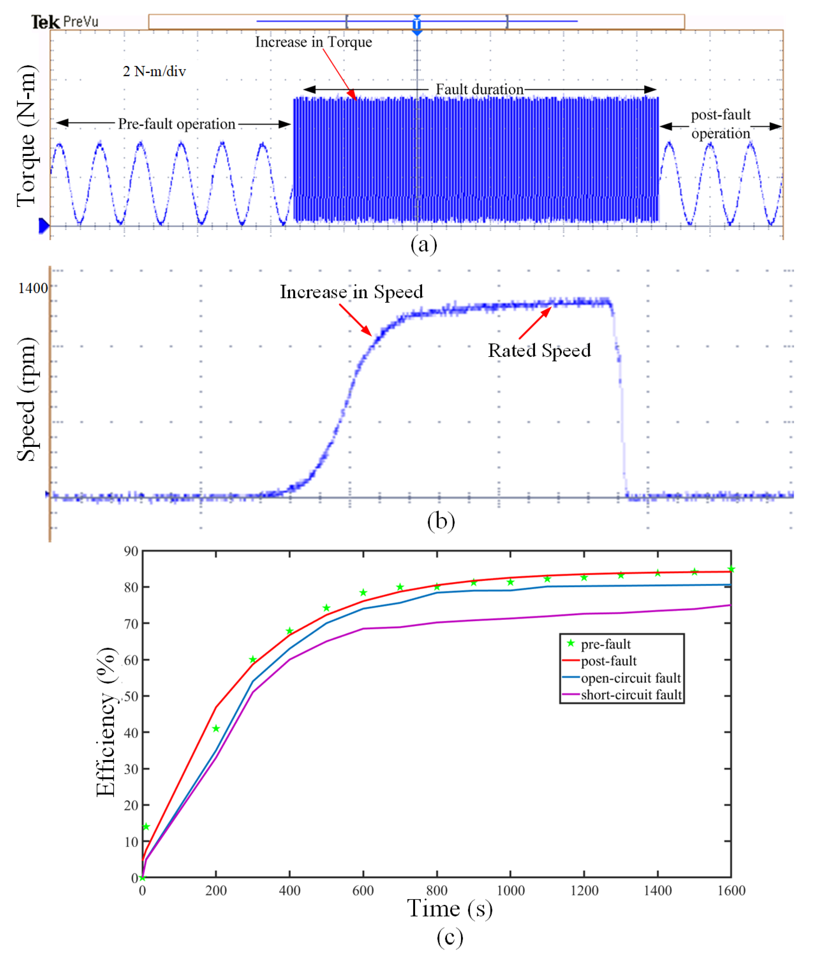
The achieved results demonstrated that the converter topology and FTC operation can compensate the current and torque with high power quality which results in improved the drive performance in fault conditions. The obtained results shows that the motor performance maintains a similar operation in pre-fault and post-fault operation upon implementation of the proposed fault-tolerant scheme. Moreover, the rated torque is restored back to the normal value during post-fault operation as shown in Figure 14a. Similarly, the motor speed, as shown in Figure 14b, gradually increases and reaches to the rated value with no fluctuations under FTC operation. The achieved torque-speed characteristics are suitable for irrigation application requiring constant speed operation under variable-load condition.
In addition to it, the motor efficiency is analysed in this section and shown in Figure 14c to validate the characteristics obtained during the prefault and post-fault operation. It can be observed that the motor efficiency is significantly reduced during open-circuit and short-circuit faults. However, due to the proposed FTC method the motor efficiency during post fault operation is maintained nearly equal to value of no-fault operation of the drive. The proposed drive system with fault-tolerant capability has exhibited an ability to operate at constant power over a wide speed range with excellent overall performance, and high efficiency.
The achieved results show that the system is suitable for the application of the motor-pump arrangement for rural irrigation and is less prone to shutdown with switch failures.
7. Conclusions
In this paper, the implementation of a PV-and ZSI-fed motor drive system with fault-tolerant capability for rural irrigation is designed and implemented. The proposed modulation scheme for Z-source inverter enables it to obtain a high voltage gain with a minimum component requirement. Additionally, a suitably fast and efficient fault-tolerant scheme is presented for the proposed system. It operates continuously without reduced output power and can be applied for all kinds of motor-drive applications. The reliability of the proposed topology is validated by simulation and experimental results. The proposed control scheme can eliminate the harmonic distortion issues related to the load current during the faulty operation. The motor performance parameters such as torque, speed, harmonic spectrum, and efficiency curve are presented to prove the system’s compatibility for irrigation application. The proposed system with a fault-tolerant capability proves to be an efficient and economical solution to the irrigation problems of the rural areas in developing countries.
Author Contributions
V.S. conceived, designed and performed the simulation and experimental evaluations and was responsible for preparing the original draft of this paper; M.J.H. supervised for the development of the power topology and conceptual solution and is responsible for reviewing and editing of this paper; S.M.N.A. and M.K. were responsible for the guidance towards relevant key theoretical and technical suggestions. All authors have read and agreed to the published version of the manuscript.
Funding
This research received no external funding. This research is carried under the International Research Training Program Scholarship (iRTP)-MQ45021783 granted by the Commonwealth of Australia.
Conflicts of Interest
The authors declare no conflict of interest.
Abbreviations
The following abbreviations are used in this manuscript:
| PWM | Pulse width modulation |
| IGBT | Insulated gate bipolar transistor |
| THD | Total harmonic distortion |
| PV | Photo-voltaic |
| ZSI | Impedance source inverter |
| VSI | Voltage source inverter |
| FTC | Fault-tolerant Control |
| CCM | Continuous conduction mode |
| IC | Integrated Circuit |
| MPP | Maximum Power Point |
References
- Coelho, B.; Andrade-Campos, A. Efficiency achievement in water supply systems—A review. Renew. Sustain. Energy Rev. 2014, 30, 59–84. [Google Scholar] [CrossRef]
- Kavya Santhoshi, B.; Mohana Sundaram, K.; Padmanaban, S.; Holm-Nielsen, J.B.; KK, P. Critical Review of PV Grid-Tied Inverters. Energies 2019, 12, 1921. [Google Scholar] [CrossRef] [Green Version]
- Ahmed, T.; Soon, T.; Mekhilef, S. A Single Phase Doubly Grounded Semi-Z-Source Inverter for Photovoltaic (PV) Systems with Maximum Power Point Tracking (MPPT). Energies 2014, 7, 3618–3641. [Google Scholar] [CrossRef] [Green Version]
- Sharma, V.; Panwar, C. Comparative analysis of PV FED DC-DC converters. In Proceedings of the 2014 International Conference on Green Computing Communication and Electrical Engineering (ICGCCEE), Coimbatore, India, 6–8 March 2014; pp. 1–4. [Google Scholar] [CrossRef]
- Peng, F.Z. Z-source inverter. IEEE Trans. Ind. Appl. 2003, 39, 504–510. [Google Scholar] [CrossRef]
- Cao, D.; Jiang, S.; Yu, X.; Peng, F.Z. Low-Cost Semi-Z-source Inverter for Single-Phase Photovoltaic Systems. IEEE Trans. Power Electron. 2011, 26, 3514–3523. [Google Scholar] [CrossRef]
- Peng, F.Z.; Joseph, A.; Wang, J.; Shen, M.; Chen, L.; Pan, Z.; Ortiz-Rivera, E.; Huang, Y. Z-source inverter for motor drives. IEEE Trans. Power Electron. 2005, 20, 857–863. [Google Scholar] [CrossRef]
- Hossameldin, A.A.; Abdelsalam, A.K.; Ibrahim, A.A.; Williams, B.W. Enhanced Performance Modified Discontinuous PWM Technique for Three-Phase Z-Source Inverter. Energies 2020, 13, 578. [Google Scholar] [CrossRef] [Green Version]
- Chen, X.; Fu, Q.; Infield, D.G. PV grid-connected power conditioning system with Z-source network. In Proceedings of the 2009 International Conference on Sustainable Power Generation and Supply, Nanjing, China, 6–7 April 2009; pp. 1–6. [Google Scholar] [CrossRef]
- Sun, D.; Ge, B.; Yan, X.; Bi, D.; Zhang, H.; Liu, Y.; Abu-Rub, H.; Ben-Brahim, L.; Peng, F.Z. Modeling, Impedance Design, and Efficiency Analysis of Quasi- Z Source Module in Cascaded Multilevel Photovoltaic Power System. IEEE Trans. Ind. Electron. 2014, 61, 6108–6117. [Google Scholar] [CrossRef]
- Belila, A.; Berkouk, E.M.; Benbouzid, M.; Amirat, Y.; Tabbache, B.; Mamoune, A. Control methodology and implementation of a Z-source inverter for a stand-alone photovoltaic-diesel generator-energy storage system microgrid. Electr. Power Syst. Res. 2020, 185, 106385. [Google Scholar] [CrossRef]
- Douida, S.; Tabbache, B.; Benbouzid, M. Direct Torque Control Based on Shoot-Through States of an Induction Motor Fed by a Z-Source Three-Level Neutral Point Clamped Inverter. IETE J. Res. 2019, 1–9. [Google Scholar] [CrossRef]
- Sharma, V.; Mukhopadhyay, S.; Hossain, M.J.; Nawazish Ali, S.M.; Kashif, M. A-source Inverter-fed PMSM drive with fault-tolerant capability for Electric Vehicles. In Proceedings of the 2020 IEEE 29th International Symposium on Industrial Electronics (ISIE), Kyoto, Japan, 20–23 June 2020; pp. 241–246. [Google Scholar]
- Sharma, V.; Hossain, M.J.; Ali, S.M.N.; Kashif, M.; Fernandez, E. Design and Implementation of Trans-Z-Source Inverter-Fed Induction Motor Drive with Fault-Tolerant Capability. In Proceedings of the 2020 IEEE Applied Power Electronics Conference and Exposition (APEC), New Orleans, LA, USA, 15–19 March 2020; pp. 690–695. [Google Scholar]
- Negi, B.; Sharma, V.; Bhatt, A.; Yadav, P. Effect of Faults on Power Electronic Devices for ZSI-Fed Induction Motor Drive System. In Proceeding of International Conference on Intelligent Communication, Control and Devices; Singh, R., Choudhury, S., Eds.; Springer: Singapore, 2017; pp. 747–752. [Google Scholar]
- de Araujo Ribeiro, R.L.; Jacobina, C.B.; da Silva, E.R.C.; Lima, A.M.N. Fault-tolerant voltage-fed PWM inverter AC motor drive systems. IEEE Trans. Ind. Electron. 2004, 51, 439–446. [Google Scholar] [CrossRef]
- Farhadi, M.; Fard, M.T.; Abapour, M.; Hagh, M.T. DC–AC Converter-Fed Induction Motor Drive with Fault-Tolerant Capability under Open- and Short-Circuit Switch Failures. IEEE Trans. Power Electron. 2018, 33, 1609–1621. [Google Scholar] [CrossRef] [Green Version]
- Karimi, S.; Poure, P.; Saadate, S. Fast power switch failure detection for fault tolerant voltage source inverters using FPGA. IET Power Electron. 2009, 2, 346–354. [Google Scholar] [CrossRef]
- Tousizadeh, M.; Che, H.S.; Selvaraj, J.; Rahim, N.A.; Ooi, B. Performance Comparison of Fault-Tolerant Three-Phase Induction Motor Drives Considering Current and Voltage Limits. IEEE Trans. Ind. Electron. 2019, 66, 2639–2648. [Google Scholar] [CrossRef]
- Jiang, X.; Xu, D.; Gu, L.; Li, Q.; Xu, B.; Li, Y. Short-Circuit Fault-Tolerant Operation of Dual-Winding Permanent-Magnet Motor under the Four-Quadrant Condition. IEEE Trans. Ind. Electron. 2019, 66, 6789–6798. [Google Scholar] [CrossRef]
- Tousizadeh, M.; Che, H.S.; Selvaraj, J.; Rahim, N.A.; Ooi, B. Fault-Tolerant Field-Oriented Control of Three-Phase Induction Motor Based on Unified Feedforward Method. IEEE Trans. Power Electron. 2019, 34, 7172–7183. [Google Scholar] [CrossRef]
- Beltrao de Rossiter Correa, M.; Brandao Jacobina, C.; Cabral da Silva, E.R.; Nogueira Lima, A.M. An induction motor drive system with improved fault tolerance. IEEE Trans. Ind. Appl. 2001, 37, 873–879. [Google Scholar] [CrossRef]
- Kastha, D.; Bose, B.K. Investigation of fault modes of voltage-fed inverter system for induction motor drive. IEEE Trans. Ind. Appl. 1994, 30, 1028–1038. [Google Scholar] [CrossRef]
- Li, Q.; Jiang, X.; Huang, W.; Cao, R. Fault-tolerant drive system based on the redundancy bridge arm for aerospace applications. IET Electric Power Appl. 2018, 12, 780–786. [Google Scholar] [CrossRef]
- Zhang, J.; Zhang, Z.; Yu, L.; Bian, Z. Fault-tolerant control of DSBLDC motor drive under open-circuit faults. IET Electr. Power Appl. 2019, 13, 494–502. [Google Scholar] [CrossRef]
- Han, G.; Chen, H.; Shi, X. Modelling, diagnosis, and tolerant control of phase-to-phase fault in switched reluctance machine. IET Electric Power Appl. 2017, 11, 1527–1537. [Google Scholar] [CrossRef]
- Wang, B.; Li, Z.; Bai, Z.; Krein, P.T.; Ma, H. A Redundant Unit to Form T-Type Three-Level Inverters Tolerant of IGBT Open-Circuit Faults in Multiple Legs. IEEE Trans. Power Electron. 2020, 35, 924–939. [Google Scholar] [CrossRef]
- Zhang, J.; Zhan, W.; Ehsani, M. Fault-Tolerant Control of PMSM with Inter-Turn Short-Circuit Fault. IEEE Trans. Energy Conver. 2019, 34, 2267–2275. [Google Scholar] [CrossRef]
- Zhang, W.; Xu, D.; Enjeti, P.N.; Li, H.; Hawke, J.T.; Krishnamoorthy, H.S. Survey on Fault-Tolerant Techniques for Power Electronic Converters. IEEE Trans. Power Electron. 2014, 29, 6319–6331. [Google Scholar] [CrossRef]
- Mirafzal, B. Survey of Fault-Tolerance Techniques for Three-Phase Voltage Source Inverters. IEEE Trans. Ind. Electron. 2014, 61, 5192–5202. [Google Scholar] [CrossRef]
- Li, S.; Xu, L. Strategies of fault tolerant operation for three-level PWM inverters. IEEE Trans. Power Electron. 2006, 21, 933–940. [Google Scholar] [CrossRef]
- Campos-Delgado, D.U.; Espinoza-Trejo, D.R.; Palacios, E. Fault-tolerant control in variable speed drives: A survey. IET Electr. Power Appl. 2008, 2, 121–134. [Google Scholar] [CrossRef]
- Pillai, D.S.; Blaabjerg, F.; Rajasekar, N. A Comparative Evaluation of Advanced Fault Detection Approaches for PV Systems. IEEE J. Photovoltaics 2019, 9, 513–527. [Google Scholar] [CrossRef]
- Saied, M.M.; Hanafy, A.A.; El-Gabaly, M.A.; Safar, Y.A.; Jaboori, M.G.; Yamin, K.A.; Sharaf, A.M. Optimal design parameters for a PV array coupled to a DC motor via a DC-DC transformer. IEEE Trans. Energy Conv. 1991, 6, 593–598. [Google Scholar] [CrossRef]
- Villalva, M.G.; Siqueira, T.G.D.; Ruppert, E. Voltage regulation of photovoltaic arrays: Small-signal analysis and control design. IET Power Electron. 2010, 3, 869–880. [Google Scholar] [CrossRef]
- Yang, B.; Li, W.; Zhao, Y.; He, X. Design and Analysis of a Grid-Connected Photovoltaic Power System. IEEE Trans. Power Electron. 2010, 25, 992–1000. [Google Scholar] [CrossRef]
- Hosseinzadeh, M.; Rajaei Salmasi, F. Determination of maximum solar power under shading and converter faults—A prerequisite for failure-tolerant power management systems. Simul. Model. Pract. Theory 2016, 62, 14–30. [Google Scholar] [CrossRef]
- Huang, Y.; Shen, M.; Peng, F.Z.; Wang, J. Z-Source Inverter for Residential Photovoltaic Systems. IEEE Trans. Power Electron. 2006, 21, 1776–1782. [Google Scholar] [CrossRef]
- Lu, B.; Sharma, S.K. A Literature Review of IGBT Fault Diagnostic and Protection Methods for Power Inverters. IEEE Trans. Ind. Appl. 2009, 45, 1770–1777. [Google Scholar] [CrossRef]
- Chahmi, A.; Bendjebbar, M.; Raison, B. Fault detection In electrical drives-approach signal. In Proceedings of the 2014 International Conference on Electrical Sciences and Technologies in Maghreb (CISTEM), Tunis, Tunisia, 3–6 November 2014; pp. 1–6. [Google Scholar] [CrossRef] [Green Version]
- Rodríguez-Blanco, M.A.; Vázquez-Pérez, A.; Hernández-González, L.; Golikov, V.; Aguayo-Alquicira, J.; May-Alarcón, M. Fault Detection for IGBT Using Adaptive Thresholds during the Turn-on Transient. IEEE Trans. Ind. Electron. 2015, 62, 1975–1983. [Google Scholar] [CrossRef]
- Tomar, A.; Mishra, S.; Bhende, C.N. AOMH–MISO Based PV–VCI Irrigation System Using ASCIM Pump. IEEE Trans. Ind. Appl. 2018, 54, 4813–4824. [Google Scholar] [CrossRef]
- Varshney, A.; Sharma, U.; Singh, B. Self-regulated DC-link control of synchronous reluctance motor-driven solar water pumping system. IET Power Electron. 2019, 12, 3220–3230. [Google Scholar] [CrossRef]
- Kumar, R.; Singh, B. Solar PV powered BLDC motor drive for water pumping using Cuk converter. IET Electr. Power Appl. 2017, 11, 222–232. [Google Scholar] [CrossRef]
- Koreboina, V.B.; Narasimharaju, B.L.; Vinod Kumar, D.M. Performance investigation of simplified PWM MPPT approach for direct PV-fed switched reluctance motor in water pumping system. IET Electr. Power Appl. 2017, 11, 1645–1655. [Google Scholar] [CrossRef]
Figure 1.
Circuit diagram of the photovoltaic (PV)-fed Impedance (Z)-source inverter (ZSI)-fed motor drive for pumping application.
Figure 1.
Circuit diagram of the photovoltaic (PV)-fed Impedance (Z)-source inverter (ZSI)-fed motor drive for pumping application.

Figure 2.
Proposed modulation scheme.

Figure 3.
Proposed fault-tolerant strategy.

Figure 4.
Short-circuit fault detection circuit.

Figure 5.
Control scheme of the proposed fault-tolerant strategy.

Figure 6.
Flowchart of the proposed fault-tolerant strategy.

Figure 7.
Simulation results of output current: (a) Normal operation, (b) open-circuit fault, and (c) short-circuit fault.
Figure 7.
Simulation results of output current: (a) Normal operation, (b) open-circuit fault, and (c) short-circuit fault.

Figure 8.
Motor performance under faulty operation: (a) Torque response; (b) speed response.

Figure 9.
Simulation results under fault-tolerant control (FTC) operation: (a) Output current under open-circuit fault, (b) output current under short-circuit fault, and (c) torque response.
Figure 9.
Simulation results under fault-tolerant control (FTC) operation: (a) Output current under open-circuit fault, (b) output current under short-circuit fault, and (c) torque response.

Figure 10.
Experimental test bench.

Figure 11.
Experimental results: (a) Normal operation, (b) open-circuit fault, and (c) short-circuit fault.
Figure 11.
Experimental results: (a) Normal operation, (b) open-circuit fault, and (c) short-circuit fault.

Figure 12.
Voltage waveform of proposed converter-inverter topology.

Figure 13.
Harmonic spectrum: (a) Normal operation, (b) open-circuit fault, (c) short-circuit fault, and (d) FTC operation.
Figure 13.
Harmonic spectrum: (a) Normal operation, (b) open-circuit fault, (c) short-circuit fault, and (d) FTC operation.

Figure 14.
Motor performance under FTC operation: (a) Torque response, (b) speed response, and (c) efficiency curve.
Figure 14.
Motor performance under FTC operation: (a) Torque response, (b) speed response, and (c) efficiency curve.


Table 1.
Design parameters of Solar PV Array.
| Symbol | Description | Value |
|---|---|---|
| Open-circuit voltage of one module | 21.6 V | |
| Short-circuit current of one module | 0.64 A | |
| MPP voltage | 600 V | |
| MPP current | 14.5 A | |
| Number of series-connected modules | 34 | |
| Number of parallel-connected modules | 25 |
Table 2.
Parameters of Z-source network.
| Symbol | Description | Specification |
|---|---|---|
| M | Modulation Index | 0.72 |
| B | Boost factor | 1.92 |
| = | Inductance | 1.3 mH |
| = | Capacitance | 1000 F |
| D | Duty cycle | 0.5 |
| Carrier frequency | 10 kHz | |
| Shoot-through frequency | 20 kHz |
Table 3.
Motor Specifications.
| Symbol | Description | Specification |
|---|---|---|
| P | Number of poles | 6 |
| Power | 4 kW | |
| N | Speed | 1500 rpm |
| Stator Resistance | 0.6 | |
| Rotor Resistance | 0.6 | |
| J | Moment of Inertia | 0.05 kg·m |
| Mutual Inductance | 0.03 H |
Table 4.
Detection of faulty phase/switch.
| Faulty Switch | Slope | Current in Faulty Phase |
|---|---|---|
| 0 | - | |
| 0 | + | |
| - | ||
| + | ||
| - | ||
| + |
Table 5.
Harmonic spectrum results.
| Condition | Simulation Results | Experimental Results |
|---|---|---|
| Normal operation | 0.42 | 1.23 |
| Open-circuit fault | 44.36 | 41.23 |
| Short-circuit fault | 25.21 | 22.36 |
| Post-fault operation | 1.78 | 1.52 |
© 2020 by the authors. Licensee MDPI, Basel, Switzerland. This article is an open access article distributed under the terms and conditions of the Creative Commons Attribution (CC BY) license (http://creativecommons.org/licenses/by/4.0/).
Share and Cite
MDPI and ACS Style
Sharma, V.; Hossain, M.J.; Ali, S.M.N.; Kashif, M. A Photovoltaic-Fed Z-Source Inverter Motor Drive with Fault-Tolerant Capability for Rural Irrigation. Energies 2020, 13, 4630. https://doi.org/10.3390/en13184630
AMA Style
Sharma V, Hossain MJ, Ali SMN, Kashif M. A Photovoltaic-Fed Z-Source Inverter Motor Drive with Fault-Tolerant Capability for Rural Irrigation. Energies. 2020; 13(18):4630. https://doi.org/10.3390/en13184630
Chicago/Turabian StyleSharma, Vivek, M. J. Hossain, S. M. Nawazish Ali, and Muhammad Kashif. 2020. "A Photovoltaic-Fed Z-Source Inverter Motor Drive with Fault-Tolerant Capability for Rural Irrigation" Energies 13, no. 18: 4630. https://doi.org/10.3390/en13184630
Note that from the first issue of 2016, this journal uses article numbers instead of page numbers. See further details here.