Improved Direct Model Predictive Control for Grid-Connected Power Converters


1
Chair of Electrical Drive Systems and Power Electronics (EAL), Technische Universität München, 80333 München, Germany
2
Electrical Engineering Department, Faculty of Engineering, Assiut University, Assiut 71516, Egypt
3
Faculty of Engineering, University Andrés Bello, Santiago 8370146, Chile
*
Author to whom correspondence should be addressed.
Energies 2020, 13(10), 2597; https://doi.org/10.3390/en13102597
Submission received: 21 April 2020
/
Revised: 13 May 2020
/
Accepted: 15 May 2020
/
Published: 20 May 2020
(This article belongs to the Section F: Electrical Engineering)
Abstract
:This paper proposes a computationally efficient and robust direct model predictive control (DMPC) technique with enhanced steady-state performance for power converters tied to the electric utility. The discrete space vector modulation (DSVM) method is considered in the design of the suggested DMPC, where virtual voltage vectors (VVs) besides the real ones are utilized for improving the steady-state response of the proposed controller. Furthermore, for averting the high computational burden and making the proposed control technique simple, a deadbeat (DB) function is employed for calculating the reference VV based on the required reference current. Subsequently, a discrete-time integral term is combined with this DB function to enhance the robustness of the suggested DMPC technique against variations of the model parameters. Finally, the best virtual or real VV is chosen by a certain quality function, which will be applied to the power converter in the next sample. The suggested technique is verified by simulation results and its performance is compared with the classical DMPC and voltage-oriented control (VOC).
1. Introduction
Currently, renewable energy systems (wind, photovoltaic, wave, and others) are growing quickly because of the increasing demand for electrical power generation and the necessity to limit emissions of greenhouse gases from the traditional fossil-fuel based electric power generation plants [1,2,3]. In wind and photovoltaic energy generation systems connected to the grid, power converters are usually employed for current/voltage conversion from DC to AC and vice versa [4]. Commonly, the control system of those power converters is designed based on the voltage-oriented control (VOC) principles [5,6,7]. Accordingly, the control system is designed in the rotating reference frame utilizing proportional-integral (PI) regulators. Satisfactory transient and steady-state responses are the main features of those PI regulators. However, their linear natural and the limited bandwidth are the main drawbacks. In the last few years, several modern/advanced control schemes, such as fuzzy logic, model predictive control, and others, were proposed for grid-tied power converters [5,6,7,8,9,10,11,12,13,14].
Model predictive control (MPC) techniques are forceful and promising controllers for power converters and motor drive systems. The MPC schemes can be divided to three types: (1) deadbeat control (DBC) [15,16], (2) continuous-control-set MPC (CCSMPC) [17,18], and (3) direct MPC (DMPC) [9,10,11,12,13,14,19,20,21]. In DBC technique, the model of the system under control in discrete-time is employed to find the reference voltage (RV) that is necessary to track the reference power/current in the next sample. Then, a modulator is employed for applying this RV to the power converter. DBC is uncomplicated and its implementation is easy. However, due to the fact that DBC is designed by considering the system model, it is sensitive to variations of the model parameters. CCSMPC uses the discrete-model of the controlled-object to predict its future response over the prediction horizon. Subsequently, an optimization function is employed to obtain the superior voltage vector to apply by the modulator. In the design of the CCSMPC, it is effortless to include constraints/nonlinearities of the object under control. However, due to the high calculation burden of the CCSMPC, part of the control algorithm is usually implemented offline.
DMPC, also called finite-control-set MPC (FCS-MPC), considers the discrete-time model of the power converter and its limited-number of switching vectors for solving the optimization problem [9,10,11,12,13,14,19,20,21]. Accordingly, its calculation burden is remarkably smaller than the CCSMPC. Therefore, the whole algorithm of the DMPC is usually implemented online. Furthermore, it is uncomplicated to consider the constraints and nonlinearities of the system under control in the design of the DMPC. However, featured by its one voltage vector (VV) for each control interval, higher ripples were observed in the waveforms of the power/current, even with less sampling time than the traditional VOC technique with a modulation stage. This problem can be solved by increasing the sampling frequency (i.e., reducing the sampling time), which will make the ripples smaller; i.e., enhancing the response of DMPC in steady-state. However, this method is leading to the rise of hardware costs. Therefore, improving the steady-state response of the DMPC without reducing the sampling time is necessary and highly required.
In [22,23], a null vector along with an active vector are applied in each sampling period to enhance the response of the DMPC in steady-state for permanent-magnet synchronous machines (PMSMs) and grid-tied power converters. However, the ripples in the output current are still higher than the linear controllers; i.e., field-oriented control (FOC) and VOC. In order to solve this problem, multiple vector (two active voltage vectors (VVs) and a zero VV)-based MPC has been proposed in [24,25,26,27]. However, the computational load of the proposed algorithms is high. Furthermore, the concept of FCS-MPC is missed in those techniques [24,25,26,27]; i.e., an infinite number of VVs can be applied for the power converter. Furthermore, the proposed techniques in [22,23,24,25,26,27] and the traditional FCS-MPC are sensitive to uncertainties/mismatches in the parameters of the system model.
For reducing the sensitivity of the DMPC schemes to variations of the model parameters, online estimations of those parameters by several observers have been presented in the literature. Among these observers, least-square technique [28], extended Kalman filter [29,30], unscented Kalman filter [31], and finite-inductance-set observer [31] are preferred. However, the major drawback of these online observation techniques is the remarkably high calculation load. Another solution is the use of model-free predictive control (MFPC) techniques [32,33], where the measured currents are employed in the prediction model instead of the system model, and accordingly, the sensitivity to uncertainties/mismatches in the parameters of the system model is averted. However, MFPC schemes are highly based on the precision of the current measurement. Therefore, the controller may be lose its stability due to errors or noise in the measured currents. A common solution is observation of the total disturbance resulting from parameter variations and considering it in the controller design. Sliding-mode observer [34], time delay control approach [15], disturbance observers [35], and others [36] were presented to increase the robustness of DMPC methods to variations of the model parameters. However, the major weakness of all of those estimators is the high computational load.
In this paper, an effective DMPC with enhanced performance in both dynamic and steady-state is proposed. The suggested DMPC applies three voltage vectors (VVs) to the power converter in each sampling period by addition of virtual VVs to the real ones of the power converter, i.e., using the discrete space vector modulation (DSVM) technique. However, by addition of several virtual VVs, the number of iterations for current predictions and cost function evaluations is remarkably increased. Therefore, for reducing the computational load, a direct calculation of the reference voltage vector (VV) based on the reference currents is suggested; i.e., all the iterations required for current predictions are avoided. Furthermore, for improving the robustness of the suggested DMPC against uncertainties/mismatches in the parameters of the system model, a discrete time integral term, which is very simple (and its calculation load is very low) is added to the reference VV calculation. Subsequently, a set of six candidates, real and virtual VVs, are selected based on the location of the obtained reference VV. Accordingly, the cost function is evaluated only six times to obtain the optimal VV. In comparison to [22,23,24,25,26,27], the concept of the FCS-MPC is still applied in the proposed DMPC; i.e., a limited number of VVs are defined and the controller selects the optimal one in each sampling interval. The performance of the suggested DMPC technique is verified by simulation results and its performance is compared with the traditional FCS-MPC and the famous VOC.
The rest of this paper is organized as follows: the modeling of the grid-tied power converter is explained in Section 2. The VOC, traditional DMPC, and proposed robust DMPC with improved steady-state are detailed in Section 3, Section 4 and Section 5, respectively. The simulation results are given in Section 6 and the paper is concluded in Section 7.
2. Modeling of the Grid Connected Power Converter
In the system under study illustrated in Figure 1, a power converter is tied to the electric utility (grid) via the well-known passive RL filter with resistance and inductance , where and are the nominal values of the resistance/inductance and and are the variations in the resistance/inductance due to temperature, aging, saturation, etc. The model of the power converter can be expressed in different reference frames; i.e., three-phase , stationary , and rotating reference frames. However, usually the control system of the grid-tied power converters is implemented in the frame. Therefore, the model of the power converter in continuous-time is expressed as follows.
where , , , , , and are the axes’ elements of the grid voltage, output voltage of the power converter, and current, respectively. In (1), is the grid voltage angular speed. Finally, and are the total disturbances because of: (1) uncertainties/mismatches in the parameters of the system model, and (2) un-modeled dynamics of the system under control. These items are written as follows.
where and are the un-modeled uncertainties of the d and q axes, respectively. In the rotating reference frame, the output active P and reactive Q power are written as:
The DMPC utilizes the model of the power converter in discrete-time for predicting its performance in the future. The discrete-time model can be obtained by applying a discretization method such as the forward Euler technique to the continuous-time model in Equations (1) and (2). Accordingly, the discrete-time model of the power converter can be expressed as
3. Voltage-Oriented Control
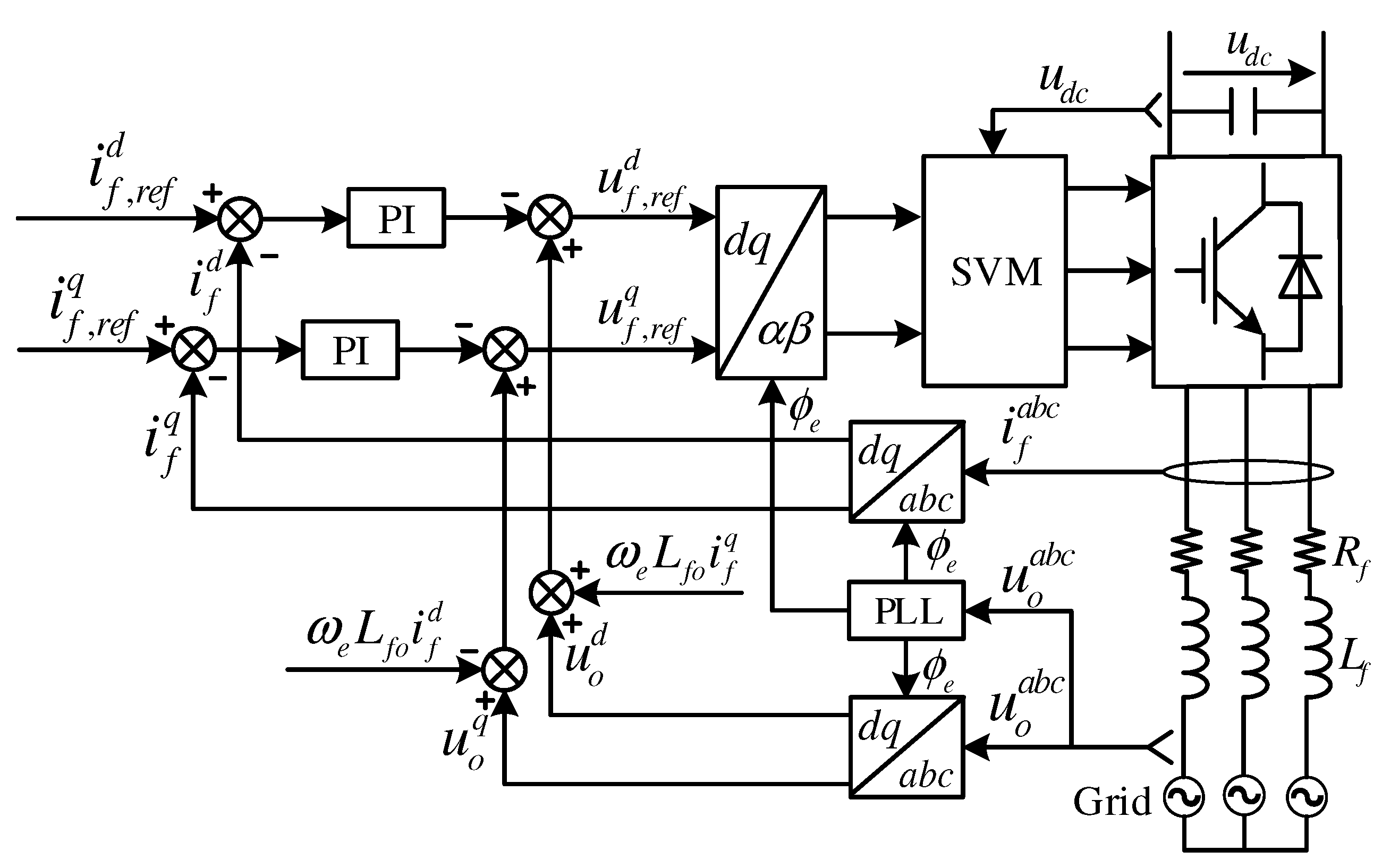
The voltage-oriented control (VOC) method with PI regulators is a famous controller for grid-connected power converters due to its constant switching frequency [5,6,7]. On one hand, this control strategy guarantees satisfactory transient/steady-state performances and is robust to uncertainties/mismatches in the parameters of the system model. On the other hand, its linearity and bounded bandwidth are the major cons of the VOC with PI regulators. Furthermore, inclusion of constrains and nonlinearities is not easy in the design of VOC.
In the rotating reference frame, the d-axis is aligned with the voltage vector of the electric utility. Accordingly, and . By using this fact, Equation (3) is simplified as:
According to Equation (6), the regulation of the active P and reactive Q power can be realized by the d and q-axis currents as follows:
where and are the real and imaginary reference power, respectively. In Equation (7), and are the reference currents of the d and q-axis, respectively. These reference currents are compared with the actual measured ones , and the error signals of the d and q-axis are the inputs to the PI regulators; see Figure 1. The PI regulators give the reference VV , which is then expressed in the reference frame by using Park transformation. Finally, the switching signals of the power converter are produced by using the space vector modulation technique [37].
4. Traditional Direct-Model Predictive Control
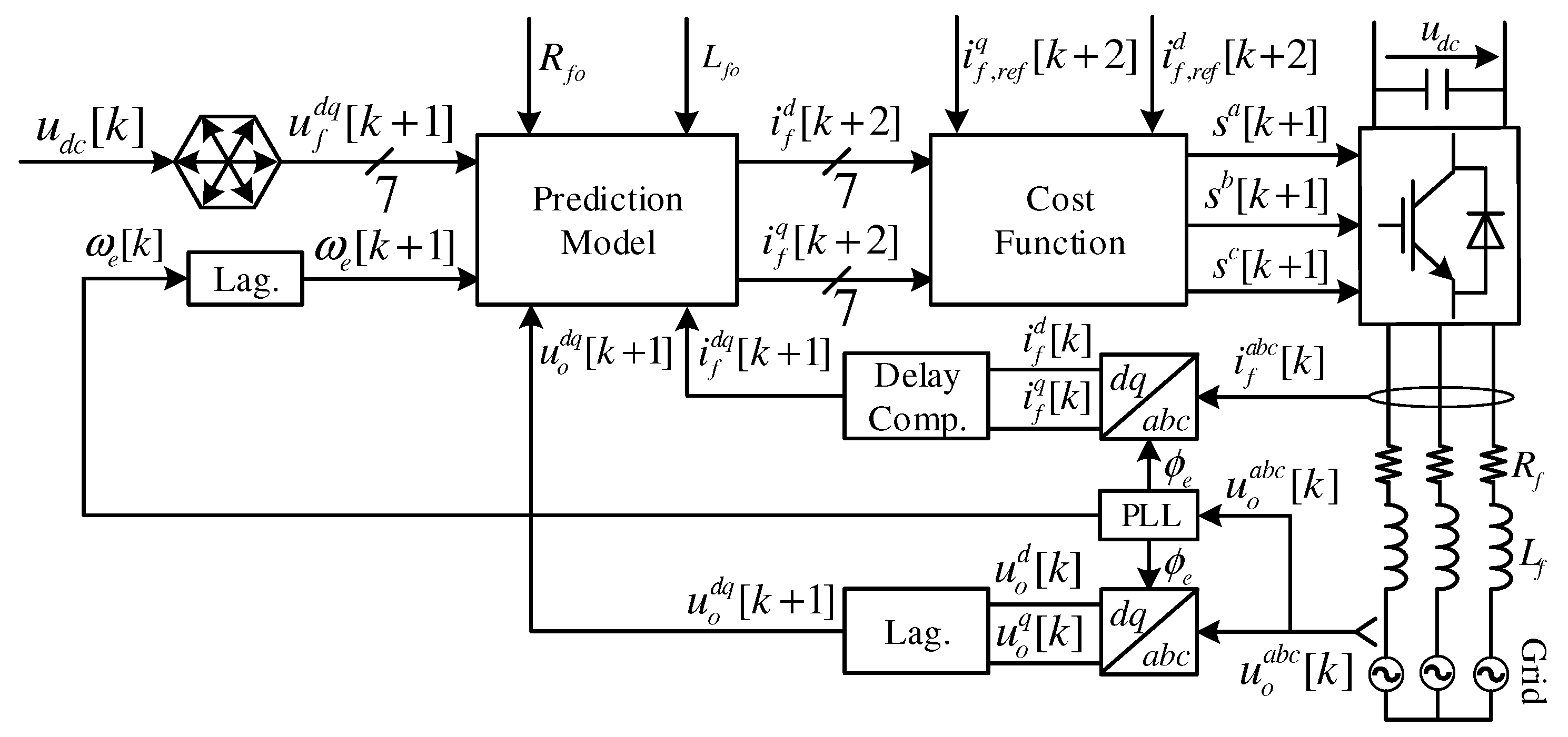
Based on the principles of the direct-model predictive control (DMPC), a fixed-number of switching actions of the power converter is utilized for predicting its future performance. Commonly, in the classical DMPC, the nominal parameters of the filter (i.e., and ) are taken into account in the prediction model. Accordingly, rearranging Equation (4), neglecting , and taking into account the delay (one-sample) because of the digital controller [15], the prediction model of the d and q-axis currents can be written as follows:
where is computed as follows
The angular speed and grid voltage are calculated by Lagrange extrapolation as follows:
In Equation (8), can be expressed as a function of the switching state vector of the power converter as follows.
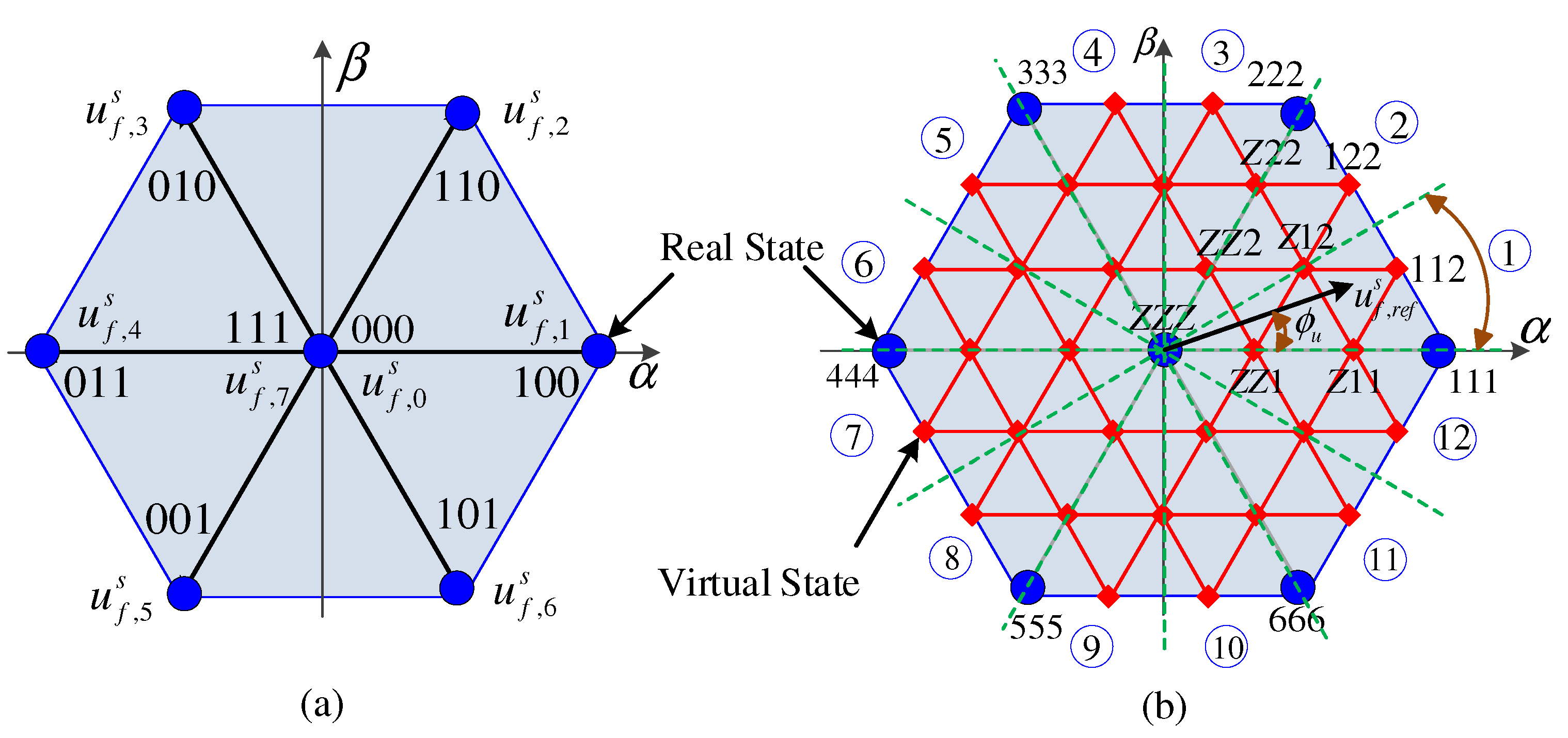
In Equation (11), and are the Park and Clarke transformation matrices, respectively. is the DC-link voltage and is the output voltages of the power converter in the reference frame. is the electrical position of the grid voltage. According to Figure 2a, seven different voltage vectors can be obtained from the eight switching states of the two-level power converter. Subsequently, seven values of the current and can be predicted by those seven voltage vectors. Finally, the cost function
is evaluated seven times to select the best voltage vector, which minimizes the error between the reference current and predicted one. In Equation (12), and are the reference currents of the & axis and they are obtained by using Lagrange extrapolation as follows.
In Equation (12), is the maximum allowed output current of the power converter. Figure 3 shows the schematic diagram of the traditional DMPC for grid-connected power converters.
It can be observed from Equations (8) and (9) that the traditional DMPC is strongly based on the parameters of the model of the system under control. Therefore, parameter mismatches will worsen the control performance. Moreover, in each sampling period, only one voltage vector is selected and applied to the power converter. Accordingly, high ripples in the output current/power will be produced. Finally, the high computational load is another disadvantage of the classical DMPC.
5. Proposed Direct-Model Predictive Control
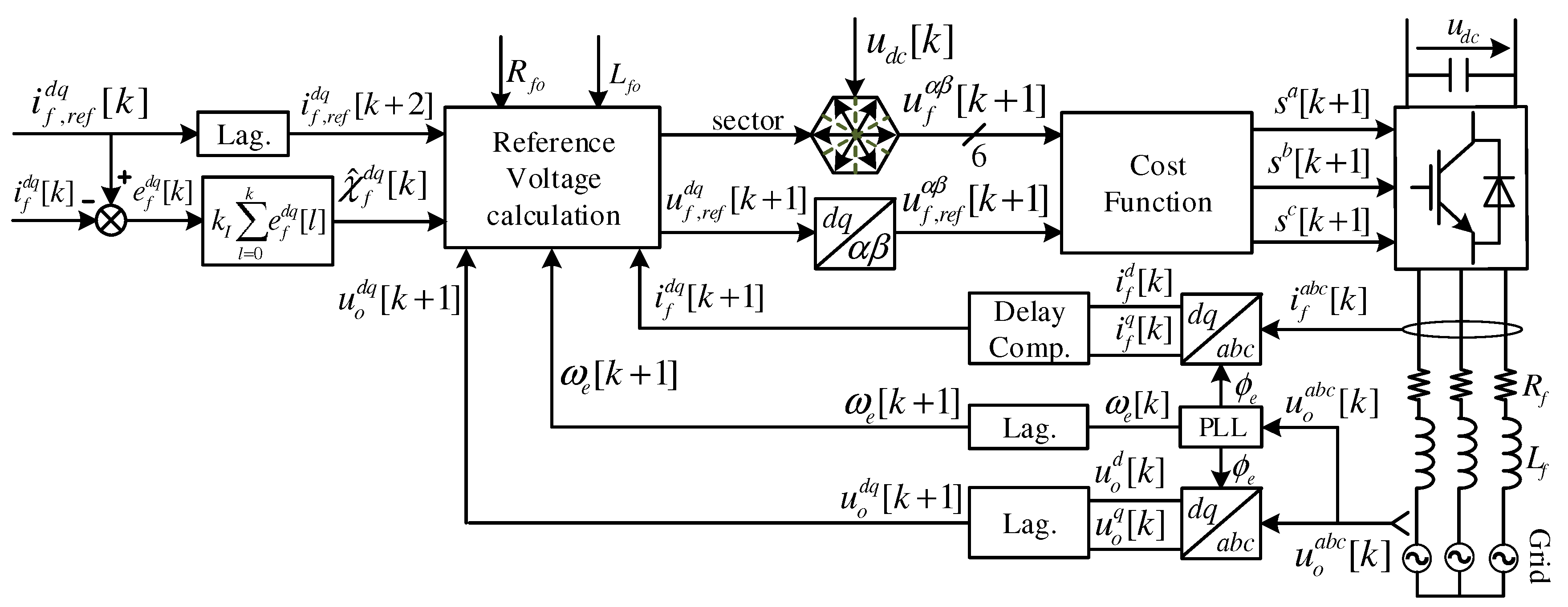
For reducing the ripples of the traditional DMPC in the output current and power, virtual voltage vectors are added to the seven real ones, as illustrated in Figure 2b. Therefore, if a virtual (non real) vector is chosen, the nearest three real vectors will be applied at each sampling interval. For example, the switching state Z12 means that the zero voltage vectors (000 and 111) will be applied for , the first voltage vector 100 will be applied for , and the second voltage vector 110 will be applied for . Furthermore, in order to reduce the computational load, the reference voltage vector is calculated using instead of in Equation (8) and the perturbations due to parameter mismatches are considered as follows.
In (14), and are the observed values of the total disturbances because of parameters variations and un-model dynamics. The magnitude
of the reference VV is calculated and compared with the maximum value of the power converter which is based on the value of DC-link voltage . If it exceeds this value, is updated as follows.
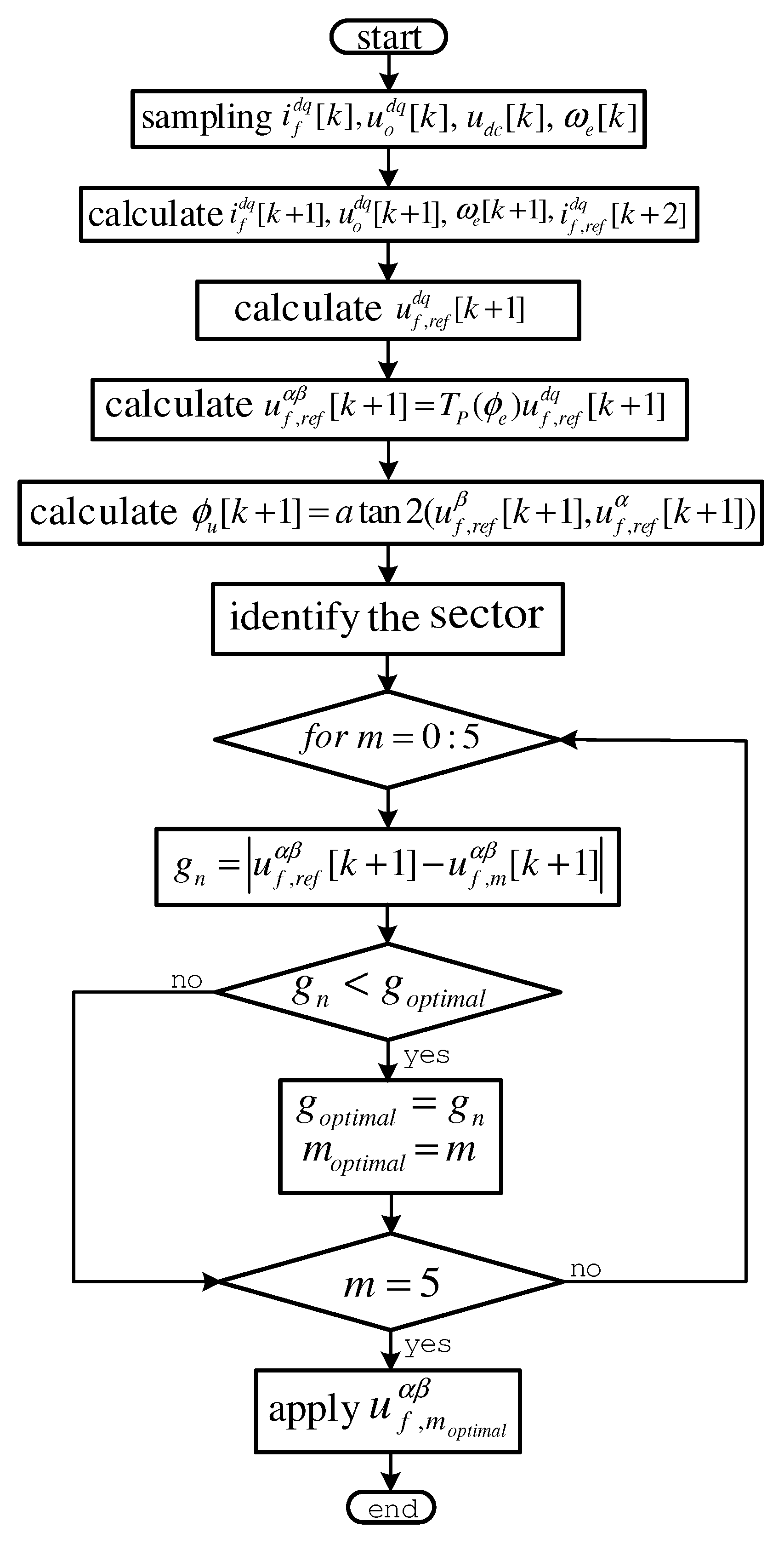
Subsequently, by using the Park transformation, this reference voltage vector is transformed from the rotating reference frame to the stationary reference frame . Consequently, the sector where this reference voltage vector is located can be easily identified by its angle:
Then, one sector from the twelve sectors illustrated in Figure 2b is selected. For example, if the angle , the reference voltage vector is located in sector 1 and the candidates voltage vectors are , , , 111, , and 112. Accordingly, the new cost function is defined as
This cost function is evaluated six times to get the optimal voltage vector. The block-diagram of the suggested DMPC is depicted in Figure 4 and its flow-chart is shown in Figure 5.
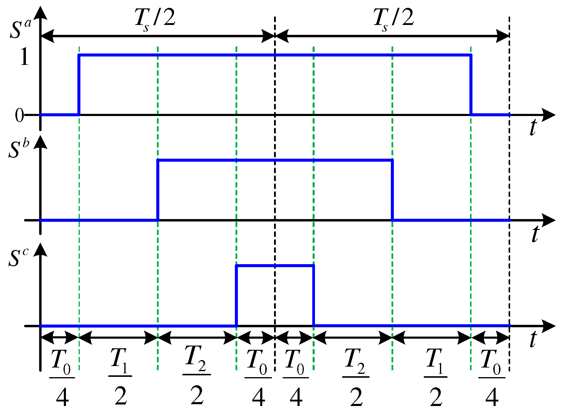
After selection of the optimal voltage vector to apply for the power converter in the next sampling instant, the switching pulses are generated using the symmetrical pulsation method with both zero voltage vectors (i.e., 000 and 111). For example, if the optimal voltage vector is , the switching sequence using symmetrical pulsation method is illustrated in Figure 6. The durations of the zero VV, first VV, and second VV are equal, are . This method produces less harmonic distortion in comparison with other techniques, such as flattop [38]. Furthermore, the switching frequency of the proposed DMPC is constant by using this technique.
Disturbance Observer
The values and are obtained usually from data-sheets of the resistance and inductance, or they can be measured under certain conditions. However, the values and are unidentified. Furthermore, they vary because of changes in temperature and frequency or due to aging. Accordingly, it is complicated to obtain the exact values of and . Furthermore, the values , of the un-modeled dynamics are also hard to measure.
Therefore, a very simple disturbance observer is proposed in this work to compensate the mismatches due to variations of the parameters and any un-modeled dynamics. The proposed disturbance observer is based on adding a discrete-time integral term to the reference voltage calculation. Hence, can be estimated as follows.
6. Simulation Results
For the validation of the proposed DMPC with enhanced steady-state/dynamic responses, a 20 power converter tied to the grid was implemented in Matlab/Simulink. Table 1 lists the parameters of the simulated system. Moreover, the classical FCS-MPC and VOC techniques have been also implemented in Matlab/Simulink. The performances of the three control schemes, i.e., proposed DMPC, traditional DMPC, and VOC, were compared at different operation conditions. The sampling/switching frequency of the proposed DMPC and VOC was selected to be 10 , and the sampling frequency of the traditional DMPC was set to 25 . For fair comparison, the magnitude optimum (MO) technique was utilized to tune the PI regulators [40]. The MO method gives a fast tracking response with minimum overshooting. Furthermore, it offers very good disturbance-rejection ability.
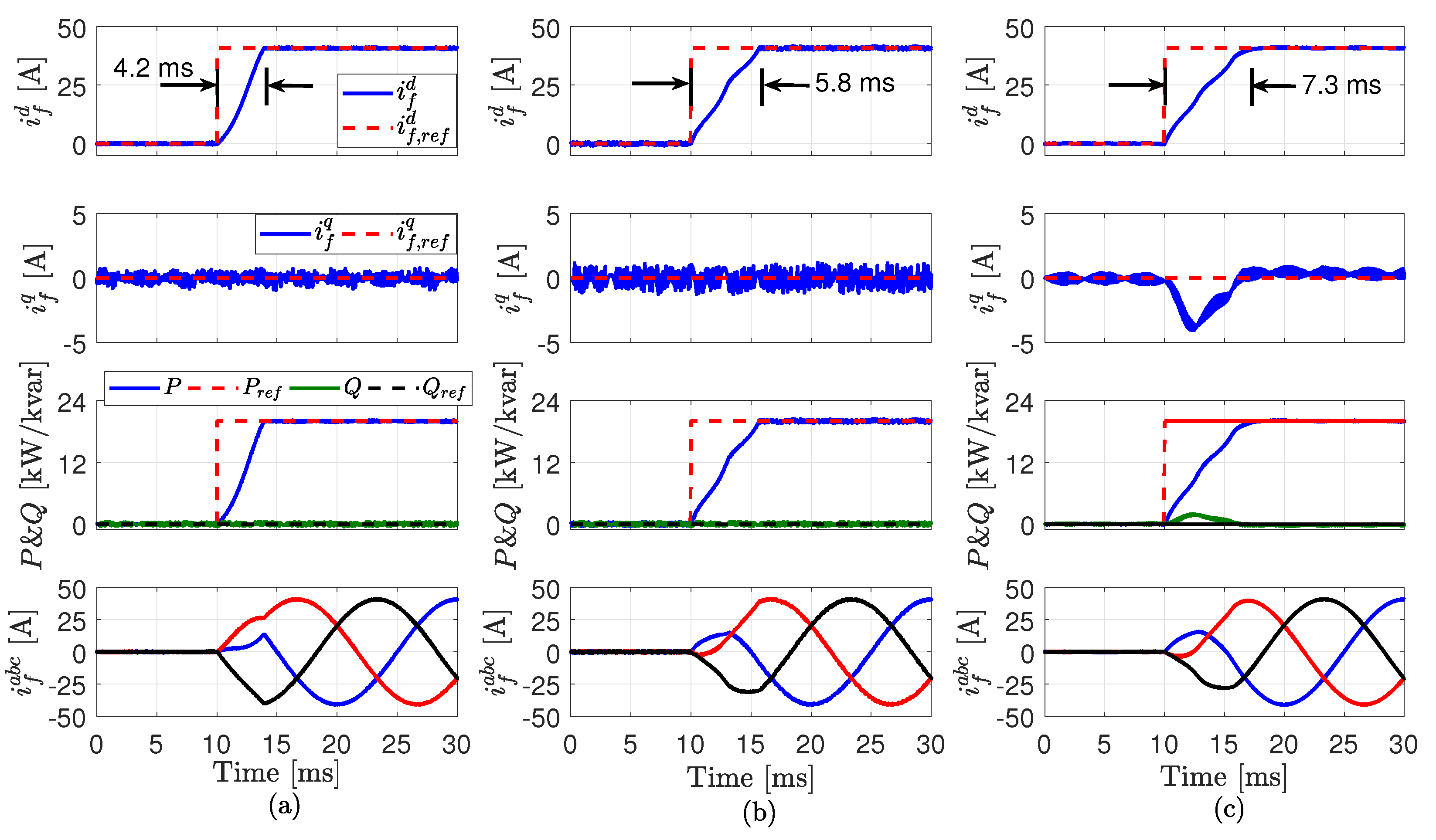
Figure 7 illustrates the dynamic responses of the different control techniques under step change in the reference active power from 0 to 20 (rated power) at the time instant . This operation condition was carried out at the nominal parameters of the filter; i.e., and . Based on Figure 7, it can be seen that the suggested DMPC gives the fastest dynamic performance in comparison with the other two control techniques. The settling times of the proposed DMPC, traditional DMPC, and VOC were , , and , respectively. Furthermore, it can be observed that by using the proposed and traditional DMPC, the q-axis current control is not effected by the step change in the d-axis current, while by using VOC the q-axis current is deviated from its reference value, see Figure 7. The execution times of the presented DMPC, traditional DMPC, and VOC were , , and , respectively. Accordingly, the computational load of the suggested DMPC is smaller than that of the classical DMPC.
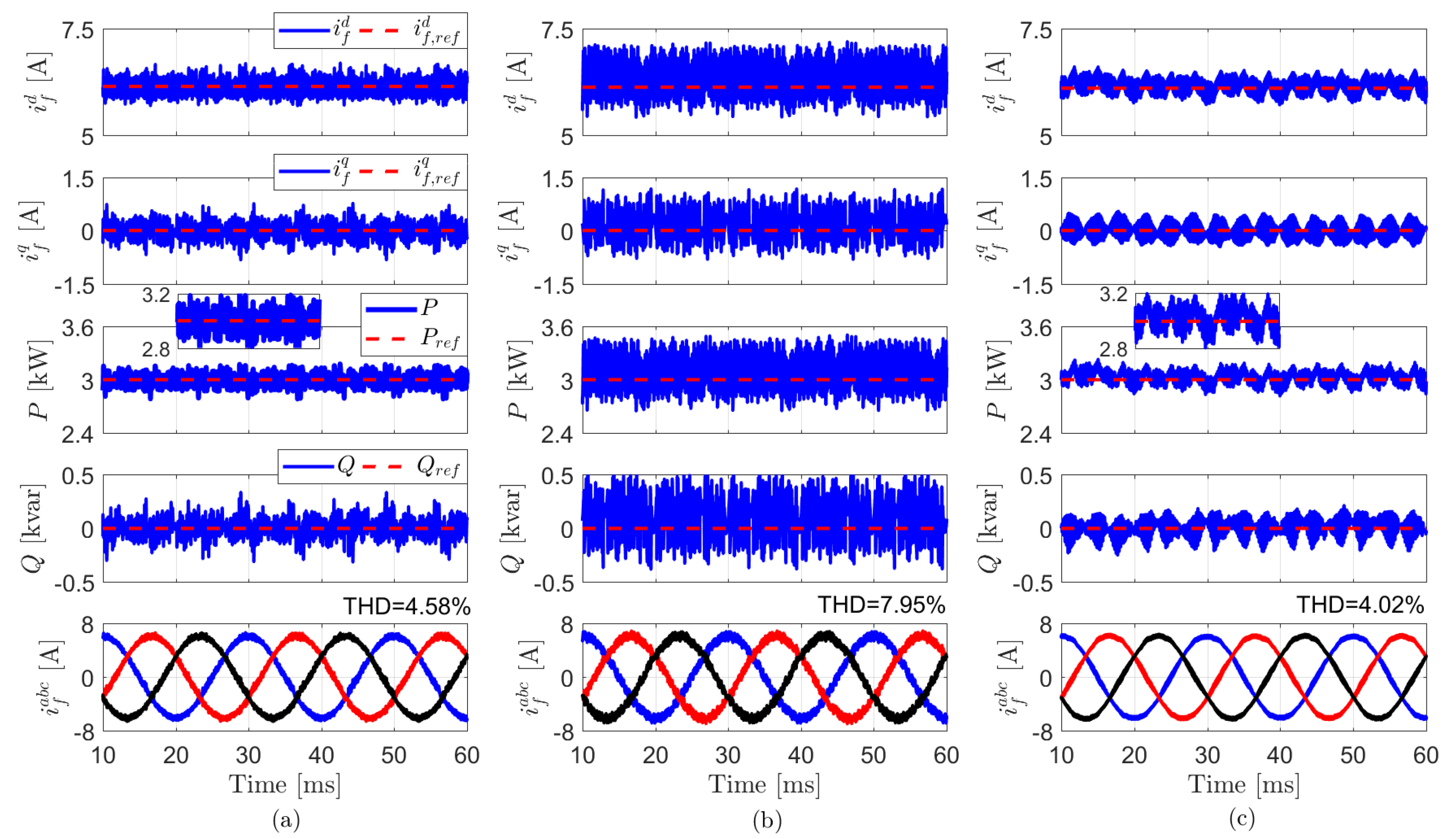
The steady-state responses of the different control schemes is illustrated in Figure 8. The reference active power is set to 3 and the nominal parameters of the filter are used; i.e., and . It can be observed that the ripples in the waveforms of the current/power using the suggested DMPC are remarkably smaller than the ripples using the conventional DMPC and almost similar to the ripples of the VOC. For better observation, the waveforms of the active power P for the proposed DMPC and VOC are zoomed from to and illustrated in Figure 8. Furthermore, the error in the steady-state of the proposed DMPC and VOC is zero, while a non-zero error in the steady-state can be seen by using the traditional DMPC, thanks to the discrete-time integral term. The total harmonic distortions (THDs) of the output current using the proposed DMPC, traditional DMPC, and VOC were , , and , respectively. Hence, the THD of the proposed DMPC is almost the same as that of the VOC.
Finally, the robustness of the three control schemes was tested under variations of the filter inductance. At the time instant , the filter inductance was reduced to pu (i.e., ) and then was increased to pu (i.e., ) at . The reference active power was set to 15 . Based on Figure 9, it can be seen that the proposed DMPC and VOC techniques are robust to variations of the filter inductance . This is due to the inclusion of discrete-time integral term in the design of the proposed DMPC. For VOC, PI controllers are used, and accordingly, the integral parts of the PI regulators enhance the robustness against variations of the model parameters. The traditional DMPC is highly sensitive to variations of the filter inductance , where high ripples and deviation of the actual current from its reference value are observed at decreasing and increasing the filter inductance .
7. Conclusions
In this paper, an efficient and robust direct model predictive control (DMPC) scheme with enhanced dynamic and steady-state performances for power converters tied to the electric utility is proposed. In the proposed DMPC, real and virtual voltage vectors (VVs) are used to minimize the ripples in the waveforms of the output current and power. Furthermore, for avoiding the high computational burden, the reference VV is straightway obtained using the deadbeat principle. Subsequently, a discrete-time integral term is added to the reference voltage vector calculation to improve the robustness of the suggested DMPC technique to uncertainties/mismatches in the parameters of the system model. Finally, the cost function selected the best switching state, which will be applied for the power converter in the following sample. The presented technique was verified by simulation results and its response was compared with the performances of both (1) the classical DMPC and (2) the famous voltage-oriented control (VOC). The results have illustrated that: (1) the dynamic response of the suggested DMPC technique is the best in comparison with both the traditional DMPC and VOC methods, (2) the computational load of the suggested DMPC is smaller than that of the traditional FCS-MPC and slightly higher than the calculation burden of VOC, (3) the ripples in the current/power using the proposed DMPC are remarkably smaller than those of the conventional DMPC and almost similar to the ripples of the VOC, and (4) the proposed DMPC and VOC are robust to uncertainties/mismatches in the parameters of the system model, while the traditional DMPC is sensitive. Accordingly, as a general conclusion, it can be affirmed that the proposed technique presented in this paper appears as a competitive alternative in comparison to the classical VOC.
Author Contributions
M.A. conceived, designed, and implemented the proposed control strategy, and wrote the manuscript. J.R. and R.K. reviewed the manuscript and were responsible for the guidance and a number of key suggestions. All authors have read and agreed to the published version of the manuscript.
Funding
This research was partially funded by ANID through projects FB0008, ACT192013 and 1170167. The APC was funded by the German Research Foundation (DFG) and the Technical University of Munich (TUM) in the framework of the Open Access Publishing Program.
Acknowledgments
This work was supported by the German Research Foundation (DFG) and the Technical University of Munich (TUM) in the framework of the Open Access Publishing Program. J. Rodriguez acknowledges the support of ANID through projects FB0008, ACT192013 and 1170167.
Conflicts of Interest
The authors declare no conflict of interest.
References
- Liserre, M.; Cardenas, R.; Molinas, M.; Rodriguez, J. Overview of Multi-MW Wind Turbines and Wind Parks. IEEE Trans. Ind. Electron. 2011, 58, 1081–1095. [Google Scholar] [CrossRef]
- Abdelrahem, M.; Hackl, C.; Kennel, R. Finite Position Set-Phase Locked Loop for Sensorless Control of Direct-Driven Permanent-Magnet Synchronous Generators. IEEE Trans. Power Electron. 2018, 33, 3097–3105. [Google Scholar] [CrossRef]
- Koutroulis, E.; Blaabjerg, F. Overview of Maximum Power Point Tracking Techniques for Photovoltaic Energy Production System. Electr. Power Compon. Syst. 2015, 43, 1329–1351. [Google Scholar] [CrossRef]
- Carrasco, J.M.; Franquelo, L.G.; Bialasiewicz, J.T.; Galván, E.; PortilloGuisado, R.C.; Prats, M.M.; Moreno-Alfonso, N. Power-electronic systems for the grid integration of renewable energy sources: A survey. IEEE Trans. Ind. Electron. 2006, 53, 1002–1016. [Google Scholar] [CrossRef]
- Blaabjerg, F.; Teodorescu, R.; Liserre, M.; Timbus, A.V. Overview of Control and Grid Synchronization for Distributed Power Generation Systems. IEEE Trans. Ind. Electron. 2006, 53, 1398–1409. [Google Scholar] [CrossRef] [Green Version]
- Malinowski, M.; Kazmierkowski, M.P.; Trzynadlowski, A. Review and Comparative study of Control Techniques for Three-Phase PWM Rectifiers. Math. Comput. Simul. 2003, 63, 349–361. [Google Scholar] [CrossRef]
- Kadri, R.; Gaubert, J.P.; Champenois, G. An Improved Maximum Power Point Tracking for Photovoltaic Grid-Connected Inverter Based on Voltage-Oriented Control. IEEE Trans. Ind. Electron. 2001, 58, 66–74. [Google Scholar] [CrossRef]
- Jeong, H.G.; Lee, K.B. A control scheme to fulfill the grid-code under various fault conditions in the grid-connected wind turbines. Electr. Eng. J. 2014, 96, 199–210. [Google Scholar] [CrossRef]
- Islam, K.A.; Abdelrahem, M.; Kennel, R. Efficient Finite Control Set-Model Predictive control for Grid-Connected Photovoltaic Inverters. In Proceedings of the 2016 International Symposium on Industrial Electronics (INDEL 2016), Banja Luka, Bosnia and Herzegovina, 3–5 November 2016; pp. 1–6. [Google Scholar]
- Abdelrahem, M.; Kennel, R. Fault-Ride through Strategy for Permanent-Magnet Synchronous Generators in Variable-Speed Wind Turbines. Energies 2016, 9, 1066. [Google Scholar] [CrossRef]
- Abdelrahem, M.; Hackl, C.; Kennel, R. Simplified Model Predictive Current Control without Mechanical Sensors for Variable-Speed Wind Energy Conversion Systems. Electr. Eng. 2017, 99, 367–377. [Google Scholar] [CrossRef]
- Abdelrahem, M.; Hackl, C.; Kennel, R. Model Predictive Control of Permanent Magnet Synchronous Generators in Variable-Speed Wind Turbine Systems. In Proceedings of the Power and Energy Student Summit (PESS 2016), Aachen, Germany, 19–20 January 2016. [Google Scholar]
- Abdelrahem, M.; Kennel, R. Efficient Direct Model Predictive Control for Doubly-Fed Induction Generators. Electr. Power Compon. Syst. 2017, 45, 574–587. [Google Scholar] [CrossRef]
- Rodriguez, J.; Cortes, P. Predictive Control of Power Converters and Electrical Drives, 1st ed.; Wiley-IEEE Press: New York, NY, USA, 2012. [Google Scholar]
- Abdelrahem, M.; Hackl, C.; Zhang, Z.; Kennel, R. Robust Predictive Control for Direct-Driven Surface-Mounted Permanent-Magnet Synchronous Generators Without Mechanical Sensors. IEEE Trans. Energy Convers. 2018, 33, 179–189. [Google Scholar] [CrossRef]
- Mohamed, Y.; El-Saadany, E. Robust High Bandwidth Discrete-Time Predictive Current Control with Predictive Internal Model-A Unified Approach for Voltage-Source PWM Converters. IEEE Trans. Power Electr. 2008, 23, 126–136. [Google Scholar] [CrossRef]
- Cortes, P.; Kazmierkowski, M.; Kennel, R.; Quevedo, D.; Rodriguez, J. Predictive control in power electronics and drives. IEEE Trans. Ind. Electron. 2008, 55, 4312–4324. [Google Scholar] [CrossRef]
- Hackl, C. MPC with analytical solution and integral error feedback for LTI MIMO systems and its application to current control of grid-connected power converters with LCL-filter. In Proceedings of the 3rd Symposium on Predictive Control of Electrical Drives and Power Electronics (PRECEDE 2015), Valparaiso, Chile, 5–6 October 2015; pp. 61–66. [Google Scholar]
- Sangsefidi, Y.; Ziaeinejad, S.; Mehrizi-Sani, A. Low Switching Frequency-Based Predictive Control of a Grid-Connected Voltage-Sourced Converter. IEEE Trans. Energy Convers. 2017, 32, 686–697. [Google Scholar] [CrossRef]
- Antoniewicz, P.; Kazmierkowski, M.P. Virtual-Flux-Based Predictive Direct Power Control of AC/DC Converters with Online Inductance Estimation. IEEE Trans. Ind. Electr. 2008, 55, 4381–4390. [Google Scholar] [CrossRef]
- Judewicz, M.; Fischer, J.; Herran, M.; Gonzalez, S.; Carrica, D. A Robust Model Predictive Control For Grid-Connected Voltage-Source Inverters. IEEE Latin Am. Trans. 2013, 11, 27–33. [Google Scholar] [CrossRef]
- Zhang, Y.; Xu, D.; Liu, J.; Gao, S.; Xu, A. Performance Improvement of Model-Predictive Current Control of Permanent Magnet Synchronous Motor Drives. IEEE Trans. Ind. Appl. 2017, 53, 3683–3695. [Google Scholar] [CrossRef]
- Abdelrahem, M.; Hamadto, F.; Garikapati, A.; Kennel, R.; Rodriguez, J. Multiple-Vector Direct Model Predictive Control for Grid-Connected Power Converters with Reduced Calculation Burden. In Proceedings of the IEEE International Symposium on Predictive Control of Electrical Drives and Power Electronics (PRECEDE), Quanzhou, China, 31 May–2 June 2019; pp. 1–6. [Google Scholar]
- Tarisciotti, L.; Zanchetta, P.; Watson, A.; Clare, J.C.; Degano, M.; Bifaretti, S. Modulated Model Predictive Control for a Three-Phase Active Rectifier. IEEE Trans. Ind. Appl. 2015, 51, 1610–1620. [Google Scholar] [CrossRef]
- Zhang, Y.; Bai, Y.; Yang, H. A Universal Multiple-Vector-Based Model Predictive Control of Induction Motor Drives. IEEE Trans. Power Electr. 2018, 33, 6957–6969. [Google Scholar] [CrossRef]
- Zhang, Y.; Xu, D.; Huang, L. Generalized Multiple-Vector-Based Model Predictive Control for PMSM Drives. IEEE Trans. Ind. Electron. 2018, 65, 9356–9366. [Google Scholar] [CrossRef]
- Kang, S.; Soh, J.; Kim, R. Symmetrical Three-Vector-Based Model Predictive Control With Deadbeat Solution for IPMSM in Rotating Reference Frame. IEEE Trans. Ind. Electron. 2020, 67, 159–168. [Google Scholar] [CrossRef]
- Kwak, S.; Moon, U.; Park, J. Predictive-Control-Based Direct Power Control With an Adaptive Parameter Identification Technique for Improved AFE Performance. IEEE Trans. Power Electron. 2014, 29, 6178–6187. [Google Scholar] [CrossRef]
- Abdelrahem, M.; Hackl, C.; Kennel, R. Finite set model predictive control with on-line parameter estimation for active frond-end converters. Electri. Eng. 2018, 100, 1497–1507. [Google Scholar] [CrossRef]
- Farhan, A.; Abdelrahem, M.; Saleh, A.; Shaltout, A.; Kennel, R. Simplified Sensorless Current Predictive Control of Synchronous Reluctance Motor Using Online Parameter Estimation. Energies 2020, 13, 492. [Google Scholar] [CrossRef] [Green Version]
- Hammoud, I.; Morsy, K.; Abdelrahem, M.; Kennel, R. Efficient model predictive power control with online inductance estimation for photovoltaic inverters. Electr. Eng. 2019. [Google Scholar] [CrossRef]
- Lin, C.; Liu, T.; Yu, J.; Fu, L.; Hsiao, C. Model free predictive current control for interior permanent-magnet synchronous motor drives based on current difference detection technique. IEEE Trans. Ind. Electron. 2014, 61, 667–681. [Google Scholar] [CrossRef]
- Lin, C.; Yu, J.; Lai, Y.; Yu, H. Improved model-free predictive current control for synchronous reluctance motor drives. IEEE Trans. Ind. Electron. 2016, 63, 3942–3953. [Google Scholar] [CrossRef]
- Zhang, X.; Zhang, L. Model Predictive Current Control for PMSM Drives with Parameter Robustness Improvement. IEEE Trans. Power Electron. 2019, 34, 1645–1657. [Google Scholar] [CrossRef]
- Yan, L.; Dou, M.; Zhang, H.t.; Hua, Z.; Yang, J. Robustness Improvement of FCS-MPTC for Induction Machine Drives Using Disturbance Feedforward Compensation Technique. IEEE Trans. Power Electron. 2019, 34, 2874–2886. [Google Scholar] [CrossRef]
- Chen, W.H.; Yang, J.; Guo, L.; Li, S. Disturbance-Observer-Based Control and Related Methods–An Overview. IEEE Trans. Ind. Electron. 2016, 63, 1083–1095. [Google Scholar] [CrossRef] [Green Version]
- Jamma, M.; Barara, M.; Akherraz, M. Voltage Oriented Control of Three-Phase PWM Rectifier Using Space Vector Modulation and Input Output Feedback Linearization Theory. In Proceedings of the International Conference of Electronics, Computers and Artificial Intelligence, Ploiesti, Romania, 30 June–2 July 2016. [Google Scholar]
- Valentine, R. Motor Control Electronics Handbook; McGraw-Hill: New York, NY, USA, 1998. [Google Scholar]
- Abdelrahem, M.; Hackl, C.; Kennel, R.; Rodriguez, J. Efficient Direct-Model Predictive Control with Discrete-Time Integral Action for PMSGs. IEEE Trans. Energy Convers. 2019, 34, 1063–1072. [Google Scholar] [CrossRef]
- Aström, K.; Hägglund, T. PID Controller: Theory, Design, and Tuning, 2nd ed.; The Instrumentation, Systems, and Automation Society (ISA): Pittsburgh, PA, USA, 1995. [Google Scholar]
Figure 1.
Schematic-diagram of the VOC technique for grid-tied power converters.

Figure 2.
For a 2-level power converter: (a) real switching VVs, and (b) real and virtual switching VVs.
Figure 2.
For a 2-level power converter: (a) real switching VVs, and (b) real and virtual switching VVs.

Figure 3.
Block-diagram of the traditional DMPC for power converters tied to the grid.

Figure 4.
Block-diagram of the proposed DMPC for power converters tied to the electric utility.

Figure 5.
Flow-chart of the presented DMPC for power converters tied to the grid.

Figure 6.
Switching pulses of the power converter in one sampling period.

Figure 7.
Dynamic performance of the different control techniques: (a) proposed DMPC, (b) traditional DMPC, and (c) VOC.
Figure 7.
Dynamic performance of the different control techniques: (a) proposed DMPC, (b) traditional DMPC, and (c) VOC.

Figure 8.
Steady-state performance of the different control techniques: (a) proposed DMPC, (b) traditional DMPC, and (c) VOC.
Figure 8.
Steady-state performance of the different control techniques: (a) proposed DMPC, (b) traditional DMPC, and (c) VOC.

Figure 9.
Performances of the different control techniques at variations of the filter inductance : (a) proposed DMPC, (b) traditional DMPC, and (c) VOC.
Figure 9.
Performances of the different control techniques at variations of the filter inductance : (a) proposed DMPC, (b) traditional DMPC, and (c) VOC.


Table 1.
List of parameters of the power converter under study.
| Name | Nomenclature | Value |
|---|---|---|
| Rated power | 20 | |
| DC-link voltage | 700 | |
| AC line-line voltage | 400 | |
| Grid normal frequency | 50 | |
| Filter resistance | ||
| Filter inductance | 12 |
© 2020 by the authors. Licensee MDPI, Basel, Switzerland. This article is an open access article distributed under the terms and conditions of the Creative Commons Attribution (CC BY) license (http://creativecommons.org/licenses/by/4.0/).
Share and Cite
MDPI and ACS Style
Abdelrahem, M.; Rodríguez, J.; Kennel, R. Improved Direct Model Predictive Control for Grid-Connected Power Converters. Energies 2020, 13, 2597. https://doi.org/10.3390/en13102597
AMA Style
Abdelrahem M, Rodríguez J, Kennel R. Improved Direct Model Predictive Control for Grid-Connected Power Converters. Energies. 2020; 13(10):2597. https://doi.org/10.3390/en13102597
Chicago/Turabian StyleAbdelrahem, Mohamed, José Rodríguez, and Ralph Kennel. 2020. "Improved Direct Model Predictive Control for Grid-Connected Power Converters" Energies 13, no. 10: 2597. https://doi.org/10.3390/en13102597
Note that from the first issue of 2016, this journal uses article numbers instead of page numbers. See further details here.